EP2284024A1 - Tensioning device for snow chains - Google Patents
Tensioning device for snow chains Download PDFInfo
- Publication number
- EP2284024A1 EP2284024A1 EP10175321A EP10175321A EP2284024A1 EP 2284024 A1 EP2284024 A1 EP 2284024A1 EP 10175321 A EP10175321 A EP 10175321A EP 10175321 A EP10175321 A EP 10175321A EP 2284024 A1 EP2284024 A1 EP 2284024A1
- Authority
- EP
- European Patent Office
- Prior art keywords
- ratchet
- tensioning device
- housing
- ratchet spool
- teeth
- Prior art date
- Legal status (The legal status is an assumption and is not a legal conclusion. Google has not performed a legal analysis and makes no representation as to the accuracy of the status listed.)
- Withdrawn
Links
Images


Classifications
-
- B—PERFORMING OPERATIONS; TRANSPORTING
- B60—VEHICLES IN GENERAL
- B60C—VEHICLE TYRES; TYRE INFLATION; TYRE CHANGING; CONNECTING VALVES TO INFLATABLE ELASTIC BODIES IN GENERAL; DEVICES OR ARRANGEMENTS RELATED TO TYRES
- B60C27/00—Non-skid devices temporarily attachable to resilient tyres or resiliently-tyred wheels
- B60C27/06—Non-skid devices temporarily attachable to resilient tyres or resiliently-tyred wheels extending over the complete circumference of the tread, e.g. made of chains or cables
- B60C27/10—Non-skid devices temporarily attachable to resilient tyres or resiliently-tyred wheels extending over the complete circumference of the tread, e.g. made of chains or cables having tensioning means
- B60C27/12—Non-skid devices temporarily attachable to resilient tyres or resiliently-tyred wheels extending over the complete circumference of the tread, e.g. made of chains or cables having tensioning means resilient pretension
-
- B—PERFORMING OPERATIONS; TRANSPORTING
- B60—VEHICLES IN GENERAL
- B60C—VEHICLE TYRES; TYRE INFLATION; TYRE CHANGING; CONNECTING VALVES TO INFLATABLE ELASTIC BODIES IN GENERAL; DEVICES OR ARRANGEMENTS RELATED TO TYRES
- B60C27/00—Non-skid devices temporarily attachable to resilient tyres or resiliently-tyred wheels
- B60C27/06—Non-skid devices temporarily attachable to resilient tyres or resiliently-tyred wheels extending over the complete circumference of the tread, e.g. made of chains or cables
- B60C27/10—Non-skid devices temporarily attachable to resilient tyres or resiliently-tyred wheels extending over the complete circumference of the tread, e.g. made of chains or cables having tensioning means
Definitions
- the present invention relates generally to snow chains, particularly, snow chains that self-tighten to ensure proper fit. More particularly, the present invention relates to self-tightening snow chains having a tensioning device including a winding device and a tensioning cord, the snow chains having a tensioned mode when secured for use on a wheel of a land vehicle and a separate extended mode, wherein the tensioning cord, interconnected with the winding device is released to extend away from the winding device to permit the snow chain to be easily engaged with the wheel of the land vehicle prior to securing the snow chain to the wheel. In alternate embodiments, the present invention relates to self-tightening snow chains that self-tighten when a plurality of cords are tensioned by a single winding device.
- the present invention relates to a tensioning device for a snow chain that places a spring bias upon a tensioning cord or a plurality of tensioning cords and/or is resistant to infiltration of dirt, debris and moisture. Methods of providing and using these inventions are also disclosed.
- Self-tightening snow chains have been used to provide vehicles with improved traction when driving on irregular surfaces where poorer traction is anticipated (i.e. ice or snow covered surfaces, off-road or backcountry terrains). Numerous states require the use of snow chain under certain weather conditions to mitigate potential hazards. Most models of snow chains require retightening after initial chain installation, where all of the wheel chains need to be retightened after the vehicle has been slowly driven forward or backward. It is essential that snow chains fit properly to obtain proper performance and increase durability. Having to retighten the cables is burdensome for the user and has costly consequences if forgotten or neglected.
- the Franklin patent discloses a clamping lock for a traction device.
- the lock has a single clamping rope connected to a winding device within a housing.
- the winding device is pre-tensioned in the wind-up direction. Toothing is provided laterally around the winding device.
- actuating lever attached to the housing that has three positions: a first catch position, which allows the clamping rope to move in or out of the housing; a second wind-up position, which unlocks the rope so it may move into the housing, thereby tightening the clamping rope; and a third locked position wherein the clamping rope is locked in its current position.
- the lever controls a pawl. Whether or not the clamping rope may be pulled in or out of the housing depends on whether the pawl is engaged with the teeth on the winding device.
- Self-tightening snow chains having tensioning devices of this kind are difficult to secure to a wheel of a vehicle with two hands.
- a user may need to let go of the cord in order to better grip the tensioning device or grab the corresponding hook on the snow chain.
- the user In order to prevent the cord from being pulled back into the housing, the user must lock the cord in both directions to keep the cord in the extended position. Then, the cord would need to be unlocked to extend further, again requiring releasing either the cord or the corresponding hook.
- self-tightening snow chain tensioning devices that can only tighten one cord are less cost effective because numerous self-tightening tensioning devices are required on each snow chain to tighten each cord.
- self-tightening snow chain tensioning devices of this kind are made by simply screwing two flat-edged housing pieces together. Dirt, debris and moisture may easily penetrate this type of joint and cause damage to the mechanisms inside the housing. Additionally, the use of actuating levers creates an easy path for dirt, debris and moisture to enter and damage the device.
- the tensioning cord is generally equipped with crimped on or cast on ends and that one of these ends is then passed through a grommet and that the grommet and the cord are then incorporated into the tensioning device during assembly. In order to accept the crimped or cast on end, the opening in the grommet is required to be quite a bit larger than the diameter of the cord and the difference in size provides another area where an easy path is provided for dirt, debris and moisture to enter and damage the device.
- the present invention provides a self-tensioning snow chain for attachment to a wheel of a vehicle, the self-tensioning snow chain includes a snow chain; and a tensioning device.
- the tensioning device includes (1) a housing having a top including a set of housing teeth, a bottom and at least one aperture defined by the top and the bottom when joined together; (2) a lever interconnected to the housing; (3) a cord; (4) a ratchet spool having a set of ratchet teeth on an upper surface, the ratchet teeth constructed and arranged to mate with the housing teeth, an under surface and a channel between the upper surface and the under surface in which sufficient space is provided to receive the cord, wherein the cord is interconnected with the ratchet spool; (5) a tension spring interconnected with the ratchet spool and constructed and arranged to place a bias on the ratchet spool toward a wind-up direction; and (6) a wave spring positioned between a top surface of the bottom of the housing and the under
- the present invention achieves these and other objectives by providing a self-tightening snow chain having two modes of operation.
- First is an extended or extending mode that allows the user to extend the cord from the housing and release their grip on the cord without having the cord wind-up into the housing.
- the ability to only allow movement in a wind-out direction is created when the ratchet spool is in down position, where the spool, although biased in a wind-up direction, is blocked from turning in a wind-up direction.
- the user raises the actuating lever until it is perpendicular to the housing. This action forces a cam-lever to push the ratchet spool down.
- the ratchet teeth are disengaged from the housing teeth thereby allowing movement of the ratchet spool in either direction.
- movement in the wind-up direction is prevented by catches on the under surface of a ratchet spool that are pushed into a zone of a stop or stopper where they will be blocked by the stopper, thereby stopping the ratchet spool from turning in a wind-up direction more than a full turn, a half turn or preferably a quarter turn.
- the cord simply needs to be pulled further outward.
- Second is a self-tightening mode wherein the cord may only move in the wind-up direction.
- This mode is for when the cord is engaged and in use and the user wants to maintain constant tension on the snow chain without the possibility of the cord extending out.
- the user lowers the actuating lever until it snaps back into a position adjacent to the housing.
- the actuating lever is down, the ratchet spool is up. Therefore, the housing teeth and the ratchet teeth are engaged to only allow movement in the wind-up direction.
- the catches cannot be blocked by the stopper, which would otherwise prevent more than a small movement of the ratchet spool in the wind-up direction.
- the ratchet and housing teeth may be overcut or undercut.
- the respective teeth will be undercut at an angle ranging from about 3 to about 30 degrees, preferably about 5 to about 25 degrees more than the 90 degree angle to a horizontal plane b perpendicular to a vertical axis c of the ratchet spool and the housing.
- the respective teeth will be undercut about 20 degrees more than the 90 degree angle to a horizontal plane b perpendicular to a vertical axis c of the ratchet spool and the housing.
- a plurality of cords may extend from different apertures or openings of the housing.
- a tensioning device may be difficult to optimize because of the limited room on the ratchet spool, unequal forces that could be placed on each cord when in use and also the potential need for a tension spring that can generate greater winding force on the spool that may be needed to wind a greater number of cords.
- a lip-groove configuration may be utilized to aid in sealing the housing from dirt, debris and moisture.
- a lip may trace along the opening of the housing top and a groove may trace along the opening of the housing bottom. When the two housing components are joined together, the lip and groove will mate to form a more secure seal than if two flat surfaces are pressed together.
- the lip may trace along the opening of the housing bottom and the groove may trace along the opening of the housing top.
- a grommet having an opening only slightly larger than the diameter of the cord may be utilized. If the grommet is secured around the cord prior to securing knobs at both ends of the cord, the grommet opening can be smaller than the diameter of the knobs, thereby reducing the size of the passageway in the grommet where dirt, debris and moisture can breach the housing.
- FIGURE 1 is a perspective view of one embodiment of a self-tightening snow chain of the present invention having a tensioning device, wherein the self-tightening snow chain is in use attached to a wheel (partially shown);
- FIGURE 2 is a perspective view of one embodiment a housing of a tensioning device of the present invention showing the exterior of the device shown in Figure 1 ;
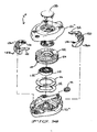
- FIGURE 3 is an exploded perspective view of the one embodiment of a tensioning device of the present invention showing the internal and external components shown in Figure 1 ;
- FIGURE 4 is an exploded partial schematic view of certain components of the tensioning device of one embodiment of the tensioning device of the present invention showing the location of the ratchet spool, the compression spring and the stopper shown in Figures 1 and 3 ;
- FIGURE 5 is a partial perspective view of a stopper and compression spring fitted in a housing bottom, of the tensioning device of the present invention shown in Figure 4 ;
- FIGURE 6 is a partial perspective view of a portion of the housing of the tensioning device of the present invention showing a housing lip-groove configuration joint shown in Figures 1 and 3 ;
- FIGURE 7A is a perspective view of a tensioning cord sub-unit of the tensioning device of the present invention shown in Figures 1 and 3 ;
- FIGURE 7B is a perspective view of the tensioning cord sub-unit shown in Figure 7A before it is completely assembled;
- FIGURE 8A is a partial, schematic view of the tensioning device of Figure 1 showing the internal components when the lever is in a down position and the ratchet spool is in an up position within the housing, which is shown in phantom, but without showing the wave spring to permit clarity;
- FIGURE 8B is a partial, schematic view of the tensioning device shown in Figure 1 , similar to that shown in Figure 8A , but showing the internal components when the lever is in an up position and the ratchet spool is in a down position;
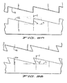
- FIGURE 9A is an enlarged, partial, schematic view of a portion of tensioning device shown in area 9a-9a of Figure 8B illustrating enlarged ratchet teeth and housing teeth cut at an angle of about 90 degrees to a horizontal plane perpendicular to a vertical axis of the ratchet spool and the housing;
- FIGURE 9B is an enlarged, partial, schematic view similar to that shown in Figure 9A but illustrating a preferred embodiment, wherein the ratchet and housing teeth are undercut about 20 degrees more than a 90 degree angle to a horizontal plane b perpendicular to a vertical axis c of the ratchet spool and the housing;
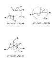
- FIGURE 10A is a diagrammatic view of one embodiment of the tensioning device of the present invention showing a preferred positioning on a wheel of two, single-cord tensioning devices similar to that shown in Figure 1 ;
- FIGURE 10B is a diagrammatic view of one embodiment of an alternate tensioning device of the present invention showing a preferred positioning of a single, dual cord tensioning device that tightens two tensioning cords with respect to a snow cable (not shown) on a wheel;
- FIGURE 10C is a diagrammatic view of one embodiment of an alternate tensioning device of the present invention showing a preferred positioning of a single, multiple cord tensioning device that tightens three tensioning cords with respect to a snow cable (not shown) on a wheel;
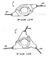
- FIGURE 11A is a plan view of a dual cord tensioning device, similar to the tensioning device shown in Figure 1 , but where two cords are tensioned in a single tensioning device;
- FIGURE 11B is a plan view of a triple cord tensioning device, similar to the tensioning device shown in Figure 1 , but where three cords are tensioned in a single tensioning device;
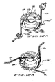
- FIGURE 12A is a perspective view of one embodiment, a ratchet spool, similar to that shown in Figure 3 , for a dual cord tensioning device of the present invention wherein two tensioning cords are wrapped around a single ratchet spool; when the cords are fully wound in;
- FIGURE 12B is a perspective view of one embodiment, a ratchet spool for a triple cord tensioning device of the present invention wherein three tensioning cords are wrapped around a single ratchet spool when the cords are fully wound in;
- FIGURE 13 is a perspective view of an alternate embodiment of a tensioning device of the present invention wherein buttons are used to change device modes;
- FIGURE 14 is an exploded view of the alternate tensioning device shown in Figure 13 ;
- FIGURE 15 is a diagrammatic view of one embodiment of the alternate tensioning device of the present invention shown in Figures 13 and 14 showing the pivot and contact points of the pawls and top button;
- FIGURE 16A is a sectional view, similar to that shown in Figure 8A , but showing the alternate tensioning device of the present invention shown in Figure 13 , showing the internal components when the top button is in the down position and the ratchet spool is in the up position (wave spring not shown for clarity); and
- FIGURE 16B is a sectional view, similar to that shown in Figure 8B , but showing the alternate tensioning device of the present invention shown in Figure 13 , showing the internal components when the top button is in the down position and the ratchet spool is in the down position (wave spring not shown for clarity).
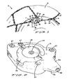
- FIG. 1 is a perspective view of a self-tightening snow chain 10 of the present invention in use on a wheel 16 (partially shown).
- the self-tightening snow chain 10 comprises of a snow chain 14 and a tensioning device 11.
- the self-tightening snow chain 10 has a housing 12 including a housing top 12a, an actuating lever 26, a grommet 32, and a cord 20 extending through grommet 32 and connected to a hook 18 with a first connection member 22.
- the hook 18 connects to the chain 14 of the self-tightening snow chain 10, to supply tension to the chain 14.
- connection point 24 there is a second connection point 24 and third connection point 30 where parts of the snow chain 14 are secured to the housing 12.
- Rivets 28 are placed through rivet receiving openings or recesses 29 to secure the housing top 12a to the housing bottom 12b, although any other fasteners such as threaded screws, bolts and nuts, adhesives, double backed tape and the like could be used.
- the housing top 12a has a recess 34 to prevent distortion during injection molding, which may additionally be used as a place for company identifiers and the like, if desired.
- FIG 2 is a perspective view of the housing 12 of the tensioning device 11 shown in Figure 1 .
- the housing top 12a can be secured to the housing bottom 12b by rivets or threaded screws (not shown) that may inserted through the holes 29.
- the housing top 12a and the housing bottom 12b define an aperture 38 for receiving the grommet 32 that provides a passageway for the tensioning cord 20.
- an actuating lever 26 including a cam 126 is pivotally connected to the housing top 12a.
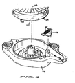
- FIG. 3 there is illustrated an exploded view of one embodiment of the tensioning device 11 of the present invention.
- a wave spring 112 sits on the inside of the housing bottom 12b.
- the wave spring 112 is positioned in a way to apply pressure to the ratchet spool 100.
- the tension spring 110 also rests inside the ratchet spool 100 and has a crimp 122 that mates with a notch 120 in the ratchet spool 100 to secure the tension spring 110 to the ratchet spool 100.
- the ratchet spool 100 has a center channel 124 running circumferentially around its exterior and is sufficiently wide and deep enough for a cord 20 to be wound within the channel 124 around the ratchet spool 100.
- the under surface 132 of the ratchet spool 100 has four catches 104. It is not essential that there be four catches 104 as two to six catches 104 will result in similar function. More than six catches 104 is possible but not recommended.
- the catches 104 prevent the ratchet spool 100 from rotating in the wind-up direction when they are blocked by the stopper 108. The catches 104 can only be blocked by the stopper 108 when the ratchet spool 100 is in the down position (when the cam 126 is in the down position/the actuating lever 26 is in the up position).
- On the top of the ratchet spool 100 are ratchet teeth 102.
- the ratchet teeth 102 can engage with the housing teeth 118 located in the housing top 12a when the actuating lever 26 is oriented in the down position.
- a cam 126 which extends from the actuating lever 26, is parallel to the plane of rotation of the ratchet spool 100. Therefore, there is no added pressure on the wave spring 112, which allows the wave spring 112 to push the ratchet spool 100 to its up position, engaging the ratchet spool 100 with the housing teeth 118.
- the cam 126 When the actuating lever 26 is in the up position/the cam 126 is in a down position and pushes the top base 114 down against the ratchet teeth 102, which are subsequently pushed down thereby disengaging the ratchet teeth 102 from the housing teeth 118.
- the top 116 has slots 117 for the cam levers 26 to rotate.
- the housing teeth 118 are molded into the housing top 12a.
- the compression spring 106 is attached to the stopper 108 and they both are placed in the housing bottom 12b such that the compression spring 106 applies force to the housing bottom 12b.
- the compression spring 106 places a bias on the stopper 108 such that the stopper 108 will block a catch 104 should the ratchet spool 100 be in the down position and rotating in the wind-up direction.
- FIG. 6 shows the lip 40 and groove 42 configuration near the aperture 38 defined by the housing 12.
- the lip 40 and groove 42 mate to form a housing joint 44 resistant to dirt, debris and moisture.
- FIGS 7A and 7B showing an assembled tensioning cord sub-unit 134.
- a cord 20 is threaded through a grommet 32 and has a first knob 128a and a second knob 128b.
- the knobs 128 may be fitted to the cord 20 by crimping, melting, casting and the like.
- the cord 20 is threaded through the grommet 32 before both of the knobs 128 are fitted to the cord 20, which permits the diameter of the grommet 32 to be smaller than the diameter of the knobs 128, so that the grommet 32 may more closely fit the cord 20, allowing the grommet to be more appropriately sized to limit the infiltration of dirt, debris and moisture into the housing 12.
- the cord 20 is attached to the first connection member 22 that is connected to a hook 18 (shown in phantom) used for securing the tensioning device 11 to parts of the snow chain 14.
- Figure 7B shows how the second knob 128b fits into a recess 46 (partially shown) formed by a first piece 22a and second piece 22b of the first connection member 22.
- the first and second pieces 22a and 22b are secured together around the second knob 128b that is tightly secured to the cord 20.
- Rivets 23 are placed through rivet receiving openings 25 to secure first and second pieces 22a and 22b together, although any other fasteners such as threaded screws, bolts and nuts, adhesives, double backed tape and the like could be used.
- Figure 8A is a sectional view showing the internal components when the actuating lever 26 is in the down position thereby allowing the ratchet spool 100 to be in the up position.
- the catches 104 are clear of the stopper 108 thereby allowing the ratchet spool 100 to freely wind-up and tighten the cord 20.
- the ratchet spool 100 may only rotate in the wind-up direction, because the ratchet teeth 102 can fully engaged with the housing teeth 118 to limit rotation if an extending or wind-out force is applied to the cord 20.
- Figure 8B is a sectional view showing the internal components when the actuating lever 26 is in the up position thereby forcing the ratchet spool 100 to be in the down position. While the ratchet spool 100 is in the down position, the ratchet teeth 102 are disengaged from the housing teeth 118. This allows the ratchet spool 100 to rotate freely in either direction.
- the catches 104 stop the ratchet spool 100 from fully rotating in the wind-up direction. As the ratchet spool 100 begins to rotate in the wind-up direction, the stopper 108 will block the next catch 104 it encounters, thereby preventing the ratchet spool 100 from further winding-up.
- the ratchet teeth 102 and the housing teeth 118 are cut at an angle "a" of about 90 degrees to a horizontal plane perpendicular to a vertical axis of the ratchet spool and the housing.
- the ratchet teeth 102 and housing teeth 118 may be overcut or undercut.
- the teeth 102, 118 may be undercut at an angle ranging from about 3 to about 30 degrees, preferably from about 10 to about 25 degrees more than a 90 degree angle to a horizontal plane b perpendicular to a vertical axis c of the ratchet spool and the housing, so that when the tensioning device 11 is in a wind-up mode and the cord is tugged outwardly, the more the ratchet teeth 118 will become engaged and resist the cord 20 being moved in the wind-out direction.
- the teeth 102, 118 are undercut at an angle a' of about 20 degrees more than a 90 degree angle to a horizontal plane b perpendicular to a vertical axis c of the ratchet spool and the housing, as illustrated in Figure 9B .
- Figure 10A is a diagrammatic view of one embodiment of the present invention showing the preferred positioning of two, single tensioning devices 11 attached to a wheel 16.
- the tensioning devices 11 are approximately 180 degrees from each other and their respective cords 20 and hooks 18 extend in opposite directions.
- Figure 10B is a diagrammatic view of one embodiment of the present invention showing the preferred positioning of a single, tensioning device 11' attached to a first cord 20 and a second cord 20a that each have their respective hooks 18.
- the tensioning device 11' is centered with the exterior of the wheel 16 to provide equal tension on the first cord 20a and the second cord 20b which extend parallel to each other.
- Figure 10C is a diagrammatic view of one embodiment of the present invention showing the preferred positioning of a single, tensioning device 11" attached to a first cord 20, a second cord 20b, and a third cord 20c that each have their respective hooks 18.
- the tensioning device 11" is centered with the exterior of the wheel 16 to provide equal tension on the first cord 20a, the second cord 20b, and the third cord 20c, which extend approximately 120 degrees from each other.
- Figure 11A shows another embodiment of the tensioning device of the present invention wherein the tensioning device 11' tensions a first cord 20a and a second cord 20b.
- Figure 11B shows another embodiment of the tensioning device 11' of the present invention, wherein the tensioning device 11" applies tension to a first cord 20a, a second cord 20b and a third cord 20c.
- Figure 12A is a perspective view of one embodiment an alternate ratchet spool 100' of the present invention showing the ratchet spool 100' configuration of having a first cord 20a and a second cord 20b that are attached to the ratchet spool 100' and wound in the channel 124.
- only two catches 104 are on the under surface 132 of the ratchet spool 100', because less space is available.
- the first cord 20a and second cord 20b have a first knob 128a fitted to their respective ends sized to fit snuggly into the ratchet spool recess 130 to prevent the first cord 20a and the second cord 20b from being pulled off of the ratchet spool 100'.
- Figure 12B shows a perspective view of an embodiment of the present invention showing a further alternate ratchet spool 100" configuration having a first cord 20a, a second cord 20b, and a third cord 20c.
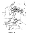
- FIG. 13-16B there is illustrated an alternate tensioning device 11"' having a housing 12"' having a housing top 12a"' and a housing bottom 12b"'.
- Located on the housing top 12a"' is a top button 138.
- a first side button 136a and a second mirroring side button 136b (not shown).
- Protruding from the housing 12"' is a grommet 32 from which a cord 20 (not shown) may pass.
- Figure 14 shows an exploded view of the tensioning device 11"' shown in Figure 13 .
- a wave spring 112 sits on the inside of the housing bottom 12b"' and is positioned in a way to apply pressure to the ratchet spool 100"'.
- a washer 156 is placed in between the wave spring 112 and the ratchet spool 100"'.
- the tension spring 110 also rests inside the ratchet spool 100"' and has a crimp 122 that may be inserted into a notch 120 (not shown) in the ratchet spool 100"' to secure the tension spring 110 to the ratchet spool 100"'.
- the ratchet spool 100"' has a channel 124 running around the outside of the ratchet spool 100"' in the center and is sufficiently wide and deep enough for a cord 20 (not shown) to be wound around it.
- On the top of the ratchet spool 100"' are ratchet teeth 102.
- the ratchet teeth 102 engage with the housing teeth 118 (not shown).
- the side buttons 136 are spring loaded with a pawl spring 154. As seen in Fig.
- the ratchet teeth 102 engage with the housing teeth 118 (not shown) located in the housing top 12a"' when the top button 138 is in the up position.
- the ratchet spool 100"' may only move in the wind-in direction to tighten the cord 20 (not shown).
- the side buttons 136 are pushed into the housing 12"'.
- the ratchet spool 100"' may move in either the wind-in or the wind-out direction. In this mode, the side buttons 136 are pushed out of the housing 12"' by the force of the spring 154.
- FIG. 15 showing the positioning of the top button 138 and the side buttons 136 when the top button 138 is in the up position.
- the side buttons 136 are pushed into the housing 12"'.
- Two button springs 154 rest against the interior of the housing top 12a"' and apply pressure to move the side buttons 136 out of the housing 12"'.
- the side buttons 136 do not move out of the housing because the pawls 152 are stopped by the top button 138.
- the pawls 152 are no longer blocked and the side buttons 136 will pop out of the housing 12"'.
- the ratchet spool 100"' may rotate freely.
- Figure 16A shows the arrangement of the side buttons 136, the top button 138, the ratchet teeth 102, and the housing teeth 118 when the top button 138 is in the up position.
- the pawls 152 engage with the ratchet teeth 102 and the ratchet spool 100"' may only move in the wind-up direction.
- the wave spring 112 is not shown.
- FIG 16B illustrating the arrangement of the top button 152, the ratchet teeth 102, and the housing teeth 118 when the top button 152 is in the down position.
- the force created by the button springs 154 (not shown) snaps the pawls 152 away from the ratchet teeth 118 so that the ratchet spool 100"' may move in the wind-in or wind-out direction.
- the user presses the side buttons 136 back into the housing 12"' to force the top button 138 back up and allow the pawls 152 to again come into contact with the ratchet teeth 118.
- the wave spring 112 is not shown.
Landscapes
- Engineering & Computer Science (AREA)
- Mechanical Engineering (AREA)
- Devices For Conveying Motion By Means Of Endless Flexible Members (AREA)
- Materials Applied To Surfaces To Minimize Adherence Of Mist Or Water (AREA)
- Vehicle Interior And Exterior Ornaments, Soundproofing, And Insulation (AREA)
- Lubricants (AREA)
- Cleaning Of Streets, Tracks, Or Beaches (AREA)
- Suspension Of Electric Lines Or Cables (AREA)
- Harvester Elements (AREA)
- Transmission Devices (AREA)
Abstract
a ratchet spool (100) having a set of ratchet teeth (102) on the upper surface, the ratchet teeth (102) constructed and arranged to mate with housing teeth (118);
a tension spring (110) and an the actuator (26) in order to engage/disengage the ratchet teeth (102) with/from the housing teeth (118);
wherein the ratchet spool (100) further includes a catch (104) on the lower surface of the ratchet spool (100) and the tensioning device (11) further includes a stopper (108), wherein the stopper (108) will block the catch (104) when the ratchet spool (100) is in the down position so that the ratchet spool (100) will not fully rotate in the wind-up direction when the ratchet spool (100) is in a down position; wherein the stopper (108) will not block the catch (104) when the ratchet spool (100) is in the up position.
Description
- The present invention relates generally to snow chains, particularly, snow chains that self-tighten to ensure proper fit. More particularly, the present invention relates to self-tightening snow chains having a tensioning device including a winding device and a tensioning cord, the snow chains having a tensioned mode when secured for use on a wheel of a land vehicle and a separate extended mode, wherein the tensioning cord, interconnected with the winding device is released to extend away from the winding device to permit the snow chain to be easily engaged with the wheel of the land vehicle prior to securing the snow chain to the wheel. In alternate embodiments, the present invention relates to self-tightening snow chains that self-tighten when a plurality of cords are tensioned by a single winding device. In further embodiments, the present invention relates to a tensioning device for a snow chain that places a spring bias upon a tensioning cord or a plurality of tensioning cords and/or is resistant to infiltration of dirt, debris and moisture. Methods of providing and using these inventions are also disclosed.
- Self-tightening snow chains have been used to provide vehicles with improved traction when driving on irregular surfaces where poorer traction is anticipated (i.e. ice or snow covered surfaces, off-road or backcountry terrains). Numerous states require the use of snow chain under certain weather conditions to mitigate potential hazards. Most models of snow chains require retightening after initial chain installation, where all of the wheel chains need to be retightened after the vehicle has been slowly driven forward or backward. It is essential that snow chains fit properly to obtain proper performance and increase durability. Having to retighten the cables is burdensome for the user and has costly consequences if forgotten or neglected.
- Because proper fit of the snow chains is so essential, self-tightening snow chains have been developed. One of these devices is disclosed in
U.S. Patent No. 6,213,421 to Franklin . The Franklin patent discloses a clamping lock for a traction device. The lock has a single clamping rope connected to a winding device within a housing. The winding device is pre-tensioned in the wind-up direction. Toothing is provided laterally around the winding device. There is an actuating lever attached to the housing that has three positions: a first catch position, which allows the clamping rope to move in or out of the housing; a second wind-up position, which unlocks the rope so it may move into the housing, thereby tightening the clamping rope; and a third locked position wherein the clamping rope is locked in its current position. The lever controls a pawl. Whether or not the clamping rope may be pulled in or out of the housing depends on whether the pawl is engaged with the teeth on the winding device. - Self-tightening snow chains having tensioning devices of this kind are difficult to secure to a wheel of a vehicle with two hands. A user may need to let go of the cord in order to better grip the tensioning device or grab the corresponding hook on the snow chain. In order to prevent the cord from being pulled back into the housing, the user must lock the cord in both directions to keep the cord in the extended position. Then, the cord would need to be unlocked to extend further, again requiring releasing either the cord or the corresponding hook. Additionally, self-tightening snow chain tensioning devices that can only tighten one cord are less cost effective because numerous self-tightening tensioning devices are required on each snow chain to tighten each cord.
- Of further concern, self-tightening snow chain tensioning devices of this kind are made by simply screwing two flat-edged housing pieces together. Dirt, debris and moisture may easily penetrate this type of joint and cause damage to the mechanisms inside the housing. Additionally, the use of actuating levers creates an easy path for dirt, debris and moisture to enter and damage the device. It is also noted that the tensioning cord is generally equipped with crimped on or cast on ends and that one of these ends is then passed through a grommet and that the grommet and the cord are then incorporated into the tensioning device during assembly. In order to accept the crimped or cast on end, the opening in the grommet is required to be quite a bit larger than the diameter of the cord and the difference in size provides another area where an easy path is provided for dirt, debris and moisture to enter and damage the device.
- The present invention provides a self-tensioning snow chain for attachment to a wheel of a vehicle, the self-tensioning snow chain includes a snow chain; and a tensioning device. The tensioning device includes (1) a housing having a top including a set of housing teeth, a bottom and at least one aperture defined by the top and the bottom when joined together; (2) a lever interconnected to the housing; (3) a cord; (4) a ratchet spool having a set of ratchet teeth on an upper surface, the ratchet teeth constructed and arranged to mate with the housing teeth, an under surface and a channel between the upper surface and the under surface in which sufficient space is provided to receive the cord, wherein the cord is interconnected with the ratchet spool; (5) a tension spring interconnected with the ratchet spool and constructed and arranged to place a bias on the ratchet spool toward a wind-up direction; and (6) a wave spring positioned between a top surface of the bottom of the housing and the under surface of the ratchet spool to bias the ratchet spool in the direction of the housing teeth; wherein the snow chain is interconnected with the tensioning device and the cord can be connected with the snow chain so that the tensioning device can secure the snow chain to the wheel. The snow chain can also be a traction cable or the like that is made out of rope, wire, wire rope, chains and the like.
- It is an object of the present invention to provide a self-tightening snow chain that more effectively tightens and is easier to install. It is another object of the present invention to provide a self-tightening snow chain that may tighten a plurality of cords with one winding device, preferably a ratchet spool. It is yet another object of the present invention to provide a self-tightening snow chain having a tensioning device that is resistant to an infiltration of dirt, debris and moisture into the housing.
- The present invention achieves these and other objectives by providing a self-tightening snow chain having two modes of operation. First, is an extended or extending mode that allows the user to extend the cord from the housing and release their grip on the cord without having the cord wind-up into the housing. The ability to only allow movement in a wind-out direction is created when the ratchet spool is in down position, where the spool, although biased in a wind-up direction, is blocked from turning in a wind-up direction. To get the ratchet spool in the down position, the user raises the actuating lever until it is perpendicular to the housing. This action forces a cam-lever to push the ratchet spool down. When the ratchet spool is in the down position, the ratchet teeth are disengaged from the housing teeth thereby allowing movement of the ratchet spool in either direction. However, movement in the wind-up direction is prevented by catches on the under surface of a ratchet spool that are pushed into a zone of a stop or stopper where they will be blocked by the stopper, thereby stopping the ratchet spool from turning in a wind-up direction more than a full turn, a half turn or preferably a quarter turn. When the user wants to continue extending the cord, the cord simply needs to be pulled further outward.
- Second, is a self-tightening mode wherein the cord may only move in the wind-up direction. This mode is for when the cord is engaged and in use and the user wants to maintain constant tension on the snow chain without the possibility of the cord extending out. To operate in this mode, the user lowers the actuating lever until it snaps back into a position adjacent to the housing. When the actuating lever is down, the ratchet spool is up. Therefore, the housing teeth and the ratchet teeth are engaged to only allow movement in the wind-up direction. When the ratchet spool is in the up position, the catches cannot be blocked by the stopper, which would otherwise prevent more than a small movement of the ratchet spool in the wind-up direction.
- In an alternate embodiments of the present invention, the ratchet and housing teeth may be overcut or undercut. In preferred embodiments, the respective teeth will be undercut at an angle ranging from about 3 to about 30 degrees, preferably about 5 to about 25 degrees more than the 90 degree angle to a horizontal plane b perpendicular to a vertical axis c of the ratchet spool and the housing. In the most preferred embodiment, the respective teeth will be undercut about 20 degrees more than the 90 degree angle to a horizontal plane b perpendicular to a vertical axis c of the ratchet spool and the housing. Therefore, when the teeth are undercut, and the device is in a wind-up mode and the cord is tugged outwardly, the harder the cord is tugged, the more the ratchet teeth will become engaged and resist the cord being moved in the wind-out direction. This is particularly important during normal conditions, when a significant amount of vibration results from interaction between the tire and the road surface.
- In another embodiment of the tensioning device of the present invention, a plurality of cords, all interconnected with the same winding device or ratchet spool, may extend from different apertures or openings of the housing. Although it is possible to have more than three cords extend from a single tensioning device, such a device may be difficult to optimize because of the limited room on the ratchet spool, unequal forces that could be placed on each cord when in use and also the potential need for a tension spring that can generate greater winding force on the spool that may be needed to wind a greater number of cords.
- Additionally, a lip-groove configuration may be utilized to aid in sealing the housing from dirt, debris and moisture. For example, a lip may trace along the opening of the housing top and a groove may trace along the opening of the housing bottom. When the two housing components are joined together, the lip and groove will mate to form a more secure seal than if two flat surfaces are pressed together. Alternatively, the lip may trace along the opening of the housing bottom and the groove may trace along the opening of the housing top.
- To further protect the internal components, a grommet having an opening only slightly larger than the diameter of the cord may be utilized. If the grommet is secured around the cord prior to securing knobs at both ends of the cord, the grommet opening can be smaller than the diameter of the knobs, thereby reducing the size of the passageway in the grommet where dirt, debris and moisture can breach the housing.
- In the drawings, in which corresponding reference numerals and letters indicate corresponding parts of the various embodiments throughout the several views, and in which the various embodiments generally differ only in the manner described and/or shown, but otherwise include corresponding parts;
-
FIGURE 1 is a perspective view of one embodiment of a self-tightening snow chain of the present invention having a tensioning device, wherein the self-tightening snow chain is in use attached to a wheel (partially shown); -
FIGURE 2 is a perspective view of one embodiment a housing of a tensioning device of the present invention showing the exterior of the device shown inFigure 1 ; -
FIGURE 3 is an exploded perspective view of the one embodiment of a tensioning device of the present invention showing the internal and external components shown inFigure 1 ; -
FIGURE 4 is an exploded partial schematic view of certain components of the tensioning device of one embodiment of the tensioning device of the present invention showing the location of the ratchet spool, the compression spring and the stopper shown inFigures 1 and3 ; -
FIGURE 5 is a partial perspective view of a stopper and compression spring fitted in a housing bottom, of the tensioning device of the present invention shown inFigure 4 ; -
FIGURE 6 is a partial perspective view of a portion of the housing of the tensioning device of the present invention showing a housing lip-groove configuration joint shown inFigures 1 and3 ; -
FIGURE 7A is a perspective view of a tensioning cord sub-unit of the tensioning device of the present invention shown inFigures 1 and3 ; -
FIGURE 7B is a perspective view of the tensioning cord sub-unit shown inFigure 7A before it is completely assembled; -
FIGURE 8A is a partial, schematic view of the tensioning device ofFigure 1 showing the internal components when the lever is in a down position and the ratchet spool is in an up position within the housing, which is shown in phantom, but without showing the wave spring to permit clarity; -
FIGURE 8B is a partial, schematic view of the tensioning device shown inFigure 1 , similar to that shown inFigure 8A , but showing the internal components when the lever is in an up position and the ratchet spool is in a down position; -
FIGURE 9A is an enlarged, partial, schematic view of a portion of tensioning device shown inarea 9a-9a ofFigure 8B illustrating enlarged ratchet teeth and housing teeth cut at an angle of about 90 degrees to a horizontal plane perpendicular to a vertical axis of the ratchet spool and the housing; -
FIGURE 9B is an enlarged, partial, schematic view similar to that shown inFigure 9A but illustrating a preferred embodiment, wherein the ratchet and housing teeth are undercut about 20 degrees more than a 90 degree angle to a horizontal plane b perpendicular to a vertical axis c of the ratchet spool and the housing; -
FIGURE 10A is a diagrammatic view of one embodiment of the tensioning device of the present invention showing a preferred positioning on a wheel of two, single-cord tensioning devices similar to that shown inFigure 1 ; -
FIGURE 10B is a diagrammatic view of one embodiment of an alternate tensioning device of the present invention showing a preferred positioning of a single, dual cord tensioning device that tightens two tensioning cords with respect to a snow cable (not shown) on a wheel; -
FIGURE 10C is a diagrammatic view of one embodiment of an alternate tensioning device of the present invention showing a preferred positioning of a single, multiple cord tensioning device that tightens three tensioning cords with respect to a snow cable (not shown) on a wheel; -
FIGURE 11A is a plan view of a dual cord tensioning device, similar to the tensioning device shown inFigure 1 , but where two cords are tensioned in a single tensioning device; -
FIGURE 11B is a plan view of a triple cord tensioning device, similar to the tensioning device shown inFigure 1 , but where three cords are tensioned in a single tensioning device; -
FIGURE 12A is a perspective view of one embodiment, a ratchet spool, similar to that shown inFigure 3 , for a dual cord tensioning device of the present invention wherein two tensioning cords are wrapped around a single ratchet spool; when the cords are fully wound in; -
FIGURE 12B is a perspective view of one embodiment, a ratchet spool for a triple cord tensioning device of the present invention wherein three tensioning cords are wrapped around a single ratchet spool when the cords are fully wound in; -
FIGURE 13 is a perspective view of an alternate embodiment of a tensioning device of the present invention wherein buttons are used to change device modes; -
FIGURE 14 is an exploded view of the alternate tensioning device shown inFigure 13 ; -
FIGURE 15 is a diagrammatic view of one embodiment of the alternate tensioning device of the present invention shown inFigures 13 and14 showing the pivot and contact points of the pawls and top button; -
FIGURE 16A is a sectional view, similar to that shown inFigure 8A , but showing the alternate tensioning device of the present invention shown inFigure 13 , showing the internal components when the top button is in the down position and the ratchet spool is in the up position (wave spring not shown for clarity); and -
FIGURE 16B is a sectional view, similar to that shown inFigure 8B , but showing the alternate tensioning device of the present invention shown inFigure 13 , showing the internal components when the top button is in the down position and the ratchet spool is in the down position (wave spring not shown for clarity). - Preferred embodiments of the present invention are illustrated in
Figs. 1-16B .Figure 1 is a perspective view of a self-tighteningsnow chain 10 of the present invention in use on a wheel 16 (partially shown). The self-tighteningsnow chain 10 comprises of a snow chain 14 and a tensioning device 11. Referring now also toFigures 2 and3 , the self-tighteningsnow chain 10 has ahousing 12 including ahousing top 12a, an actuatinglever 26, agrommet 32, and acord 20 extending throughgrommet 32 and connected to ahook 18 with afirst connection member 22. Thehook 18 connects to the chain 14 of the self-tighteningsnow chain 10, to supply tension to the chain 14. In this embodiment, there is a second connection point 24 andthird connection point 30 where parts of the snow chain 14 are secured to thehousing 12.Rivets 28 are placed through rivet receiving openings or recesses 29 to secure thehousing top 12a to thehousing bottom 12b, although any other fasteners such as threaded screws, bolts and nuts, adhesives, double backed tape and the like could be used. Thehousing top 12a has a recess 34 to prevent distortion during injection molding, which may additionally be used as a place for company identifiers and the like, if desired. -
Figure 2 is a perspective view of thehousing 12 of the tensioning device 11 shown inFigure 1 . Thehousing top 12a can be secured to thehousing bottom 12b by rivets or threaded screws (not shown) that may inserted through theholes 29. Thehousing top 12a and thehousing bottom 12b define anaperture 38 for receiving thegrommet 32 that provides a passageway for thetensioning cord 20. Additionally, an actuatinglever 26 including acam 126 is pivotally connected to thehousing top 12a. - In
Figure 3 , there is illustrated an exploded view of one embodiment of the tensioning device 11 of the present invention. Awave spring 112 sits on the inside of thehousing bottom 12b. Thewave spring 112 is positioned in a way to apply pressure to theratchet spool 100. Thetension spring 110 also rests inside theratchet spool 100 and has acrimp 122 that mates with anotch 120 in theratchet spool 100 to secure thetension spring 110 to theratchet spool 100. Theratchet spool 100 has acenter channel 124 running circumferentially around its exterior and is sufficiently wide and deep enough for acord 20 to be wound within thechannel 124 around theratchet spool 100. In this embodiment, the undersurface 132 of theratchet spool 100 has fourcatches 104. It is not essential that there be fourcatches 104 as two to sixcatches 104 will result in similar function. More than sixcatches 104 is possible but not recommended. As better shown inFigs. 8A-8B , thecatches 104 prevent theratchet spool 100 from rotating in the wind-up direction when they are blocked by thestopper 108. Thecatches 104 can only be blocked by thestopper 108 when theratchet spool 100 is in the down position (when thecam 126 is in the down position/theactuating lever 26 is in the up position). On the top of theratchet spool 100 areratchet teeth 102. As seen inFigs. 8A and 8B , theratchet teeth 102 can engage with thehousing teeth 118 located in thehousing top 12a when the actuatinglever 26 is oriented in the down position. When the actuatinglever 26 is in the down position, acam 126, which extends from the actuatinglever 26, is parallel to the plane of rotation of theratchet spool 100. Therefore, there is no added pressure on thewave spring 112, which allows thewave spring 112 to push theratchet spool 100 to its up position, engaging theratchet spool 100 with thehousing teeth 118. When the actuatinglever 26 is in the up position/thecam 126 is in a down position and pushes thetop base 114 down against theratchet teeth 102, which are subsequently pushed down thereby disengaging theratchet teeth 102 from thehousing teeth 118. The top 116 hasslots 117 for the cam levers 26 to rotate. Thehousing teeth 118 are molded into thehousing top 12a. - Referring now also to
Figures 4 and5 , showing the arrangement of thecatches 104, thecompression spring 106 andstopper 108. Thecompression spring 106 is attached to thestopper 108 and they both are placed in thehousing bottom 12b such that thecompression spring 106 applies force to thehousing bottom 12b. Thecompression spring 106 places a bias on thestopper 108 such that thestopper 108 will block acatch 104 should theratchet spool 100 be in the down position and rotating in the wind-up direction. - Now also referring to
Figure 6 showing thelip 40 andgroove 42 configuration near theaperture 38 defined by thehousing 12. Thelip 40 andgroove 42 mate to form a housing joint 44 resistant to dirt, debris and moisture. - Now also referring to
Figures 7A and 7B showing an assembledtensioning cord sub-unit 134. Acord 20 is threaded through agrommet 32 and has afirst knob 128a and a second knob 128b. Theknobs 128 may be fitted to thecord 20 by crimping, melting, casting and the like. Thecord 20 is threaded through thegrommet 32 before both of theknobs 128 are fitted to thecord 20, which permits the diameter of thegrommet 32 to be smaller than the diameter of theknobs 128, so that thegrommet 32 may more closely fit thecord 20, allowing the grommet to be more appropriately sized to limit the infiltration of dirt, debris and moisture into thehousing 12. Thecord 20 is attached to thefirst connection member 22 that is connected to a hook 18 (shown in phantom) used for securing the tensioning device 11 to parts of the snow chain 14.Figure 7B shows how the second knob 128b fits into a recess 46 (partially shown) formed by a first piece 22a andsecond piece 22b of thefirst connection member 22. The first andsecond pieces 22a and 22b are secured together around the second knob 128b that is tightly secured to thecord 20.Rivets 23 are placed throughrivet receiving openings 25 to secure first andsecond pieces 22a and 22b together, although any other fasteners such as threaded screws, bolts and nuts, adhesives, double backed tape and the like could be used. - Referring now also to
Figures 8A and 8B, Figure 8A is a sectional view showing the internal components when the actuatinglever 26 is in the down position thereby allowing theratchet spool 100 to be in the up position. When theratchet spool 100 is in the up position, thecatches 104 are clear of thestopper 108 thereby allowing theratchet spool 100 to freely wind-up and tighten thecord 20. In this mode, theratchet spool 100 may only rotate in the wind-up direction, because theratchet teeth 102 can fully engaged with thehousing teeth 118 to limit rotation if an extending or wind-out force is applied to thecord 20. -
Figure 8B is a sectional view showing the internal components when the actuatinglever 26 is in the up position thereby forcing theratchet spool 100 to be in the down position. While theratchet spool 100 is in the down position, theratchet teeth 102 are disengaged from thehousing teeth 118. This allows theratchet spool 100 to rotate freely in either direction. Thecatches 104 stop theratchet spool 100 from fully rotating in the wind-up direction. As theratchet spool 100 begins to rotate in the wind-up direction, thestopper 108 will block thenext catch 104 it encounters, thereby preventing theratchet spool 100 from further winding-up. - In the embodiment shown in
Figures 8A through 9A , theratchet teeth 102 and thehousing teeth 118 are cut at an angle "a" of about 90 degrees to a horizontal plane perpendicular to a vertical axis of the ratchet spool and the housing. In alternate embodiments of the present invention, theratchet teeth 102 andhousing teeth 118 may be overcut or undercut. Theteeth ratchet teeth 118 will become engaged and resist thecord 20 being moved in the wind-out direction. In the most preferred embodiments, theteeth Figure 9B . - Now referring also to
Figure 10A, Figure 10A is a diagrammatic view of one embodiment of the present invention showing the preferred positioning of two, single tensioning devices 11 attached to awheel 16. In this embodiment, the tensioning devices 11 are approximately 180 degrees from each other and theirrespective cords 20 and hooks 18 extend in opposite directions. - Referring now also to
Figure 10B and 10C, Figure 10B is a diagrammatic view of one embodiment of the present invention showing the preferred positioning of a single, tensioning device 11' attached to afirst cord 20 and asecond cord 20a that each have theirrespective hooks 18. In this embodiment, the tensioning device 11' is centered with the exterior of thewheel 16 to provide equal tension on thefirst cord 20a and thesecond cord 20b which extend parallel to each other. -
Figure 10C is a diagrammatic view of one embodiment of the present invention showing the preferred positioning of a single, tensioning device 11" attached to afirst cord 20, asecond cord 20b, and athird cord 20c that each have theirrespective hooks 18. The tensioning device 11" is centered with the exterior of thewheel 16 to provide equal tension on thefirst cord 20a, thesecond cord 20b, and thethird cord 20c, which extend approximately 120 degrees from each other. - Now referring also to
Figure 11A that shows another embodiment of the tensioning device of the present invention wherein the tensioning device 11' tensions afirst cord 20a and asecond cord 20b. Referring now also toFigure 11B , which shows another embodiment of the tensioning device 11' of the present invention, wherein the tensioning device 11" applies tension to afirst cord 20a, asecond cord 20b and athird cord 20c. - Now referring also to
Figure 12A, Figure 12A is a perspective view of one embodiment an alternate ratchet spool 100' of the present invention showing the ratchet spool 100' configuration of having afirst cord 20a and asecond cord 20b that are attached to the ratchet spool 100' and wound in thechannel 124. In this embodiment, only twocatches 104 are on theunder surface 132 of the ratchet spool 100', because less space is available. Thefirst cord 20a andsecond cord 20b have afirst knob 128a fitted to their respective ends sized to fit snuggly into theratchet spool recess 130 to prevent thefirst cord 20a and thesecond cord 20b from being pulled off of the ratchet spool 100'. - Referring now also to
Figure 12B, Figure 12B shows a perspective view of an embodiment of the present invention showing a furtheralternate ratchet spool 100" configuration having afirst cord 20a, asecond cord 20b, and athird cord 20c. - Referring now to Figure's 13-16B, there is illustrated an alternate tensioning device 11"' having a
housing 12"' having ahousing top 12a"' and ahousing bottom 12b"'. There areholes 29 where rivets (not shown) will be inserted to attach thehousing top 12a"' and thehousing bottom 12b"' as in the other embodiments of the tensioning device. Located on thehousing top 12a"' is atop button 138. Additionally, on the side of thehousing 12"' are afirst side button 136a and a secondmirroring side button 136b (not shown). Protruding from thehousing 12"' is agrommet 32 from which a cord 20 (not shown) may pass. -
Figure 14 shows an exploded view of the tensioning device 11"' shown inFigure 13 . Awave spring 112 sits on the inside of thehousing bottom 12b"' and is positioned in a way to apply pressure to theratchet spool 100"'. Awasher 156 is placed in between thewave spring 112 and theratchet spool 100"'. Thetension spring 110 also rests inside theratchet spool 100"' and has acrimp 122 that may be inserted into a notch 120 (not shown) in theratchet spool 100"' to secure thetension spring 110 to theratchet spool 100"'. Theratchet spool 100"' has achannel 124 running around the outside of theratchet spool 100"' in the center and is sufficiently wide and deep enough for a cord 20 (not shown) to be wound around it. On the top of theratchet spool 100"' areratchet teeth 102. Theratchet teeth 102 engage with the housing teeth 118 (not shown). In addition, there is apawl 152 connected to each of the side buttons 136 with apivot point 150. The side buttons 136 are spring loaded with apawl spring 154. As seen inFig. 16A and 16B , theratchet teeth 102 engage with the housing teeth 118 (not shown) located in thehousing top 12a"' when thetop button 138 is in the up position. When thetop button 138 is in the up position, theratchet spool 100"' may only move in the wind-in direction to tighten the cord 20 (not shown). In this mode, the side buttons 136 are pushed into thehousing 12"'. When thetop button 138 is in the down position, theratchet spool 100"' may move in either the wind-in or the wind-out direction. In this mode, the side buttons 136 are pushed out of thehousing 12"' by the force of thespring 154. - Referring now also to
Figure 15 , showing the positioning of thetop button 138 and the side buttons 136 when thetop button 138 is in the up position. Here, the side buttons 136 are pushed into thehousing 12"'. Two button springs 154 rest against the interior of thehousing top 12a"' and apply pressure to move the side buttons 136 out of thehousing 12"'. However, the side buttons 136 do not move out of the housing because thepawls 152 are stopped by thetop button 138. When thetop button bottom 138 is pushed down, thepawls 152 are no longer blocked and the side buttons 136 will pop out of thehousing 12"'. Whenhousing teeth 118 are not in contact with the ratchet teeth 102 (not shown), theratchet spool 100"' (not shown) may rotate freely. - Referring now also to
Figures 16A and 16B, Figure 16A , shows the arrangement of the side buttons 136, thetop button 138, theratchet teeth 102, and thehousing teeth 118 when thetop button 138 is in the up position. When thetop button 152 is in the up position, thepawls 152 engage with theratchet teeth 102 and theratchet spool 100"' may only move in the wind-up direction. In this view, for clarity, thewave spring 112 is not shown. - Referring now also to
Figure 16B , illustrating the arrangement of thetop button 152, theratchet teeth 102, and thehousing teeth 118 when thetop button 152 is in the down position. As thetop button 152 gets pushed into to the down position, the force created by the button springs 154 (not shown) snaps thepawls 152 away from theratchet teeth 118 so that theratchet spool 100"' may move in the wind-in or wind-out direction. To switch modes and prevent theratchet spool 100"' from rotating in the wind-out direction, the user presses the side buttons 136 back into thehousing 12"' to force thetop button 138 back up and allow thepawls 152 to again come into contact with theratchet teeth 118. In this view, for clarity, thewave spring 112 is not shown. - Although the preferred embodiments of the present invention have been described herein, the above description is merely illustrative. Further modification of the invention herein disclosed will occur to those skilled in the respective arts and all such modifications are deemed to be within the scope of the invention as defined by the appended claims.
Claims (14)
- A tensioning device for placing tension on a snow chain for attachment to a wheel of a vehicle to provide traction, the tensioning device comprising:a housing having at least one aperture, a bottom having a top surface and a top having a set of housing teeth;an actuator engaged with the housing;a ratchet spool including upper and lower surfaces; the ratchet spool having a set of ratchet teeth on the upper surface, the ratchet teeth constructed and arranged to mate with the housing teeth;a cord; the cord being interconnected with the ratchet spool; anda tension spring interconnected with the ratchet spool, the tension spring constructed and arranged to place a bias on the ratchet spool in a wind-up direction so that the cord can be wound up on the ratchet spool; wherein the ratchet spool is biased upwardly in the direction of the housing teeth so that the ratchet teeth will be engaged with the housing teeth when the ratchet spool is in an up position; wherein the actuator can push the ratchet spool downward, against the biasing force, into a down position to disengage the ratchet teeth from the housing teeth; and wherein the snow chain is interconnected with the tensioning device and the cord can be connected with the snow chain so that the tensioning device can secure the snow chain to the wheel;wherein the ratchet spool further includes a catch on the lower surface of the ratchet spool and the tensioning device further includes a stopper, wherein the stopper will block the catch when the ratchet spool is in the down position so that the ratchet spool will not fully rotate in the wind-up direction when the ratchet spool is in a down position; wherein the stopper will not block the catch when the ratchet spool is in the up position.
- The tensioning device of Claim 1, wherein the ratchet teeth engage the housing teeth when the ratchet spool is in the up position and the ratchet teeth do not engage the housing teeth when the ratchet spool is in the down position.
- The tensioning device of Claim 1, wherein the actuator is arranged and configured so that the actuator can press the ratchet spool in the down position when the actuator is operated.
- The tensioning device of Claim 1, wherein a plurality of cords are interconnected to the ratchet spool.
- The tensioning device of Claim 4, wherein the housing includes a plurality of apertures defined by the top and the bottom; wherein each of the respective plurality of cords extends through one of the respective plurality of apertures.
- The tensioning device of Claim 1, wherein the ratchet teeth and the housing teeth are undercut at an angle of from about 3 to about 30 degrees more than a 90 degree angle to a horizontal plane perpendicular to a vertical axis of the ratchet spool and the housing.
- The tensioning device of Claim 1, wherein a joint between the top and the bottom is constructed and arranged to include a lip and ridge configuration.
- The tensioning device of Claim 1, wherein the cord includes:a first and second end;a first knob at the first end of the cord;a second knob at the second end of the cord; anda grommet encircling the cord wherein the grommet has an opening through which the cord can pass that has a diameter that is constructed and arranged to prevent the passage of the first or second knob through the opening.
- The tensioning device of Claim 1, wherein the tensioning device further includes a wave spring positioned between the top surface of the bottom of the housing and the lower surface of the ratchet spool to bias the ratchet spool upward in the direction of the housing teeth so that the ratchet teeth will be engaged with the housing teeth when the ratchet spool is biased into the up position by the wave spring.
- The tensioning device of Claim 1, wherein the actuator is an actuating lever.
- The tensioning device of Claim 10, wherein the actuating lever has an up position and a down position, the actuating lever further having a cam that extends away from the point at which the actuating lever pivots with respect to the housing, wherein the cam holds the ratchet spool in the down position when the actuating lever is in an up position and the ratchet spool is in the up position when the pivotal actuating lever is in the down position.
- The tensioning device of Claim 1, wherein the tensioning device is part of a self-tensioning traction cable for attachment to a wheel of a vehicle to provide traction.
- The tensioning device of Claim 12, wherein the self-tensioning traction cable includes a plurality of tensioning devices.
- The tensioning device of Claim 1, wherein the stopper is biased such that the stopper will block a catch when the ratchet spool is in the down position and rotating in the wind-up direction.
Applications Claiming Priority (2)
| Application Number | Priority Date | Filing Date | Title |
|---|---|---|---|
| US76534606P | 2006-02-02 | 2006-02-02 | |
| EP07717545A EP1976715B1 (en) | 2006-02-02 | 2007-02-02 | Self-tightening snow chain and methods of use |
Related Parent Applications (2)
| Application Number | Title | Priority Date | Filing Date |
|---|---|---|---|
| EP07717545.3 Division | 2007-02-02 | ||
| WOPCT/US2007/061561 Previously-Filed-Application | 2007-02-02 |
Publications (1)
| Publication Number | Publication Date |
|---|---|
| EP2284024A1 true EP2284024A1 (en) | 2011-02-16 |
Family
ID=38345895
Family Applications (2)
| Application Number | Title | Priority Date | Filing Date |
|---|---|---|---|
| EP07717545A Not-in-force EP1976715B1 (en) | 2006-02-02 | 2007-02-02 | Self-tightening snow chain and methods of use |
| EP10175321A Withdrawn EP2284024A1 (en) | 2006-02-02 | 2007-02-02 | Tensioning device for snow chains |
Family Applications Before (1)
| Application Number | Title | Priority Date | Filing Date |
|---|---|---|---|
| EP07717545A Not-in-force EP1976715B1 (en) | 2006-02-02 | 2007-02-02 | Self-tightening snow chain and methods of use |
Country Status (10)
| Country | Link |
|---|---|
| US (3) | US7963306B2 (en) |
| EP (2) | EP1976715B1 (en) |
| JP (2) | JP4955019B2 (en) |
| AT (1) | ATE480411T1 (en) |
| CA (4) | CA3038107A1 (en) |
| DE (1) | DE602007009040D1 (en) |
| ES (1) | ES2352687T3 (en) |
| PL (1) | PL1976715T3 (en) |
| SI (1) | SI1976715T1 (en) |
| WO (1) | WO2007092786A2 (en) |
Families Citing this family (17)
| Publication number | Priority date | Publication date | Assignee | Title |
|---|---|---|---|---|
| EP1787832A1 (en) * | 2005-11-18 | 2007-05-23 | Emrah Bozkurt | Tightening means for anti-skid and traction enhancement devices |
| US7862582B2 (en) | 2006-05-02 | 2011-01-04 | Ethicon Endo-Surgery, Inc. | Suture management |
| US7841970B2 (en) * | 2006-07-28 | 2010-11-30 | Michael Striar | Variable weight device |
| JP5465418B2 (en) * | 2008-11-12 | 2014-04-09 | ピアレス チェーン カンパニー | Automatic tightening traction device with tension device |
| EP2186660B1 (en) * | 2008-11-12 | 2011-02-09 | Peerless Chain Company | Self-tightening traction assembly having tensioning device |
| AT510451B1 (en) * | 2010-10-14 | 2012-09-15 | Pewag Schneeketten Gmbh & Co Kg | CLAMPING DEVICE FOR A SLIDING CHAIN |
| US8651153B2 (en) * | 2010-11-22 | 2014-02-18 | Tihomir Zhelev Tanev | Device for increasing tire friction and method of using the same |
| KR101400850B1 (en) | 2011-12-26 | 2014-05-29 | 장태문 | Snow chains |
| US9646105B2 (en) * | 2012-11-08 | 2017-05-09 | Texas Instruments Incorporated | Reduced complexity hashing |
| JP2013237444A (en) * | 2013-07-22 | 2013-11-28 | Peerless Chain Co | Automatically-tightening type traction device having tension device |
| US9989291B2 (en) | 2014-07-14 | 2018-06-05 | Nidec Servo Corporation | Ice machine discharge assembly ratchet structure |
| DE102016104744B4 (en) * | 2016-03-15 | 2018-05-03 | pewag Schneeketten GmbH | Clamping device for an anti-skid chain |
| DE102016217232A1 (en) * | 2016-09-09 | 2018-03-15 | Rud Ketten Rieger & Dietz Gmbh U. Co. Kg | Clamping device for an anti-slip or tire protection device of a vehicle tire with a manual extension |
| CN107599763B (en) * | 2017-08-08 | 2023-09-19 | 杭州萧山恒利塑料制品厂 | Automatic locking device for snow antiskid chain |
| US11524188B2 (en) * | 2018-10-09 | 2022-12-13 | Checkmate Lifting & Safety Ltd | Tensioning device |
| CN111959207A (en) * | 2020-09-15 | 2020-11-20 | 杭州萧山恒利塑料制品厂 | High-bearing-capacity anti-skid chain automatic locking device meeting use requirements of truck |
| CN112277545A (en) * | 2020-11-23 | 2021-01-29 | 杭州萧山恒利塑料制品厂 | Satisfy high pulling force type automobile anti-skidding chain automatic locking ware |
Citations (5)
| Publication number | Priority date | Publication date | Assignee | Title |
|---|---|---|---|---|
| US6213421B1 (en) | 1997-03-04 | 2001-04-10 | Contiweiss Weissenfela Gmbh & Co. Kg | Tensioning device |
| WO2001076895A1 (en) * | 2000-04-10 | 2001-10-18 | Pewag Austria Gmbh | Clamping device for a snow chain |
| US6915825B1 (en) * | 2002-09-18 | 2005-07-12 | Peter K. Stevenson, Jr. | Self-tensioning tire cable chain system |
| WO2005095129A1 (en) * | 2004-03-30 | 2005-10-13 | Am Teknostampi S.P.A. | Tensioning and locking device, in particular for snow chains |
| US20060015988A1 (en) * | 2004-05-07 | 2006-01-26 | Philpott Tom J | Adjustable protective apparel |
Family Cites Families (37)
| Publication number | Priority date | Publication date | Assignee | Title |
|---|---|---|---|---|
| US1618941A (en) | 1926-09-09 | 1927-02-22 | John W Meade | Chain fastener |
| US2480335A (en) * | 1945-04-09 | 1949-08-30 | American Seating Co | Automatic reel |
| US2435633A (en) * | 1946-06-18 | 1948-02-10 | Westinghouse Electric Corp | Two-speed transmission for locomotive turbines |
| US2434119A (en) * | 1946-10-02 | 1948-01-06 | American Seating Co | Automatic reel |
| US2511527A (en) | 1947-06-24 | 1950-06-13 | Joseph A H Castongay | Combined chain mounting and antiskid device for automobiles |
| US2701693A (en) * | 1951-02-15 | 1955-02-08 | American Seating Co | Safety reel |
| US3336056A (en) * | 1965-03-25 | 1967-08-15 | Gen Motors Corp | Conduit system |
| US3415462A (en) * | 1967-08-07 | 1968-12-10 | American Seating Co | Vehicle safety reel |
| US3478981A (en) * | 1967-11-14 | 1969-11-18 | American Seating Co | Vehicular safety reel |
| US3490715A (en) * | 1968-07-10 | 1970-01-20 | Appleton Electric Co | Rewind control mechanism with slotted cam and toggle-activated pawl |
| US3693596A (en) | 1971-06-01 | 1972-09-26 | Joseph Croce | Dog leash retriever |
| US3906486A (en) * | 1972-11-08 | 1975-09-16 | Analog Devices Inc | Bipolar dual-ramp analog-to-digital converter |
| US3853283A (en) | 1973-06-04 | 1974-12-10 | J Croce | Retractable leash device |
| US4039665A (en) * | 1975-05-20 | 1977-08-02 | William T. Foley Foundation, Inc. | Method for the eradication of venous blemishes |
| US4188061A (en) | 1978-03-07 | 1980-02-12 | Shehi Lyle E | Automobile trunk lid holder |
| AT357887B (en) | 1978-09-11 | 1980-08-11 | Insam Theodor | LOCKING DEVICE FOR A SIDE PANEL OF AN ANTI-SLIP DEVICE FOR MOTOR VEHICLES |
| US4588010A (en) | 1983-02-14 | 1986-05-13 | Acciaierie Weissenfels S.P.A. | Anti-skid device for motor vehicle tires |
| DE3336056A1 (en) | 1983-10-04 | 1985-04-18 | Kurt 7238 Oberndorf Allert | Wheel for vehicles |
| IT8421361V0 (en) | 1984-03-26 | 1984-03-26 | Weissenfels Spa | ANTI-SLIP DEVICE FOR MOTOR VEHICLE TIRES. |
| DE8610680U1 (en) | 1986-04-18 | 1986-06-05 | Acciaierie Weissenfels S.p.A., Fusine Valromana, Tarvisio | Closure for openable and lockable side bars of anti-skid chains for vehicle tires |
| US4825923A (en) | 1987-09-11 | 1989-05-02 | Peerless Chain Company | Traction cable |
| US5068948A (en) | 1987-09-11 | 1991-12-03 | Peerless Chain Company | Traction cable |
| DE3906486A1 (en) | 1989-03-01 | 1990-09-13 | Weissenfels Contiweiss | SLIP PROTECTION CHAIN |
| DE4039665A1 (en) | 1990-12-12 | 1992-06-17 | Ottinger Gmbh | Tyre skid=chain - has sleeve forming stop when squeezed between inner ring end and slotted sleeve |
| DE9108917U1 (en) | 1991-07-19 | 1991-10-02 | Contiweiss Weissenfels GmbH & Co KG, 5100 Aachen | Winding roller for one chain strand |
| US5245761A (en) | 1992-02-25 | 1993-09-21 | Arthur Waldherr | Locking mechanism for retractable tape |
| US5361612A (en) * | 1993-02-11 | 1994-11-08 | Winner International | Hood lock with reel and cable |
| US5377626A (en) | 1993-05-10 | 1995-01-03 | Kilsby; Celia | Lunge line controller |
| JPH09193631A (en) * | 1996-01-16 | 1997-07-29 | Soft Kyukyu Corp:Kk | Tire antiskid means tightening device |
| DE19636544C1 (en) | 1996-09-09 | 1997-08-07 | Weissenfels Contiweiss | Locking block system to block movement of tensioner chain |
| DE29719671U1 (en) | 1997-10-24 | 1997-12-18 | Rud-Kettenfabrik Rieger & Dietz Gmbh U. Co, 73432 Aalen | Locking hook |
| DE19823075C2 (en) | 1998-05-22 | 2000-06-08 | Weissenfels Contiweiss | Closure for connecting the two free ends of a bracket strand of the side bracket of an anti-skid chain, each provided with a thickening |
| US6009922A (en) | 1998-06-03 | 2000-01-04 | Gogan; Tudor | Emergency vehicle traction device |
| US6530406B1 (en) | 2001-09-25 | 2003-03-11 | Michael Gentry | Chain tightening apparatus and method of using the same |
| KR100584434B1 (en) * | 2003-07-03 | 2006-05-26 | 삼성전자주식회사 | Mobile phone with earphone winding apparatus therein |
| DE102004037332B3 (en) | 2004-07-28 | 2005-05-25 | Rud-Kettenfabrik Rieger & Dietz Gmbh U. Co. | Tensioning system for snow chains on tires comprises spring-loaded reel, to which tensioning cable for chains is attached, second reel carrying second cable which can be pulled out in opposite direction |
| AT502640B1 (en) | 2006-03-29 | 2007-05-15 | Pewag Schneeketten Gmbh & Co | Tensioning device for e.g. snow chain, has catch plate with inner and outer plates that are deformed in flexible manner, where inner plate or outer plate is pressed by rotary lever against appropriate annular gear in end positions |
-
2007
- 2007-02-02 SI SI200730432T patent/SI1976715T1/en unknown
- 2007-02-02 CA CA3038107A patent/CA3038107A1/en active Pending
- 2007-02-02 DE DE602007009040T patent/DE602007009040D1/en active Active
- 2007-02-02 JP JP2008553531A patent/JP4955019B2/en active Active
- 2007-02-02 AT AT07717545T patent/ATE480411T1/en active
- 2007-02-02 EP EP07717545A patent/EP1976715B1/en not_active Not-in-force
- 2007-02-02 EP EP10175321A patent/EP2284024A1/en not_active Withdrawn
- 2007-02-02 WO PCT/US2007/061561 patent/WO2007092786A2/en active Application Filing
- 2007-02-02 US US11/670,844 patent/US7963306B2/en not_active Ceased
- 2007-02-02 CA CA2645483A patent/CA2645483C/en active Active
- 2007-02-02 ES ES07717545T patent/ES2352687T3/en active Active
- 2007-02-02 CA CA2919923A patent/CA2919923C/en active Active
- 2007-02-02 PL PL07717545T patent/PL1976715T3/en unknown
- 2007-02-02 CA CA3037760A patent/CA3037760C/en active Active
-
2011
- 2011-04-28 US US13/096,396 patent/US8322389B2/en active Active
- 2011-11-15 JP JP2011249744A patent/JP4955122B2/en active Active
-
2013
- 2013-06-20 US US13/922,461 patent/USRE45255E1/en active Active
Patent Citations (5)
| Publication number | Priority date | Publication date | Assignee | Title |
|---|---|---|---|---|
| US6213421B1 (en) | 1997-03-04 | 2001-04-10 | Contiweiss Weissenfela Gmbh & Co. Kg | Tensioning device |
| WO2001076895A1 (en) * | 2000-04-10 | 2001-10-18 | Pewag Austria Gmbh | Clamping device for a snow chain |
| US6915825B1 (en) * | 2002-09-18 | 2005-07-12 | Peter K. Stevenson, Jr. | Self-tensioning tire cable chain system |
| WO2005095129A1 (en) * | 2004-03-30 | 2005-10-13 | Am Teknostampi S.P.A. | Tensioning and locking device, in particular for snow chains |
| US20060015988A1 (en) * | 2004-05-07 | 2006-01-26 | Philpott Tom J | Adjustable protective apparel |
Also Published As
| Publication number | Publication date |
|---|---|
| US7963306B2 (en) | 2011-06-21 |
| CA3037760A1 (en) | 2007-08-16 |
| ES2352687T3 (en) | 2011-02-22 |
| CA2645483A1 (en) | 2007-08-16 |
| WO2007092786A3 (en) | 2008-02-21 |
| USRE45255E1 (en) | 2014-11-25 |
| PL1976715T3 (en) | 2011-03-31 |
| CA3038107A1 (en) | 2007-08-16 |
| WO2007092786B1 (en) | 2008-04-10 |
| JP2009525905A (en) | 2009-07-16 |
| US20110198428A1 (en) | 2011-08-18 |
| SI1976715T1 (en) | 2011-01-31 |
| CA3037760C (en) | 2021-06-29 |
| EP1976715A2 (en) | 2008-10-08 |
| CA2645483C (en) | 2016-04-19 |
| ATE480411T1 (en) | 2010-09-15 |
| JP4955019B2 (en) | 2012-06-20 |
| CA2919923A1 (en) | 2007-08-16 |
| CA2919923C (en) | 2019-03-26 |
| US20070199635A1 (en) | 2007-08-30 |
| DE602007009040D1 (en) | 2010-10-21 |
| JP4955122B2 (en) | 2012-06-20 |
| US8322389B2 (en) | 2012-12-04 |
| WO2007092786A2 (en) | 2007-08-16 |
| JP2012066820A (en) | 2012-04-05 |
| EP1976715A4 (en) | 2009-07-08 |
| EP1976715B1 (en) | 2010-09-08 |
Similar Documents
| Publication | Publication Date | Title |
|---|---|---|
| EP1976715B1 (en) | Self-tightening snow chain and methods of use | |
| US7900670B2 (en) | Self-tightening traction assembly having tensioning device | |
| JP4879275B2 (en) | Tightening system, tire slip prevention and tractive force increasing device | |
| JP2009525905A5 (en) | ||
| US20220389988A1 (en) | Ratchet load binder with tension monitor system | |
| JP5465418B2 (en) | Automatic tightening traction device with tension device | |
| EP2186660B1 (en) | Self-tightening traction assembly having tensioning device | |
| JP2013237444A (en) | Automatically-tightening type traction device having tension device | |
| CA2685767A1 (en) | Self-tightening traction assembly having tensioning device | |
| JP4897320B2 (en) | Non-slip device for automobile tires | |
| JPH0742811Y2 (en) | Fasteners for tire cleats | |
| JPS6390409A (en) | Installing method for nonskid device of tire | |
| JPH06199120A (en) | Tire antislipping device and side connecting tool for tire antislipping device | |
| WO1989006605A1 (en) | Snow chain device for application to the wheels of motor vehicles |
Legal Events
| Date | Code | Title | Description |
|---|---|---|---|
| PUAI | Public reference made under article 153(3) epc to a published international application that has entered the european phase |
Free format text: ORIGINAL CODE: 0009012 |
|
| 17P | Request for examination filed |
Effective date: 20100903 |
|
| AC | Divisional application: reference to earlier application |
Ref document number: 1976715 Country of ref document: EP Kind code of ref document: P |
|
| AK | Designated contracting states |
Kind code of ref document: A1 Designated state(s): AT BE BG CH CY CZ DE DK EE ES FI FR GB GR HU IE IS IT LI LT LU LV MC NL PL PT RO SE SI SK TR |
|
| STAA | Information on the status of an ep patent application or granted ep patent |
Free format text: STATUS: THE APPLICATION IS DEEMED TO BE WITHDRAWN |
|
| 18D | Application deemed to be withdrawn |
Effective date: 20110817 |