EP2283905A2 - Subsea well production flow and separation system - Google Patents
Subsea well production flow and separation system Download PDFInfo
- Publication number
- EP2283905A2 EP2283905A2 EP10178233A EP10178233A EP2283905A2 EP 2283905 A2 EP2283905 A2 EP 2283905A2 EP 10178233 A EP10178233 A EP 10178233A EP 10178233 A EP10178233 A EP 10178233A EP 2283905 A2 EP2283905 A2 EP 2283905A2
- Authority
- EP
- European Patent Office
- Prior art keywords
- separator
- well
- pressure
- package
- subsea
- Prior art date
- Legal status (The legal status is an assumption and is not a legal conclusion. Google has not performed a legal analysis and makes no representation as to the accuracy of the status listed.)
- Withdrawn
Links
- 238000000926 separation method Methods 0.000 title claims description 9
- 238000004519 manufacturing process Methods 0.000 title description 35
- 238000000034 method Methods 0.000 claims abstract description 15
- 239000012530 fluid Substances 0.000 claims description 28
- 238000002955 isolation Methods 0.000 claims description 11
- 238000004891 communication Methods 0.000 claims description 4
- 230000002706 hydrostatic effect Effects 0.000 claims description 3
- 239000000470 constituent Substances 0.000 claims 2
- 238000005086 pumping Methods 0.000 claims 1
- 238000012360 testing method Methods 0.000 description 27
- 239000007788 liquid Substances 0.000 description 15
- 239000007787 solid Substances 0.000 description 12
- 238000005553 drilling Methods 0.000 description 11
- XLYOFNOQVPJJNP-UHFFFAOYSA-N water Substances O XLYOFNOQVPJJNP-UHFFFAOYSA-N 0.000 description 10
- 230000004888 barrier function Effects 0.000 description 6
- 238000009434 installation Methods 0.000 description 4
- 238000012544 monitoring process Methods 0.000 description 4
- 229930195733 hydrocarbon Natural products 0.000 description 3
- 150000002430 hydrocarbons Chemical class 0.000 description 3
- 239000004576 sand Substances 0.000 description 3
- 230000001419 dependent effect Effects 0.000 description 2
- 230000000737 periodic effect Effects 0.000 description 2
- 239000013535 sea water Substances 0.000 description 2
- 239000002002 slurry Substances 0.000 description 2
- 230000006641 stabilisation Effects 0.000 description 2
- KJLPSBMDOIVXSN-UHFFFAOYSA-N 4-[4-[2-[4-(3,4-dicarboxyphenoxy)phenyl]propan-2-yl]phenoxy]phthalic acid Chemical compound C=1C=C(OC=2C=C(C(C(O)=O)=CC=2)C(O)=O)C=CC=1C(C)(C)C(C=C1)=CC=C1OC1=CC=C(C(O)=O)C(C(O)=O)=C1 KJLPSBMDOIVXSN-UHFFFAOYSA-N 0.000 description 1
- 238000013459 approach Methods 0.000 description 1
- 230000015572 biosynthetic process Effects 0.000 description 1
- 238000011161 development Methods 0.000 description 1
- 230000009977 dual effect Effects 0.000 description 1
- 239000007789 gas Substances 0.000 description 1
- 238000011835 investigation Methods 0.000 description 1
- 239000003921 oil Substances 0.000 description 1
- 230000037361 pathway Effects 0.000 description 1
- 238000012545 processing Methods 0.000 description 1
- 238000007789 sealing Methods 0.000 description 1
- 230000003019 stabilising effect Effects 0.000 description 1
- 238000013022 venting Methods 0.000 description 1
Images


Classifications
-
- E—FIXED CONSTRUCTIONS
- E21—EARTH DRILLING; MINING
- E21B—EARTH DRILLING, e.g. DEEP DRILLING; OBTAINING OIL, GAS, WATER, SOLUBLE OR MELTABLE MATERIALS OR A SLURRY OF MINERALS FROM WELLS
- E21B43/00—Methods or apparatus for obtaining oil, gas, water, soluble or meltable materials or a slurry of minerals from wells
- E21B43/34—Arrangements for separating materials produced by the well
- E21B43/36—Underwater separating arrangements
-
- B—PERFORMING OPERATIONS; TRANSPORTING
- B01—PHYSICAL OR CHEMICAL PROCESSES OR APPARATUS IN GENERAL
- B01D—SEPARATION
- B01D17/00—Separation of liquids, not provided for elsewhere, e.g. by thermal diffusion
-
- B—PERFORMING OPERATIONS; TRANSPORTING
- B01—PHYSICAL OR CHEMICAL PROCESSES OR APPARATUS IN GENERAL
- B01D—SEPARATION
- B01D17/00—Separation of liquids, not provided for elsewhere, e.g. by thermal diffusion
- B01D17/02—Separation of non-miscible liquids
- B01D17/0217—Separation of non-miscible liquids by centrifugal force
-
- B—PERFORMING OPERATIONS; TRANSPORTING
- B01—PHYSICAL OR CHEMICAL PROCESSES OR APPARATUS IN GENERAL
- B01D—SEPARATION
- B01D17/00—Separation of liquids, not provided for elsewhere, e.g. by thermal diffusion
- B01D17/12—Auxiliary equipment particularly adapted for use with liquid-separating apparatus, e.g. control circuits
-
- B—PERFORMING OPERATIONS; TRANSPORTING
- B01—PHYSICAL OR CHEMICAL PROCESSES OR APPARATUS IN GENERAL
- B01D—SEPARATION
- B01D19/00—Degasification of liquids
- B01D19/0042—Degasification of liquids modifying the liquid flow
-
- B—PERFORMING OPERATIONS; TRANSPORTING
- B01—PHYSICAL OR CHEMICAL PROCESSES OR APPARATUS IN GENERAL
- B01D—SEPARATION
- B01D19/00—Degasification of liquids
- B01D19/0042—Degasification of liquids modifying the liquid flow
- B01D19/0052—Degasification of liquids modifying the liquid flow in rotating vessels, vessels containing movable parts or in which centrifugal movement is caused
- B01D19/0057—Degasification of liquids modifying the liquid flow in rotating vessels, vessels containing movable parts or in which centrifugal movement is caused the centrifugal movement being caused by a vortex, e.g. using a cyclone, or by a tangential inlet
-
- B—PERFORMING OPERATIONS; TRANSPORTING
- B01—PHYSICAL OR CHEMICAL PROCESSES OR APPARATUS IN GENERAL
- B01D—SEPARATION
- B01D21/00—Separation of suspended solid particles from liquids by sedimentation
- B01D21/26—Separation of sediment aided by centrifugal force or centripetal force
- B01D21/265—Separation of sediment aided by centrifugal force or centripetal force by using a vortex inducer or vortex guide, e.g. coil
-
- B—PERFORMING OPERATIONS; TRANSPORTING
- B01—PHYSICAL OR CHEMICAL PROCESSES OR APPARATUS IN GENERAL
- B01D—SEPARATION
- B01D53/00—Separation of gases or vapours; Recovering vapours of volatile solvents from gases; Chemical or biological purification of waste gases, e.g. engine exhaust gases, smoke, fumes, flue gases, aerosols
-
- E—FIXED CONSTRUCTIONS
- E21—EARTH DRILLING; MINING
- E21B—EARTH DRILLING, e.g. DEEP DRILLING; OBTAINING OIL, GAS, WATER, SOLUBLE OR MELTABLE MATERIALS OR A SLURRY OF MINERALS FROM WELLS
- E21B33/00—Sealing or packing boreholes or wells
- E21B33/02—Surface sealing or packing
- E21B33/03—Well heads; Setting-up thereof
- E21B33/035—Well heads; Setting-up thereof specially adapted for underwater installations
- E21B33/038—Connectors used on well heads, e.g. for connecting blow-out preventer and riser
-
- E—FIXED CONSTRUCTIONS
- E21—EARTH DRILLING; MINING
- E21B—EARTH DRILLING, e.g. DEEP DRILLING; OBTAINING OIL, GAS, WATER, SOLUBLE OR MELTABLE MATERIALS OR A SLURRY OF MINERALS FROM WELLS
- E21B34/00—Valve arrangements for boreholes or wells
- E21B34/02—Valve arrangements for boreholes or wells in well heads
- E21B34/04—Valve arrangements for boreholes or wells in well heads in underwater well heads
-
- B—PERFORMING OPERATIONS; TRANSPORTING
- B01—PHYSICAL OR CHEMICAL PROCESSES OR APPARATUS IN GENERAL
- B01D—SEPARATION
- B01D2221/00—Applications of separation devices
- B01D2221/04—Separation devices for treating liquids from earth drilling, mining
Definitions
- This invention relates to a subsea well production flow system and to a method of production testing and recording downhole characteristics in a subsea well.
- the invention relates to a method and system which assist in the determination of the quality and amount of products, such as gaseous or liquid hydrocarbons, produced by the well while at the same time logging the well to identify the rate of flow over the producing formation sections.
- the well can be connected to the field seabed infrastructure and flowed back individually along the field's dedicated test line to the surface production installation on the surface installation, the well fluids can be separated and analysed for, amongst other things, flow rate, density and composition while at the same time carrying out a well intervention to monitor the downhole characteristics using a separate intervention vessel.
- the subsea field infrastructure requires an individual and separate test line.
- the new production well must be close to a field connection point and subsequently has to be connected to that connection point.
- the well must have sufficient energy to supply the fluid to the surface for the analysis to be carried out.
- a separate operation is required to access the well.
- the duration of a flow test depends upon the required degree of investigation, but last for at least two to three days, but could be for as long as several months. Quite clearly, the longer the flow test is carried out for, the better the fields reservoir performance can be estimated, but this can, of course, be extremely costly.
- a surface vessel is required which is expensive, time consuming and entirely dependent on having suitable weather conditions on the surface for the duration of the test.
- the key factor is to monitor the draw down of the reservoir by continuously flowing the well, and preferably to use continuous monitoring equipment suspended in the well or by carrying our periodic well production logging operations.
- a method of production flowing a subsea well comprising the steps of:
- the multi-phase flow is separated by passing the flow into a toroidal separator.
- a toroidal separator provides a suitable separator which can be mounted in a subsea separator package, such that the fluids can piped individually to the surface, or can be commingled into either a rigid riser, flexible riser, or one or more flow lines. If the well does not have sufficient drive on its own to the seabed, artificial lift, such as gas lift, can assist the well to deliver the multi phase fluid to the production flow test system.
- the separator can be operated at below ambient seawater pressure, or below the well fluid's hydrostatic pressure at the seabed, but will therefore require one or more pumps to carry the individual phases to the surface. This will allow a greater range of separation and a more detailed analysis of the performance of the well. Additionally, being able to lower the pressure considerably below the seawater ambient pressure, or below the well fluid's hydrostatic pressure at the seabed, will quickly allow the well to be brought on for a well that has insufficient energy. For low pressure wells this could be a process which can sometimes take several days, especially if the well has previously been killed by bullheading prior to a workover.
- the present invention also provides a system for use in flow testing a subsea well, the system comprising:
- the separator package may be located adjacent the subsea tree or, alternatively, may be mounted above the tree, to allow vertical access through the separator package and into the subsea tree.
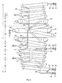
- Figure 1 shows the present invention in a stacked configuration with vertical bore access to a surface vessel using an intervention riser.
- An advantage of using an intervention rise is that it can operate above the maximum well operations pressure.
- a separator package 10, including a toroidal separator 11, and associated spiral conduits 12, 13, are mounted around a spool body 14, having a bore extending from the surface (not shown), through an intervention riser 16, and an emergency disconnect package 17, spool body 14, the separator package, and into a spool tree 18 and, ultimately, into a subsea well.
- the well is provided, at its upper end, with a wellhead assembly 20 and is connected to the spool tree 18.
- the spool body 14 is provided with numerous rams including coil tubing gripping rams 21, lower rams 22 and upper shear/blind rams 23.
- the lower rams 22 may be coil tubing, cable or wire line rams.
- the shear/blind rams are designed such that, when operated, they can cut through the coil tubing 9 logging cable or wire line within the riser and provide a single pressure mechanical isolating barrier between the pressurised production fluid and the surface.
- An annular 24 and a stripping annular 30 are provided above the rams and upper 25 and lower 26 production barrier valves are located respectively above and below the rams.
- This configuration allows the surface intervention vessel to run downhole monitoring equipment and to log the well, yet in an emergency can seal, cut, shut down the vertical flow and disconnect the intervention riser.
- a production fluid take-off 29 from the bore 15 passes through a multi-phase valve 27 and a multi-phase choke 28 into the main bore 40 of the separator 11.
- Fig. 2 shows a toroidal separator 11 having a main bore 40 which is provided with exit lines 41 and 42 for heavier and lighter fluids respectively.
- the exit line 41 is tangential to the bottom circumference of the bore 40 and is mounted on the lower outer portion of the bore.
- the exit line 42 for lighter fluids is mounted tangentially to the upper inner portion of the bore 40.
- the location of the outlet is, of course, dependent on the actual flow which is expected to pass around the bore and therefore the location of the connections of the exit lines can be changed without effecting the operation of the invention.
- the separator 11 is divided into a number of different interlinking areas, a gas stabilisation section 43, a gas toroidal 44, a liquid toroidal section 45, a liquid stabilising section 46, an oil separation section 47 and a solids removal section 48.
- the usual medium would comprise a combination of sand and other solids, gaseous or liquid hydrocarbons, and water.
- the multi-phase flow production enters the main bore 40 through inlet 49 and is separated into wet gas, that is mainly gas but with entrained liquid, which exits through exit line 42, and solids, liquid hydrocarbons such as oil, water and a little entrained gas which exit the bore 40 through exit line 41.
- the wet gas travels upwardly through the gas spiral toroidal 44 and a spiral conduit 50, with the pressure/flow rate controlled by a choke 51 which is on the downstream side of gas sensors 52 and a gas isolation valve 53.
- the liquid within the wet gas is forced into the outer wall of the gas toroidal 44 and the conduit 50 and collects.
- liquid drain pipes 54 are provided to direct any liquid which has been separated from the gas flow back into a liquid toroidal 60.
- any entrained gas is separated to the inner upper portion of the conduit and is separated off via exit lines 62 and is directed into the gas toroidal 44.
- the fluid passes further down through the conduit, and the gas is removed, it is the oil which moves to the upper inner portion and this is separated off via exit lines 63 into a common pathway 64, which subsequently passes, via oil sensors 65 and an oil isolation valve 66 through an oil choke 67.
- the sand/solids slurry containing some residual liquid and any sand or solids entrained in the flow, pass out of the spiral conduit via a solid slurry line 68, past a solids sensor 69, a solids isolation valve 70 and through a solids choke 71.
- the remaining water is channelled through a water exit line 72 past water sensors 73, a water isolation valve 74 and through the water choke 75.
- Fig 1 shows a vertical well production test configuration to a surface vessel being either a drilling vessel or a dedicated intervention well test vessel.
- This configuration can be installed using a intervention riser 16 capable of containing the maximum well operating pressure by using a drilling vessel or a well test/intervention vessel.
- Each of the exit lines from the separator II for gas, oil, water and solids is connected to a respective pump 76, 77, 78, 79 for delivering the separated phases to the surface depending on the separator operating pressure.
- the choke line 80 can be connected to the gas pump 76 to deliver the separated gas to the surface.
- the outlets from the water 78 and solids 79 pumps are joined to deliver the water/solids, via the intervention riser line 81 to the surface.
- the separated oil is delivered via oil supply line 82 back into the bore 15, above the upper production barrier valve 25, for delivery to the surface.
- the separated phases can be admitted for further separation using a second or third separator.
- additional tubular bores can be provided as part of one or each exit line, thereby providing additional separation before the spiral conduits.
- a booster line 83 on the intervention 16 is used to provide drive fluid to power the pumps, with exhaust drive fluid returning up the riser line 84, although the pumps could, alternatively, be powered electrically.
- Fig 3 shows a configuration that can be deployed by a drilling vessel using a heavy low pressure drilling riser 89 that does not require a dedicated intervention riser 16.
- the riser which is attached to the emergency disconnection package 17 is a low pressure drilling riser 89 and, as such, the drive fluid can be exhausted back into the main drilling riser, rather than requiring a separate line, with the coil tubing, cable or wire line 9, as well as the separated oil, passing through a tubular pipe 88 within the riser.
- the tubular pipe 88 can be drill pipe, tubing or casing of a suitable diameter and capable of containing above the maximum well bore pressure.
- the production test system can be run and connected up using the drilling riser 89.
- the drilling vessel can then run and lock the tubular pipe into the body of the emergency disconnect package connector 87 to achieve full well access.
- the riser lines 80, 81, 83 and 84 are shown as part of the riser but could equally be flexible lines hung from the surface vessel and connected to the emergency disconnect package 17.
- test module can be positioned adjacent the tree and connected up, either in the stacked configuration in Figs. 2 and 3 or alternatively and as shown in Figs. 4 and 5 in a side-by-side arrangement.
- the appropriate flow lines can connect the test module to the field manifold such that, once installed and flowing, the field support vessel can depart.
- Figs. 4 and 5 show side-by-side configurations, with the separator package 10, emergency disconnect 17 and riser 16 mounted on a firm base, such as a pile 100, within the sea bed and connected to a spool tree, in this case, a conventional spool tree 18 or any type of subsea production tree via a bridging line 101, through which all the necessary fluids can be caused to flow in individual lines.
- a spool tree in this case, a conventional spool tree 18 or any type of subsea production tree via a bridging line 101, through which all the necessary fluids can be caused to flow in individual lines.
- the riser can be removed as it merely provides the means for getting the necessary fluids to the production test vessel and, subsequently, passing the separated phases from the multi-phase medium back to the surface.
- the separator package 10 in Fig 5 could also be used in the Fig 1 configuration directly connected to the spool tree 18. This allows the system to flow to a subsea field system or using a flexible bundle instead of a rigid bundle 110 to the surface being either the drilling rig or intervent vessel or a separate production flow test vessel and allowing the surface vessel to depart. The main purpose of this is to flow test the system which is independent of the subsea tree.
- Fig. 6A represents an external cap flow test spool tree
- Fig. 6B shows an internal cap flow test spool tree.
- a spool tree 18 is connected and sealed to a well head 20 comprising of a connector 121 and a spool body 122.
- a orientated tubing hanger 123 is supported at a precise elevation in the spool body 122.
- a lateral production port 124 provides a path for the well fluid to flow to a production master valve 125, then through a production isolation valve 126, and into a pipeline (not shown).
- tubing hanger 123 In the main vertical bore of the tubing hanger 123, above the lateral port 124, are two independent closure members 130, 131.
- the tubing hanger is provided with its own mechanical locking system to the spool body 132 and above is a second mechanical lock system 133 providing a dual independent lockdown system.
- a lateral port 140 connects to an annulus master valve 141, an annulus isolation valve 142 and to an annulus pipeline (not shown).
- a crossover line with a crossover valve 144 provides a fluid path between the annulus and production pipework.
- An annulus workover path with an annulus workover valve 145 communicates with the spool body bore 150 below the top of the spool body 122.
- a production port 151 communicates with the spool body bore 150 between the workover port 146 and the top of the tubing hanger 123.
- Fig 6a shows a external tree cap 160 with a external connector 161 connecting and sealing to the hub profile of the spool body 122. Monitoring and venting ports are provided to access the workover port 146 and the production port 151.
- the tree cap 160 provides a total seal to the spool body bore 150 and a internal cap seal 164 prevents fluid communication between workover port 146 and production port 151.
- the separator 10 has a connector with a internal arrangement similar to the tree cap 160 that allows vertical independent production and annulus communication between the spool tree 18 and the separator 10.
- Figure 6b shows the use of a internal tree cap 170 that locks and seals to the internal bore of the spool body 122.
- the internal tree cap 170 has a production/annulus isolation seal between the production port 151 and the annulus port 146.
- the spool tree will provide double mechanical pressure isolation of the well bore with or without the tree caps 160, 170 in place and when the separator 10 is connected.
- closure members 130, 131 When direct well access is required, the closure members 130, 131 have to be opened or removed and the valve and ram barriers in the separator 10 will become the prime isolation barriers.
Abstract
Description
- This invention relates to a subsea well production flow system and to a method of production testing and recording downhole characteristics in a subsea well. In particular, the invention relates to a method and system which assist in the determination of the quality and amount of products, such as gaseous or liquid hydrocarbons, produced by the well while at the same time logging the well to identify the rate of flow over the producing formation sections.
- When a new production well is drilled and completed, it is necessary to flow test the well to evaluate its performance and flow characteristics from different intervals of the well. In an existing field, the well can be connected to the field seabed infrastructure and flowed back individually along the field's dedicated test line to the surface production installation on the surface installation, the well fluids can be separated and analysed for, amongst other things, flow rate, density and composition while at the same time carrying out a well intervention to monitor the downhole characteristics using a separate intervention vessel.
- There are numerous disadvantages to this approach. Firstly, the subsea field infrastructure requires an individual and separate test line. Secondly, the new production well must be close to a field connection point and subsequently has to be connected to that connection point. Thirdly, the well must have sufficient energy to supply the fluid to the surface for the analysis to be carried out. Fourthly, a separate operation is required to access the well.
- Other situations in which it is advantageous to flow test a well are on exploration wells, appraisal wells or early development wells to evaluate the production capabilities prior to installation of the flow lines or for production wells where there are no means to flow the well individually. All of these may be situations in which there is no field into which the fluid can be supplied. Currently, in order to flow test any of the above wells, it is necessary to provide either a drilling vessel or a work over vessel, together with a riser system in which the fluids from the well can be delivered to the surface, where they can be processed by a portable test separator on the deck of the respective vessels.
- The disadvantages of the known arrangements are that the well must have sufficient energy to flow to the surface and, as a significant number of wells will not flow naturally to the surface, these cannot be tested.
- Typically, the duration of a flow test depends upon the required degree of investigation, but last for at least two to three days, but could be for as long as several months. Quite clearly, the longer the flow test is carried out for, the better the fields reservoir performance can be estimated, but this can, of course, be extremely costly. For a long test, a surface vessel is required which is expensive, time consuming and entirely dependent on having suitable weather conditions on the surface for the duration of the test. The key factor is to monitor the draw down of the reservoir by continuously flowing the well, and preferably to use continuous monitoring equipment suspended in the well or by carrying our periodic well production logging operations.
- According to the present invention, there is provided a method of production flowing a subsea well, the method comprising the steps of:
- supplying a multi-phase medium from a subsea tree to a removable separator package;
- separating the multi-phase flow into one or more phases at the desired pressures, the pressures being controlled by one or more pressure control devices on one or more outlets from the separator package; and
- analysing each of the one or more phases to determine the amount and quality of products produced by the well.
- In this way, the present invention allows the individual phases within the fluids produced by a well to be continuously tested and analysed either subsea or at the surface when a vessel is on the well.
- When there is sufficient field infrastructure in place to connect the well production test system to, it will allow the well bore surface intervention vessel to depart and possibly return at periodic periods over the production test duration if monitoring equipment is not installed in the well. Alternatively, it could remain in place as an early production system.
- For subsea this avoids the need for a continuous surface intervention installation which, as described above, are costly, complex and not always suitable for all fields.
- Preferably, the multi-phase flow is separated by passing the flow into a toroidal separator. Such a toroidal separator provides a suitable separator which can be mounted in a subsea separator package, such that the fluids can piped individually to the surface, or can be commingled into either a rigid riser, flexible riser, or one or more flow lines. If the well does not have sufficient drive on its own to the seabed, artificial lift, such as gas lift, can assist the well to deliver the multi phase fluid to the production flow test system.
- By providing pressure control devices on the outlets from the separator package, the separator can be operated at below ambient seawater pressure, or below the well fluid's hydrostatic pressure at the seabed, but will therefore require one or more pumps to carry the individual phases to the surface. This will allow a greater range of separation and a more detailed analysis of the performance of the well. Additionally, being able to lower the pressure considerably below the seawater ambient pressure, or below the well fluid's hydrostatic pressure at the seabed, will quickly allow the well to be brought on for a well that has insufficient energy. For low pressure wells this could be a process which can sometimes take several days, especially if the well has previously been killed by bullheading prior to a workover.
- The present invention also provides a system for use in flow testing a subsea well, the system comprising:
- a subsea tree for, in use, connection to a wellhead;
- a separator package in fluid communication with a fluid take off from the subsea tree, such that, in use, a multi-phase medium can flow from the subsea tree into the separator for separation into one or more phases; and
- a pressure control device on each of one or more outlets from the separator package for allowing the system to be operated at different wellhead pressures.
- The separator package may be located adjacent the subsea tree or, alternatively, may be mounted above the tree, to allow vertical access through the separator package and into the subsea tree.
- Examples of the present invention will now be described with reference to the accompanying drawings, in which:
-
Fig. 1 shows a schematic side view of a stacked configuration of the present invention with an intervention riser; -
Fig. 2 shows a schematic toroidal separator suitable for use in the present invention; -
Fig. 3 is a schematic side view of the stacked configuration using a low pressure drilling riser and a maximum well operating pressure internal riser; -
Fig. 4 shows the present invention in a side-by-side arrangement but flowing up a intervention riser; -
Fig. 5 shows a further example of a side-by-side arrangement flow into a pipeline bundle; and -
Figs. 6A and B show external and internal caps for a spool tree for use in the present invention. -
Figure 1 shows the present invention in a stacked configuration with vertical bore access to a surface vessel using an intervention riser. An advantage of using an intervention rise is that it can operate above the maximum well operations pressure. Aseparator package 10, including atoroidal separator 11, and associatedspiral conduits spool body 14, having a bore extending from the surface (not shown), through anintervention riser 16, and anemergency disconnect package 17,spool body 14, the separator package, and into aspool tree 18 and, ultimately, into a subsea well. The well is provided, at its upper end, with awellhead assembly 20 and is connected to thespool tree 18. - The
spool body 14 is provided with numerous rams including coiltubing gripping rams 21,lower rams 22 and upper shear/blind rams 23. Thelower rams 22 may be coil tubing, cable or wire line rams. The shear/blind rams are designed such that, when operated, they can cut through thecoil tubing 9 logging cable or wire line within the riser and provide a single pressure mechanical isolating barrier between the pressurised production fluid and the surface. An annular 24 and a stripping annular 30 are provided above the rams and upper 25 and lower 26 production barrier valves are located respectively above and below the rams. - This configuration allows the surface intervention vessel to run downhole monitoring equipment and to log the well, yet in an emergency can seal, cut, shut down the vertical flow and disconnect the intervention riser.
- A production fluid take-off 29 from the
bore 15 passes through amulti-phase valve 27 and amulti-phase choke 28 into themain bore 40 of theseparator 11. -
Fig. 2 shows atoroidal separator 11 having amain bore 40 which is provided withexit lines exit line 41 is tangential to the bottom circumference of thebore 40 and is mounted on the lower outer portion of the bore. Theexit line 42 for lighter fluids is mounted tangentially to the upper inner portion of thebore 40. The location of the outlet is, of course, dependent on the actual flow which is expected to pass around the bore and therefore the location of the connections of the exit lines can be changed without effecting the operation of the invention. - The
separator 11 is divided into a number of different interlinking areas, agas stabilisation section 43, a gas toroidal 44, a liquidtoroidal section 45, aliquid stabilising section 46, anoil separation section 47 and asolids removal section 48. The usual medium would comprise a combination of sand and other solids, gaseous or liquid hydrocarbons, and water. In this example, the multi-phase flow production enters themain bore 40 throughinlet 49 and is separated into wet gas, that is mainly gas but with entrained liquid, which exits throughexit line 42, and solids, liquid hydrocarbons such as oil, water and a little entrained gas which exit thebore 40 throughexit line 41. - The wet gas travels upwardly through the gas
spiral toroidal 44 and aspiral conduit 50, with the pressure/flow rate controlled by achoke 51 which is on the downstream side ofgas sensors 52 and agas isolation valve 53. The liquid within the wet gas is forced into the outer wall of thegas toroidal 44 and theconduit 50 and collects. At certain points in the outer wall of thetoroidal 44 andconduit 50,liquid drain pipes 54 are provided to direct any liquid which has been separated from the gas flow back into aliquid toroidal 60. The multi-phase liquid having trapped gas, which exits throughexit line 41, passes, via a liquid toroidal 60, into theliquid stabilisation section 46, which is the upper portion of aspiral conduit 61. As the liquid spirals down the conduit, any entrained gas is separated to the inner upper portion of the conduit and is separated off viaexit lines 62 and is directed into thegas toroidal 44. As the fluid passes further down through the conduit, and the gas is removed, it is the oil which moves to the upper inner portion and this is separated off viaexit lines 63 into acommon pathway 64, which subsequently passes, viaoil sensors 65 and anoil isolation valve 66 through anoil choke 67. - At the lowermost end of the
spiral conduit 61, the sand/solids slurry, containing some residual liquid and any sand or solids entrained in the flow, pass out of the spiral conduit via asolid slurry line 68, past asolids sensor 69, asolids isolation valve 70 and through asolids choke 71. The remaining water is channelled through awater exit line 72past water sensors 73, awater isolation valve 74 and through thewater choke 75. -
Fig 1 shows a vertical well production test configuration to a surface vessel being either a drilling vessel or a dedicated intervention well test vessel. This configuration can be installed using aintervention riser 16 capable of containing the maximum well operating pressure by using a drilling vessel or a well test/intervention vessel. - Each of the exit lines from the separator II for gas, oil, water and solids is connected to a
respective pump choke line 80 can be connected to thegas pump 76 to deliver the separated gas to the surface. The outlets from thewater 78 andsolids 79 pumps are joined to deliver the water/solids, via theintervention riser line 81 to the surface. The separated oil is delivered viaoil supply line 82 back into thebore 15, above the upperproduction barrier valve 25, for delivery to the surface. - If higher levels of separation are required, the separated phases can be admitted for further separation using a second or third separator. Alternatively, additional tubular bores can be provided as part of one or each exit line, thereby providing additional separation before the spiral conduits.
- In a preferred example a
booster line 83 on theintervention 16 is used to provide drive fluid to power the pumps, with exhaust drive fluid returning up theriser line 84, although the pumps could, alternatively, be powered electrically. -
Fig 3 shows a configuration that can be deployed by a drilling vessel using a heavy lowpressure drilling riser 89 that does not require adedicated intervention riser 16. - The riser which is attached to the
emergency disconnection package 17 is a lowpressure drilling riser 89 and, as such, the drive fluid can be exhausted back into the main drilling riser, rather than requiring a separate line, with the coil tubing, cable orwire line 9, as well as the separated oil, passing through atubular pipe 88 within the riser. - The
tubular pipe 88 can be drill pipe, tubing or casing of a suitable diameter and capable of containing above the maximum well bore pressure. The production test system can be run and connected up using thedrilling riser 89. The drilling vessel can then run and lock the tubular pipe into the body of the emergencydisconnect package connector 87 to achieve full well access. - Once the fluids are on the surface vessel, they are handled in the same manner as a surface flow test albeit at a reduced pressure.
- The riser lines 80, 81, 83 and 84 are shown as part of the riser but could equally be flexible lines hung from the surface vessel and connected to the
emergency disconnect package 17. - Using a field support vessel with lifting capability, the test module can be positioned adjacent the tree and connected up, either in the stacked configuration in
Figs. 2 and3 or alternatively and as shown inFigs. 4 and5 in a side-by-side arrangement. The appropriate flow lines can connect the test module to the field manifold such that, once installed and flowing, the field support vessel can depart. -
Figs. 4 and5 show side-by-side configurations, with theseparator package 10,emergency disconnect 17 andriser 16 mounted on a firm base, such as apile 100, within the sea bed and connected to a spool tree, in this case, aconventional spool tree 18 or any type of subsea production tree via abridging line 101, through which all the necessary fluids can be caused to flow in individual lines. In this arrangement, there is, clearly, no direct vertical access to the well. The riser can be removed as it merely provides the means for getting the necessary fluids to the production test vessel and, subsequently, passing the separated phases from the multi-phase medium back to the surface. This can, of course, be done via additional pipe lines bundles 110 which connect into the main field, via a manifold (not shown). Such an arrangement is shown inFig. 5 . This configuration allows direct vertical well intervention to thespool tree 18 or other type of subsea production tree independent of the well processing operation. - The
separator package 10 inFig 5 could also be used in theFig 1 configuration directly connected to thespool tree 18. This allows the system to flow to a subsea field system or using a flexible bundle instead of arigid bundle 110 to the surface being either the drilling rig or intervent vessel or a separate production flow test vessel and allowing the surface vessel to depart. The main purpose of this is to flow test the system which is independent of the subsea tree. - Two examples of spool trees which can be utilised in the arrangement in
Figs.1 ,2 or3 are shown inFig. 6A and 6B. Fig. 6A represents an external cap flow test spool tree andFig. 6B shows an internal cap flow test spool tree. - To prevent the requirements to remotely connect flow lines from the
spool tree 18 to theseparator 10, to achieve vertical flow, two variations of the spool tree are suggested. This will enable the spool tree to provide double mechanical isolation barriers to the well flow. - A
spool tree 18 is connected and sealed to awell head 20 comprising of aconnector 121 and aspool body 122. A orientatedtubing hanger 123 is supported at a precise elevation in thespool body 122. Alateral production port 124 provides a path for the well fluid to flow to aproduction master valve 125, then through aproduction isolation valve 126, and into a pipeline (not shown). - In the main vertical bore of the
tubing hanger 123, above thelateral port 124, are twoindependent closure members spool body 132 and above is a secondmechanical lock system 133 providing a dual independent lockdown system. - Below the
tubing hanger 123 from the annulus, between thetubing 19 and thespool body 122, alateral port 140 connects to anannulus master valve 141, anannulus isolation valve 142 and to an annulus pipeline (not shown). A crossover line with acrossover valve 144 provides a fluid path between the annulus and production pipework. An annulus workover path with anannulus workover valve 145 communicates with the spool body bore 150 below the top of thespool body 122. Aproduction port 151 communicates with the spool body bore 150 between theworkover port 146 and the top of thetubing hanger 123. -
Fig 6a shows aexternal tree cap 160 with aexternal connector 161 connecting and sealing to the hub profile of thespool body 122. Monitoring and venting ports are provided to access theworkover port 146 and theproduction port 151. Thetree cap 160 provides a total seal to the spool body bore 150 and ainternal cap seal 164 prevents fluid communication betweenworkover port 146 andproduction port 151. - In
Figure 1 , theseparator 10 has a connector with a internal arrangement similar to thetree cap 160 that allows vertical independent production and annulus communication between thespool tree 18 and theseparator 10. -
Figure 6b shows the use of ainternal tree cap 170 that locks and seals to the internal bore of thespool body 122. Theinternal tree cap 170 has a production/annulus isolation seal between theproduction port 151 and theannulus port 146. - In this arrangement, the spool tree will provide double mechanical pressure isolation of the well bore with or without the tree caps 160, 170 in place and when the
separator 10 is connected. - When direct well access is required, the
closure members separator 10 will become the prime isolation barriers.
Claims (17)
- A method of flowing a subsea well, the method comprising the steps of:supplying a multi-phase medium from a subsea tree to a removable separator package;separating the multi-phase flow into one or more phases at the desired pressures, the pressure being controlled by one or more pressure control devices on one or more outlets from the separator package;analysing each of the one or more phases to determine the amount and quality of products produced by the well.
- A method according to claim 1, wherein the analysis is carried out subsea.
- A method according to claim 1, wherein the analysis is carried out at the surface.
- A method according to claim 1, wherein the pressure of one or more of the constituent phases is reduced to surface or atmospheric pressure.
- A method according to claim 4, wherein the pressure to which one or more phases is/are reduced to below the hydrostatic pressure in the bore at the seabed.
- A method according to any one of the preceding claims, further comprising the step of pumping one or more of the constituent phases to the analysis location.
- A method according to any one of the preceding claims, wherein the separation of the multiphase flow is carried out by a toroidal separator.
- A system for use in flowing a sea well, the system comprising:a subsea tree for, in use, connection to a wellhead;a separator package in fluid communication with a fluid take off from the subsea tree, such that, in use, a multi-phase medium can flow through the subsea tree into the separator for separation into one or more phases;a pressure control device on each of one or more outlets from the separator package for allowing the system to be operated at different wellhead pressures.
- A system according to claim 8, wherein the separator package includes a toroidal separator.
- A system according to either claim 8 or claim 9, wherein the separator package is substantially vertically aligned with the subsea tree.
- A system according to either claim 8 or claim 9, wherein the separator package is placed adjacent to the subsea tree.
- A system according to any one of claims 8 to 11, further comprising a pressure containing device for containing the pressure of the fluid from within the tree, whilst permitting wire line, cable or coil tubing access through the tree.
- A system according to any one of claims 8 to 12, wherein the pressure control device is either a choke or a pump.
- A system according to any one of claims 8 to 13, further comprising valves and a ram isolation package to facilitate a reduction in the pressure in the well bore when required.
- A system according to any one of claims 8 to 14, further comprising an emergency disconnect package.
- A system according to any one of claims 8 to 15, wherein the outlets from the separator package are connected to flow lines in pre-existing subsea infrastructure.
- A system according to any one of claims 7 to 13, wherein the outlets from the separator package are connected to individual flow lines to the surface.
Applications Claiming Priority (1)
| Application Number | Priority Date | Filing Date | Title |
|---|---|---|---|
| EP03256021A EP1518595B1 (en) | 2003-09-24 | 2003-09-24 | Subsea well production flow and separation system |
Related Parent Applications (1)
| Application Number | Title | Priority Date | Filing Date |
|---|---|---|---|
| EP03256021.1 Division | 2003-09-24 |
Publications (2)
| Publication Number | Publication Date |
|---|---|
| EP2283905A2 true EP2283905A2 (en) | 2011-02-16 |
| EP2283905A3 EP2283905A3 (en) | 2011-04-13 |
Family
ID=34178624
Family Applications (2)
| Application Number | Title | Priority Date | Filing Date |
|---|---|---|---|
| EP03256021A Expired - Lifetime EP1518595B1 (en) | 2003-09-24 | 2003-09-24 | Subsea well production flow and separation system |
| EP10178233A Withdrawn EP2283905A3 (en) | 2003-09-24 | 2003-09-24 | Subsea well production flow and separation system |
Family Applications Before (1)
| Application Number | Title | Priority Date | Filing Date |
|---|---|---|---|
| EP03256021A Expired - Lifetime EP1518595B1 (en) | 2003-09-24 | 2003-09-24 | Subsea well production flow and separation system |
Country Status (5)
| Country | Link |
|---|---|
| US (1) | US7363982B2 (en) |
| EP (2) | EP1518595B1 (en) |
| BR (1) | BRPI0403993B1 (en) |
| NO (1) | NO333329B1 (en) |
| SG (1) | SG110118A1 (en) |
Families Citing this family (35)
| Publication number | Priority date | Publication date | Assignee | Title |
|---|---|---|---|---|
| EP2216503B1 (en) | 2003-05-31 | 2013-12-11 | Cameron Systems (Ireland) Limited | Apparatus and method for recovering fluids from a well and/or injecting fluids into a well |
| CA2555403C (en) * | 2004-02-26 | 2012-08-21 | Des Enhanced Recovery Limited | Connection system for subsea flow interface equipment |
| US7331396B2 (en) * | 2004-03-16 | 2008-02-19 | Dril-Quip, Inc. | Subsea production systems |
| NO326586B1 (en) * | 2005-05-02 | 2009-01-12 | Norsk Hydro As | Pipe separator. |
| US7686086B2 (en) * | 2005-12-08 | 2010-03-30 | Vetco Gray Inc. | Subsea well separation and reinjection system |
| US7569097B2 (en) * | 2006-05-26 | 2009-08-04 | Curtiss-Wright Electro-Mechanical Corporation | Subsea multiphase pumping systems |
| GB0618001D0 (en) | 2006-09-13 | 2006-10-18 | Des Enhanced Recovery Ltd | Method |
| GB0625191D0 (en) | 2006-12-18 | 2007-01-24 | Des Enhanced Recovery Ltd | Apparatus and method |
| GB0625526D0 (en) | 2006-12-18 | 2007-01-31 | Des Enhanced Recovery Ltd | Apparatus and method |
| NO337029B1 (en) * | 2008-04-25 | 2016-01-04 | Vetco Gray Inc | Device for separating water for use in well operations |
| BR112012009724A2 (en) * | 2009-10-27 | 2016-05-17 | Shell Int Research | method for separating a multiphase fluid, separation system for a multiphase fluid, subsea and platform processing assemblies, methods for separating solid particles and for separating a multiphase fluid stream, and apparatus for separating a multiphase fluid stream |
| WO2011079319A2 (en) * | 2009-12-24 | 2011-06-30 | Wright David C | Subsea technique for promoting fluid flow |
| GB2479915B (en) * | 2010-04-29 | 2016-03-23 | Ge Oil & Gas Uk Ltd | Well production shut down |
| US9004176B2 (en) * | 2010-07-21 | 2015-04-14 | Marine Well Containment Company | Marine well containment system and method |
| US9371724B2 (en) | 2012-07-27 | 2016-06-21 | Exxonmobil Upstream Research Company | Multiphase separation system |
| US9320989B2 (en) | 2013-03-15 | 2016-04-26 | Haven Technology Solutions, LLC. | Apparatus and method for gas-liquid separation |
| US9932732B1 (en) * | 2013-05-20 | 2018-04-03 | Thermaco, Inc. | Passive grease trap with lift system |
| WO2015018945A2 (en) | 2013-08-09 | 2015-02-12 | Linde Aktiengesellschaft | Subsea well stream treatment |
| EP3097262B1 (en) | 2014-01-24 | 2019-10-09 | Cameron Technologies Limited | Systems and methods for polymer degradation reduction |
| SG11201606687TA (en) | 2014-03-12 | 2016-09-29 | Exxonmobil Upstream Res Co | Split flow pipe separator with sand trap |
| BR112016016005A2 (en) | 2014-04-29 | 2016-10-18 | Exxonmobil Upstream Res Co | polyphase separation system |
| SG11201702668RA (en) | 2014-11-17 | 2017-06-29 | Exxonmobil Upstream Res Co | Liquid collection system |
| CN106474828A (en) | 2015-08-27 | 2017-03-08 | 通用电气公司 | Apparatus and method for Gravity Separation and the oil and natural gas production system comprising which and method |
| CN106861294A (en) * | 2015-12-10 | 2017-06-20 | 通用电气公司 | For separating the apparatus and method of fluid and the hydrocarbon production system comprising it and method |
| WO2017218596A1 (en) * | 2016-06-13 | 2017-12-21 | Trendsetter Vulcan Offshore, Inc. | Early production system for deep water application |
| NO344641B1 (en) * | 2016-07-06 | 2020-02-17 | Aker Solutions As | Subsea methane production assembly |
| GB2573212B (en) | 2016-08-19 | 2020-02-19 | Fourphase As | Solid particle separation in oil and/or gas production |
| NO344597B1 (en) * | 2016-10-31 | 2020-02-03 | Bri Cleanup As | Method and apparatus for processing fluid from a well |
| NO344601B1 (en) * | 2016-10-31 | 2020-02-10 | Bri Cleanup As | Assembly for an oil and gas production platform or rig, and related methods |
| US10267124B2 (en) | 2016-12-13 | 2019-04-23 | Chevron U.S.A. Inc. | Subsea live hydrocarbon fluid retrieval system and method |
| FR3063912B1 (en) * | 2017-03-20 | 2021-11-05 | Dcns | FLUID PURIFICATION SYSTEM, STEAM GENERATOR AND ELECTRICAL ENERGY PRODUCTION PLANT |
| US11253804B2 (en) * | 2018-06-01 | 2022-02-22 | Mobiair Pte. Ltd. | Apparatus and method to clean particle loaded fluid using low energy multi-flow splitter technology requiring no filter media |
| US10478753B1 (en) | 2018-12-20 | 2019-11-19 | CH International Equipment Ltd. | Apparatus and method for treatment of hydraulic fracturing fluid during hydraulic fracturing |
| MX2021007541A (en) | 2018-12-20 | 2021-10-13 | Haven Tech Solutions Llc | Apparatus and method for gas-liquid separation of multi-phase fluid. |
| AT18039U1 (en) * | 2022-07-14 | 2023-11-15 | Engel Austria Gmbh | Hydraulic line system for at least partial separation and shaping machine and method therefor |
Family Cites Families (45)
| Publication number | Priority date | Publication date | Assignee | Title |
|---|---|---|---|---|
| GB499024A (en) | 1936-05-14 | 1939-01-16 | Juan Loumiet Et Lavigne | Improvements in or relating to centrifugal separation |
| US2468070A (en) | 1944-11-18 | 1949-04-26 | James F Hunter | Liquid separation apparatus |
| US3346117A (en) | 1965-06-09 | 1967-10-10 | Texaco Inc | De-emulsifying apparatus |
| US3543846A (en) * | 1968-11-18 | 1970-12-01 | Westinghouse Electric Corp | Underwater oil or gas facility |
| US3545215A (en) | 1968-12-05 | 1970-12-08 | Combustion Eng | Field processing equipment for oil wells mounted at a subsea location |
| US4175039A (en) | 1978-01-30 | 1979-11-20 | Fisher Johnny D | Washer/separator system for drilling cuttings in water environment oil wells |
| FR2528106A1 (en) * | 1982-06-08 | 1983-12-09 | Chaudot Gerard | SYSTEM FOR THE PRODUCTION OF UNDERWATER DEPOSITS OF FLUIDS, TO ALLOW THE PRODUCTION AND TO INCREASE THE RECOVERY OF FLUIDS IN PLACE, WITH FLOW REGULATION |
| US4438817A (en) * | 1982-09-29 | 1984-03-27 | Armco Inc. | Subsea well with retrievable piping deck |
| GB8707306D0 (en) | 1987-03-26 | 1987-04-29 | British Petroleum Co Plc | Underwater oilfield separator |
| US5004442A (en) | 1988-06-27 | 1991-04-02 | Lemelson Jerome H | Educational toys |
| US5004051A (en) | 1989-09-12 | 1991-04-02 | Norwegian Contracts A/S | Method and means for cleansing and storing drill cuttings from drilling operations in the sea bottom |
| US4955436A (en) | 1989-12-18 | 1990-09-11 | Johnston Vaughn R | Seal apparatus |
| NO900500D0 (en) * | 1990-02-02 | 1990-02-02 | Kvaerner Subsea Contracting | PROCEDURE FOR UNDERWATER ROUTE TRANSPORTATION OF HYDROCARBON FLOWERS AA HINTER HYDRATE CREATION, AND UNDERWATER PLANT FOR PROCESSING A BROWN CURRENT FOR AA HIDDEN HYDRATE CREATION. |
| US5004552A (en) | 1990-06-14 | 1991-04-02 | Al Yazdi Ahmed M | Apparatus and method for separating water from crude oil |
| BR9003370A (en) * | 1990-07-13 | 1992-01-21 | Petroleo Brasileiro Sa | OIL AND GAS PRODUCTION SYSTEM IN DEEP WATERS |
| NO172702C (en) * | 1991-02-08 | 1993-08-25 | Kvaerner Rosenberg As Kvaerner | INSTALLATION FOR TESTING A BROWN STREAM, SPECIAL ON THE SEA |
| US5248421A (en) | 1992-10-09 | 1993-09-28 | The United States Of America As Respresented By The Administrator Of The National Aeronautics And Space Administration | Spiral fluid separator |
| US6569323B1 (en) | 1993-02-01 | 2003-05-27 | Lev Sergeevish Pribytkov | Apparatus for separation media by centrifugal force |
| WO1994025729A1 (en) * | 1993-04-27 | 1994-11-10 | Atlantic Richfield Company | Downhole gas-liquid separator for wells |
| US6457540B2 (en) | 1996-02-01 | 2002-10-01 | Robert Gardes | Method and system for hydraulic friction controlled drilling and completing geopressured wells utilizing concentric drill strings |
| CA2271168A1 (en) * | 1996-11-07 | 1998-05-14 | Baker Hughes Limited | Fluid separation and reinjection systems for oil wells |
| US6216799B1 (en) | 1997-09-25 | 2001-04-17 | Shell Offshore Inc. | Subsea pumping system and method for deepwater drilling |
| US6276455B1 (en) * | 1997-09-25 | 2001-08-21 | Shell Offshore Inc. | Subsea gas separation system and method for offshore drilling |
| US6062313A (en) * | 1998-03-09 | 2000-05-16 | Moore; Boyd B. | Expandable tank for separating particulate material from drilling fluid and storing production fluids, and method |
| US6325159B1 (en) | 1998-03-27 | 2001-12-04 | Hydril Company | Offshore drilling system |
| US6129152A (en) | 1998-04-29 | 2000-10-10 | Alpine Oil Services Inc. | Rotating bop and method |
| US6062213A (en) * | 1998-06-16 | 2000-05-16 | Fuisz Technologies Ltd. | Single unit dose inhalation therapy device |
| US6197095B1 (en) * | 1999-02-16 | 2001-03-06 | John C. Ditria | Subsea multiphase fluid separating system and method |
| US6328118B1 (en) | 1999-03-08 | 2001-12-11 | Halliburton Energy Services, Inc. | Apparatus and methods of separation of materials in an under-balanced drilling operation |
| GB9921373D0 (en) * | 1999-09-10 | 1999-11-10 | Alpha Thames Limited | Modular sea-bed system |
| US6527054B1 (en) | 1999-09-14 | 2003-03-04 | Deep Vision Llc | Apparatus and method for the disposition of drilling solids during drilling of subsea oilfield wellbores |
| US6578637B1 (en) | 1999-09-17 | 2003-06-17 | Exxonmobil Upstream Research Company | Method and system for storing gas for use in offshore drilling and production operations |
| NO996196D0 (en) * | 1999-12-14 | 1999-12-14 | Aker Eng As | |
| US6269880B1 (en) | 2000-01-27 | 2001-08-07 | Ronald J. Landry | System for removing solids from a well bore |
| GB0011928D0 (en) * | 2000-05-17 | 2000-07-05 | Kellogg Brown & Root Inc | Separation method and apparatus for stream containing multi-phase liquid mixture and entrained particles |
| WO2002031309A2 (en) * | 2000-10-13 | 2002-04-18 | Schlumberger Technology B.V. | Methods and apparatus for separating fluids |
| GB0110398D0 (en) * | 2001-04-27 | 2001-06-20 | Alpha Thames Ltd | Wellhead product testing system |
| WO2003023181A1 (en) | 2001-09-10 | 2003-03-20 | Ocean Riser Systems As | Arrangement and method for regulating bottom hole pressures when drilling deepwater offshore wells |
| GB0124613D0 (en) * | 2001-10-12 | 2001-12-05 | Alpha Thames Ltd | System and method for separating fluids |
| GB0124612D0 (en) * | 2001-10-12 | 2001-12-05 | Alpha Thames Ltd | Single well development system |
| US6966367B2 (en) | 2002-01-08 | 2005-11-22 | Weatherford/Lamb, Inc. | Methods and apparatus for drilling with a multiphase pump |
| NO315912B1 (en) | 2002-02-28 | 2003-11-10 | Abb Offshore Systems As | Underwater separation device for processing crude oil comprising a separator module with a separator tank |
| EP1353038A1 (en) * | 2002-04-08 | 2003-10-15 | Cooper Cameron Corporation | Subsea process assembly |
| US6651745B1 (en) * | 2002-05-02 | 2003-11-25 | Union Oil Company Of California | Subsea riser separator system |
| EP1519002A1 (en) * | 2003-09-24 | 2005-03-30 | Cooper Cameron Corporation | BOP and separator combination |
-
2003
- 2003-09-24 EP EP03256021A patent/EP1518595B1/en not_active Expired - Lifetime
- 2003-09-24 EP EP10178233A patent/EP2283905A3/en not_active Withdrawn
-
2004
- 2004-08-16 SG SG200404736A patent/SG110118A1/en unknown
- 2004-09-14 US US10/940,380 patent/US7363982B2/en active Active
- 2004-09-22 BR BRPI0403993-9A patent/BRPI0403993B1/en not_active IP Right Cessation
- 2004-09-23 NO NO20043990A patent/NO333329B1/en not_active IP Right Cessation
Non-Patent Citations (1)
| Title |
|---|
| None |
Also Published As
| Publication number | Publication date |
|---|---|
| US20050061515A1 (en) | 2005-03-24 |
| BRPI0403993B1 (en) | 2015-08-18 |
| NO333329B1 (en) | 2013-05-06 |
| SG110118A1 (en) | 2005-04-28 |
| EP1518595A1 (en) | 2005-03-30 |
| EP1518595B1 (en) | 2012-02-22 |
| US7363982B2 (en) | 2008-04-29 |
| NO20043990L (en) | 2005-03-29 |
| BRPI0403993A (en) | 2005-05-24 |
| EP2283905A3 (en) | 2011-04-13 |
Similar Documents
| Publication | Publication Date | Title |
|---|---|---|
| EP1518595B1 (en) | Subsea well production flow and separation system | |
| US6179056B1 (en) | Artificial lift, concentric tubing production system for wells and method of using same | |
| US10329860B2 (en) | Managed pressure drilling system having well control mode | |
| US4900433A (en) | Vertical oil separator | |
| US7093661B2 (en) | Subsea production system | |
| US8733436B2 (en) | Apparatus and method for recovering fluids from a well and/or injecting fluids into a well | |
| AU2005229738B2 (en) | Subsea pumping system | |
| US7736133B2 (en) | Capsule for two downhole pump modules | |
| US20050217845A1 (en) | Tubing hanger running tool and subsea test tree control system | |
| AU2003241367B2 (en) | System and method for flow/pressure boosting in subsea | |
| US10428630B2 (en) | Apparatus, system and method for live well artificial lift completion | |
| GB2448211A (en) | Wireline bailing system | |
| RU2756650C1 (en) | Method for complex production of hydrocarbons from oil and gas condensate wells and a system for its implementation | |
| JP2024510716A (en) | Systems and methods for hydrate production | |
| NO313768B1 (en) | Method and arrangement for controlling a downhole separator |
Legal Events
| Date | Code | Title | Description |
|---|---|---|---|
| PUAI | Public reference made under article 153(3) epc to a published international application that has entered the european phase |
Free format text: ORIGINAL CODE: 0009012 |
|
| AC | Divisional application: reference to earlier application |
Ref document number: 1518595 Country of ref document: EP Kind code of ref document: P |
|
| AK | Designated contracting states |
Kind code of ref document: A2 Designated state(s): GB |
|
| PUAL | Search report despatched |
Free format text: ORIGINAL CODE: 0009013 |
|
| AK | Designated contracting states |
Kind code of ref document: A3 Designated state(s): GB |
|
| STAA | Information on the status of an ep patent application or granted ep patent |
Free format text: STATUS: THE APPLICATION IS DEEMED TO BE WITHDRAWN |
|
| 18D | Application deemed to be withdrawn |
Effective date: 20111014 |