EP2282326A2 - Substrate mounting mechanism and substrate processing apparatus using same - Google Patents
Substrate mounting mechanism and substrate processing apparatus using same Download PDFInfo
- Publication number
- EP2282326A2 EP2282326A2 EP10171566A EP10171566A EP2282326A2 EP 2282326 A2 EP2282326 A2 EP 2282326A2 EP 10171566 A EP10171566 A EP 10171566A EP 10171566 A EP10171566 A EP 10171566A EP 2282326 A2 EP2282326 A2 EP 2282326A2
- Authority
- EP
- European Patent Office
- Prior art keywords
- substrate
- elevating member
- mounting table
- substrate mounting
- substrates
- Prior art date
- Legal status (The legal status is an assumption and is not a legal conclusion. Google has not performed a legal analysis and makes no representation as to the accuracy of the status listed.)
- Withdrawn
Links
Images



Classifications
-
- H—ELECTRICITY
- H10—SEMICONDUCTOR DEVICES; ELECTRIC SOLID-STATE DEVICES NOT OTHERWISE PROVIDED FOR
- H10P—GENERIC PROCESSES OR APPARATUS FOR THE MANUFACTURE OR TREATMENT OF DEVICES COVERED BY CLASS H10
- H10P72/00—Handling or holding of wafers, substrates or devices during manufacture or treatment thereof
- H10P72/04—Apparatus for manufacture or treatment
- H10P72/0431—Apparatus for thermal treatment
- H10P72/0434—Apparatus for thermal treatment mainly by convection
-
- G—PHYSICS
- G02—OPTICS
- G02F—OPTICAL DEVICES OR ARRANGEMENTS FOR THE CONTROL OF LIGHT BY MODIFICATION OF THE OPTICAL PROPERTIES OF THE MEDIA OF THE ELEMENTS INVOLVED THEREIN; NON-LINEAR OPTICS; FREQUENCY-CHANGING OF LIGHT; OPTICAL LOGIC ELEMENTS; OPTICAL ANALOGUE/DIGITAL CONVERTERS
- G02F1/00—Devices or arrangements for the control of the intensity, colour, phase, polarisation or direction of light arriving from an independent light source, e.g. switching, gating or modulating; Non-linear optics
- G02F1/01—Devices or arrangements for the control of the intensity, colour, phase, polarisation or direction of light arriving from an independent light source, e.g. switching, gating or modulating; Non-linear optics for the control of the intensity, phase, polarisation or colour
- G02F1/13—Devices or arrangements for the control of the intensity, colour, phase, polarisation or direction of light arriving from an independent light source, e.g. switching, gating or modulating; Non-linear optics for the control of the intensity, phase, polarisation or colour based on liquid crystals, e.g. single liquid crystal display cells
- G02F1/1303—Apparatus specially adapted to the manufacture of LCDs
-
- H—ELECTRICITY
- H10—SEMICONDUCTOR DEVICES; ELECTRIC SOLID-STATE DEVICES NOT OTHERWISE PROVIDED FOR
- H10P—GENERIC PROCESSES OR APPARATUS FOR THE MANUFACTURE OR TREATMENT OF DEVICES COVERED BY CLASS H10
- H10P72/00—Handling or holding of wafers, substrates or devices during manufacture or treatment thereof
- H10P72/70—Handling or holding of wafers, substrates or devices during manufacture or treatment thereof for supporting or gripping
- H10P72/76—Handling or holding of wafers, substrates or devices during manufacture or treatment thereof for supporting or gripping using mechanical means, e.g. clamps or pinches
- H10P72/7604—Handling or holding of wafers, substrates or devices during manufacture or treatment thereof for supporting or gripping using mechanical means, e.g. clamps or pinches the wafers being placed on a susceptor, stage or support
-
- H—ELECTRICITY
- H10—SEMICONDUCTOR DEVICES; ELECTRIC SOLID-STATE DEVICES NOT OTHERWISE PROVIDED FOR
- H10P—GENERIC PROCESSES OR APPARATUS FOR THE MANUFACTURE OR TREATMENT OF DEVICES COVERED BY CLASS H10
- H10P72/00—Handling or holding of wafers, substrates or devices during manufacture or treatment thereof
- H10P72/70—Handling or holding of wafers, substrates or devices during manufacture or treatment thereof for supporting or gripping
- H10P72/76—Handling or holding of wafers, substrates or devices during manufacture or treatment thereof for supporting or gripping using mechanical means, e.g. clamps or pinches
- H10P72/7604—Handling or holding of wafers, substrates or devices during manufacture or treatment thereof for supporting or gripping using mechanical means, e.g. clamps or pinches the wafers being placed on a susceptor, stage or support
- H10P72/7612—Handling or holding of wafers, substrates or devices during manufacture or treatment thereof for supporting or gripping using mechanical means, e.g. clamps or pinches the wafers being placed on a susceptor, stage or support characterised by lifting arrangements, e.g. lift pins
Definitions
- the present invention relates to a substrate mounting mechanism which mounts a substrate used for a flat panel display (FDP), a solar battery, or the like; and a processing system having the same, which performs a process on the substrate mounted by using the substrate mounting mechanism.
- FDP flat panel display
- solar battery or the like
- a substrate processing apparatus which provides a substrate mounting table in a chamber therein and mounts a substrate on the substrate mounting table to process the substrate thereon.
- the substrate is mounted onto and dismounted from the substrate mounting table by allowing lift pins to protrude upwardly and retreat downwardly (see, e.g., Japanese Patent Application Publication No. 2006-344675 ).
- the lift pins are allowed to protrude upwardly and the substrate is transferred onto the protruding lift pins by a transfer arm. Then, the lift pins are retreated downwardly to mount the substrate on the substrate mounting table.
- the lift pins are allowed to protrude upwardly to dismount the substrate from the substrate mounting table. Then, the dismounted substrate is transferred by the transfer arm.
- the process e.g., the film-forming process or the heating process
- the substrate is not directly in contact with the substrate mounting table at the portions thereof where the holes are formed. Accordingly, a heat amount transferred at the portions where the substrate is not directly in contact with the substrate mounting table becomes different from that transferred at the portion where the substrate is directly in contact with the substrate mounting table. For that reason, the in-plane temperature of the substrate becomes non-uniform.
- the present invention provides a substrate mounting mechanism and a substrate processing apparatus using the same, capable of making the in-plane temperature of a substrate uniform.
- a substrate mounting mechanism including: a substrate mounting table for mounting a substrate thereon; a heat source for supplying a heat or a cold heat to the substrate via the substrate mounting table; a substrate elevating member movable having a substrate-supporting portion for supporting an end portion of the substrate, the substrate elevating member being upwardly and downwardly between a first position at which the substrate is mounted on the substrate mounting table and a second position that is located above the first position; and an elevating unit for upwardly and downwardly moving the substrate elevating member.
- the substrate elevating member serves as a part of the substrate mounting table at the first position.
- a substrate processing apparatus including: a vessel for accommodating a substrate therein; and the substrate mounting mechanism of the first aspect.
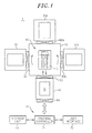
- Fig. 1 is a schematic plan view showing a substrate processing system 1 including a preheating chamber (substrate processing apparatus) in accordance with an embodiment of the present invention.
- the substrate processing system 1 may be a film-forming system which forms a predetermined film on a rectangular substrate, e.g., a glass substrate used for a flat panel display (FPD) such as a liquid crystal display (LCD).
- FPD flat panel display
- LCD liquid crystal display
- the substrate processing system 1 includes a common transfer chamber 10; a preheating chamber 20 constituting a preheating apparatus for preheating a substrate G; processing chambers 30a and 30b, each constituting a film-forming apparatus for forming a predetermined film on the substrate G; a load-lock chamber 40 for switching the substrate G between a substrate container (not shown) disposed in an atmosphere and the common transfer chamber 10 that is maintained in a vacuum state; and a transfer device 50 provided in the common transfer chamber 10 to transfer the substrate G.
- the common transfer chamber 10 is formed in a rectangular shape seen from the top.
- the preheating chamber 20, the processing chambers 30a and 30b, the load-lock chamber 40 are connected to side surfaces of the common transfer chamber 10 through gate valves 61, 62a, 62b, and 63, respectively.
- a gate valve 64 is provided on the atmospheric side of the load-lock chamber 40.
- the common transfer chamber 10 of the present embodiment has the rectangular shape seen from the top as described above, the common transfer chamber 10 may have a polygonal (e.g., hexagonal or octagonal) shape, and the preheating chamber, the processing chamber, and the load-lock chamber may additionally be provided.
- the common transfer chamber 10, the preheating chamber 20, and the processing chambers 30a and 30b are respectively configured as vacuum chambers that are maintained in a predetermined depressurized state. Furthermore, the load-lock chamber 40 is provided to transfer the substrate G between the substrate container (not shown) disposed in the atmosphere and the common transfer chamber 10 maintained in a vacuum state, the load-lock chamber 40 serving as a vacuum prechamber that can be switched between the atmospheric state and the depressurized state.
- the substrate processing system 1 is configured to process at a time a plurality of, e.g., three, substrates G mounted horizontally and arranged above one another in a vertical direction.
- the substrates G are loaded together from the external substrate container into the load-lock chamber 40 through the gate valve 64 by a transfer unit (not shown) in an atmosphere.
- the loaded substrates G are transferred from the load-lock chamber 40 to the common transfer chamber 10, from the common transfer chamber 10 to the preheating chamber 20, and from the preheating chamber 20 to the processing chambers 30a or 30b through the gate valves 63, 61, and 62a or 62b, respectively.
- the substrates G processed in the processing chamber 30a or 30b are transferred from the processing chamber 30a or 30b to the common transfer chamber 10 and from the common transfer chamber 10 to the load-lock chamber 40 through the gate valves 62a or 62b and 63, respectively. Then, the processed substrates G are unloaded from the load-lock chamber 40.
- the processing chambers 30a and 30b may be configured to perform different film-forming processes. In other words, a first film-forming process may be carried out in the processing chamber 30a and, successively, a second film-forming process may be performed in the processing chamber 30b.
- the substrate transfer device 50 serves to transfer the substrates G between the common transfer chamber 10, the preheating chamber 20, the processing chambers 30a and 30b, and the load-lock chamber 40.
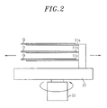
- the substrate transfer device 50 includes a rotatable base member 52; three substrate support arms 51a, 51b and 51c configured to linearly move above the base member 52, the substrate support arms 51a, 51b and 51c being arranged above one another in the vertical direction; and a driving unit 53 for rotating the base member 52.
- the substrate transfer device 50 can allow the substrate support arms 51a to 51c to access the preheating chamber 20, the processing chambers 30a and 30b and the load-lock chamber 40.
- the respective components of the processing system 1 are controlled by a control unit (computer) 70.
- the control unit 70 includes a process controller 71 having a micro processor.
- the process controller 71 is connected to a user interface 72 including a keyboard through which an operator inputs a command or the like to manage the processing system 1, a display unit for visually displaying an operation status of the processing system 1, and the like.
- the process controller 71 is connected to a storage unit 73 which stores therein control programs for realizing various processes performed by the processing system 1 under the control of the process controller 71; and control programs or recipes for performing predetermined processes performed by the processing system 1 under processing conditions.
- the storage unit 73 has a storage medium which stores therein the recipes or the like.
- the storage medium may be a hard disk, a semiconductor memory or a portable storage medium such as a CD-ROM, a DVD, a flash memory or the like. If necessary, a certain recipe is retrieved from the storage unit 73 in response to an instruction from the user interface 72 or the like and is executed by the process controller 71, thereby performing a desired process in the processing system 1 under the control of the process controller 71.
- the gate valve 64 is first opened and a plurality of, e.g., three, substrates G is loaded into the load-lock chamber 40 in the atmospheric state by a substrate transfer device (not shown) disposed in the atmosphere.
- the gate valve 64 is closed, and the inside of the load-lock chamber 40 is set to a depressurized state.
- the gate valve 63 is opened, and the substrate support arms 51a to 51c of the substrate transfer device 50 are moved into the load-lock chamber 40 at a time to take the substrates G loaded to the load-lock chamber 40. Thereafter, the substrate support arms 51a to 51c of the substrate transfer device 50 return to the common transfer chamber 10, and the gate valve 63 is closed.
- the base member 52 of the substrate transfer device 50 is rotated such that the substrate support arms 51a to 51c are positioned to face the preheating chamber 20.
- the gate valve 61 is opened, and the substrate support arms 51a to 51c are moved into the preheating chamber 20 to transfer the substrates G to the preheating chamber 20.
- the substrate support arms 51a to 51c return to the common transfer chamber 10, and the gate valve 61 is closed such that preheating of the substrates G can be started in the preheating chamber 20.
- the gate valve 61 Upon completion of the preheating, the gate valve 61 is opened, and the substrate support arms 51a to 51c are moved into the preheating chamber 20 to take the preheated substrates G. Next, the substrate support arms 51a to 51c return to the common transfer chamber 10, and the gate valve 61 is closed. Then, the base member 52 is rotated such that the substrate support arms 51a to 51c are positioned to face the processing chamber 30a or 30b. Thereafter, the gate valve 62a or 62b is opened, and the substrate support arms 51a to 51c are moved into the processing chamber 30a or 30b to transfer the preheated substrates G to the processing chamber 30a or 30b. Next, the substrate support arms 51a to 51c return to the common transfer chamber 10, and the gate valve 62a or 62b is closed such that processing in the processing chamber 30a or 30b is started.
- the gate valve 62a or 62b is opened, and the substrate support arms 51a to 51c are moved into the processing chamber 30a or 30b to take the processed substrates G. Then, the substrate support arms 51a to 51c return to the common transfer chamber 10, and the gate valve 62a or 62b is closed. Thereafter, the base member 52 is rotated such that the substrate support arms 51a to 51c are positioned to face the load-lock chamber 40. Next, the gate valve 63 is opened, and the substrate support arms 51a to 51c are moved into the load-lock chamber 40 to transfer the processed substrates G to the load-lock chamber 40.
- the substrate support arms 51a to 51c return to the common transfer chamber 10, and the gate valve 63 is closed such that the inside of the load-lock chamber 40 can be set to the atmospheric state. Then, the gate valve 64 is opened, and the processed substrates G are unloaded from the load-lock chamber 40 by the transfer unit (not shown) disposed in the atmosphere.
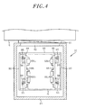
- FIGs. 3 and 4 are a vertical and a horizontal cross sectional view, respectively, showing the preheating chamber 20.
- the preheating chamber 20 includes a vessel 81, and an opening 82 is provided on a sidewall of the vessel 81.
- the preheating chamber 20 can communicate with the common transfer chamber 10 that is maintained in a vacuum state through the opening 82 which can be opened and closed by the gate valve 61.
- Three substrate mounting mechanisms 84a, 84b, and 84c Arranged at a predetermined interval in the vertical direction are three substrate mounting mechanisms 84a, 84b, and 84c for respectively mounting and heating three substrates G therein.
- Each of the substrate mounting mechanisms 84a, 84b, and 84c has a rectangular shape seen from the top.
- Each of the substrate mounting mechanisms 84a, 84b, and 84c includes a substrate mounting table 86 made of a metal material.
- a heater 87 is buried in each of the substrate mounting mechanisms 84a, 84b, and 84c. Heat is radiated from each of the heaters 87 to which a power is supplied from a power supply (not shown), and the substrates G mounted on the respective substrate mounting tables 86 are heated to a predetermined level.
- Each of the substrate mounting mechanisms 84a, 84b, and 84c further includes a pair of comb-shaped substrate elevating members 88 provided on opposite upper end portions of longer sides of the substrate mounting table 86.
- the substrate elevating members 88 serve to support and upwardly and downwardly move the substrates G and form parts of the respective substrate mounting tables 86 when being mounted thereon. Further, top surfaces of the substrate elevating members 88 and each corresponding substrate mounting table 86 are arranged flush with each other.
- the substrate mounting tables 86 are made of a metal material in the present embodiment, they may be made of a ceramic material.
- the substrate mounting tables 86 of the substrate mounting mechanisms 84a, 84b, and 84c are connected to a plurality of frames 90 extending vertically by connection members 89.
- the frames 90 are attached to a bottom portion of the vessel 81.
- each of the substrate elevating members 88 of the substrate mounting mechanisms 84a, 84b, and 84c is engaged with two latch bars 93 connected to connection members 94.
- Two connection members 94 corresponding to each of the substrate elevating members 88 of the substrate mounting tables 86 arranged in three stages are respectively connected to vertically extending two connection shafts 95.
- connection shafts 95 four in total, i.e., one connection shaft 95 being located near to each corner of the substrate mounting tables 86, downwardly extend through the bottom of the vessel 81 and are supported by a supporting plate 96.
- the supporting plate 96 is moved upwardly and downwardly by two elevating units (e.g., cylinder mechanisms) 97. Accordingly, as the supporting plate 96 is moved upwardly and downwardly, the substrate elevating members 88 can be moved upwardly and downwardly.
- a cavity 88a is provided in each of the substrate elevating members 88 and the latch rod 93 is inserted in the cavity 88a.
- the substrate elevating member 88 is placed at a reference position where it is not moved upwardly, the substrate elevating member 88 is mounted on the corresponding substrate mounting table 86; and the latch rod 93 is positioned in the cavity 88a without being in contact with the substrate elevating member 88 as shown in Fig. 5A .
- the latch rod 93 becomes brought into contact with a top surface of the cavity 88a as shown in Fig. 5B .
- the comb-shaped substrate elevating member 88 has a plurality of protrusions 88b protruding to an inward side of the corresponding substrate mounting table 86.
- the protrusions 88b serve to support the substrate G with a minimum area.
- the cavity 88a is provided apart from the protrusions 88b for supporting the substrate G.
- connection shafts 95 Formed on the bottom of the vessel 81 are holes through which the connection shafts 95 are inserted, and seal mechanisms (not shown) are provided in the holes. Accordingly, the connection shafts 95 can be moved upwardly and downwardly in an airtight state.
- a gas introduction port 101 is provided on a side surface of the vessel 81, and a gas supply line 102 is connected to the gas introduction port 101.
- the gas supply line 102 is connected to a pressure-control gas supply source 103.
- a mass flow controller 104 for controlling a mass flow and two on-off valves 105 are provided in the gas supply line 102.
- the mass flow controller 104 is placed between the on-off valves 105.
- a pressure-control gas such as Ar gas or N 2 gas is supplied from the pressure-control gas supply source 103 to the vessel 81 through the gas supply line 102.
- a gas exhaust port 121 for exhausting the vessel 81 is provided at a lower portion of the sidewall of the vessel 81, and a gas exhaust line 122 is connected to the gas exhaust port 121.
- a gas exhaust line 122 In the gas exhaust line 122, an automatic pressure control valve 123 and the gas exhaust unit 124 are provided. The pressure inside the vessel 81 is controlled by the automatic pressure control valve 123, and the vessel 81 is set to a vacuum state by the gas exhaust unit 124.
- the vessel 81 is set to a predetermined depressurized state, and the substrates G mounted on the substrate mounting tables 86 are heated to a predetermined temperature by supplying powers to the heaters 87 of the substrate mounting mechanisms 84a, 84b, and 84c to perform the preheating process.
- the gate valve 61 is first opened, and the substrates G supported on the substrate support arms 51a, 51b, and 51c of the substrate transfer device 50 are loaded through the opening 82 in the preheating chamber 20 as shown in Fig. 7A . Then, as shown in Fig. 7B , the substrate elevating members 88 of the respective substrate mounting mechanisms 84a, 84b, and 84c are moved upwardly, and the substrates G on the substrate support arms 51a, 51b, and 51c are respectively placed on the protrusions 88b of the substrate elevating members 88 that are moved upwardly to respective delivery positions above the substrate mounting tables 86.
- the substrate support arms 51a, 51b, and 51c of the substrate transfer device 50 return to the common transfer chamber 10. Then, as shown in Fig. 7C , the substrate elevating members 88 on which the substrates G are supported are moved downwardly to a processing position of the substrate mounting tables 86.
- the top surfaces of the substrate elevating members 88 have the same heights as those of the corresponding substrate mounting tables 86, respectively; and the substrate elevating members 88 serve as parts of the substrate mounting tables 86. Accordingly, the substrates G are respectively mounted on the corresponding substrate elevating members 88.
- the latch rods 93 are respectively positioned in the cavities 88a without being in contact with the substrate elevating members 88.
- the gate valve 61 is closed, and the vessel 81 is then exhausted by the gas exhaust chamber 124 and the vessel 81 is set to a predetermined depressurized state by introducing a pressure-control gas into the vessel 81 from a pressure-control gas supply source 103 if necessary. Then, the substrates G mounted on the substrate mounting tables 86 are respectively heated to a predetermined temperature by heating the substrate mounting tables 86 by the heaters 87 in order to perform the preheating process on the substrates G.
- the substrate elevating members 88 are moved upwardly to the delivery positions by the elevating units 97 as shown in Fig. 8A . Accordingly, the substrates G supported on the substrate support members 88 are moved upwardly to the delivery positions. Then, as shown in Fig. 8B , the gate valve 61 is opened, and the substrate support arms 51a, 51b, and 51c of the substrate transfer device 50 are moved into the vessel 81 and inserted below the substrates G, respectively. Next, as shown in Fig. 8C , the substrate elevating members 88 are moved downwardly, and the preheated substrates G are respectively taken on the substrate elevating members 88 of the substrate support arms 51a, 51b, and 51c.
- the substrate support arms 51a, 51b, and 51c on which the substrates G are respectively taken return to the common transfer chamber 10, and the gate valve 61 is closed. In this way, one cycle of an operation of performing the preheating process on the substrates G is completed.
- the substrates G are transferred by using the substrate elevating members 88 that are moved upwardly while supporting end portions of the substrates G; and moved downwardly to form parts of the substrate mounting tables 86, instead of using the conventional method of forming holes on a mounting table main body and inserting lift pins through the formed holes. Accordingly, when the substrates G are respectively mounted on the substrate mounting tables 86, both portions of the substrate elevating members 88 on which the substrates G are supported and portions of the substrate mounting tables 86 on which the substrates G are supported are respectively heated by the heaters 87, thereby suppressing the non-uniformity of the in-plane temperature of the substrates G.
- each of the substrate elevating members 88 is formed to have a comb shape and the substrates G are supported on only the protrusions 88b of the substrate elevating members 88, it is possible to significantly reduce portions of the substrates G having different temperatures from that of the portions thereof supported on the substrate mounting tables 86. Accordingly, it is possible to increase the in-plane temperature uniformity of the substrates much more. In this case, it is preferable to make the width of the protrusions 88b narrow to the utmost in the range where the substrates G can be supported on the protrusions 88b.
- the latch rods 93 are positioned in the cavities 88a without being in contact with the substrate elevating members 88 as described above. Accordingly, the heat supplied from the heaters 87 to the substrate elevating members 88 is prevented from being dissipated via the latch rod 93, the connection member 94, and the connection shaft 95. Therefore, since there occurs no temperature reduction of the substrate elevating members 88 caused by such dissipation of the heat, it is possible to improve the in-plane temperature uniformity of the substrates G.
- the cavities 88a are actually provided apart from the protrusions 88b for supporting the substrates G, the heat transfer to the substrates G is not adversely affected by the presence of the cavities 88a.
- the present invention is not limited to the aforementioned embodiment, and various modifications may be made.
- the present invention is applied to the embodiment that the substrates are subjected to the preheating process in the preheating chamber 20, the present invention is not limited thereto.
- the present invention may be applied to any embodiments including a heating process for heating a substrate via a substrate mounting table.
- a heating process for heating a substrate via a substrate mounting table for example, in the processing chamber 30a or 30b of the above-mentioned embodiment, a film-forming process is carried out while the substrates G are heated.
- the processing chamber 30a or 30b can employ one or more substrate mounting mechanisms having a substantially same configuration as those of the substrate mounting mechanisms 84a, 84b, and 84c; and a processing gas supply unit for supplying a processing gas for film formation to substrates on the substrate mounting mechanisms.
- the present invention is not limited to the heating process.
- the present invention may be applied to a process, such as an etching process, performed by supplying a cold heat to a substrate.
- the heater 87 may be replaced with a heat source, e.g., a chiller, for supplying a cold heat.
- a heat source e.g., a chiller
- the present invention is also not limited thereto.
- One or more (other than three) substrates may be transferred and processed at a time.
- the present invention is not limited to both the shape of processing system shown in Fig. 1 and the comb shape of the substrate mounting member.
- the substrate mounting member may have any shape capable of supporting the substrate.
- a substrate elevating member is employed, the substrate elevating member moving a substrate upwardly while supporting an end portion thereof and forming a part of a substrate mounting table at a first position where the substrate is mounted on the substrate mounting table. Accordingly, when the substrate is mounted on the substrate mounting table, a heat or a cold heat is supplied from a heat source to both a portion of the substrate elevating member on which the substrate is supported and a portion of the substrate mounting table on which the substrate is supported, thereby suppressing the non-uniformity of the in-plane temperature of the substrate.
Landscapes
- Physics & Mathematics (AREA)
- Nonlinear Science (AREA)
- Engineering & Computer Science (AREA)
- Manufacturing & Machinery (AREA)
- Chemical & Material Sciences (AREA)
- Crystallography & Structural Chemistry (AREA)
- General Physics & Mathematics (AREA)
- Optics & Photonics (AREA)
- Container, Conveyance, Adherence, Positioning, Of Wafer (AREA)
- Drying Of Semiconductors (AREA)
- Chemical Vapour Deposition (AREA)
Abstract
A substrate mounting mechanism includes a substrate mounting table for mounting a substrate thereon; a heat source for supplying a heat or a cold heat to the substrate via the substrate mounting table; a substrate elevating member movable, having a substrate-supporting portion for supporting an end portion of the substrate, the substrate elevating member being upwardly and downwardly between a first position at which the substrate is mounted on the substrate mounting table and a second position that is located above the first position; and an elevating unit for upwardly and downwardly moving the substrate elevating member. The substrate elevating member serves as a part of the substrate mounting table at the first position.
Description
- The present invention relates to a substrate mounting mechanism which mounts a substrate used for a flat panel display (FDP), a solar battery, or the like; and a processing system having the same, which performs a process on the substrate mounted by using the substrate mounting mechanism.
- In the process of manufacturing a substrate used in a flat panel display (FPD), a solar battery, or the like, various processes such as a film-forming process, an etching process, a heating process, and the like are typically carried out by using a substrate processing apparatus which provides a substrate mounting table in a chamber therein and mounts a substrate on the substrate mounting table to process the substrate thereon.
- In such a substrate processing apparatus, the substrate is mounted onto and dismounted from the substrate mounting table by allowing lift pins to protrude upwardly and retreat downwardly (see, e.g., Japanese Patent Application Publication No.
2006-344675 - Meanwhile, the process, e.g., the film-forming process or the heating process, is carried out on the substrate while heating the substrate by a heater provided in the substrate mounting table. Since, however, holes through which the lift pins are inserted are formed on the substrate mounting table, the substrate is not directly in contact with the substrate mounting table at the portions thereof where the holes are formed. Accordingly, a heat amount transferred at the portions where the substrate is not directly in contact with the substrate mounting table becomes different from that transferred at the portion where the substrate is directly in contact with the substrate mounting table. For that reason, the in-plane temperature of the substrate becomes non-uniform.
- In view of the above, the present invention provides a substrate mounting mechanism and a substrate processing apparatus using the same, capable of making the in-plane temperature of a substrate uniform.
- In accordance with a first aspect of the present invention, there is provided a substrate mounting mechanism including: a substrate mounting table for mounting a substrate thereon; a heat source for supplying a heat or a cold heat to the substrate via the substrate mounting table; a substrate elevating member movable having a substrate-supporting portion for supporting an end portion of the substrate, the substrate elevating member being upwardly and downwardly between a first position at which the substrate is mounted on the substrate mounting table and a second position that is located above the first position; and an elevating unit for upwardly and downwardly moving the substrate elevating member. Here, the substrate elevating member serves as a part of the substrate mounting table at the first position.
- In accordance with a second aspect of the present invention, there is provided a substrate processing apparatus including: a vessel for accommodating a substrate therein; and the substrate mounting mechanism of the first aspect.
- The objects and features of the present invention will become apparent from the following description of embodiments, given in conjunction with the accompanying drawings, in which:
-
Fig. 1 is a schematic plan view showing a substrate processing system including a preheating chamber (substrate processing apparatus) in accordance with an embodiment of the present invention; -
Fig. 2 schematically shows a substrate transfer device of the substrate processing system shown inFig. 1 ; -
Fig. 3 is a vertical cross sectional view showing the preheating chamber (substrate processing apparatus) of the substrate processing system shown inFig. 1 ; -
Fig. 4 is a horizontal cross sectional view showing the preheating chamber (substrate processing apparatus) of the substrate processing system shown inFig. 1 ; -
Figs. 5A and 5B are cross sectional views showing main parts of a substrate mounting mechanism used in the preheating chamber; -
Fig. 6 is a plan view showing main parts of a substrate mounting mechanism used in the preheating chamber; -
Figs. 7A to 7C are schematic plan views showing how a substrate is mounted on a substrate mounting table; and -
Figs. 8A to 8C illustrate how the substrate is dismounted and transferred from the substrate mounting table. - An embodiment of the present invention will now be described with reference to the accompanying drawings which form a part hereof. Further, in the following description and drawings, components having substantially the same configurations are assigned with same reference numerals, respectively.
-
Fig. 1 is a schematic plan view showing asubstrate processing system 1 including a preheating chamber (substrate processing apparatus) in accordance with an embodiment of the present invention. Thesubstrate processing system 1 may be a film-forming system which forms a predetermined film on a rectangular substrate, e.g., a glass substrate used for a flat panel display (FPD) such as a liquid crystal display (LCD). - As shown in
Fig. 1 , thesubstrate processing system 1 includes acommon transfer chamber 10; apreheating chamber 20 constituting a preheating apparatus for preheating a substrate G;processing chambers lock chamber 40 for switching the substrate G between a substrate container (not shown) disposed in an atmosphere and thecommon transfer chamber 10 that is maintained in a vacuum state; and atransfer device 50 provided in thecommon transfer chamber 10 to transfer the substrate G. - The
common transfer chamber 10 is formed in a rectangular shape seen from the top. Thepreheating chamber 20, theprocessing chambers lock chamber 40 are connected to side surfaces of thecommon transfer chamber 10 throughgate valves gate valve 64 is provided on the atmospheric side of the load-lock chamber 40. Although thecommon transfer chamber 10 of the present embodiment has the rectangular shape seen from the top as described above, thecommon transfer chamber 10 may have a polygonal (e.g., hexagonal or octagonal) shape, and the preheating chamber, the processing chamber, and the load-lock chamber may additionally be provided. - In the present embodiment, the
common transfer chamber 10, thepreheating chamber 20, and theprocessing chambers lock chamber 40 is provided to transfer the substrate G between the substrate container (not shown) disposed in the atmosphere and thecommon transfer chamber 10 maintained in a vacuum state, the load-lock chamber 40 serving as a vacuum prechamber that can be switched between the atmospheric state and the depressurized state. - The
substrate processing system 1 is configured to process at a time a plurality of, e.g., three, substrates G mounted horizontally and arranged above one another in a vertical direction. The substrates G are loaded together from the external substrate container into the load-lock chamber 40 through thegate valve 64 by a transfer unit (not shown) in an atmosphere. The loaded substrates G are transferred from the load-lock chamber 40 to thecommon transfer chamber 10, from thecommon transfer chamber 10 to thepreheating chamber 20, and from thepreheating chamber 20 to theprocessing chambers gate valves - The substrates G processed in the
processing chamber processing chamber common transfer chamber 10 and from thecommon transfer chamber 10 to the load-lock chamber 40 through thegate valves lock chamber 40. Although theprocessing chambers processing chambers processing chamber 30a and, successively, a second film-forming process may be performed in theprocessing chamber 30b. - The
substrate transfer device 50 serves to transfer the substrates G between thecommon transfer chamber 10, thepreheating chamber 20, theprocessing chambers lock chamber 40. As shown inFig. 2 , thesubstrate transfer device 50 includes arotatable base member 52; three substrate supportarms base member 52, the substrate supportarms driving unit 53 for rotating thebase member 52. By moving the substrate supportarms 51a to 51c back and forth and rotating thebase member 52, thesubstrate transfer device 50 can allow the substrate supportarms 51a to 51c to access thepreheating chamber 20, theprocessing chambers lock chamber 40. - The respective components of the
processing system 1 are controlled by a control unit (computer) 70. Thecontrol unit 70 includes aprocess controller 71 having a micro processor. Theprocess controller 71 is connected to auser interface 72 including a keyboard through which an operator inputs a command or the like to manage theprocessing system 1, a display unit for visually displaying an operation status of theprocessing system 1, and the like. Further, theprocess controller 71 is connected to astorage unit 73 which stores therein control programs for realizing various processes performed by theprocessing system 1 under the control of theprocess controller 71; and control programs or recipes for performing predetermined processes performed by theprocessing system 1 under processing conditions. Thestorage unit 73 has a storage medium which stores therein the recipes or the like. - The storage medium may be a hard disk, a semiconductor memory or a portable storage medium such as a CD-ROM, a DVD, a flash memory or the like. If necessary, a certain recipe is retrieved from the
storage unit 73 in response to an instruction from theuser interface 72 or the like and is executed by theprocess controller 71, thereby performing a desired process in theprocessing system 1 under the control of theprocess controller 71. - In the
substrate processing system 1 configured as described above, thegate valve 64 is first opened and a plurality of, e.g., three, substrates G is loaded into the load-lock chamber 40 in the atmospheric state by a substrate transfer device (not shown) disposed in the atmosphere. Next, thegate valve 64 is closed, and the inside of the load-lock chamber 40 is set to a depressurized state. Then, thegate valve 63 is opened, and the substrate supportarms 51a to 51c of thesubstrate transfer device 50 are moved into the load-lock chamber 40 at a time to take the substrates G loaded to the load-lock chamber 40. Thereafter, the substrate supportarms 51a to 51c of thesubstrate transfer device 50 return to thecommon transfer chamber 10, and thegate valve 63 is closed. - Next, the
base member 52 of thesubstrate transfer device 50 is rotated such that the substrate supportarms 51a to 51c are positioned to face thepreheating chamber 20. Then, thegate valve 61 is opened, and thesubstrate support arms 51a to 51c are moved into the preheatingchamber 20 to transfer the substrates G to the preheatingchamber 20. Thereafter, thesubstrate support arms 51a to 51c return to thecommon transfer chamber 10, and thegate valve 61 is closed such that preheating of the substrates G can be started in the preheatingchamber 20. - Upon completion of the preheating, the
gate valve 61 is opened, and thesubstrate support arms 51a to 51c are moved into the preheatingchamber 20 to take the preheated substrates G. Next, thesubstrate support arms 51a to 51c return to thecommon transfer chamber 10, and thegate valve 61 is closed. Then, thebase member 52 is rotated such that thesubstrate support arms 51a to 51c are positioned to face theprocessing chamber gate valve substrate support arms 51a to 51c are moved into theprocessing chamber processing chamber substrate support arms 51a to 51c return to thecommon transfer chamber 10, and thegate valve processing chamber - Upon completion of the processing, the
gate valve substrate support arms 51a to 51c are moved into theprocessing chamber substrate support arms 51a to 51c return to thecommon transfer chamber 10, and thegate valve base member 52 is rotated such that thesubstrate support arms 51a to 51c are positioned to face the load-lock chamber 40. Next, thegate valve 63 is opened, and thesubstrate support arms 51a to 51c are moved into the load-lock chamber 40 to transfer the processed substrates G to the load-lock chamber 40. Thereafter, thesubstrate support arms 51a to 51c return to thecommon transfer chamber 10, and thegate valve 63 is closed such that the inside of the load-lock chamber 40 can be set to the atmospheric state. Then, thegate valve 64 is opened, and the processed substrates G are unloaded from the load-lock chamber 40 by the transfer unit (not shown) disposed in the atmosphere. - Next, the preheating chamber (substrate processing apparatus) 20 will be described in detail.
Figs. 3 and4 are a vertical and a horizontal cross sectional view, respectively, showing the preheatingchamber 20. - The preheating
chamber 20 includes avessel 81, and anopening 82 is provided on a sidewall of thevessel 81. The preheatingchamber 20 can communicate with thecommon transfer chamber 10 that is maintained in a vacuum state through theopening 82 which can be opened and closed by thegate valve 61. - Arranged at a predetermined interval in the vertical direction are three
substrate mounting mechanisms - Each of the
substrate mounting mechanisms substrate mounting mechanisms heater 87 is buried in each of thesubstrate mounting mechanisms heaters 87 to which a power is supplied from a power supply (not shown), and the substrates G mounted on the respective substrate mounting tables 86 are heated to a predetermined level. - Each of the
substrate mounting mechanisms substrate elevating members 88 provided on opposite upper end portions of longer sides of the substrate mounting table 86. Thesubstrate elevating members 88 serve to support and upwardly and downwardly move the substrates G and form parts of the respective substrate mounting tables 86 when being mounted thereon. Further, top surfaces of thesubstrate elevating members 88 and each corresponding substrate mounting table 86 are arranged flush with each other. Meanwhile, although the substrate mounting tables 86 are made of a metal material in the present embodiment, they may be made of a ceramic material. - The substrate mounting tables 86 of the
substrate mounting mechanisms frames 90 extending vertically byconnection members 89. Theframes 90 are attached to a bottom portion of thevessel 81. - As shown in
Fig. 4 , each of thesubstrate elevating members 88 of thesubstrate mounting mechanisms latch bars 93 connected toconnection members 94. Twoconnection members 94 corresponding to each of thesubstrate elevating members 88 of the substrate mounting tables 86 arranged in three stages are respectively connected to vertically extending twoconnection shafts 95. - The
connection shafts 95, four in total, i.e., oneconnection shaft 95 being located near to each corner of the substrate mounting tables 86, downwardly extend through the bottom of thevessel 81 and are supported by a supportingplate 96. The supportingplate 96 is moved upwardly and downwardly by two elevating units (e.g., cylinder mechanisms) 97. Accordingly, as the supportingplate 96 is moved upwardly and downwardly, thesubstrate elevating members 88 can be moved upwardly and downwardly. - As shown in
Figs. 5A and 5B , acavity 88a is provided in each of thesubstrate elevating members 88 and thelatch rod 93 is inserted in thecavity 88a. When thesubstrate elevating member 88 is placed at a reference position where it is not moved upwardly, thesubstrate elevating member 88 is mounted on the corresponding substrate mounting table 86; and thelatch rod 93 is positioned in thecavity 88a without being in contact with thesubstrate elevating member 88 as shown inFig. 5A . On the other hand, when thesubstrate elevating member 88 is moved upwardly, thelatch rod 93 becomes brought into contact with a top surface of thecavity 88a as shown inFig. 5B . - Further, as shown in
Fig. 6 , the comb-shapedsubstrate elevating member 88 has a plurality ofprotrusions 88b protruding to an inward side of the corresponding substrate mounting table 86. Theprotrusions 88b serve to support the substrate G with a minimum area. Thecavity 88a is provided apart from theprotrusions 88b for supporting the substrate G. - Formed on the bottom of the
vessel 81 are holes through which theconnection shafts 95 are inserted, and seal mechanisms (not shown) are provided in the holes. Accordingly, theconnection shafts 95 can be moved upwardly and downwardly in an airtight state. - A
gas introduction port 101 is provided on a side surface of thevessel 81, and agas supply line 102 is connected to thegas introduction port 101. Thegas supply line 102 is connected to a pressure-controlgas supply source 103. Amass flow controller 104 for controlling a mass flow and two on-offvalves 105 are provided in thegas supply line 102. Themass flow controller 104 is placed between the on-offvalves 105. A pressure-control gas such as Ar gas or N2 gas is supplied from the pressure-controlgas supply source 103 to thevessel 81 through thegas supply line 102. - A gas exhaust port 121 for exhausting the
vessel 81 is provided at a lower portion of the sidewall of thevessel 81, and agas exhaust line 122 is connected to the gas exhaust port 121. In thegas exhaust line 122, an automaticpressure control valve 123 and thegas exhaust unit 124 are provided. The pressure inside thevessel 81 is controlled by the automaticpressure control valve 123, and thevessel 81 is set to a vacuum state by thegas exhaust unit 124. - Moreover, the
vessel 81 is set to a predetermined depressurized state, and the substrates G mounted on the substrate mounting tables 86 are heated to a predetermined temperature by supplying powers to theheaters 87 of thesubstrate mounting mechanisms - In the preheating
chamber 20 having such configuration, thegate valve 61 is first opened, and the substrates G supported on thesubstrate support arms substrate transfer device 50 are loaded through theopening 82 in the preheatingchamber 20 as shown inFig. 7A . Then, as shown inFig. 7B , thesubstrate elevating members 88 of the respectivesubstrate mounting mechanisms substrate support arms protrusions 88b of thesubstrate elevating members 88 that are moved upwardly to respective delivery positions above the substrate mounting tables 86. - Thereafter, the
substrate support arms substrate transfer device 50 return to thecommon transfer chamber 10. Then, as shown inFig. 7C , thesubstrate elevating members 88 on which the substrates G are supported are moved downwardly to a processing position of the substrate mounting tables 86. In this case, the top surfaces of thesubstrate elevating members 88 have the same heights as those of the corresponding substrate mounting tables 86, respectively; and thesubstrate elevating members 88 serve as parts of the substrate mounting tables 86. Accordingly, the substrates G are respectively mounted on the correspondingsubstrate elevating members 88. At this time, thelatch rods 93 are respectively positioned in thecavities 88a without being in contact with thesubstrate elevating members 88. - Next, the
gate valve 61 is closed, and thevessel 81 is then exhausted by thegas exhaust chamber 124 and thevessel 81 is set to a predetermined depressurized state by introducing a pressure-control gas into thevessel 81 from a pressure-controlgas supply source 103 if necessary. Then, the substrates G mounted on the substrate mounting tables 86 are respectively heated to a predetermined temperature by heating the substrate mounting tables 86 by theheaters 87 in order to perform the preheating process on the substrates G. - Once the preheating process is completed, the
substrate elevating members 88 are moved upwardly to the delivery positions by the elevatingunits 97 as shown inFig. 8A . Accordingly, the substrates G supported on thesubstrate support members 88 are moved upwardly to the delivery positions. Then, as shown inFig. 8B , thegate valve 61 is opened, and thesubstrate support arms substrate transfer device 50 are moved into thevessel 81 and inserted below the substrates G, respectively. Next, as shown inFig. 8C , thesubstrate elevating members 88 are moved downwardly, and the preheated substrates G are respectively taken on thesubstrate elevating members 88 of thesubstrate support arms substrate support arms common transfer chamber 10, and thegate valve 61 is closed. In this way, one cycle of an operation of performing the preheating process on the substrates G is completed. - In accordance with the present embodiment, the substrates G are transferred by using the
substrate elevating members 88 that are moved upwardly while supporting end portions of the substrates G; and moved downwardly to form parts of the substrate mounting tables 86, instead of using the conventional method of forming holes on a mounting table main body and inserting lift pins through the formed holes. Accordingly, when the substrates G are respectively mounted on the substrate mounting tables 86, both portions of thesubstrate elevating members 88 on which the substrates G are supported and portions of the substrate mounting tables 86 on which the substrates G are supported are respectively heated by theheaters 87, thereby suppressing the non-uniformity of the in-plane temperature of the substrates G. - In addition, since each of the
substrate elevating members 88 is formed to have a comb shape and the substrates G are supported on only theprotrusions 88b of thesubstrate elevating members 88, it is possible to significantly reduce portions of the substrates G having different temperatures from that of the portions thereof supported on the substrate mounting tables 86. Accordingly, it is possible to increase the in-plane temperature uniformity of the substrates much more. In this case, it is preferable to make the width of theprotrusions 88b narrow to the utmost in the range where the substrates G can be supported on theprotrusions 88b. - Moreover, when the
substrate elevating members 88 are moved downwardly to the processing position, thelatch rods 93 are positioned in thecavities 88a without being in contact with thesubstrate elevating members 88 as described above. Accordingly, the heat supplied from theheaters 87 to thesubstrate elevating members 88 is prevented from being dissipated via thelatch rod 93, theconnection member 94, and theconnection shaft 95. Therefore, since there occurs no temperature reduction of thesubstrate elevating members 88 caused by such dissipation of the heat, it is possible to improve the in-plane temperature uniformity of the substrates G. - Further, since the
cavities 88a are actually provided apart from theprotrusions 88b for supporting the substrates G, the heat transfer to the substrates G is not adversely affected by the presence of thecavities 88a. - Besides, since three substrates are transferred at a time and are preheated by the preheating
chamber 20, it is possible to improve the processing efficiency. - The present invention is not limited to the aforementioned embodiment, and various modifications may be made. For example, although the present invention is applied to the embodiment that the substrates are subjected to the preheating process in the preheating
chamber 20, the present invention is not limited thereto. The present invention may be applied to any embodiments including a heating process for heating a substrate via a substrate mounting table. For example, in theprocessing chamber processing chamber substrate mounting mechanisms - Furthermore, the present invention is not limited to the heating process. The present invention may be applied to a process, such as an etching process, performed by supplying a cold heat to a substrate. In this case, the
heater 87 may be replaced with a heat source, e.g., a chiller, for supplying a cold heat. Besides, even though the processing system in accordance with the aforementioned embodiment transfers and processes three substrates at a time, the present invention is also not limited thereto. One or more (other than three) substrates may be transferred and processed at a time. Moreover, the present invention is not limited to both the shape of processing system shown inFig. 1 and the comb shape of the substrate mounting member. The substrate mounting member may have any shape capable of supporting the substrate. - In accordance with the present embodiment, a substrate elevating member is employed, the substrate elevating member moving a substrate upwardly while supporting an end portion thereof and forming a part of a substrate mounting table at a first position where the substrate is mounted on the substrate mounting table. Accordingly, when the substrate is mounted on the substrate mounting table, a heat or a cold heat is supplied from a heat source to both a portion of the substrate elevating member on which the substrate is supported and a portion of the substrate mounting table on which the substrate is supported, thereby suppressing the non-uniformity of the in-plane temperature of the substrate.
- While the invention has been shown and described with respect to the embodiments, it will be understood by those skilled in the art that various changes and modifications may be made without departing from the scope of the invention as defined in the following claims.
Claims (11)
- A substrate mounting mechanism comprising:a substrate mounting table for mounting a substrate thereon;a heat source for supplying a heat or a cold heat to the substrate via the substrate mounting table;a substrate elevating member having a substrate-supporting portion for supporting an end portion of the substrate, the substrate elevating member being movable upwardly and downwardly between a first position at which the substrate is mounted on the substrate mounting table and a second position that is located above the first position; andan elevating unit for upwardly and downwardly moving the substrate elevating member,wherein the substrate elevating member serves as a part of the substrate mounting table at the first position.
- The mechanism of claim 1, wherein a top surface of the substrate mounting table has a same height as that of the substrate-supporting portion of the substrate elevating member when the substrate elevating member is located at the first position.
- The mechanism of claim 2, wherein the substrate elevating member has a protrusion protruding to an inward side of the substrate mounting table, and the protrusion serves as the substrate-supporting portion of the substrate elevating member.
- The mechanism of claim 3, wherein the substrate elevating member has a comb shape by having the protrusion in plural number.
- The mechanism of claim 3 or 4, wherein the elevating unit includes a latch member used for engaging with the substrate elevating member to upwardly and downwardly move the substrate elevating member, and the latch member is disengaged from the substrate elevating member when the substrate elevating member is located at the first position.
- The mechanism of claim 5, wherein the substrate elevating member has a cavity corresponding to a portion where the latch member is engaged with the substrate elevating member and, when the substrate elevating member is located at the first position, the latch member is located in the cavity while being disengaged from the substrate elevating member.
- The mechanism of claim 6, wherein the cavity is provided apart from the protrusion in the substrate elevating member.
- The mechanism of any one of claims 1 to 7, wherein the heat source includes a heater provided in the substrate mounting table.
- A substrate processing apparatus comprising:a vessel for accommodating a substrate therein; andthe substrate mounting mechanism of any one of claims 1 to 8, the substrate mounting table of the substrate mounting mechanism serving to mount the substrate thereon in the vessel.
- The apparatus of claim 9, further comprising the substrate mounting mechanism in plural number to process a plurality of substrates at a time.
- The apparatus of claim 9 or 10, further comprising a processing gas supply unit for supplying a processing gas to the vessel.
Applications Claiming Priority (1)
| Application Number | Priority Date | Filing Date | Title |
|---|---|---|---|
| JP2009180731A JP2011035199A (en) | 2009-08-03 | 2009-08-03 | Substrate mounting mechanism and substrate processing apparatus using the same |
Publications (1)
| Publication Number | Publication Date |
|---|---|
| EP2282326A2 true EP2282326A2 (en) | 2011-02-09 |
Family
ID=42664887
Family Applications (1)
| Application Number | Title | Priority Date | Filing Date |
|---|---|---|---|
| EP10171566A Withdrawn EP2282326A2 (en) | 2009-08-03 | 2010-08-02 | Substrate mounting mechanism and substrate processing apparatus using same |
Country Status (6)
| Country | Link |
|---|---|
| US (1) | US8469346B2 (en) |
| EP (1) | EP2282326A2 (en) |
| JP (1) | JP2011035199A (en) |
| KR (2) | KR20110014113A (en) |
| CN (1) | CN101989563B (en) |
| TW (1) | TW201126643A (en) |
Families Citing this family (11)
| Publication number | Priority date | Publication date | Assignee | Title |
|---|---|---|---|---|
| JP5478280B2 (en) * | 2010-01-27 | 2014-04-23 | 東京エレクトロン株式会社 | Substrate heating apparatus, substrate heating method, and substrate processing system |
| US8802545B2 (en) * | 2011-03-14 | 2014-08-12 | Plasma-Therm Llc | Method and apparatus for plasma dicing a semi-conductor wafer |
| KR101055064B1 (en) | 2011-07-08 | 2011-08-05 | 송기훈 | LED manufacturing device |
| KR101282940B1 (en) * | 2011-11-23 | 2013-07-08 | 엘아이지에이디피 주식회사 | Substrate cartridge and chemical vapor deposition having the same |
| KR101940580B1 (en) * | 2012-05-24 | 2019-01-22 | 에이씨엠 리서치 (상하이) 인코포레이티드 | Loadlock chamber and method for treating substrates using the same |
| CN103057945B (en) * | 2012-08-08 | 2015-07-15 | 深圳市华星光电技术有限公司 | Storage device of multilayer substrates |
| US9144901B2 (en) | 2012-08-08 | 2015-09-29 | Weibing Yang | Storage device for multilayer substrate |
| KR101921480B1 (en) | 2017-02-09 | 2018-11-26 | 주식회사 에스에프에이 | Linear robot |
| CN107010417B (en) * | 2017-03-20 | 2020-03-06 | 京东方科技集团股份有限公司 | Storage device for display screen substrate and control method for taking and placing display screen substrate |
| US11574888B2 (en) * | 2017-12-15 | 2023-02-07 | Panasonic Intellectual Property Management Co., Ltd. | Component joining apparatus, component joining method and mounted structure |
| CN108955080B (en) * | 2018-06-26 | 2020-12-04 | 武汉华星光电半导体显示技术有限公司 | Cooling equipment |
Citations (1)
| Publication number | Priority date | Publication date | Assignee | Title |
|---|---|---|---|---|
| JP2006344675A (en) | 2005-06-07 | 2006-12-21 | Dainippon Printing Co Ltd | Substrate positioning method and apparatus |
Family Cites Families (24)
| Publication number | Priority date | Publication date | Assignee | Title |
|---|---|---|---|---|
| US4812201A (en) * | 1986-07-25 | 1989-03-14 | Tokyo Electron Limited | Method of ashing layers, and apparatus for ashing layers |
| KR910002310A (en) * | 1988-06-29 | 1991-01-31 | 미다 가쓰시게 | Plasma processing equipment |
| JP3100252B2 (en) * | 1992-05-26 | 2000-10-16 | 東京エレクトロン株式会社 | Object boat, method of transferring object using the same, and heat treatment apparatus |
| JP3172331B2 (en) * | 1993-04-28 | 2001-06-04 | 東京エレクトロン株式会社 | Vacuum processing equipment |
| JPH08288373A (en) * | 1995-04-18 | 1996-11-01 | Touyoko Kagaku Kk | Substrate mounting/dismounting device |
| JP3028462B2 (en) * | 1995-05-12 | 2000-04-04 | 東京エレクトロン株式会社 | Heat treatment equipment |
| US5879128A (en) * | 1996-07-24 | 1999-03-09 | Applied Materials, Inc. | Lift pin and support pin apparatus for a processing chamber |
| JP3891627B2 (en) * | 1997-01-29 | 2007-03-14 | 東京応化工業株式会社 | Workpiece placement table |
| JPH11246046A (en) | 1998-03-02 | 1999-09-14 | Sony Corp | Substrate transfer device |
| US6402509B1 (en) * | 1999-09-03 | 2002-06-11 | Tokyo Electron, Limited | Substrate processing apparatus and substrate processing method |
| JP4268318B2 (en) * | 2000-06-29 | 2009-05-27 | 芝浦メカトロニクス株式会社 | Substrate transport apparatus and substrate transport method |
| JP3950299B2 (en) * | 2001-01-15 | 2007-07-25 | 東京エレクトロン株式会社 | Substrate processing apparatus and method |
| US6935466B2 (en) * | 2001-03-01 | 2005-08-30 | Applied Materials, Inc. | Lift pin alignment and operation methods and apparatus |
| US6964276B2 (en) * | 2002-09-03 | 2005-11-15 | Nova Measuring Instruments Ltd. | Wafer monitoring system |
| JP2003060012A (en) * | 2001-08-08 | 2003-02-28 | Asm Japan Kk | Reaction chamber for semiconductor processing |
| US7527706B2 (en) * | 2002-10-10 | 2009-05-05 | Tokyo Electron Limited | Plasma processing apparatus, process vessel for plasma processing apparatus and dielectric plate for plasma processing apparatus |
| JP4270434B2 (en) * | 2002-11-29 | 2009-06-03 | シャープ株式会社 | Substrate transfer device, substrate removal method, and substrate storage method |
| KR20040048018A (en) * | 2002-12-02 | 2004-06-07 | 주식회사 에이디피엔지니어링 | Substrate support member for use in FPD manufacturing apparatus |
| JP2007250988A (en) * | 2006-03-17 | 2007-09-27 | Hitachi Kokusai Electric Inc | Substrate processing equipment |
| JP2008053307A (en) * | 2006-08-22 | 2008-03-06 | Toshiba Matsushita Display Technology Co Ltd | Substrate storing device and substrate processing device equipped therewith |
| JP2008084902A (en) * | 2006-09-26 | 2008-04-10 | Hitachi Kokusai Electric Inc | Substrate processing equipment |
| KR101335302B1 (en) * | 2006-11-10 | 2013-12-03 | 엘아이지에이디피 주식회사 | Apparatus driving lift pins and device having it for manufacturing FPD |
| JP2008235309A (en) * | 2007-03-16 | 2008-10-02 | Tokyo Electron Ltd | Substrate processing apparatus, substrate processing method, and recording medium |
| JP2008260604A (en) * | 2007-04-11 | 2008-10-30 | Ihi Corp | Board carrying device |
-
2009
- 2009-08-03 JP JP2009180731A patent/JP2011035199A/en active Pending
-
2010
- 2010-07-22 CN CN2010102364536A patent/CN101989563B/en not_active Expired - Fee Related
- 2010-08-02 EP EP10171566A patent/EP2282326A2/en not_active Withdrawn
- 2010-08-02 TW TW099125597A patent/TW201126643A/en unknown
- 2010-08-02 KR KR1020100074702A patent/KR20110014113A/en not_active Ceased
- 2010-08-02 US US12/848,424 patent/US8469346B2/en not_active Expired - Fee Related
-
2013
- 2013-02-04 KR KR1020130012236A patent/KR101274890B1/en not_active Expired - Fee Related
Patent Citations (1)
| Publication number | Priority date | Publication date | Assignee | Title |
|---|---|---|---|---|
| JP2006344675A (en) | 2005-06-07 | 2006-12-21 | Dainippon Printing Co Ltd | Substrate positioning method and apparatus |
Also Published As
| Publication number | Publication date |
|---|---|
| US8469346B2 (en) | 2013-06-25 |
| JP2011035199A (en) | 2011-02-17 |
| US20110024963A1 (en) | 2011-02-03 |
| TW201126643A (en) | 2011-08-01 |
| KR101274890B1 (en) | 2013-06-17 |
| KR20130018361A (en) | 2013-02-20 |
| CN101989563B (en) | 2012-10-17 |
| KR20110014113A (en) | 2011-02-10 |
| CN101989563A (en) | 2011-03-23 |
Similar Documents
| Publication | Publication Date | Title |
|---|---|---|
| US8469346B2 (en) | Substrate mounting mechanism and substrate processing apparatus using same | |
| JP5478280B2 (en) | Substrate heating apparatus, substrate heating method, and substrate processing system | |
| JP4237939B2 (en) | Vacuum processing equipment with improved substrate heating and cooling | |
| JP4850811B2 (en) | Mounting table, processing apparatus and processing system | |
| US20110000232A1 (en) | Load lock apparatus and substrate cooling method | |
| KR101227809B1 (en) | Method for reducing temperature of substrate placing table, computer-readable storage medium, and substrate processing system | |
| US20110027052A1 (en) | Substrate position alignment mechanism, vacuum prechamber and substrate processing system having same | |
| CN114570621A (en) | Decompression drying device | |
| CN216605955U (en) | Decompression drying device | |
| TW201234475A (en) | Processing device and maintenance method thereof | |
| KR101500050B1 (en) | Method and apparatus for cooling subject to be processed, and computer-readable storage medium | |
| US10115611B2 (en) | Substrate cooling method, substrate transfer method, and load-lock mechanism | |
| US11725272B2 (en) | Method, system and apparatus for cooling a substrate | |
| KR20170055141A (en) | Substrate disposition apparatus and substrate disposition method | |
| CN104952727A (en) | Device for heat treatment | |
| JP2004332117A (en) | Sputtering method, substrate supporting device, and sputtering apparatus | |
| US20110027049A1 (en) | Transfer device and processing system having same | |
| CN115846159A (en) | Heat treatment device, loading/unloading jig, and maintenance method for heat treatment device | |
| JP2011117085A (en) | Load-lock chamber and thin film forming apparatus having the same | |
| JP2002020868A (en) | Thin film forming equipment | |
| CN116581083A (en) | Substrate supporting method and substrate processing apparatus |
Legal Events
| Date | Code | Title | Description |
|---|---|---|---|
| PUAI | Public reference made under article 153(3) epc to a published international application that has entered the european phase |
Free format text: ORIGINAL CODE: 0009012 |
|
| 17P | Request for examination filed |
Effective date: 20100802 |
|
| AK | Designated contracting states |
Kind code of ref document: A2 Designated state(s): AL AT BE BG CH CY CZ DE DK EE ES FI FR GB GR HR HU IE IS IT LI LT LU LV MC MK MT NL NO PL PT RO SE SI SK SM TR |
|
| AX | Request for extension of the european patent |
Extension state: BA ME RS |
|
| STAA | Information on the status of an ep patent application or granted ep patent |
Free format text: STATUS: THE APPLICATION HAS BEEN WITHDRAWN |
|
| 18W | Application withdrawn |
Effective date: 20140401 |