EP2282128A1 - Method for heating a cooking chamber of an oven - Google Patents
Method for heating a cooking chamber of an oven Download PDFInfo
- Publication number
- EP2282128A1 EP2282128A1 EP10171812A EP10171812A EP2282128A1 EP 2282128 A1 EP2282128 A1 EP 2282128A1 EP 10171812 A EP10171812 A EP 10171812A EP 10171812 A EP10171812 A EP 10171812A EP 2282128 A1 EP2282128 A1 EP 2282128A1
- Authority
- EP
- European Patent Office
- Prior art keywords
- fan
- speed
- cooking chamber
- temperature
- oven
- Prior art date
- Legal status (The legal status is an assumption and is not a legal conclusion. Google has not performed a legal analysis and makes no representation as to the accuracy of the status listed.)
- Granted
Links
Images


Classifications
-
- F—MECHANICAL ENGINEERING; LIGHTING; HEATING; WEAPONS; BLASTING
- F24—HEATING; RANGES; VENTILATING
- F24C—DOMESTIC STOVES OR RANGES ; DETAILS OF DOMESTIC STOVES OR RANGES, OF GENERAL APPLICATION
- F24C15/00—Details
- F24C15/32—Arrangements of ducts for hot gases, e.g. in or around baking ovens
- F24C15/322—Arrangements of ducts for hot gases, e.g. in or around baking ovens with forced circulation
- F24C15/325—Arrangements of ducts for hot gases, e.g. in or around baking ovens with forced circulation electrically-heated
Definitions
- the present invention relates to a method for heating a cooking chamber of an oven according to the preamble of claim 1, as well as to an oven implementing such a method.
- Patent EP 1965137 discloses the idea of varying the fan operating speed cyclically between two fixed (maximum and minimum) values which depend on the cooking program selected by the user.
- Patent GB 2172990 proposes a different solution wherein the fan is kept constantly on during the cooking chamber warm-up step, whereas when this step is over the fan is turned on intermittently.
- the present invention is based on the idea of operating the fan that circulates air inside the cooking chamber at a first speed when the cooking chamber is warming up, and at a second speed, different from the first one, when it is necessary to maintain the temperature reached within the chamber and the oven must not be heated any further.
- the fan is operated at different speeds depending on whether the heating element located in the immediate vicinity of the fan is on or off.
- This solution allows to maintain a uniform temperature in the cooking chamber, while at the same time improving the energetic efficiency of the oven.
- the Applicant has observed that the air circulation imposed by the fan moves air flows against the walls of the cooking chamber; these flows (which are greater the hotter the air and the higher the fan speed) are directed against the walls of the cooking chamber and yield thereto a part of the heat which would otherwise be yielded to the food being cooked. Although insulating, the walls still yield heat outside the cooking chamber, which determines a further reduction in the energetic efficiency of the oven.
- the fan When the oven is warming up and the heating resistor is on uninterruptedly, the fan is also turned on at a high speed so as to ensure a good heat redistribution throughout the cooking chamber.
- the temperature holding step begins.
- Such a control of the cooking chamber air recirculation fan allows therefore to reduce the dispersion of heat without seriously affecting its redistribution in the cooking chamber, thus improving the efficiency of the oven without heavily affecting the cooking of the foods.
- the fan operating speed is chosen as a function of the cooking step being carried out and/or of the humidity present in the cooking chamber.
- heating step will refer to any portion of a preset cooking program or to an oven operating step wherein one or more cooking chamber heating elements are controlled in such a manner as to maintain a desired temperature within the chamber, also with reference to the user's settings (e.g. grill cooking or ventilated cooking).
- the fan is operated at a speed which depends on the difference between a temperature measured inside the cooking chamber and a reference temperature.
- This fan control provides a further improvement of the oven performance, since when much heat must be supplied into the chamber in order to reach the desired temperature it is important to ensure significant convective motions (obtained by operating the fan at high speed) to allow the chamber to be heated evenly and ensure good cooking results.
- Fig. 1 shows an oven 1 according to a first embodiment of the present invention.
- the oven 1 is fitted with a control panel 2 comprising knobs 3 and a display (not shown in Fig. 1 ), through which the user can select the cooking parameters, in particular temperature and time, and possibly preset cooking programs as well.
- the oven 1 comprises a muffle 4 made of thermoinsulating material that defines a cooking chamber 5 (which can be closed with a door 6), inside of which the foods to be cooked are placed.
- the oven 1 is an electric one and includes, inside the muffle 4, a pair of heating elements which, in this example, consist of an grill electric resistor 7 located in the proximity of the muffle ceiling and a circular electric resistor 8 located on the side opposite to the door 6.
- the heating elements may consist of infrared lamps yielding heat to the air present in the cooking chamber.
- a fan 9 driven by a motor 10; the fan is mounted with its axis of rotation concentric to the circular resistor 8, so that when the resistor is heated the rotating fan will generate a hot air flow inside the oven.
- the fan 9 is positioned behind a guard 11 consisting of a perforated panel, which in this embodiment example is installed on the vertical side of the muffle opposite to the door 6.
- the panel 11 has front apertures facing the door 6, through which air is drawn from the chamber, and side apertures through which the air drawn by the fan and heated by the resistor 8 is expelled and goes back into the chamber.
- the rotation of the fan 9 thus generates air flows F1 which mix the air in the chamber 5 in such a way as to obtain a temperature as uniform as possible in the cooking chamber.
- the convective motions generated by the fan are such that the hotter air is delivered towards the walls.
- the operation of the fan 9 and of the heating resistors 7 and 8 is regulated by the control unit 12 arranged outside the muffle 4, within an interspace 13 between said muffle and the outer shell 14 of the oven.
- the control unit 12 is operationally connected to the control panel, e.g. through a wire harness 15, and thus it receives the commands entered by the user through the control panel 3.
- control unit controls the activation of the fan 9 and of the resistors 7 and 8 so as to adjust the temperature inside the cooking chamber.
- an electric wire harness 16 is provided which connects the control unit 12, the fan 9 and the resistors 7 and 8.
- the oven is equipped with support feet 22 which keep the bottom of the outer shell 14 detached from the support plane of the oven 1, so as to leave the apertures 21 free or open and allow fresh air to enter the outer shell 14.
- the air thus drawn in (indicated by reference F2 in Fig. 1 ) circulates inside the outer shell 14 and hits the control unit 12 and the control panel 2, thus cooling them.
- the fan 17 is controlled by the control unit 12, which regulates its operation for the purpose of both cooling the electronic components and adjusting the extraction of the fumes from the cooking chamber.
- the air mass F2 increases its temperature, thereby dissipating outside a part of the heat subtracted from the chamber.
- the fan 17 is advantageously controlled by also taking into account the temperature detected in the proximity of the control unit 12; in particular, it is turned on only if the temperature measured by the sensor 19 exceeds a predefined temperature value.
- the operating speed of the fan 17 depends on the difference between the measured temperature and the reference temperature, thus taking into account the temperature gradient at the control unit 12.
- the fan 9 is also controlled by the control unit 12 in a manner such as to improve the energetic efficiency of the oven.
- the air circulation within the cooking chamber 5 has in fact the effect of mixing the air and making the air temperature homogeneous in all areas of the cooking chamber; however, such a circulation increases the heat exchange with the cooking chamber walls.
- the latter Although made of insulating material, the latter absorb heat from the air circulating in the cooking chamber and yield it to the outside environment.
- the fan 9 is turned on at different speeds depending on whether the cooking chamber is being warmed up or not.
- the fan is operated at two predetermined speeds (v1 and v2) depending on whether an oven warm-up step is being carried out or not.
- both resistors 7 and 8 are turned on (ON level) to bring the cooking chamber to the desired temperature.
- the temperature inside the cooking chamber 5 is detected by a temperature sensor 20 connected to the control unit 12.
- the fan 9 is operated at a first speed v 1 .
- the control unit When it detects that the temperature in the cooking chamber is higher than T ref , the control unit turns off the resistors and operates the fan 9 at a speed v2 lower than v1.
- the control unit detects that the temperature in the cooking chamber is lower than T ref (at time t2), the resistors are turned on again and the fan is operated again at the speed v 1 .
- v1 is between 1,600 and 2,200 rpm, and v2 is between 1,000 e 1,400 rpm.
- v1 and v 2 are preferably chosen according to the cooking program selected by the user; for a cake cycle (in which the resistors 7 and 8 are always turned on or off simultaneously), the predefined values of v1 and v2 are 1,800 and 1,200 rpm, respectively.
- the speeds v1 and v2 are chosen according to the cooking step being carried out.
- control unit 12 One example of this type of control accomplished by the control unit 12 is shown in Fig. 3 .
- the resistors 7 and 8 are both turned on, as shown by the curves R7 and R8 of Fig. 3 .
- the fan 9 is operated at a speed v1.
- the fan 9 is then operated at a speed v3 intermediate between v1 and v2.
- the fan is thus operated at a different speed, said speed being correlated to the quantity of heat yielded by the heating elements to the air contained in the cooking chamber: the higher the number of active elements, the higher the power absorbed and dissipated by these elements and the higher the speed of the fan 9.
- the fan 9 is controlled depending on the temperature measured by the sensor 20, in particular on the difference between the temperature measured by the sensor 20 and the value of the reference temperature T ref set for the ongoing cooking step.
- control unit 20 is provided with a suitable control algorithm which adjusts the revolution speed of the fan 9 to a value that depends on said temperature difference.
- the control unit 20 samples the temperature at regular intervals, and at each reading it determines at what speed the fan must be rotated.
- the fan 9 is operated at a speed which depends on both the temperature measured in the cooking chamber and the ongoing cooking step.
- a maximum fan speed is set based on which the actual fan speed is also calculated.
- V max is the maximum speed set for the ongoing cooking cycle or cooking step, dependent on which and/or how many heating elements are on
- ⁇ T max is a preset value
- ⁇ is a constant obtained empirically and preferably dependent on the cooking step being carried out.
- Fig. 4 shows the curves of Figs. 2 and 3 in the case wherein the speed is determined according to the equation (1) when at least one of the two resistors 7 and 8 is on.
- v2 is calculated according to the equation (1) by considering a maximum speed value lower than the one taken into account in the calculation of the actual speed when at least one of the two resistors 7 and 8 is on.
- both resistors 7 and 8 are initially turned on in order to warm up the cooking chamber 5.
- the temperature measured in the cooking chamber is still lower than T ref , but ⁇ T is smaller than ⁇ T max ; consequently, the fan is turned on at a speed v 3 , lower than v max and calculated, for example, according to the equation (1).
- the measured temperature is higher than T ref , and therefore the resistors 7 and 8 are turned off and the fan is operated at a slower speed v 2 .
- the control unit turns on the resistor 8 to heat the cooking chamber.
- T ref The difference from the reference temperature T ref is smaller than was detected at the time instants t0 and t1; hence the fan is turned on at a speed v 4 , lower than v 1 and v 3 but higher than v 2 .
- the measured temperature is again higher than T ref , and therefore the resistor 8 is turned off and the fan is operated at a slower speed v 2 .
- the control unit turns on the resistor 8 to heat the cooking chamber.
- T ref The difference from the reference temperature T ref is rather small; hence the fan is turned on at a speed v 4 slightly higher than v 2 .
- the fan revolution speed may be chosen by using other mathematical laws which relate the fan speed to the active heating element, to the measured temperature, and to the type of cooking being carried out.
- ⁇ 1 and a 2 are two empirically calculated time constants
- v 1,maX and v 2,max are two maximum speed values at which the fan is operated when the measured temperature is lower or higher than the reference temperature, respectively; these speed values depend on the ongoing cooking step and on which and/or how many heating elements are on.
- the actual speed is calculated according to a different law depending on whether the measured temperature is higher or lower than the reference temperature.
- the law that regulates the revolution speed of the fan 9 depends on at least two temperature values measured in the chamber; in particular, it depends both on the measured instantaneous temperature and on historical temperature values, i.e. values previously measured by the control unit.
- Such a type of control which also takes into account historical temperature readings, may be attained through a PID (Proportional-Integral-Derivative) controller and a memory area (possibly internal to the PID controller) which stores the temperature values measured in the cooking chamber by the sensor 20 or a combination (e.g. a sum) of the values measured in the past.
- PID Proportional-Integral-Derivative
- the values (whether punctual or combined) stored in this memory area represent the history of the cooking chamber temperatures and are used by the PID controller along with the measured instantaneous temperature in order to determine the actual speed at which the fan must be operated.
- v 1,maX and v 2,max are the two maximum speeds at which the fan 9 is operated; these speeds depend on the ongoing cooking step and on which and/or how many heating elements are on
- ⁇ T is the difference between the temperature measured by the sensor 20 and the reference temperature
- ⁇ 1 , ⁇ 2 and ⁇ 3 are constants obtained empirically and preferably dependent on the type of cooking program being carried out
- t start may be t1 or t2 or the oven start-up time.
Landscapes
- Engineering & Computer Science (AREA)
- Chemical & Material Sciences (AREA)
- Combustion & Propulsion (AREA)
- Mechanical Engineering (AREA)
- General Engineering & Computer Science (AREA)
- Electric Ovens (AREA)
- Electric Stoves And Ranges (AREA)
Abstract
The fan (9) is operated at a first speed (v1) when said heating element (7,8) is on, whereas the fan (9) is operated at a second speed (v2) when the heating element (7,8) is off.
Description
- The present invention relates to a method for heating a cooking chamber of an oven according to the preamble of
claim 1, as well as to an oven implementing such a method. - At present, electric ovens are available on the market which are equipped with a fan that provides hot air circulation inside the cooking chamber.
- Aiming at improving the heat distribution inside the cooking chamber, leading to better cooking results, several methods are known for controlling the operation of the fan.
- Patent
EP 1965137 discloses the idea of varying the fan operating speed cyclically between two fixed (maximum and minimum) values which depend on the cooking program selected by the user. - This solution suffers from the drawback that it does not take into consideration the particular step of the cooking program, so that the fan is operated at a slower speed even when it would be preferable to operate it at high speed, or it is operated at high speed even when unnecessary.
- The solution proposed by
EP 1965137 is therefore not very efficient in terms of energy consumption. - Moreover, in such a solution the cyclic operation of the fan between the two speeds is only correlated to the selected cooking program, without considering other operating parameters involved in the operation of an oven.
- Patent
GB 2172990 - This solution proves to be more effective from an energetic viewpoint, but it suffers from the drawback that it does not take into account the different cooking programs and does not provide for adjusting the fan operating speed.
- It is the object of the present invention to provide a method for controlling an oven which allows to reduce its energy consumption and to improve its energetic efficiency.
- These and other objects are achieved through a method for controlling the operation of an oven incorporating the features set out in the appended claims, which are intended as an integral part of the present description.
- The present invention is based on the idea of operating the fan that circulates air inside the cooking chamber at a first speed when the cooking chamber is warming up, and at a second speed, different from the first one, when it is necessary to maintain the temperature reached within the chamber and the oven must not be heated any further.
- In particular, the fan is operated at different speeds depending on whether the heating element located in the immediate vicinity of the fan is on or off.
- This solution allows to maintain a uniform temperature in the cooking chamber, while at the same time improving the energetic efficiency of the oven.
- In fact, the Applicant has observed that the air circulation imposed by the fan moves air flows against the walls of the cooking chamber; these flows (which are greater the hotter the air and the higher the fan speed) are directed against the walls of the cooking chamber and yield thereto a part of the heat which would otherwise be yielded to the food being cooked. Although insulating, the walls still yield heat outside the cooking chamber, which determines a further reduction in the energetic efficiency of the oven.
- When the oven is warming up and the heating resistor is on uninterruptedly, the fan is also turned on at a high speed so as to ensure a good heat redistribution throughout the cooking chamber.
- When this step is over, and the desired temperature has been reached in the cooking chamber, the temperature holding step begins.
- In this step it is important that the temperature inside the cooking chamber is kept as homogeneous as possible; hence the fan is turned on at a slower speed, so as to reduce the air flow arriving at the walls and thus the dispersion of heat therethrough.
- Such a control of the cooking chamber air recirculation fan allows therefore to reduce the dispersion of heat without seriously affecting its redistribution in the cooking chamber, thus improving the efficiency of the oven without heavily affecting the cooking of the foods.
- In order to ensure good cooking results, the fan operating speed is chosen as a function of the cooking step being carried out and/or of the humidity present in the cooking chamber.
- This allows to optimise energy consumption by also taking into account the specific cooking step being carried out.
- In the following, the term "cooking step" will refer to any portion of a preset cooking program or to an oven operating step wherein one or more cooking chamber heating elements are controlled in such a manner as to maintain a desired temperature within the chamber, also with reference to the user's settings (e.g. grill cooking or ventilated cooking).
- Advantageously, the fan is operated at a speed which depends on the difference between a temperature measured inside the cooking chamber and a reference temperature.
- This fan control provides a further improvement of the oven performance, since when much heat must be supplied into the chamber in order to reach the desired temperature it is important to ensure significant convective motions (obtained by operating the fan at high speed) to allow the chamber to be heated evenly and ensure good cooking results.
- Vice versa, if the difference between the measured temperature and the desired temperature is small, then it is not necessary to operate the fan at high speed, because the heat to be supplied to the cooking chamber in order to reach the desired temperature is not so much as to significantly alter the heat distribution within the chamber; consequently, it appears to be advantageous to operate the fan at a slower speed to reduce the transfer of heat to the walls of the cooking chamber, as previously discussed.
- Further objects and advantages of the present invention will become apparent from the following description and from the annexed drawings, wherein:
-
Fig. 1 is a sectional view of an oven according to the present invention; -
Fig. 2 shows the trend over time of the temperature measured inside the cooking chamber of the oven ofFig. 1 , and the corresponding trend of the revolution speed of the cooking chamber air recirculation fan; -
Fig. 3 shows the curves ofFig. 2 when the recirculation fan is controlled in accordance with a second embodiment of the present invention; -
Fig. 4 shows the curves ofFig. 2 when the recirculation fan is controlled in accordance with a third embodiment of the present invention. -
Fig. 1 shows anoven 1 according to a first embodiment of the present invention. - The
oven 1 is fitted with acontrol panel 2 comprising knobs 3 and a display (not shown inFig. 1 ), through which the user can select the cooking parameters, in particular temperature and time, and possibly preset cooking programs as well. - The
oven 1 comprises amuffle 4 made of thermoinsulating material that defines a cooking chamber 5 (which can be closed with a door 6), inside of which the foods to be cooked are placed. - The
oven 1 is an electric one and includes, inside themuffle 4, a pair of heating elements which, in this example, consist of an grillelectric resistor 7 located in the proximity of the muffle ceiling and a circularelectric resistor 8 located on the side opposite to thedoor 6. Alternatively, the heating elements may consist of infrared lamps yielding heat to the air present in the cooking chamber. - Near the
circular resistor 8 there is a fan 9 driven by amotor 10; the fan is mounted with its axis of rotation concentric to thecircular resistor 8, so that when the resistor is heated the rotating fan will generate a hot air flow inside the oven. - For safety reasons, the fan 9 is positioned behind a
guard 11 consisting of a perforated panel, which in this embodiment example is installed on the vertical side of the muffle opposite to thedoor 6. - The
panel 11 has front apertures facing thedoor 6, through which air is drawn from the chamber, and side apertures through which the air drawn by the fan and heated by theresistor 8 is expelled and goes back into the chamber. - The rotation of the fan 9 thus generates air flows F1 which mix the air in the
chamber 5 in such a way as to obtain a temperature as uniform as possible in the cooking chamber. However, the convective motions generated by the fan are such that the hotter air is delivered towards the walls. - The operation of the fan 9 and of the
heating resistors control unit 12 arranged outside themuffle 4, within aninterspace 13 between said muffle and theouter shell 14 of the oven. - The
control unit 12 is operationally connected to the control panel, e.g. through awire harness 15, and thus it receives the commands entered by the user through the control panel 3. - Depending on the user's selections, the control unit controls the activation of the fan 9 and of the
resistors - To this end, an
electric wire harness 16 is provided which connects thecontrol unit 12, the fan 9 and theresistors - Outside the
muffle 4, within theinterspace 13, there is afan 17 which draws air from the outside environment throughapertures 21 provided in theouter shell 14, in particular in the bottom thereof. - The oven is equipped with
support feet 22 which keep the bottom of theouter shell 14 detached from the support plane of theoven 1, so as to leave theapertures 21 free or open and allow fresh air to enter theouter shell 14. - The air thus drawn in (indicated by reference F2 in
Fig. 1 ) circulates inside theouter shell 14 and hits thecontrol unit 12 and thecontrol panel 2, thus cooling them. - Also the
fan 17 is controlled by thecontrol unit 12, which regulates its operation for the purpose of both cooling the electronic components and adjusting the extraction of the fumes from the cooking chamber. - The air flow generated by this fan, which passes over the
chimney 18, allows to extract the fumes from the chamber and to adjust the degree of humidity therein. - Along its path, the air mass F2 increases its temperature, thereby dissipating outside a part of the heat subtracted from the chamber.
- Such heat is therefore subtracted from the cooking process and determines a reduction in the energetic efficiency of the oven.
- In order to reduce this dissipation, the
fan 17 is advantageously controlled by also taking into account the temperature detected in the proximity of thecontrol unit 12; in particular, it is turned on only if the temperature measured by thesensor 19 exceeds a predefined temperature value. - More preferably, the operating speed of the
fan 17 depends on the difference between the measured temperature and the reference temperature, thus taking into account the temperature gradient at thecontrol unit 12. - The fan 9 is also controlled by the
control unit 12 in a manner such as to improve the energetic efficiency of the oven. - The air circulation within the
cooking chamber 5 has in fact the effect of mixing the air and making the air temperature homogeneous in all areas of the cooking chamber; however, such a circulation increases the heat exchange with the cooking chamber walls. - Although made of insulating material, the latter absorb heat from the air circulating in the cooking chamber and yield it to the outside environment.
- Such a heat exchange reduces the energetic efficiency of the oven.
- In order to improve the energetic efficiency, the fan 9 is turned on at different speeds depending on whether the cooking chamber is being warmed up or not.
- In the example of
Fig. 2 , the fan is operated at two predetermined speeds (v1 and v2) depending on whether an oven warm-up step is being carried out or not. - In the graphs of
Fig. 2 it has been assumed that the user has set the cooking temperature to a value Tref, e.g. 200°C. - In the time interval t0-t1, both
resistors 7 and 8 (curves R7 and R8) are turned on (ON level) to bring the cooking chamber to the desired temperature. - With reference to
Fig. 2 , it can be observed that the two resistors (curves R7 and R8) are turned off (OFF level) when the temperature is higher than Tref; this is because in this embodiment example it has been assumed that the control unit samples the temperature in the cooking chamber at regular time intervals; in this case, t1 is the first time instant at which the control unit detects a temperature T>Tref inside thecooking chamber 5. - The temperature inside the
cooking chamber 5 is detected by a temperature sensor 20 connected to thecontrol unit 12. - In the time interval t0-t1, the fan 9 is operated at a first speed v1.
- When it detects that the temperature in the cooking chamber is higher than Tref, the control unit turns off the resistors and operates the fan 9 at a speed v2 lower than v1.
- When afterwards the control unit detects that the temperature in the cooking chamber is lower than Tref (at time t2), the resistors are turned on again and the fan is operated again at the speed v1.
- This type of control of the fan and of the
heating resistors Fig. 2 , where at time t3 the fan revolution speed is reduced to v2, to be then brought again to v1 (at time t4). - Preferably, v1 is between 1,600 and 2,200 rpm, and v2 is between 1,000 e 1,400 rpm.
- The values of v1 and v2 are preferably chosen according to the cooking program selected by the user; for a cake cycle (in which the
resistors - More preferably, the speeds v1 and v2 are chosen according to the cooking step being carried out.
- One example of this type of control accomplished by the
control unit 12 is shown inFig. 3 . - In this embodiment example, during the cooking chamber warm-up step (time interval t0-t1), the
resistors Fig. 3 . - In this step, the fan 9 is operated at a speed v1.
- Subsequently, when a temperature higher than the reference temperature Tref is detected, the resistors are turned off and the fan 9 is operated at a speed v2 lower than v1.
- At time t2, as previously explained with reference to
Fig. 2 , it becomes necessary to heat the cooking chamber; in this case, the heating is only provided by theresistor 8, while thegrill resistor 7 stays off. - The fan 9 is then operated at a speed v3 intermediate between v1 and v2. Depending on the cooking step (i.e. on the active heating elements), the fan is thus operated at a different speed, said speed being correlated to the quantity of heat yielded by the heating elements to the air contained in the cooking chamber: the higher the number of active elements, the higher the power absorbed and dissipated by these elements and the higher the speed of the fan 9.
- In a further embodiment, the fan 9 is controlled depending on the temperature measured by the sensor 20, in particular on the difference between the temperature measured by the sensor 20 and the value of the reference temperature Tref set for the ongoing cooking step.
- To this end, the control unit 20 is provided with a suitable control algorithm which adjusts the revolution speed of the fan 9 to a value that depends on said temperature difference.
- The control unit 20 samples the temperature at regular intervals, and at each reading it determines at what speed the fan must be rotated.
- In order to take into account both energetic balance and cooking requirements, the fan 9 is operated at a speed which depends on both the temperature measured in the cooking chamber and the ongoing cooking step.
- Depending on the type of cooking being carried out and/or on the active heating elements, a maximum fan speed is set based on which the actual fan speed is also calculated.
- For example, the actual fan speed may be calculated according to the following relation:

where Vmax is the maximum speed set for the ongoing cooking cycle or cooking step, dependent on which and/or how many heating elements are on, ΔT=T-Tref is the difference between the temperature measured by the sensor 20 and the reference temperature, ΔTmax is a preset value, α is a constant obtained empirically and preferably dependent on the cooking step being carried out. -
Fig. 4 shows the curves ofFigs. 2 and3 in the case wherein the speed is determined according to the equation (1) when at least one of the tworesistors - In the example of
Fig. 4 , if bothresistors - It is however conceivable that also v2 is calculated according to the equation (1) by considering a maximum speed value lower than the one taken into account in the calculation of the actual speed when at least one of the two
resistors - Referring back to the example of
Fig. 4 , bothresistors cooking chamber 5. - In this step (t0-t1), the difference between the measured temperature and the reference temperature Tref is greater than a predetermined value ΔTmax, so that the fan is turned on at the maximum speed v1=Vmax set beforehand for the oven warm-up step.
- At time t1, the temperature measured in the cooking chamber is still lower than Tref, but ΔT is smaller than ΔTmax; consequently, the fan is turned on at a speed v3, lower than vmax and calculated, for example, according to the equation (1).
- At time t2, the measured temperature is higher than Tref, and therefore the
resistors - At time t3, the temperature is lower than Tref, and therefore the control unit turns on the
resistor 8 to heat the cooking chamber. The difference from the reference temperature Tref is smaller than was detected at the time instants t0 and t1; hence the fan is turned on at a speed v4, lower than v1 and v3 but higher than v2. - At time t4, the measured temperature is again higher than Tref, and therefore the
resistor 8 is turned off and the fan is operated at a slower speed v2. - At time t5, the temperature is lower than Tref, and therefore the control unit turns on the
resistor 8 to heat the cooking chamber. The difference from the reference temperature Tref is rather small; hence the fan is turned on at a speed v4 slightly higher than v2. - Of course, a man skilled in the art wanting to control the operation of the cooking chamber air recirculation fan in accordance with the above-described teachings may make many changes to the above-described examples without departing from the protection scope of the present invention as set out in the appended claims. For example, as an alternative to the equation (1), the fan revolution speed may be chosen by using other mathematical laws which relate the fan speed to the active heating element, to the measured temperature, and to the type of cooking being carried out.
- For example, it would be possible to use a relation which also takes into account whether the measured temperature is higher or lower than the reference temperature.
- Such a type of fan speed control may be attained by means of the following relation:
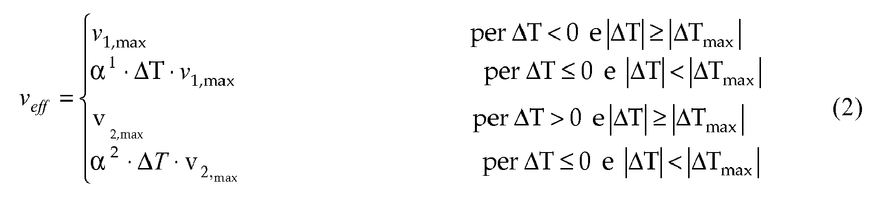
where α1 and a2 are two empirically calculated time constants, v 1,maX and v 2,max are two maximum speed values at which the fan is operated when the measured temperature is lower or higher than the reference temperature, respectively; these speed values depend on the ongoing cooking step and on which and/or how many heating elements are on. - Δ=T-Tref is the difference between the measured temperature and the reference temperature.
- Unlike the equation (1), in the equation (2) the actual speed is calculated according to a different law depending on whether the measured temperature is higher or lower than the reference temperature.
- In a further preferred and advantageous embodiment, the law that regulates the revolution speed of the fan 9 depends on at least two temperature values measured in the chamber; in particular, it depends both on the measured instantaneous temperature and on historical temperature values, i.e. values previously measured by the control unit.
- This optimises the response of the control system, and the fan revolution speed is changed less abruptly than in
Fig. 4 . - Such a type of control, which also takes into account historical temperature readings, may be attained through a PID (Proportional-Integral-Derivative) controller and a memory area (possibly internal to the PID controller) which stores the temperature values measured in the cooking chamber by the sensor 20 or a combination (e.g. a sum) of the values measured in the past.
- The values (whether punctual or combined) stored in this memory area represent the history of the cooking chamber temperatures and are used by the PID controller along with the measured instantaneous temperature in order to determine the actual speed at which the fan must be operated.
- In this case, therefore, the fan 9 is operated at an actual speed which is calculated according to the following law:

where v 1,maX and v 2,max are the two maximum speeds at which the fan 9 is operated; these speeds depend on the ongoing cooking step and on which and/or how many heating elements are on, ΔT is the difference between the temperature measured by the sensor 20 and the reference temperature, β1, β2 and β3 are constants obtained empirically and preferably dependent on the type of cooking program being carried out, tstart and tend are two time instants which delimit the time interval that defines the "history" to be taken into account, e.g. a time interval which ends at the instant when the actual speed is calculated and whose length equals the time elapsed between three or four updates of the fan revolution speed. - For example, referring to
Fig. 4 , if tend is equal to t5, then tstart may be t1 or t2 or the oven start-up time.
Claims (12)
- A method for heating a cooking chamber (5) of an oven (3), wherein
a heating element (7,8) heats said cooking chamber (5), and wherein
a fan (9) is operated at different speeds (v1,v2) in order to circulate hot air inside said cooking chamber (5),
the method being characterised in that said fan (9) is operated at a first speed (v1) when said heating element (7,8) is on, and said fan (9) is operated at a second speed (v2) when said heating element (7,8) is off. - A method according to any one of the preceding claims, wherein said oven comprises at least two heating elements (7,8), and wherein said heating element (8) is closer to said fan (9).
- A method according to claim 1 or 2, wherein at least one of said first speed (v1) and said second speed (v2) depends on the cooking step being carried out.
- A method according to claim 1 or 2 or 3, wherein said second speed (v1) is lower than said first speed (v2).
- A method according to claim 1 or 2 or 3 or 4, wherein at least one of said first speed (v1) and said second speed (v2) depends on the temperature measured inside the cooking chamber.
- A method according to claim 5, wherein at least one of said first speed (v1) and said second speed (v2) depends on the difference (ΔT) between a temperature measured inside the cooking chamber and a reference temperature (Tref).
- A method according to claim 6, wherein, when said temperature difference (ΔT) exceeds a reference value (ΔTmax), said fan is operated at a maximum speed (vmax) which depends on the on/off state of said heating element and on the cooking step being carried out.
- A method according to claim 7, wherein, when said temperature difference (ΔT) is smaller than a reference value (ΔTmax), said fan is operated at an actual speed (v1) that depends on said maximum speed (vmax) and on the difference (ΔT) between said measured temperature and a reference temperature (Tref).
- A method according to any one of the preceding claims, wherein at least one of said first speed and said second speed depends on at least two temperature values measured in the cooking chamber at different time instants.
- A method according to any one of the preceding claims, wherein said revolution speed depends on the humidity inside said cooking chamber.
- A method according to any one of the preceding claims, wherein a second fan (17) is turned on in order to circulate air within an interspace (13) between the muffle (4) of the oven (1) and an outer shell (14) of the oven, the method providing for controlling said second fan (17) depending on a temperature measured in the proximity of a control unit (20) of the oven (1), said control unit being installed within said interspace (13).
- An oven comprising
a cooking chamber (5) fitted with at least one heating element (7,8) for food cooking,
a fan (9) arranged in the proximity of said heating element and adapted to circulate air inside the cooking chamber (5),
an electronic control unit (12) adapted to control the operation of said fan and said at least one heating element,
and a temperature sensor (20) operationally connected to said control unit (12) and adapted to measure a temperature inside said cooking chamber (5),
characterised in that
said control unit (12) is adapted to implement the method according to any one of claims 1 to 11.
Applications Claiming Priority (1)
| Application Number | Priority Date | Filing Date | Title |
|---|---|---|---|
| IT000612A ITTO20090612A1 (en) | 2009-08-04 | 2009-08-04 | METHOD FOR HEATING A COOKING CHAMBER OF AN OVEN |
Publications (2)
| Publication Number | Publication Date |
|---|---|
| EP2282128A1 true EP2282128A1 (en) | 2011-02-09 |
| EP2282128B1 EP2282128B1 (en) | 2018-09-19 |
Family
ID=42174045
Family Applications (1)
| Application Number | Title | Priority Date | Filing Date |
|---|---|---|---|
| EP10171812.0A Active EP2282128B1 (en) | 2009-08-04 | 2010-08-03 | Method for heating a cooking chamber of an oven |
Country Status (2)
| Country | Link |
|---|---|
| EP (1) | EP2282128B1 (en) |
| IT (1) | ITTO20090612A1 (en) |
Cited By (9)
| Publication number | Priority date | Publication date | Assignee | Title |
|---|---|---|---|---|
| CN103296962A (en) * | 2012-02-29 | 2013-09-11 | 艾默生电气公司 | Speed control of variable-speed and multi-phase motor |
| WO2014044767A1 (en) * | 2012-09-21 | 2014-03-27 | E.G.O. Elektro-Gerätebau GmbH | Method for operating an oven, and oven |
| EP2896893A1 (en) | 2014-01-17 | 2015-07-22 | Electrolux Appliances Aktiebolag | Method of operating an air convection fan of a cooking oven and cooking oven |
| EP3018419A1 (en) * | 2014-11-07 | 2016-05-11 | Candy S.p.A. | Cooking oven |
| CN113180488A (en) * | 2021-01-28 | 2021-07-30 | 宁波方太厨具有限公司 | Air heater and oven for cooking device |
| WO2021188471A1 (en) * | 2020-03-19 | 2021-09-23 | Illinois Tool Works Inc. | Convection oven |
| EP4040049A1 (en) * | 2021-02-03 | 2022-08-10 | LG Electronics Inc. | Oven and method for controlling the same |
| CN116058676A (en) * | 2021-10-29 | 2023-05-05 | 浙江天喜厨电股份有限公司 | A control method for an air fryer |
| US20240353114A1 (en) * | 2023-04-18 | 2024-10-24 | Haier Us Appliance Solutions, Inc. | Cooking appliance including multiple heating zones |
Citations (8)
| Publication number | Priority date | Publication date | Assignee | Title |
|---|---|---|---|---|
| DE2657929A1 (en) * | 1976-12-21 | 1978-06-22 | Bosch Siemens Hausgeraete | Fan operated cooker oven with pyrolytic cleaner - has switch protecting fan motor by reducing speed or heating power |
| GB2172990A (en) | 1985-03-23 | 1986-10-01 | Buderus Ag | A method of cooking food in a forced circulation oven |
| EP1342414A1 (en) * | 2002-03-07 | 2003-09-10 | eloma GmbH Grossküchentechnik | Method for detecting the humidity in a device for treating and preparing food stuffs, and device for treating and preparing food stuffs |
| DE10303372A1 (en) * | 2003-01-29 | 2004-08-26 | Rational Ag | Roasting control method for controlling roasting of a joint or food product in an oven, whereby air flow in the oven is matched to cooking conditions |
| US20040262284A1 (en) * | 2001-10-22 | 2004-12-30 | Bsh Bosch Und Siemens Hausgerate Gmbh | Cooking device with high-speed heating unit |
| US20070246452A1 (en) * | 2006-04-20 | 2007-10-25 | Electrolux Home Products, Inc. | Variable speed convection in cooking applications |
| FR2900796A1 (en) * | 2006-05-15 | 2007-11-16 | Brandt Ind Sas | METHOD FOR COOKING A FOOD, AND IN PARTICULAR A FISH |
| EP1965137A1 (en) | 2007-03-01 | 2008-09-03 | CANDY S.p.A. | Method for treating food in a cooking oven, and a cooking oven |
Family Cites Families (1)
| Publication number | Priority date | Publication date | Assignee | Title |
|---|---|---|---|---|
| US4730100A (en) * | 1986-11-26 | 1988-03-08 | Jero Manufacturing, Inc. | Food cooking and heating apparatus |
-
2009
- 2009-08-04 IT IT000612A patent/ITTO20090612A1/en unknown
-
2010
- 2010-08-03 EP EP10171812.0A patent/EP2282128B1/en active Active
Patent Citations (8)
| Publication number | Priority date | Publication date | Assignee | Title |
|---|---|---|---|---|
| DE2657929A1 (en) * | 1976-12-21 | 1978-06-22 | Bosch Siemens Hausgeraete | Fan operated cooker oven with pyrolytic cleaner - has switch protecting fan motor by reducing speed or heating power |
| GB2172990A (en) | 1985-03-23 | 1986-10-01 | Buderus Ag | A method of cooking food in a forced circulation oven |
| US20040262284A1 (en) * | 2001-10-22 | 2004-12-30 | Bsh Bosch Und Siemens Hausgerate Gmbh | Cooking device with high-speed heating unit |
| EP1342414A1 (en) * | 2002-03-07 | 2003-09-10 | eloma GmbH Grossküchentechnik | Method for detecting the humidity in a device for treating and preparing food stuffs, and device for treating and preparing food stuffs |
| DE10303372A1 (en) * | 2003-01-29 | 2004-08-26 | Rational Ag | Roasting control method for controlling roasting of a joint or food product in an oven, whereby air flow in the oven is matched to cooking conditions |
| US20070246452A1 (en) * | 2006-04-20 | 2007-10-25 | Electrolux Home Products, Inc. | Variable speed convection in cooking applications |
| FR2900796A1 (en) * | 2006-05-15 | 2007-11-16 | Brandt Ind Sas | METHOD FOR COOKING A FOOD, AND IN PARTICULAR A FISH |
| EP1965137A1 (en) | 2007-03-01 | 2008-09-03 | CANDY S.p.A. | Method for treating food in a cooking oven, and a cooking oven |
Cited By (14)
| Publication number | Priority date | Publication date | Assignee | Title |
|---|---|---|---|---|
| US10084406B2 (en) | 2012-02-29 | 2018-09-25 | Emerson Electric Co. | Speed control of variable-speed multiple-phase motors |
| US9214890B2 (en) | 2012-02-29 | 2015-12-15 | Emerson Electric Co. | Speed control of variable-speed multiple-phase motors |
| CN103296962B (en) * | 2012-02-29 | 2017-08-15 | 艾默生电气公司 | The speed control of speed change multi-phase motor |
| CN103296962A (en) * | 2012-02-29 | 2013-09-11 | 艾默生电气公司 | Speed control of variable-speed and multi-phase motor |
| WO2014044767A1 (en) * | 2012-09-21 | 2014-03-27 | E.G.O. Elektro-Gerätebau GmbH | Method for operating an oven, and oven |
| EP2896893A1 (en) | 2014-01-17 | 2015-07-22 | Electrolux Appliances Aktiebolag | Method of operating an air convection fan of a cooking oven and cooking oven |
| EP3018419A1 (en) * | 2014-11-07 | 2016-05-11 | Candy S.p.A. | Cooking oven |
| WO2021188471A1 (en) * | 2020-03-19 | 2021-09-23 | Illinois Tool Works Inc. | Convection oven |
| CN113180488B (en) * | 2021-01-28 | 2022-10-21 | 宁波方太厨具有限公司 | Air heater and oven for cooking device |
| CN113180488A (en) * | 2021-01-28 | 2021-07-30 | 宁波方太厨具有限公司 | Air heater and oven for cooking device |
| EP4040049A1 (en) * | 2021-02-03 | 2022-08-10 | LG Electronics Inc. | Oven and method for controlling the same |
| US12152785B2 (en) | 2021-02-03 | 2024-11-26 | Lg Electronics Inc. | Oven and method for controlling the same |
| CN116058676A (en) * | 2021-10-29 | 2023-05-05 | 浙江天喜厨电股份有限公司 | A control method for an air fryer |
| US20240353114A1 (en) * | 2023-04-18 | 2024-10-24 | Haier Us Appliance Solutions, Inc. | Cooking appliance including multiple heating zones |
Also Published As
| Publication number | Publication date |
|---|---|
| ITTO20090612A1 (en) | 2011-02-05 |
| EP2282128B1 (en) | 2018-09-19 |
Similar Documents
| Publication | Publication Date | Title |
|---|---|---|
| EP2282128B1 (en) | Method for heating a cooking chamber of an oven | |
| EP2287533B1 (en) | Method for controlling the operation of an oven | |
| JP5531049B2 (en) | Oven with convection airflow and energy saving function | |
| EP3876798B1 (en) | Steam cooking apparatus | |
| US6943321B2 (en) | Convection oven with forced airflow circulation zones | |
| US6727478B2 (en) | Multi rack oven and methods for operating same | |
| JP4444312B2 (en) | Cooker | |
| EP2327934A1 (en) | Cooking device | |
| US20100193507A1 (en) | Speedcooking oven | |
| US20100012644A1 (en) | Dual fan convection performance divider | |
| EP3346188B1 (en) | Cooker | |
| US20240032720A1 (en) | Cooking apparatus | |
| US20260007136A1 (en) | Steam cooking method | |
| CN218635796U (en) | Steam cooking device | |
| JP2007303816A (en) | Cooker | |
| EP3748237B1 (en) | Apparatus for cooking food and method for generating steam | |
| JP4558543B2 (en) | Cooker | |
| JP3695658B2 (en) | Cooking device and control method thereof | |
| EP2327935A1 (en) | Cooking device with vapor producing device | |
| JP3587177B2 (en) | Cooking device | |
| JP2009284926A (en) | Cooking range | |
| CN118451281A (en) | Cooking appliance with an evaporator and method for operating the same | |
| JP2017072303A (en) | Cooker | |
| EP2354666A2 (en) | Self-cleaning method for an oven | |
| JP2005233493A (en) | High frequency cooking device |
Legal Events
| Date | Code | Title | Description |
|---|---|---|---|
| PUAI | Public reference made under article 153(3) epc to a published international application that has entered the european phase |
Free format text: ORIGINAL CODE: 0009012 |
|
| AK | Designated contracting states |
Kind code of ref document: A1 Designated state(s): AL AT BE BG CH CY CZ DE DK EE ES FI FR GB GR HR HU IE IS IT LI LT LU LV MC MK MT NL NO PL PT RO SE SI SK SM TR |
|
| AX | Request for extension of the european patent |
Extension state: BA ME RS |
|
| 17P | Request for examination filed |
Effective date: 20110609 |
|
| 17Q | First examination report despatched |
Effective date: 20140915 |
|
| STAA | Information on the status of an ep patent application or granted ep patent |
Free format text: STATUS: EXAMINATION IS IN PROGRESS |
|
| RAP1 | Party data changed (applicant data changed or rights of an application transferred) |
Owner name: WHIRLPOOL EMEA S.P.A |
|
| GRAP | Despatch of communication of intention to grant a patent |
Free format text: ORIGINAL CODE: EPIDOSNIGR1 |
|
| STAA | Information on the status of an ep patent application or granted ep patent |
Free format text: STATUS: GRANT OF PATENT IS INTENDED |
|
| INTG | Intention to grant announced |
Effective date: 20180327 |
|
| GRAS | Grant fee paid |
Free format text: ORIGINAL CODE: EPIDOSNIGR3 |
|
| GRAA | (expected) grant |
Free format text: ORIGINAL CODE: 0009210 |
|
| STAA | Information on the status of an ep patent application or granted ep patent |
Free format text: STATUS: THE PATENT HAS BEEN GRANTED |
|
| AK | Designated contracting states |
Kind code of ref document: B1 Designated state(s): AL AT BE BG CH CY CZ DE DK EE ES FI FR GB GR HR HU IE IS IT LI LT LU LV MC MK MT NL NO PL PT RO SE SI SK SM TR |
|
| REG | Reference to a national code |
Ref country code: GB Ref legal event code: FG4D |
|
| REG | Reference to a national code |
Ref country code: CH Ref legal event code: EP |
|
| REG | Reference to a national code |
Ref country code: DE Ref legal event code: R096 Ref document number: 602010053656 Country of ref document: DE |
|
| REG | Reference to a national code |
Ref country code: AT Ref legal event code: REF Ref document number: 1043675 Country of ref document: AT Kind code of ref document: T Effective date: 20181015 |
|
| REG | Reference to a national code |
Ref country code: IE Ref legal event code: FG4D |
|
| REG | Reference to a national code |
Ref country code: NL Ref legal event code: MP Effective date: 20180919 |
|
| PG25 | Lapsed in a contracting state [announced via postgrant information from national office to epo] |
Ref country code: SE Free format text: LAPSE BECAUSE OF FAILURE TO SUBMIT A TRANSLATION OF THE DESCRIPTION OR TO PAY THE FEE WITHIN THE PRESCRIBED TIME-LIMIT Effective date: 20180919 Ref country code: NO Free format text: LAPSE BECAUSE OF FAILURE TO SUBMIT A TRANSLATION OF THE DESCRIPTION OR TO PAY THE FEE WITHIN THE PRESCRIBED TIME-LIMIT Effective date: 20181219 Ref country code: FI Free format text: LAPSE BECAUSE OF FAILURE TO SUBMIT A TRANSLATION OF THE DESCRIPTION OR TO PAY THE FEE WITHIN THE PRESCRIBED TIME-LIMIT Effective date: 20180919 Ref country code: BG Free format text: LAPSE BECAUSE OF FAILURE TO SUBMIT A TRANSLATION OF THE DESCRIPTION OR TO PAY THE FEE WITHIN THE PRESCRIBED TIME-LIMIT Effective date: 20181219 Ref country code: LT Free format text: LAPSE BECAUSE OF FAILURE TO SUBMIT A TRANSLATION OF THE DESCRIPTION OR TO PAY THE FEE WITHIN THE PRESCRIBED TIME-LIMIT Effective date: 20180919 Ref country code: GR Free format text: LAPSE BECAUSE OF FAILURE TO SUBMIT A TRANSLATION OF THE DESCRIPTION OR TO PAY THE FEE WITHIN THE PRESCRIBED TIME-LIMIT Effective date: 20181220 |
|
| REG | Reference to a national code |
Ref country code: LT Ref legal event code: MG4D |
|
| PG25 | Lapsed in a contracting state [announced via postgrant information from national office to epo] |
Ref country code: AL Free format text: LAPSE BECAUSE OF FAILURE TO SUBMIT A TRANSLATION OF THE DESCRIPTION OR TO PAY THE FEE WITHIN THE PRESCRIBED TIME-LIMIT Effective date: 20180919 Ref country code: LV Free format text: LAPSE BECAUSE OF FAILURE TO SUBMIT A TRANSLATION OF THE DESCRIPTION OR TO PAY THE FEE WITHIN THE PRESCRIBED TIME-LIMIT Effective date: 20180919 Ref country code: HR Free format text: LAPSE BECAUSE OF FAILURE TO SUBMIT A TRANSLATION OF THE DESCRIPTION OR TO PAY THE FEE WITHIN THE PRESCRIBED TIME-LIMIT Effective date: 20180919 |
|
| REG | Reference to a national code |
Ref country code: AT Ref legal event code: MK05 Ref document number: 1043675 Country of ref document: AT Kind code of ref document: T Effective date: 20180919 |
|
| PG25 | Lapsed in a contracting state [announced via postgrant information from national office to epo] |
Ref country code: EE Free format text: LAPSE BECAUSE OF FAILURE TO SUBMIT A TRANSLATION OF THE DESCRIPTION OR TO PAY THE FEE WITHIN THE PRESCRIBED TIME-LIMIT Effective date: 20180919 Ref country code: NL Free format text: LAPSE BECAUSE OF FAILURE TO SUBMIT A TRANSLATION OF THE DESCRIPTION OR TO PAY THE FEE WITHIN THE PRESCRIBED TIME-LIMIT Effective date: 20180919 Ref country code: PL Free format text: LAPSE BECAUSE OF FAILURE TO SUBMIT A TRANSLATION OF THE DESCRIPTION OR TO PAY THE FEE WITHIN THE PRESCRIBED TIME-LIMIT Effective date: 20180919 Ref country code: IS Free format text: LAPSE BECAUSE OF FAILURE TO SUBMIT A TRANSLATION OF THE DESCRIPTION OR TO PAY THE FEE WITHIN THE PRESCRIBED TIME-LIMIT Effective date: 20190119 Ref country code: AT Free format text: LAPSE BECAUSE OF FAILURE TO SUBMIT A TRANSLATION OF THE DESCRIPTION OR TO PAY THE FEE WITHIN THE PRESCRIBED TIME-LIMIT Effective date: 20180919 Ref country code: ES Free format text: LAPSE BECAUSE OF FAILURE TO SUBMIT A TRANSLATION OF THE DESCRIPTION OR TO PAY THE FEE WITHIN THE PRESCRIBED TIME-LIMIT Effective date: 20180919 Ref country code: CZ Free format text: LAPSE BECAUSE OF FAILURE TO SUBMIT A TRANSLATION OF THE DESCRIPTION OR TO PAY THE FEE WITHIN THE PRESCRIBED TIME-LIMIT Effective date: 20180919 Ref country code: RO Free format text: LAPSE BECAUSE OF FAILURE TO SUBMIT A TRANSLATION OF THE DESCRIPTION OR TO PAY THE FEE WITHIN THE PRESCRIBED TIME-LIMIT Effective date: 20180919 |
|
| PG25 | Lapsed in a contracting state [announced via postgrant information from national office to epo] |
Ref country code: SK Free format text: LAPSE BECAUSE OF FAILURE TO SUBMIT A TRANSLATION OF THE DESCRIPTION OR TO PAY THE FEE WITHIN THE PRESCRIBED TIME-LIMIT Effective date: 20180919 Ref country code: SM Free format text: LAPSE BECAUSE OF FAILURE TO SUBMIT A TRANSLATION OF THE DESCRIPTION OR TO PAY THE FEE WITHIN THE PRESCRIBED TIME-LIMIT Effective date: 20180919 Ref country code: PT Free format text: LAPSE BECAUSE OF FAILURE TO SUBMIT A TRANSLATION OF THE DESCRIPTION OR TO PAY THE FEE WITHIN THE PRESCRIBED TIME-LIMIT Effective date: 20190119 |
|
| REG | Reference to a national code |
Ref country code: DE Ref legal event code: R097 Ref document number: 602010053656 Country of ref document: DE |
|
| PLBE | No opposition filed within time limit |
Free format text: ORIGINAL CODE: 0009261 |
|
| STAA | Information on the status of an ep patent application or granted ep patent |
Free format text: STATUS: NO OPPOSITION FILED WITHIN TIME LIMIT |
|
| PG25 | Lapsed in a contracting state [announced via postgrant information from national office to epo] |
Ref country code: DK Free format text: LAPSE BECAUSE OF FAILURE TO SUBMIT A TRANSLATION OF THE DESCRIPTION OR TO PAY THE FEE WITHIN THE PRESCRIBED TIME-LIMIT Effective date: 20180919 |
|
| 26N | No opposition filed |
Effective date: 20190620 |
|
| PG25 | Lapsed in a contracting state [announced via postgrant information from national office to epo] |
Ref country code: SI Free format text: LAPSE BECAUSE OF FAILURE TO SUBMIT A TRANSLATION OF THE DESCRIPTION OR TO PAY THE FEE WITHIN THE PRESCRIBED TIME-LIMIT Effective date: 20180919 |
|
| PG25 | Lapsed in a contracting state [announced via postgrant information from national office to epo] |
Ref country code: TR Free format text: LAPSE BECAUSE OF FAILURE TO SUBMIT A TRANSLATION OF THE DESCRIPTION OR TO PAY THE FEE WITHIN THE PRESCRIBED TIME-LIMIT Effective date: 20180919 |
|
| PG25 | Lapsed in a contracting state [announced via postgrant information from national office to epo] |
Ref country code: CH Free format text: LAPSE BECAUSE OF NON-PAYMENT OF DUE FEES Effective date: 20190831 Ref country code: MC Free format text: LAPSE BECAUSE OF FAILURE TO SUBMIT A TRANSLATION OF THE DESCRIPTION OR TO PAY THE FEE WITHIN THE PRESCRIBED TIME-LIMIT Effective date: 20180919 Ref country code: LU Free format text: LAPSE BECAUSE OF NON-PAYMENT OF DUE FEES Effective date: 20190803 Ref country code: LI Free format text: LAPSE BECAUSE OF NON-PAYMENT OF DUE FEES Effective date: 20190831 |
|
| REG | Reference to a national code |
Ref country code: BE Ref legal event code: MM Effective date: 20190831 |
|
| PG25 | Lapsed in a contracting state [announced via postgrant information from national office to epo] |
Ref country code: IE Free format text: LAPSE BECAUSE OF NON-PAYMENT OF DUE FEES Effective date: 20190803 |
|
| PG25 | Lapsed in a contracting state [announced via postgrant information from national office to epo] |
Ref country code: BE Free format text: LAPSE BECAUSE OF NON-PAYMENT OF DUE FEES Effective date: 20190831 |
|
| PG25 | Lapsed in a contracting state [announced via postgrant information from national office to epo] |
Ref country code: CY Free format text: LAPSE BECAUSE OF FAILURE TO SUBMIT A TRANSLATION OF THE DESCRIPTION OR TO PAY THE FEE WITHIN THE PRESCRIBED TIME-LIMIT Effective date: 20180919 |
|
| PG25 | Lapsed in a contracting state [announced via postgrant information from national office to epo] |
Ref country code: HU Free format text: LAPSE BECAUSE OF FAILURE TO SUBMIT A TRANSLATION OF THE DESCRIPTION OR TO PAY THE FEE WITHIN THE PRESCRIBED TIME-LIMIT; INVALID AB INITIO Effective date: 20100803 Ref country code: MT Free format text: LAPSE BECAUSE OF FAILURE TO SUBMIT A TRANSLATION OF THE DESCRIPTION OR TO PAY THE FEE WITHIN THE PRESCRIBED TIME-LIMIT Effective date: 20180919 |
|
| PG25 | Lapsed in a contracting state [announced via postgrant information from national office to epo] |
Ref country code: MK Free format text: LAPSE BECAUSE OF FAILURE TO SUBMIT A TRANSLATION OF THE DESCRIPTION OR TO PAY THE FEE WITHIN THE PRESCRIBED TIME-LIMIT Effective date: 20180919 |
|
| P01 | Opt-out of the competence of the unified patent court (upc) registered |
Effective date: 20230523 |
|
| REG | Reference to a national code |
Ref country code: DE Ref legal event code: R081 Ref document number: 602010053656 Country of ref document: DE Owner name: WHIRLPOOL EMEA S.R.L., IT Free format text: FORMER OWNER: WHIRLPOOL EMEA S.P.A, PERO, IT |
|
| PGFP | Annual fee paid to national office [announced via postgrant information from national office to epo] |
Ref country code: DE Payment date: 20240828 Year of fee payment: 15 |
|
| PGFP | Annual fee paid to national office [announced via postgrant information from national office to epo] |
Ref country code: GB Payment date: 20240827 Year of fee payment: 15 |
|
| PGFP | Annual fee paid to national office [announced via postgrant information from national office to epo] |
Ref country code: FR Payment date: 20240826 Year of fee payment: 15 |
|
| PGFP | Annual fee paid to national office [announced via postgrant information from national office to epo] |
Ref country code: IT Payment date: 20240722 Year of fee payment: 15 |
|
| REG | Reference to a national code |
Ref country code: DE Ref legal event code: R119 Ref document number: 602010053656 Country of ref document: DE |
|
| GBPC | Gb: european patent ceased through non-payment of renewal fee |
Effective date: 20250803 |