EP2282121A1 - Heat shield panels - Google Patents
Heat shield panels Download PDFInfo
- Publication number
- EP2282121A1 EP2282121A1 EP10012241A EP10012241A EP2282121A1 EP 2282121 A1 EP2282121 A1 EP 2282121A1 EP 10012241 A EP10012241 A EP 10012241A EP 10012241 A EP10012241 A EP 10012241A EP 2282121 A1 EP2282121 A1 EP 2282121A1
- Authority
- EP
- European Patent Office
- Prior art keywords
- heat shield
- cooling
- pins
- panel
- holes
- Prior art date
- Legal status (The legal status is an assumption and is not a legal conclusion. Google has not performed a legal analysis and makes no representation as to the accuracy of the status listed.)
- Granted
Links
Images


Classifications
-
- F—MECHANICAL ENGINEERING; LIGHTING; HEATING; WEAPONS; BLASTING
- F23—COMBUSTION APPARATUS; COMBUSTION PROCESSES
- F23R—GENERATING COMBUSTION PRODUCTS OF HIGH PRESSURE OR HIGH VELOCITY, e.g. GAS-TURBINE COMBUSTION CHAMBERS
- F23R3/00—Continuous combustion chambers using liquid or gaseous fuel
- F23R3/002—Wall structures
-
- F—MECHANICAL ENGINEERING; LIGHTING; HEATING; WEAPONS; BLASTING
- F23—COMBUSTION APPARATUS; COMBUSTION PROCESSES
- F23R—GENERATING COMBUSTION PRODUCTS OF HIGH PRESSURE OR HIGH VELOCITY, e.g. GAS-TURBINE COMBUSTION CHAMBERS
- F23R3/00—Continuous combustion chambers using liquid or gaseous fuel
- F23R3/02—Continuous combustion chambers using liquid or gaseous fuel characterised by the air-flow or gas-flow configuration
- F23R3/04—Air inlet arrangements
- F23R3/06—Arrangement of apertures along the flame tube
-
- F—MECHANICAL ENGINEERING; LIGHTING; HEATING; WEAPONS; BLASTING
- F23—COMBUSTION APPARATUS; COMBUSTION PROCESSES
- F23R—GENERATING COMBUSTION PRODUCTS OF HIGH PRESSURE OR HIGH VELOCITY, e.g. GAS-TURBINE COMBUSTION CHAMBERS
- F23R3/00—Continuous combustion chambers using liquid or gaseous fuel
- F23R3/42—Continuous combustion chambers using liquid or gaseous fuel characterised by the arrangement or form of the flame tubes or combustion chambers
- F23R3/60—Support structures; Attaching or mounting means
-
- F—MECHANICAL ENGINEERING; LIGHTING; HEATING; WEAPONS; BLASTING
- F23—COMBUSTION APPARATUS; COMBUSTION PROCESSES
- F23R—GENERATING COMBUSTION PRODUCTS OF HIGH PRESSURE OR HIGH VELOCITY, e.g. GAS-TURBINE COMBUSTION CHAMBERS
- F23R2900/00—Special features of, or arrangements for continuous combustion chambers; Combustion processes therefor
- F23R2900/03041—Effusion cooled combustion chamber walls or domes
-
- F—MECHANICAL ENGINEERING; LIGHTING; HEATING; WEAPONS; BLASTING
- F23—COMBUSTION APPARATUS; COMBUSTION PROCESSES
- F23R—GENERATING COMBUSTION PRODUCTS OF HIGH PRESSURE OR HIGH VELOCITY, e.g. GAS-TURBINE COMBUSTION CHAMBERS
- F23R2900/00—Special features of, or arrangements for continuous combustion chambers; Combustion processes therefor
- F23R2900/03042—Film cooled combustion chamber walls or domes
Definitions
- the present invention relates to combustors for gas turbine engines in general, and to heat shield panels for use in double wall gas turbine combustors in particular.
- Gas turbine engine combustors are generally subject to high thermal loads for prolonged periods of time. To alleviate the accompanying thermal stresses, it is known to cool the walls of the combustor. Cooling helps to increase the usable life of the combustor components and therefore increase the reliability of the overall engine.
- a combustor may include a plurality of overlapping wall segments successively arranged where the forward edge of each wall segment is positioned to catch cooling air passing by the outside of the combustor. The forward edge diverts cooling air over the internal side, or hot side, of the wall segment and thereby provides film cooling for the internal side of the segment.
- a disadvantage of this cooling arrangement is that the necessary hardware includes a multiplicity of parts. There is considerable value in minimizing the number of parts within a gas turbine engine, not only from a cost perspective, but also for safety and reliability reasons. Specifically, internal components such as turbines and compressors can be susceptible to damage from foreign objects carried within the air flow through the engine.
- a further disadvantage of the above described cooling arrangement is the overall weight which accompanies the multiplicity of parts. Weight is a critical design parameter of every component in a gas turbine engine, and that there is considerable advantage to minimizing weight wherever possible.
- twin wall configuration In other cooling arrangements, a twin wall configuration has been adopted where an inner wall and an outer wall are separated by a specific distance. Cooling air passes through holes in the outer wall and then again through holes in the inner wall, and finally into the combustion chamber.
- An advantage of a twin wall arrangement compared to an overlapping wall segment arrangement is that an assembled twin wall arrangement is structurally stronger.
- a disadvantage to the twin wall arrangement is that thermal growth must be accounted for closely. Specifically, the thermal load in a combustor tends to be non-uniform. As a result, different parts of the combustor will experience different amounts of thermal growth, stress and strain. If the thermal combustor design does not account for non-uniform thermal growth, stress, and strain, then the usable life of the combustor may be negatively affected.
- a heat shield panel or liner for use in a combustor for a gas turbine engine.
- the heat shield panel broadly comprises a hot side and a cold side and a plurality of cooling chambers on the cold side.
- Each cooling chamber has a plurality of film holes for allowing a coolant to flow from the cold side to the hot side.
- the cold side of each heat shield panel also has a front boundary wall, a rear boundary wall, and a plurality of inner rails extending between the front and rear boundary walls.
- a plurality of cooling chambers are formed by the front and rear boundary walls and the inner rails.
- the cold side also has a plurality of side walls.
- a plurality of the cooling chambers are formed by the front and rear boundary walls, the side walls, and the inner rails.
- the heat shield panels described herein are forward heat shield panels and rear heat shield panels.
- the front wall is formed by a forward wall segment.
- the front wall is formed by means for metering flow of cooling air over an edge of the panel.
- the metering means is preferably formed by a plurality of spaced apart pins.
- the rear boundary is formed by a rear wall.
- the rear boundary is formed by a means for metering flow of cooling over an edge of the panel.
- the metering means preferably comprises a plurality of pin arrays.
- the present invention also relates to a combustor for a gas turbine engine.
- the combustor broadly comprises an outer support shell and an inner support shell which together form a combustion chamber.
- the combustor further comprises an array of forward heat shield panels attached to the inner and outer support shells and an array of rear heat shield panels attached to the inner and outer support shells.
- the forward heat shield panels each have a plurality of dilution holes through which air passes into the combustion chamber.
- the rear heat shield panels each have a plurality of rails. Each rear heat shield panel is offset with respect to an adjacent one of the forward heat shield panels so that each rail is aligned with one of the dilution holes.
- a heat shield panel which has at least one chamber, a first set of cooling holes passing through the heat shield panel, and a second set of cooling holes passing through the heat shield panel.
- the first set of cooling holes has an orientation different from the second set of cooling holes.
- a heat shield panel which has means near an edge to meter flow of coolant air over that edge.
- the combustor 10 for a gas turbine engine comprises a radially outer support shell 12 and a radially inner support shell 14.
- the support shells 12 and 14 define an annular combustion chamber 16.
- the combustion chamber has a mean combustor airflow in the direction M.
- Heat shield panels or liners line the hot side of the inner and outer support shells 12 and 14.
- An array of forward heat shield panels 18 and an array of rear heat shield panels 20 line the hot side of the outer support shell 12, while an array of forward heat shield panels 22 and an array of rear heat shield panels 24 line the hot side of the inner support shell 14.
- Nuts 26 and bolts 28 may be used to connect each of the heat shield panels 18, 20, 22, and 24 to the respective inner and outer support shells 14 and 12.
- impingement cooling holes 30 penetrate through each of the inner and outer support shells 14 and 12 to allow a coolant, such as air, to enter the space between the inner and outer support shells 14 and 12 and the respective panels 18, 20, 22 and 24.
- Film cooling holes 32 penetrate each of the heat shield panels 18, 20, 22, and 24 to allow cooling air to pass from a cold side 31 of the panel to a hot side 33 of the panel and to promote the creation of a film of cooling air over the hot side 33 of each panel.
- FIG. 2A shows that a majority of the cooling air flow passing through the cooling holes 32 in the forward outer heat shield panels 18 has a first flow direction A, while a majority of the cooling air flow passing through the cooling holes 32 in the forward inner heat shield panels 22 has a second flow direction B, which flow direction is different from the first flow direction A.
- each of the forward panels 18 and 22, on its cold side 31, has circumferentially distributed major dilution holes 34 and minor dilution holes 36 near the panel's trailing edge 38.
- Raised rims 40 circumscribe each major dilution hole 34 and raised rims 42 circumscribe each minor dilution hole 36.
- the major dilution holes 34 and the minor dilution holes 36 of opposite panels radially oppose each other.
- Each of the forward heat shield panels 18 and 22 further have a peripheral boundary wall 43 formed by forward wall segment 44, side wall segments 46, and rear wall segment 48.
- the peripheral boundary wall 43 formed by these segments extends radially and contacts the support shell 12 or 14.
- Each of the forward heat shield panels 18 and 22 preferably subtends an arc of approximately 40 degrees.
- each of the forward heat shield panels 18 and 22 includes a plurality of inner rails or ribs 50 that extend axially from the forward peripheral wall segment 44 to the aft peripheral wall segment 48.
- the rails 50 are the same radial height as the peripheral walls segments 44, 46, and 48.
- the rails 50 define a plurality of circumferentially aligned, isolated cooling chambers 56 with the peripheral wall segments 44, 46, and 48.
- the rails 50 also provide structural support for the forward heat shield panels 18 and 22.
- cooling chambers 56 provide an even distribution of cooling air throughout the panels 18 and 22 by maintaining an optimum pressure drop through each panel section created by the axial inner rails 50 and the peripheral wall segments 44, 46, and 48. This pressure drop drives cooling air into every cooling film hole 32 in the respective heat shield panel 18 and 22 in each section in such a way that the respective heat shield panel 18 and 22 is optimally cooled by convection through the film holes 32 and by an even film flow.
- a breach e.g. a burn-through
- coolant can preferentially flow through this large area as it offers less resistance to the flow.
- the film holes away from this area will be starved of coolant and the cross-flow of air in the cavity that travels toward the large open area will decrease the effect of the impingement jets that it encounters in its trajectory. The combination of these two phenomena will cause an increase in metal temperature in the panel.
- any temperature increase will occur in a larger area of the heat shield panel causing the burn-through to expand to the entire heat shield panel. Under these circumstances, the release of a panel or a section of it, when attachment posts are lost, is unavoidable. There is a high risk of engine fire once a blade or vane in the turbine module is damaged due to rupture or burning.
- the forward heat shield panels 18 and 22 with their separate cooling chambers 56 avoid this problem.
- each forward heat shield panel 18 and 22 there are two particularly relevant regions in each forward heat shield panel 18 and 22 - the region 82 forward of the dilution holes 34 and the region 84 near the dilution holes 34.
- the cooling holes 32 in the forward region 82 have an orientation consistent with the local swirl direction of the combustion gases.
- the general direction of swirl in the vicinity of the front outer heat shield panels 18 is opposite the direction of swirl in the vicinity of the forward inner heat shield panels 22. Streams emanating from each fuel injector 86 and each fuel injector guide 88 establish the swirl direction.
- the film cooling holes 32 in the outer front heat shield panels 18 all have a positive circumferentially oblique orientation
- the film cooling holes 32 in the inner front heat shield panels 22 all have a negative circumferential oblique orientation. This can be seen in FIG. 2A .
- the film cooling holes 32 in any given panel 18 or 22 do not have the mix of positive and negative orientations on either side of the cooling chamber mean line, as is the case with the rear heat shield panels 20 and 24.
- the one exception to the cooling hole orientation described above for the heat shield panels 18 and 22 occurs in the vicinity of the axially extending rails 50 and the attachment posts 52. As shown in FIGS. 5 and 5A , the orientation of the cooling holes 32 on each side of each rail 50 is towards the respective rail 50. Further, cooling holes 32 in the vicinity of each attachment post 52 are oriented so that cooling air flows toward the attachment post 52. The cooling holes 32 are locally reversed so that film air is directed towards and over the rail 50 and the footprints of the posts 52. This is done to better cool the rail and post footprints.
- the concentration of film cooling holes 32, as well as the concentration of the impingement holes 30 shown in FIG. 2 is increased as compared to the region 82.
- the cooling holes 32 in the vicinity of each dilution hole 34 are oriented towards the respective dilution hole 34. This is done to increase the heat extraction on the panel in a region where the fuel spray cone from the injector 86, and its associated hot gases, have expanded in diameter and scrub the heat shield panels 18 and 22.
- the interaction of the fuel injector stream with the dilution jets generates high velocity and high turbulence flows and vortices around the dilution holes that diminish the effectiveness of the cooling film.
- the film cooling holes 32 are arranged in a fan like pattern. This deviation from the orientation of the film cooling holes 32 in the rest of the respective heat shield panel 18 or 22 allows for the direct injection of cooling film air over the footprint of the raised rims 40 and 42 of the respective dilution hole 34 or 36. If one were to keep the film hole orientation of the forward region of the heat shield panel, which is unidirectional, one-half of the raised rim footprint 40 or 42 of the dilution hole 34 or 36 would get no cooling film. Due to the high heat load on this region of the panel, as indicated above, an uncooled panel area is extremely undesirable.
- each of the rear heat shield panels 20 and 24, on its cold side, has a peripheral boundary wall formed by forward wall segment 58 and side wall segments 60.
- Each heat shield panel 20 and 24 also has a rear rail 62 extending from one side wall segment 60 to the opposite side wall segment 60 and a plurality of inner rails 64 extending between the forward wall segment 58 and the rear rail 62.
- Two attachment posts 66 are typically aligned with each inner rail 64 and two attachment posts 68 are located adjacent each of the side wall segments 60.
- the peripheral wall segments 58 and 60, the rear rail 62, and the inner rails 64 define a plurality of circumferentially aligned, isolated cooling chambers 70.
- each rear heat shield panel 20, 24 is arranged relative to a respective adjacent forward heat shield panel 18, 22 so that each of the inner rails 64 is circumferentially aligned with a major dilution hole 34. More fundamentally, the rails 64 are circumferentially offset from the major dilution holes 34 of the radially opposing liner panel and thus from the major dilution air jets admitted through the major dilution holes 34.
- each rail 64 and each attachment post 66 is inherently difficult to cool.
- the difficulty in cooling these footprints occurs for two reasons. First, one cannot effectively impinge cooling air on the rails 64 or posts 66 because they contact the support shell 12, 14 in order to define the isolated cooling chambers 70 as described above. Second, the rails 64 and posts 66 occupy enough circumferential distance that it is difficult to establish an effective cooling film over the footprints, even if one uses film holes positioned quite close to them and oriented so as to discharge their cooling film in the direction of the footprint.
- each of the rear heat shield panels 20, and 24, in the vicinity of each cooling chamber 70 has an axially extending zigzag line 72 which is located circumferentially midway between the inner rails 64 and/or the side wall segment 60 defining the side boundaries of a respective cooling chamber 70.
- the film cooling holes 32 on either side of each zigzag line 72 are obliquely oriented so that the cooling film issues from the film cooling holes 32 with a circumferential directional component toward the rail or wall segment footprint on the same side of the zigzag line 72.
- each zigzag line 72 has a positive orientation
- the holes 32 on the other side 76 of the zigzag line 72 have a negative orientation.
- the resultant circumferential directional component encourages the cooling film to flow over the rail and attachment post footprints, thus helping to cool the rails and the posts.
- the zigzag line 72 is defined such that the film hole orientation change varies circumferentially by a few degrees from row to row of cooling holes 32. By doing so, the area without any cooling film coverage is kept to a minimum.
- Wake or tornado-like vortices form downstream of a jet issuing transversely into a stream and such vortices originate in the boundary layer of the cross-flow after it separates from the wall from which the jet issues.
- the cooling film injected around and behind the dilution air jet is going to be part of these wake vortices and, therefore, be blown off the panel surface.
- An area where the film has blown off will show an increase in metal temperature due to the lack of protection from hot combustion gases that the film offers.
- the circumferential orientation of the film holes 32 in the rear heat shield panels 20 and 24 behind the dilution jet enforces or eliminates these wake vortices.
- Film holes circumferentially oblique with respect to the engine centerline result in high panel temperatures immediately downstream of the dilution jet with a patch of increased metal temperature further downstream.
- the fact that the patch follows the circumferential orientation of the film holes indicates that the wake vortices on either side of the jet, while pulling cooling film off the surface, has the same rotational direction as that of the film holes.
- film holes 32, such as those of the present invention, that behind the dilution jet are oriented circumferentially oblique directed toward the dilution symmetry plane 78, show no increase in metal temperature and no effect on the film effectiveness downstream of the dilution jet. Injecting film in opposing oblique orientation behind a transverse jet impedes the formation of wake vortices.
- each rear heat shield panel 20, 24 there is one localized region of each rear heat shield panel 20, 24 where the film cooling holes 32 are not obliquely oriented as described above.
- the holes 32 in the vicinity of the upstream peripheral wall segment 58 are oriented at 90 degrees so that the cooling film issues from these holes in the circumferential direction.
- the film holes are percussion drilled from the hot side of the panel rather than from the cold side of the panel. This is the preferred direction of drilling because it results in a trumpet shaped hole 32' as shown in FIG. 6 .
- the trumpet shaped hole 32' has a relatively small diameter on the cold side 31 of the panel 20, 24 and a relatively large diameter on the hot side 33 of the panel 20, 24.
- the 90 degree orientation also helps avoid structural damage to the panel during formation of the holes 32'.
- the 90 degree orientation allows for a relatively small axial distance between consecutive rows of holes and for the first row to be located extremely close to the peripheral rail wall segment 58. This, in turn, increases the heat extraction through convection in this critical region of the panels 20 and 24 where the film has not yet been established and where no impingement is possible on the rails.
- the oblique cooling film holes 32 may be limited to those holes that are circumferentially proximate the rails 64.
- the remaining cooling film holes 32 i.e. those closer to the mean line of the cooling chamber 70, are oriented at zero degrees, which is parallel to the mean combustor airflow direction M, or at ninety degrees, which is perpendicular to the mean combustor airflow direction M.
- the zero degree orientation may result in the lowest metal temperatures compared to the other orientations, i.e. universally oblique and the ninety degree.
- the universally oblique orientation however may be beneficial in the rear heat shield panel 20, 24 as compared to the zero and ninety degree orientation.
- the panel 18' has a boundary wall which includes side peripheral wall segments 46' and a rear or trailing edge peripheral wall segment 48'.
- the peripheral wall segment 48' extends radially and contacts the support shell 12 when properly positioned. This helps in directing the cooling air that impinges on the cold side of panel 18' to flow toward the panel cooling film holes 32' and exit through them.
- the contact of the wall segments 46' and 48' with the support shell 12 helps eliminate the presence of leakage passages through which air could exit the panel 18' bypassing the film holes 32'. If cooling air were to bypass the film holes 32', the panel metal temperature will undoubtedly increase.
- the panel 18' also has a plurality of inner rails 50' which divide the cold side of the panel 18' into a plurality of cooling chambers 56'.
- a plurality of attachment posts 52' are typically aligned with the inner rails 50'.
- a plurality of attachment posts 54' are positioned near the side peripheral wall segments 46'.
- the panel 18' has a plurality of major dilution holes 34', each surrounded by a raised rim 40', and a plurality of minor dilution holes 36' each surrounded by a raised rim 42'.
- Panel 18' differs from panel 18 in that the front peripheral wall segment 44 has been replaced by a means for metering the flow of air over the panel edge.
- These metering means preferably takes the form of an array of round pins 90.
- the round pins 90 are formed into a plurality of rows with the pins 90 in one row being offset from the pins 90 in an adjacent row.
- the pins 90 meter the cooling air leaving the panel 18'. This air is used to cool the leading edge 92 of the panel 18' as well as the outer and inner edges and lips of the bulkhead segment 94.
- the pins 90 may be spaced apart by any distance which achieves the desired cooling effect and a desired rate of cooling air flowing over the edge 92.
- the front row of pins 90 has been shown as being positioned near the leading edge 92, the front row of pins 90, if desired, could be recessed or spaced a distance away from the leading edge 92.
- the pins 90 have a height which allows the top of the pins to contact the support shell 12 when the panel 18' is properly positioned.
- One of the panels 18' attached to the support shell 12 may have one or more openings 96 for receiving an ignitor (not shown).
- FIG. 8 an alternative embodiment of a front heat shield panel 22' to be mounted to the inner support shell 14 is illustrated.
- the panel 22' has a boundary formed by side wall rail segments 46' and a rear peripheral wall 48', a plurality of major dilution holes 34', each surrounded by a raised rim 40', a plurality of minor dilution holes 36', each surrounded by a raised rim 42', inner rails 50', and a plurality of isolated cooling chambers 56'.
- Attachment posts 52' are typically aligned with the inner rails 50' and attachment posts 54' are positioned adjacent or next to the side wall segments 46'.
- the rear wall 48' helps guide the cooling air through the film cooling holes 32' and towards the leading edge 98 of the panel 22'.
- the panel 22' also has means for metering the flow of cooling air over the leading edge 98 of the panel.
- the metering means preferably comprises a plurality of rows of round pins 100, preferably two rows of such pins. As can be seen from FIG. 8 , the pins 100 in one row are offset with respect to the pins 100 in an adjacent row. As before, the pins 100 may be separated by any desired distance sufficient to achieve a desired cooling air flow rate over the leading edge 98 and onto the bulkhead segment 94. While the front row of pins 100 has been illustrated as being near the leading edge 98, the front row of pins 100 may be recessed or spaced away from the leading edge 98 if desired. The pins 100 have sufficient height that the top of the pins 100 contact the support shell 14 when the panel 22' is installed.
- the two mechanisms that provide heat extraction from the leading edge of the panels are convection from the pins on the cold side and protection from hot gases by the film layer created as the cooling air is channeled and directed toward the hot surface of the panel.
- the panels 18' and 22' are each provided with a cooling hole 32 configuration such as shown in and discussed with respect to FIG. 5 .
- the outer and inner support shells 12 and 14 are connected to the first row of stator vanes 102 in the engine turbine section.
- the stator vanes 102 cause bow waves which may cause damage to the combustor and shorten its service life.
- the panels 20' and 24' help avoid the problem of bow wave damage.
- each of the panels 20' and 24' have a boundary which is at least partially defined by a forward rail 58' and side rails 60'.
- the rails 58' and 60' contact the respective support shell 12 or 14 when the panel 20' and 24' is installed and thus help force cooling air through the film holes 32 and towards the trailing edge 106 of the respective panel 20' or 24'.
- the panels 20' and 24' also have a plurality of inner rails 64' which form a plurality of cooling chambers 70' on the cold side.
- a plurality of attachment posts 66' are typically aligned with each inner rail 64' and a plurality of attachment posts 68' are located adjacent or next to the side rails 60'.
- each of the panels 20' and 24' no longer have a rear rail 62. Instead, each of the panels 20' and 24 has a means for metering the flow of cooling air over the trailing edge 106 of the respective panel 20', 24'.
- the metering means includes an array 104 of round pins adjacent the trailing edge 106 of the respective panel 20' and 24'. The pins in each array 104 extend to the respective support shell 12 or 14 when the panel 20' and 24' is installed.
- the pin array 104 includes a plurality of first array sections 108. As can be seen from FIGS. 9 and 10 , each section 108 has a plurality of rows of pins 112 with adjacent rows of pins 112 being offset. Further, each section 108 is surrounded by a substantially rectangular rail 114. Each of the sections 108 is aligned with the leading edge 116 of the first turbine stator vane 102.
- a vortical flow structure is created on the leading edge 116.
- This vortex wraps around the suction and pressure side of the respective vane 102 along its entire span.
- this vortex interacts with the cold side cooling air and film from the rear heat shield panel 20' and 24' to generate a strong secondary flow system.
- the high pressure vortex which is generated obstructs the constant flow of cooling air from the cold side and brings hot gases from the mid-span region of the combustion chamber exit.
- the metering means includes a relatively tight pin array 118, which is translated into low cooling airflow.
- the pin array 118 is provided to keep this region below the design metal temperature while guaranteeing an adequate cooling flow through the panel film cooling holes 32.
- each pin array 118 includes a plurality of rows of offset pins 120 having a diameter larger than the diameter of the pins 112. Further, the spacing between adjacent pins 120 is less than the spacing between adjacent pins 112.
- a row of pins 122 having a diameter smaller than that of the pins 120 may be included as a sacrificial feature in case burning occurs since it would be undesirable to lose a row of pins 120 due to burning. Such a loss would considerably decrease the flow resistance in this region and hence starve the panel film holes 32 of needed cooling air.
- the pins 122 are preferably offset from the pins 120 in the adjacent row.
- pin arrays 108 and 118 have been shown to have an end row 124 and 126 respectively near the trailing edge 106 of the panel 20', 24', the end rows 124 and 126 may be spaced away or recessed from the trailing edge 106.
- the pin arrays on the panels 18' and 22' allow some of the paneling air to be used three times to transfer heat out of the panel as the coolant impinges on the panel at a 90 degree angle, to transfer heat out of the panel as it flows past the pins, and to prevent heat from getting into the panel by forming a film on the hot side of the panel.
- the pin arrays at the aft end of the panels 20' and 24' allow similar things, except that a film is formed on and protects the platform of the first turbine stator vane. Further, the area on the panels 20' and 24' that prevents the vane bow wave from damaging the combustor has a loose cooling pin array which is angled toward the vane. This allows the air to maintain a higher total pressure to counteract the bow wave.
- FIG. 11 another alternative embodiment of a rear heat shield panel 20", 24 “ is illustrated.
- the panel 20", 24 “ has side walls 160", forward wall 158", and a plurality of inner rails 164 " which define a plurality of chambers 170".
- the panel 20", 24" has a rear wall 172" which has a plurality of flow metering segments 174".
- the flow metering segments 174 " are formed by an array of offset pins 176" .
- Each panel 20" , 24” has an array of offset pins 180" near or recessed from a trailing edge 182" of the panel.
- the pins 180" also function as a means for metering the cooling air flow over the trailing edge 182" of the panel.
- the pins 180" may be arranged in rows of offset pins. The spacing between the pins 176" and 180" define the flow rate of cooling air over the trailing edge 182".
- the panels 20", 24 " also have a pair of attachment posts 166" typically aligned with each of the rails 164" and a pair of attachment posts 168" positioned near the sidewalls 160". While not shown in FIG. 11 , each panel 20", 24 “ has a first set of cooling holes with a first desired orientation, such as 90 degrees with respect to the mean combustor airflow direction M, and additional sets of cooling holes near the posts 168" and 166", the rails 164", and the walls 160", 158", and 164".
- the additional sets of cooling holes near the posts 166" and 168" are arranged in a fan pattern and are oriented towards the posts 166" and 168".
- the cooling holes near the walls 160" and 158" and the rails 164" are preferably oriented towards the walls 160" and 158" and the rails 164 " to provide cooling air to cool these features.
- FIG. 12 is an alternative heat embodiment of a rear heat shield panel 320 for use in a combustor of a gas turbine engine as either an outer rear heat shield panel or an inner heat shield panel.
- the panel 320 has a forward rail 322, side rails 324, inner rails 325, and a rear rail 326 forming a plurality of chambers 327.
- the cooling holes 32 in the region 328 are straight back holes, while the cooling holes 32 near where the side rails 324 meet the rails 322 and 326 are angled toward the rails. Further, the cooling holes in the vicinity of the inner rails 325 and the attachment posts 330 and 332 are angled towards the inner rails 325 and the attachment posts 330 and 332 respectively.
- the panel 320 further has a plurality of rows of pins 334 for metering the flow of cooling air over the panel edge 336. As before, the rows of pins 334 are offset. The diameter of the pins 334 and their spacing determine the flow rate of the cooling air. If desired, a rail 338 may be placed around the rows of pins 334.
- FIG. 13 illustrates another embodiment of a heat shield panel 320' which may be used for the inner and outer rear heat shield panels.
- the panel 320' is identical to the panel 320 except for the cooling holes 32 in the region 328 being oriented 90 degrees with respect to the mean combustor airflow direction M.
Abstract
Description
- The present invention relates to combustors for gas turbine engines in general, and to heat shield panels for use in double wall gas turbine combustors in particular.
- Gas turbine engine combustors are generally subject to high thermal loads for prolonged periods of time. To alleviate the accompanying thermal stresses, it is known to cool the walls of the combustor. Cooling helps to increase the usable life of the combustor components and therefore increase the reliability of the overall engine.
- In one cooling embodiment, a combustor may include a plurality of overlapping wall segments successively arranged where the forward edge of each wall segment is positioned to catch cooling air passing by the outside of the combustor. The forward edge diverts cooling air over the internal side, or hot side, of the wall segment and thereby provides film cooling for the internal side of the segment. A disadvantage of this cooling arrangement is that the necessary hardware includes a multiplicity of parts. There is considerable value in minimizing the number of parts within a gas turbine engine, not only from a cost perspective, but also for safety and reliability reasons. Specifically, internal components such as turbines and compressors can be susceptible to damage from foreign objects carried within the air flow through the engine.
- A further disadvantage of the above described cooling arrangement is the overall weight which accompanies the multiplicity of parts. Weight is a critical design parameter of every component in a gas turbine engine, and that there is considerable advantage to minimizing weight wherever possible.
- In other cooling arrangements, a twin wall configuration has been adopted where an inner wall and an outer wall are separated by a specific distance. Cooling air passes through holes in the outer wall and then again through holes in the inner wall, and finally into the combustion chamber. An advantage of a twin wall arrangement compared to an overlapping wall segment arrangement is that an assembled twin wall arrangement is structurally stronger. A disadvantage to the twin wall arrangement, however, is that thermal growth must be accounted for closely. Specifically, the thermal load in a combustor tends to be non-uniform. As a result, different parts of the combustor will experience different amounts of thermal growth, stress and strain. If the thermal combustor design does not account for non-uniform thermal growth, stress, and strain, then the usable life of the combustor may be negatively affected.
- In many combustors, there is also a problem with damage to the combustor caused by vane bow waves. Failure to counteract these vane bow waves also shortens the life of the combustor.
- Accordingly, it is an object of the present invention in its preferred embodiments at least to provide heat shield panels for a combustor of a gas turbine engine which provide effective cooling.
- It is a further object of the present invention in its preferred embodiments at least to provide an improved combustor which has an increased service life.
- In accordance with a first aspect of the present invention, a heat shield panel or liner for use in a combustor for a gas turbine engine is provided. The heat shield panel broadly comprises a hot side and a cold side and a plurality of cooling chambers on the cold side. Each cooling chamber has a plurality of film holes for allowing a coolant to flow from the cold side to the hot side.
- In a described embodiment, the cold side of each heat shield panel also has a front boundary wall, a rear boundary wall, and a plurality of inner rails extending between the front and rear boundary walls. A plurality of cooling chambers are formed by the front and rear boundary walls and the inner rails. The cold side also has a plurality of side walls. A plurality of the cooling chambers are formed by the front and rear boundary walls, the side walls, and the inner rails.
- The heat shield panels described herein are forward heat shield panels and rear heat shield panels. In a first embodiment of a forward heat shield panel, the front wall is formed by a forward wall segment. In a second embodiment of a forward heat shield panel, the front wall is formed by means for metering flow of cooling air over an edge of the panel. The metering means is preferably formed by a plurality of spaced apart pins. In a first embodiment of a rear heat shield panel, the rear boundary is formed by a rear wall. In a second embodiment of a rear heat shield panel, the rear boundary is formed by a means for metering flow of cooling over an edge of the panel. The metering means preferably comprises a plurality of pin arrays.
- The present invention also relates to a combustor for a gas turbine engine. The combustor broadly comprises an outer support shell and an inner support shell which together form a combustion chamber. The combustor further comprises an array of forward heat shield panels attached to the inner and outer support shells and an array of rear heat shield panels attached to the inner and outer support shells. The forward heat shield panels each have a plurality of dilution holes through which air passes into the combustion chamber. The rear heat shield panels each have a plurality of rails. Each rear heat shield panel is offset with respect to an adjacent one of the forward heat shield panels so that each rail is aligned with one of the dilution holes.
- In yet another aspect of the present invention, a heat shield panel is provided which has at least one chamber, a first set of cooling holes passing through the heat shield panel, and a second set of cooling holes passing through the heat shield panel. The first set of cooling holes has an orientation different from the second set of cooling holes.
- In a yet further aspect of the invention, a heat shield panel is provided which has means near an edge to meter flow of coolant air over that edge.
- Other details of the gas turbine combustor of the present invention, as well as other advantages attendant thereto, are set forth in the following detailed description and the accompanying drawings wherein like reference numerals depict like elements.
-
-
FIG. 1 is a sectional view of a combustor for a gas turbine engine; -
FIG. 2 is a partial view of a shell and a heat shield panel liner in the combustor ofFIG. 1 ; -
FIG. 2A is a sectional view of the combustor taken alonglines 2A - 2A inFIG. 1 ; -
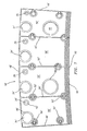
FIG. 3 is a top view of a cold side of each of the forward heat shield panels used in the combustor ofFIG. 1 ; -
FIG. 4 is a view of the cold side of a rear heat shield panel; -
FIG. 5 is a view showing the arrangement of adjoining forward and rear heat shield panels in a combustor; -
FIG. 5A is an enlarged view of a portion of a forward heat shield panel; -
FIG. 5B is an enlarged view of a portion of a rear heat shield panel; -
FIG. 5C is a schematic representation of the alignment of the forward heat shield panels with the rear heat shield panels; -
FIG. 6 is a sectional view showing a cooling film hole used in the heat shield panels of the present invention; -
FIG. 7 is a view of an alternative embodiment of an outer forward heat shield panel; -
FIG. 8 is a view of an alternative embodiment of an inner forward heat shield panel; -
FIG. 9 is a view of an alternative embodiment of an outer rear heat shield panel; -
FIG. 10 is a view of an alternative embodiment of an inner rear heat shield panel; -
FIG. 11 is a view of yet another alternative embodiment of a forward heat shield panel; -
FIG. 12 is a view of another alternative embodiment of a rear heat shield panel; and -
FIG. 13 is a view of another alternative embodiment of a rear heat shield panel. - Referring now to
FIG. 1 , thecombustor 10 for a gas turbine engine comprises a radiallyouter support shell 12 and a radiallyinner support shell 14. Thesupport shells annular combustion chamber 16. The combustion chamber has a mean combustor airflow in the direction M. - Heat shield panels or liners line the hot side of the inner and
outer support shells heat shield panels 18 and an array of rearheat shield panels 20 line the hot side of theouter support shell 12, while an array of forwardheat shield panels 22 and an array of rearheat shield panels 24 line the hot side of theinner support shell 14.Nuts 26 andbolts 28 may be used to connect each of theheat shield panels outer support shells - As shown in
FIG. 2 , impingement cooling holes 30 penetrate through each of the inner andouter support shells outer support shells respective panels heat shield panels cold side 31 of the panel to ahot side 33 of the panel and to promote the creation of a film of cooling air over thehot side 33 of each panel.FIG. 2A shows that a majority of the cooling air flow passing through the cooling holes 32 in the forward outerheat shield panels 18 has a first flow direction A, while a majority of the cooling air flow passing through the cooling holes 32 in the forward innerheat shield panels 22 has a second flow direction B, which flow direction is different from the first flow direction A. - Referring now to
FIG. 3 , each of theforward panels cold side 31, has circumferentially distributed major dilution holes 34 and minor dilution holes 36 near the panel's trailingedge 38. Raised rims 40 circumscribe eachmajor dilution hole 34 and raisedrims 42 circumscribe eachminor dilution hole 36. In a fully assembled combustor, the major dilution holes 34 and the minor dilution holes 36 of opposite panels radially oppose each other. - Each of the forward
heat shield panels peripheral boundary wall 43 formed byforward wall segment 44,side wall segments 46, andrear wall segment 48. Theperipheral boundary wall 43 formed by these segments extends radially and contacts thesupport shell heat shield panels - As can be seen from
FIG. 3 , each of the forwardheat shield panels ribs 50 that extend axially from the forwardperipheral wall segment 44 to the aftperipheral wall segment 48. There are twoattachment posts 52 typically aligned with eachrail 50 and two additional attachment posts 54 positioned next to each sideperipheral wall segment 46. Therails 50 are the same radial height as theperipheral walls segments rails 50 define a plurality of circumferentially aligned, isolated coolingchambers 56 with theperipheral wall segments rails 50 also provide structural support for the forwardheat shield panels - The creation of
separate cooling chambers 56 is advantageous in that the coolingchambers 56 provide an even distribution of cooling air throughout thepanels inner rails 50 and theperipheral wall segments cooling film hole 32 in the respectiveheat shield panel heat shield panel - If a heat shield panel were to have a region with a large open area compared to the rest of the panel, a breach, e.g. a burn-through, can cause coolant to preferentially flow through this large area as it offers less resistance to the flow. In such a case, the film holes away from this area will be starved of coolant and the cross-flow of air in the cavity that travels toward the large open area will decrease the effect of the impingement jets that it encounters in its trajectory. The combination of these two phenomena will cause an increase in metal temperature in the panel. These problems are avoided by the forward
heat shield panels chambers 56. If a major breach occurs in one of theheat shield panels chamber 56 where the breach is located, leaving theother cooling chambers 56 operating at the design temperature and the entire heat shield panel safety in place. As one can see from the foregoing discussion, if a forward heat shield panel is not equipped with separate orisolated cooling chambers 56 as in the present invention, any temperature increase will occur in a larger area of the heat shield panel causing the burn-through to expand to the entire heat shield panel. Under these circumstances, the release of a panel or a section of it, when attachment posts are lost, is unavoidable. There is a high risk of engine fire once a blade or vane in the turbine module is damaged due to rupture or burning. The forwardheat shield panels separate cooling chambers 56 avoid this problem. - Referring now to
FIG. 5 , there are two particularly relevant regions in each forwardheat shield panel 18 and 22 - theregion 82 forward of the dilution holes 34 and theregion 84 near the dilution holes 34. The cooling holes 32 in theforward region 82, as shown inFIG. 2A , have an orientation consistent with the local swirl direction of the combustion gases. The general direction of swirl in the vicinity of the front outerheat shield panels 18 is opposite the direction of swirl in the vicinity of the forward innerheat shield panels 22. Streams emanating from eachfuel injector 86 and eachfuel injector guide 88 establish the swirl direction. Accordingly, and except as noted in the next paragraph, the film cooling holes 32 in the outer frontheat shield panels 18 all have a positive circumferentially oblique orientation, whereas the film cooling holes 32 in the inner frontheat shield panels 22 all have a negative circumferential oblique orientation. This can be seen inFIG. 2A . The film cooling holes 32 in any givenpanel heat shield panels - The one exception to the cooling hole orientation described above for the
heat shield panels axially extending rails 50 and the attachment posts 52. As shown inFIGS. 5 and5A , the orientation of the cooling holes 32 on each side of eachrail 50 is towards therespective rail 50. Further, cooling holes 32 in the vicinity of each attachment post 52 are oriented so that cooling air flows toward theattachment post 52. The cooling holes 32 are locally reversed so that film air is directed towards and over therail 50 and the footprints of theposts 52. This is done to better cool the rail and post footprints. - As shown in
FIGS. 5 and5A , in the vicinity of the dilution holes 34, the concentration of film cooling holes 32, as well as the concentration of the impingement holes 30 shown inFIG. 2 , is increased as compared to theregion 82. Further, the cooling holes 32 in the vicinity of eachdilution hole 34 are oriented towards therespective dilution hole 34. This is done to increase the heat extraction on the panel in a region where the fuel spray cone from theinjector 86, and its associated hot gases, have expanded in diameter and scrub theheat shield panels FIG. 5A , in the vicinity of the dilution holes 34, the film cooling holes 32 are arranged in a fan like pattern. This deviation from the orientation of the film cooling holes 32 in the rest of the respectiveheat shield panel rims respective dilution hole rim footprint dilution hole - Referring now to
FIG. 4 , each of the rearheat shield panels forward wall segment 58 andside wall segments 60. Eachheat shield panel rear rail 62 extending from oneside wall segment 60 to the oppositeside wall segment 60 and a plurality ofinner rails 64 extending between theforward wall segment 58 and therear rail 62. Two attachment posts 66 are typically aligned with eachinner rail 64 and twoattachment posts 68 are located adjacent each of theside wall segments 60. As in the forward heat shield panels, theperipheral wall segments rear rail 62, and theinner rails 64 define a plurality of circumferentially aligned, isolated coolingchambers 70. - As can be seen in
FIGS. 5 and5C , each rearheat shield panel heat shield panel inner rails 64 is circumferentially aligned with amajor dilution hole 34. More fundamentally, therails 64 are circumferentially offset from the major dilution holes 34 of the radially opposing liner panel and thus from the major dilution air jets admitted through the major dilution holes 34. - The advantage of the arrangement shown in
FIG. 5 arises from the fact that the footprint of eachrail 64 and each attachment post 66 is inherently difficult to cool. The difficulty in cooling these footprints occurs for two reasons. First, one cannot effectively impinge cooling air on therails 64 orposts 66 because they contact thesupport shell isolated cooling chambers 70 as described above. Second, therails 64 andposts 66 occupy enough circumferential distance that it is difficult to establish an effective cooling film over the footprints, even if one uses film holes positioned quite close to them and oriented so as to discharge their cooling film in the direction of the footprint. This inability to effectively cool the footprints would be exacerbated if the footprints were to be circumferentially aligned with amajor dilution hole 34 of the radially opposed heat shield panel. This is because the major dilution jets penetrate across the annulus and scrub the radially opposing heat shield panel. This scrubbing effect can diminish the cooling effectiveness of the cooling film on the radially opposing heat shield panel or might even scrub the cooling film off the radially opposing liner, thus directly exposing the heat shield panel to the hot stoichiometric shear layer of the dilution jet. By contrast, the minor dilution jets issuing from the minor dilution holes 36 do not penetrate completely across the annulus. Therefore, it is advantageous to circumferentially align the rail footprint, and hence the attachment posts 66, with a radially opposingminor dilution hole 36, or at least not to align the footprint with amajor dilution hole 34. - As shown in
FIGS. 5 and5B , each of the rearheat shield panels chamber 70, has an axially extendingzigzag line 72 which is located circumferentially midway between theinner rails 64 and/or theside wall segment 60 defining the side boundaries of arespective cooling chamber 70. The film cooling holes 32 on either side of eachzigzag line 72 are obliquely oriented so that the cooling film issues from the film cooling holes 32 with a circumferential directional component toward the rail or wall segment footprint on the same side of thezigzag line 72. Thus, theholes 32 on oneside 74 of eachzigzag line 72 have a positive orientation, whereas theholes 32 on theother side 76 of thezigzag line 72 have a negative orientation. The resultant circumferential directional component encourages the cooling film to flow over the rail and attachment post footprints, thus helping to cool the rails and the posts. Thezigzag line 72 is defined such that the film hole orientation change varies circumferentially by a few degrees from row to row of cooling holes 32. By doing so, the area without any cooling film coverage is kept to a minimum. If one were to define the film hole orientation change at the same circumferential location on every row of film holes 32, for example at the mean line of each coolingchamber 70, there would be a well defined axial stretch of panel with no cooling film coverage. This has been proven to increase the metal temperature in this area above the level required for a full-life combustor. Another advantage to the positive and negative orientations of the film cooling holes 32 in theheat shield panels combustion chamber 16 immediately forward of the rearheat shield panels heat shield panels - There is one localized region of each rear
heat shield panel holes 32 in the vicinity of the upstreamperipheral wall segment 58 are oriented at 90 degrees so that the cooling film issues from these holes in the circumferential direction. There are two reasons for this. First, the film holes are percussion drilled from the hot side of the panel rather than from the cold side of the panel. This is the preferred direction of drilling because it results in a trumpet shaped hole 32' as shown inFIG. 6 . The trumpet shaped hole 32' has a relatively small diameter on thecold side 31 of thepanel hot side 33 of thepanel hot side 33 helps to diffuse the cooling film and encourage the film to adhere and spread on the hot side surface rather than penetrate into thecombustion chamber 16. The 90 degree orientation also helps avoid structural damage to the panel during formation of the holes 32'. Second, the 90 degree orientation allows for a relatively small axial distance between consecutive rows of holes and for the first row to be located extremely close to the peripheralrail wall segment 58. This, in turn, increases the heat extraction through convection in this critical region of thepanels - In an alternative embodiment of the
panels rails 64. In this hybrid embodiment, the remaining cooling film holes 32, i.e. those closer to the mean line of the coolingchamber 70, are oriented at zero degrees, which is parallel to the mean combustor airflow direction M, or at ninety degrees, which is perpendicular to the mean combustor airflow direction M. The selection of either one of these embodiments, including the universally oblique orientation described above, strongly depends on the local and mean velocities and turbulence level of the external combustor flow, the impingement and film hole densities, i.e. axial and circumferential spacing between consecutive holes, and the panel geometry. On a rearheat shield panel heat shield panel - Referring now to
FIGS. 7 and8 , alternative embodiments of the forward heat shield panels 18' and 22' are illustrated. As can be seen fromFIG. 7 , the panel 18' has a boundary wall which includes side peripheral wall segments 46' and a rear or trailing edge peripheral wall segment 48'. The peripheral wall segment 48' extends radially and contacts thesupport shell 12 when properly positioned. This helps in directing the cooling air that impinges on the cold side of panel 18' to flow toward the panel cooling film holes 32' and exit through them. The contact of the wall segments 46' and 48' with thesupport shell 12 helps eliminate the presence of leakage passages through which air could exit the panel 18' bypassing the film holes 32'. If cooling air were to bypass the film holes 32', the panel metal temperature will undoubtedly increase. This increase would be due to the lack of heat extraction through the panel holes and the lack of protection from a film created by air exiting the panel holes 32' and hugging the hot surface of the panel 18'. Additionally, cooling air that is allowed to bypass the panel film holes 32' will not remain close to the panel surface but rather, will tend to freely flow towards the center of thechamber 16. It will burn in the fuel rich mixture of the rich burn zone and therefore increase the local gas temperature scrubbing the panel 18' as well as increase the production of pollutants. - As shown in
FIG. 7 , the panel 18' also has a plurality of inner rails 50' which divide the cold side of the panel 18' into a plurality of cooling chambers 56'. A plurality of attachment posts 52' are typically aligned with the inner rails 50'. Also, a plurality of attachment posts 54' are positioned near the side peripheral wall segments 46'. As before, the panel 18' has a plurality of major dilution holes 34', each surrounded by a raised rim 40', and a plurality of minor dilution holes 36' each surrounded by a raised rim 42'. - Panel 18' differs from
panel 18 in that the frontperipheral wall segment 44 has been replaced by a means for metering the flow of air over the panel edge. These metering means preferably takes the form of an array of round pins 90. As can be seen fromFIG. 7 , the round pins 90 are formed into a plurality of rows with thepins 90 in one row being offset from thepins 90 in an adjacent row. Thepins 90 meter the cooling air leaving the panel 18'. This air is used to cool theleading edge 92 of the panel 18' as well as the outer and inner edges and lips of thebulkhead segment 94. Thepins 90 may be spaced apart by any distance which achieves the desired cooling effect and a desired rate of cooling air flowing over theedge 92. While the front row ofpins 90 has been shown as being positioned near the leadingedge 92, the front row ofpins 90, if desired, could be recessed or spaced a distance away from the leadingedge 92. Thepins 90 have a height which allows the top of the pins to contact thesupport shell 12 when the panel 18' is properly positioned. - One of the panels 18' attached to the
support shell 12 may have one ormore openings 96 for receiving an ignitor (not shown). - Referring now to
FIG. 8 , an alternative embodiment of a front heat shield panel 22' to be mounted to theinner support shell 14 is illustrated. As before, the panel 22' has a boundary formed by side wall rail segments 46' and a rear peripheral wall 48', a plurality of major dilution holes 34', each surrounded by a raised rim 40', a plurality of minor dilution holes 36', each surrounded by a raised rim 42', inner rails 50', and a plurality of isolated cooling chambers 56'. Attachment posts 52' are typically aligned with the inner rails 50' and attachment posts 54' are positioned adjacent or next to the side wall segments 46'. The rear wall 48' helps guide the cooling air through the film cooling holes 32' and towards the leading edge 98 of the panel 22'. - In lieu of a front
peripheral wall 44, the panel 22' also has means for metering the flow of cooling air over the leading edge 98 of the panel. The metering means preferably comprises a plurality of rows ofround pins 100, preferably two rows of such pins. As can be seen fromFIG. 8 , thepins 100 in one row are offset with respect to thepins 100 in an adjacent row. As before, thepins 100 may be separated by any desired distance sufficient to achieve a desired cooling air flow rate over the leading edge 98 and onto thebulkhead segment 94. While the front row ofpins 100 has been illustrated as being near the leading edge 98, the front row ofpins 100 may be recessed or spaced away from the leading edge 98 if desired. Thepins 100 have sufficient height that the top of thepins 100 contact thesupport shell 14 when the panel 22' is installed. - In both panel 18' and panel 22', the two mechanisms that provide heat extraction from the leading edge of the panels are convection from the pins on the cold side and protection from hot gases by the film layer created as the cooling air is channeled and directed toward the hot surface of the panel. While not shown in
FIGS. 7 and8 , the panels 18' and 22' are each provided with acooling hole 32 configuration such as shown in and discussed with respect toFIG. 5 . - As shown in
FIG. 1 , the outer andinner support shells stator vanes 102 in the engine turbine section. The stator vanes 102 cause bow waves which may cause damage to the combustor and shorten its service life. The panels 20' and 24' help avoid the problem of bow wave damage. - Referring now to
FIGS. 9 and10 , each of the panels 20' and 24' have a boundary which is at least partially defined by a forward rail 58' and side rails 60'. The rails 58' and 60' contact therespective support shell edge 106 of the respective panel 20' or 24'. The panels 20' and 24' also have a plurality of inner rails 64' which form a plurality of cooling chambers 70' on the cold side. A plurality of attachment posts 66' are typically aligned with each inner rail 64' and a plurality of attachment posts 68' are located adjacent or next to the side rails 60'. - Each of the panels 20' and 24' no longer have a
rear rail 62. Instead, each of thepanels 20' and 24 has a means for metering the flow of cooling air over the trailingedge 106 of the respective panel 20', 24'. The metering means includes anarray 104 of round pins adjacent the trailingedge 106 of the respective panel 20' and 24'. The pins in eacharray 104 extend to therespective support shell - The
pin array 104 includes a plurality offirst array sections 108. As can be seen fromFIGS. 9 and10 , eachsection 108 has a plurality of rows ofpins 112 with adjacent rows ofpins 112 being offset. Further, eachsection 108 is surrounded by a substantiallyrectangular rail 114. Each of thesections 108 is aligned with theleading edge 116 of the firstturbine stator vane 102. - The distinct cavity created by the
rail 114 and by the loose array ofpins 112 secures a supply of cooling air to the vane platform (not shown) and to thepanel trailing edge 106. As a result of the flow over eachturbine vane 102, a vortical flow structure is created on theleading edge 116. This vortex wraps around the suction and pressure side of therespective vane 102 along its entire span. At the vane platform, this vortex interacts with the cold side cooling air and film from the rear heat shield panel 20' and 24' to generate a strong secondary flow system. The high pressure vortex which is generated obstructs the constant flow of cooling air from the cold side and brings hot gases from the mid-span region of the combustion chamber exit. Due to the above-mentioned flow behavior, an increase in the mass flow of cooling air directed at thevane leading edge 116 is needed to wash away the vortical structure and clear the region of hot gases. This increase is achieved locally by separating the flows on the trailingedge 106 of the panel with therail 114. - In regions circumferentially offset from the
vanes 102, the metering means includes a relativelytight pin array 118, which is translated into low cooling airflow. Thepin array 118 is provided to keep this region below the design metal temperature while guaranteeing an adequate cooling flow through the panel film cooling holes 32. As can be seen fromFIGS. 9 and10 , eachpin array 118 includes a plurality of rows of offsetpins 120 having a diameter larger than the diameter of thepins 112. Further, the spacing betweenadjacent pins 120 is less than the spacing betweenadjacent pins 112. If desired, a row ofpins 122 having a diameter smaller than that of thepins 120 may be included as a sacrificial feature in case burning occurs since it would be undesirable to lose a row ofpins 120 due to burning. Such a loss would considerably decrease the flow resistance in this region and hence starve the panel film holes 32 of needed cooling air. Thepins 122 are preferably offset from thepins 120 in the adjacent row. - Furthermore, while the
pin arrays end row edge 106 of the panel 20', 24', theend rows edge 106. - The pin arrays on the panels 18' and 22' allow some of the paneling air to be used three times to transfer heat out of the panel as the coolant impinges on the panel at a 90 degree angle, to transfer heat out of the panel as it flows past the pins, and to prevent heat from getting into the panel by forming a film on the hot side of the panel. The pin arrays at the aft end of the panels 20' and 24' allow similar things, except that a film is formed on and protects the platform of the first turbine stator vane. Further, the area on the panels 20' and 24' that prevents the vane bow wave from damaging the combustor has a loose cooling pin array which is angled toward the vane. This allows the air to maintain a higher total pressure to counteract the bow wave.
- Referring now to
FIG. 11 , another alternative embodiment of a rearheat shield panel 20", 24 " is illustrated. In this embodiment, thepanel 20", 24 " hasside walls 160",forward wall 158", and a plurality ofinner rails 164 " which define a plurality ofchambers 170". Thepanel 20", 24" has arear wall 172" which has a plurality offlow metering segments 174". Theflow metering segments 174 " are formed by an array of offsetpins 176" . Eachpanel 20" , 24" has an array of offsetpins 180" near or recessed from a trailingedge 182" of the panel. Thepins 180" also function as a means for metering the cooling air flow over the trailingedge 182" of the panel. Thepins 180" may be arranged in rows of offset pins. The spacing between thepins 176" and 180" define the flow rate of cooling air over the trailingedge 182". Thepanels 20", 24 " also have a pair of attachment posts 166" typically aligned with each of therails 164" and a pair of attachment posts 168" positioned near thesidewalls 160". While not shown inFIG. 11 , eachpanel 20", 24 " has a first set of cooling holes with a first desired orientation, such as 90 degrees with respect to the mean combustor airflow direction M, and additional sets of cooling holes near theposts 168" and 166", therails 164", and thewalls 160", 158", and 164". The additional sets of cooling holes near theposts 166" and 168" are arranged in a fan pattern and are oriented towards theposts 166" and 168". The cooling holes near thewalls 160" and 158" and therails 164" are preferably oriented towards thewalls 160" and 158" and therails 164 " to provide cooling air to cool these features. -
FIG. 12 is an alternative heat embodiment of a rearheat shield panel 320 for use in a combustor of a gas turbine engine as either an outer rear heat shield panel or an inner heat shield panel. Thepanel 320 has aforward rail 322, side rails 324,inner rails 325, and a rear rail 326 forming a plurality of chambers 327. The cooling holes 32 in the region 328 are straight back holes, while the cooling holes 32 near where the side rails 324 meet therails 322 and 326 are angled toward the rails. Further, the cooling holes in the vicinity of theinner rails 325 and the attachment posts 330 and 332 are angled towards theinner rails 325 and the attachment posts 330 and 332 respectively. Thepanel 320 further has a plurality of rows ofpins 334 for metering the flow of cooling air over thepanel edge 336. As before, the rows ofpins 334 are offset. The diameter of thepins 334 and their spacing determine the flow rate of the cooling air. If desired, arail 338 may be placed around the rows ofpins 334. -
FIG. 13 illustrates another embodiment of a heat shield panel 320' which may be used for the inner and outer rear heat shield panels. The panel 320' is identical to thepanel 320 except for the cooling holes 32 in the region 328 being oriented 90 degrees with respect to the mean combustor airflow direction M. - It is apparent from the foregoing description that there has been provided heat shield panels for use in a combustor for a gas turbine engine which fully satisfies the objects, means, and advantages set forth hereinbefore. While the present invention has been described in the context of specific embodiments thereof, other alternatives, modifications, and variations will become apparent to those skilled in the art having read the foregoing description. Accordingly, it is intended to embrace those alternatives, modifications, and variations as fall within the broad scope of the appended claims.
Claims (11)
- A combustor for a gas turbine engine comprising:an outer support shell and an inner support shell;said inner and outer support shells forming a combustion chamber;an array of forward heat shield panels attached to said inner and outer support shells;an array of rear heat shield panels attached to said inner and outer support shells;said forward heat shield panels each having a plurality of dilution holes through which air passes into said combustion chamber;said rear heat shield panels each having a plurality of rails; andsaid rails in each said rear heat shield panel being circumferentially offset with respect to radially opposed ones of said dilution holes to mitigate any loss of cooling effectiveness.
- A combustor according to claim 1, wherein said dilution holes are major dilution holes, each of said rails has a pair of attachment posts aligned therewith, and each said rear heat shield panel is offset with respect to an adjacent one of said forward heat shield panels so that each said rail is aligned with one of said dilution holes.
- A combustor according to claim 1 or 2, wherein each said forward heat shield panel has a rear wall and side wall segments which contact an adjacent one of said inner and outer support shells, each said forward heat shield panel has a plurality of inner rails and wherein said inner rails form a plurality of isolated cooling chambers with said rear wall and said side wall segments, and each said cooling chamber has a plurality of film cooling holes and wherein said rear wall directs cooling air over said cooling holes and over a leading edge of said forward heat shield panel.
- A combustor according to claim 3, wherein each said forward heat shield panel has a means for metering coolant air flow over said leading edge, said metering means comprises a plurality of rows of round pins near a forward end of each said cooling chamber, said pins in each said row are spaced apart to allow said cooling air to flow over said leading edge, and pins in adjacent ones of said rows are offset from each other.
- A combustor according to claim 3 or 4, further comprising a bulkhead segment and said cooling air flowing over said leading edge also cooling said bulkhead segment.
- A combustor according to any of claims 1 to 5, further comprising:each said rear heat shield panel having a forward peripheral wall and side walls which contact an adjacent one of said inner and outer support shells;said forward peripheral wall and said side walls forming a plurality of cooling chambers with said rails;each said cooling chamber having a plurality of film cooling holes; andsaid rear wall causing cooling air to flow over and through said film cooling holes and over a trailing edge of said rear heat shield panel.
- A combustor according to claim 6, further comprising:a plurality of first pin arrays adjacent a rear portion of each said cooling chamber;each of said first pin arrays being aligned with a turbine vane so that cooling air exiting each said first pin array flows over surfaces of said turbine vane to prevent bow wave damage to said combustor; and a substantially rectangular rail about each said first pin array.
- A combustor according to claim 7, wherein each said first pin array comprises a plurality of rows of first pins and said first pins in each row are offset from said first pins in each adjacent row.
- A combustor according to claim 7 or 8, further comprising a plurality of second pin arrays adjacent said rear portion of each said cooling chamber and each second pin array being offset from said turbine vane and each said second pin array comprising a plurality of rows of second pins and a row of sacrificial pins.
- A combustor according to claim 9, wherein said second pins in each of said rows is offset with respect to said second pins in each adjacent row, each said first array comprises a plurality of rows of first pins and wherein said first pins have a diameter smaller than a diameter of said second pins, and adjacent ones of said second pins are spaced closer together than adjacent ones of said first pins.
- A combustor according to any of claims 1 to 30, wherein each of said forward heat shield panels and said rear heat shield panels has a plurality of cooling chambers, each of said inner and outer support shells have a plurality of impingement holes for supplying cooling air to said cooling chambers, and each of said cooling chambers has a plurality of film cooling holes for creating a film of cooling air over a hot side of a respective one of said forward and rear heat shield panels.
Applications Claiming Priority (2)
| Application Number | Priority Date | Filing Date | Title |
|---|---|---|---|
| US10/147,571 US7093439B2 (en) | 2002-05-16 | 2002-05-16 | Heat shield panels for use in a combustor for a gas turbine engine |
| EP03253083A EP1363075B1 (en) | 2002-05-16 | 2003-05-16 | Heat shield panels for use in a combustor for a gas turbine engine |
Related Parent Applications (2)
| Application Number | Title | Priority Date | Filing Date |
|---|---|---|---|
| EP03253083.4 Division | 2003-05-16 | ||
| EP03253083A Division EP1363075B1 (en) | 2002-05-16 | 2003-05-16 | Heat shield panels for use in a combustor for a gas turbine engine |
Publications (2)
| Publication Number | Publication Date |
|---|---|
| EP2282121A1 true EP2282121A1 (en) | 2011-02-09 |
| EP2282121B1 EP2282121B1 (en) | 2016-07-06 |
Family
ID=29269768
Family Applications (3)
| Application Number | Title | Priority Date | Filing Date |
|---|---|---|---|
| EP10012241.5A Expired - Fee Related EP2282121B1 (en) | 2002-05-16 | 2003-05-16 | Heat shield panels |
| EP10011954.4A Expired - Fee Related EP2322857B1 (en) | 2002-05-16 | 2003-05-16 | Heat shield panels |
| EP03253083A Expired - Fee Related EP1363075B1 (en) | 2002-05-16 | 2003-05-16 | Heat shield panels for use in a combustor for a gas turbine engine |
Family Applications After (2)
| Application Number | Title | Priority Date | Filing Date |
|---|---|---|---|
| EP10011954.4A Expired - Fee Related EP2322857B1 (en) | 2002-05-16 | 2003-05-16 | Heat shield panels |
| EP03253083A Expired - Fee Related EP1363075B1 (en) | 2002-05-16 | 2003-05-16 | Heat shield panels for use in a combustor for a gas turbine engine |
Country Status (4)
| Country | Link |
|---|---|
| US (1) | US7093439B2 (en) |
| EP (3) | EP2282121B1 (en) |
| JP (2) | JP3954525B2 (en) |
| DE (1) | DE60336954D1 (en) |
Cited By (1)
| Publication number | Priority date | Publication date | Assignee | Title |
|---|---|---|---|---|
| US11293640B2 (en) | 2019-03-28 | 2022-04-05 | Rolls-Royce Plc | Gas turbine engine combustor apparatus |
Families Citing this family (151)
| Publication number | Priority date | Publication date | Assignee | Title |
|---|---|---|---|---|
| DE10233805B4 (en) | 2002-07-25 | 2013-08-22 | Alstom Technology Ltd. | Annular combustion chamber for a gas turbine |
| US7093441B2 (en) * | 2003-10-09 | 2006-08-22 | United Technologies Corporation | Gas turbine annular combustor having a first converging volume and a second converging volume, converging less gradually than the first converging volume |
| US7036316B2 (en) * | 2003-10-17 | 2006-05-02 | General Electric Company | Methods and apparatus for cooling turbine engine combustor exit temperatures |
| US7363763B2 (en) * | 2003-10-23 | 2008-04-29 | United Technologies Corporation | Combustor |
| US7140185B2 (en) * | 2004-07-12 | 2006-11-28 | United Technologies Corporation | Heatshielded article |
| US20060037323A1 (en) * | 2004-08-20 | 2006-02-23 | Honeywell International Inc., | Film effectiveness enhancement using tangential effusion |
| US7464554B2 (en) * | 2004-09-09 | 2008-12-16 | United Technologies Corporation | Gas turbine combustor heat shield panel or exhaust panel including a cooling device |
| US7614235B2 (en) * | 2005-03-01 | 2009-11-10 | United Technologies Corporation | Combustor cooling hole pattern |
| US7509809B2 (en) * | 2005-06-10 | 2009-03-31 | Pratt & Whitney Canada Corp. | Gas turbine engine combustor with improved cooling |
| FR2892180B1 (en) * | 2005-10-18 | 2008-02-01 | Snecma Sa | IMPROVING THE PERFOMANCE OF A COMBUSTION CHAMBER BY MULTIPERFORATING THE WALLS |
| US7954325B2 (en) * | 2005-12-06 | 2011-06-07 | United Technologies Corporation | Gas turbine combustor |
| US7631502B2 (en) * | 2005-12-14 | 2009-12-15 | United Technologies Corporation | Local cooling hole pattern |
| DE102005062030B3 (en) * | 2005-12-22 | 2007-06-21 | Eads Space Transportation Gmbh | Heat shield for mounting on a heat-radiating article, in particular on a rocket engine |
| GB2434199B (en) * | 2006-01-14 | 2011-01-05 | Alstom Technology Ltd | Combustor liner with heat shield |
| FR2897143B1 (en) * | 2006-02-08 | 2012-10-05 | Snecma | COMBUSTION CHAMBER OF A TURBOMACHINE |
| US7669422B2 (en) * | 2006-07-26 | 2010-03-02 | General Electric Company | Combustor liner and method of fabricating same |
| US7721548B2 (en) * | 2006-11-17 | 2010-05-25 | Pratt & Whitney Canada Corp. | Combustor liner and heat shield assembly |
| US7748221B2 (en) * | 2006-11-17 | 2010-07-06 | Pratt & Whitney Canada Corp. | Combustor heat shield with variable cooling |
| US7681398B2 (en) * | 2006-11-17 | 2010-03-23 | Pratt & Whitney Canada Corp. | Combustor liner and heat shield assembly |
| US7726131B2 (en) * | 2006-12-19 | 2010-06-01 | Pratt & Whitney Canada Corp. | Floatwall dilution hole cooling |
| US7812282B2 (en) * | 2007-03-15 | 2010-10-12 | Honeywell International Inc. | Methods of forming fan-shaped effusion holes in combustors |
| US20080271457A1 (en) * | 2007-05-01 | 2008-11-06 | General Electric Company | Cooling Holes For Gas Turbine Combustor Having A Non-Uniform Diameter Therethrough |
| CA2682570C (en) | 2007-05-22 | 2013-11-19 | Ihi Corporation | Gas turbine engine |
| US7665306B2 (en) * | 2007-06-22 | 2010-02-23 | Honeywell International Inc. | Heat shields for use in combustors |
| US8800290B2 (en) * | 2007-12-18 | 2014-08-12 | United Technologies Corporation | Combustor |
| US8205457B2 (en) | 2007-12-27 | 2012-06-26 | General Electric Company | Gas turbine engine combustor and method for delivering purge gas into a combustion chamber of the combustor |
| US20090188256A1 (en) * | 2008-01-25 | 2009-07-30 | Honeywell International Inc. | Effusion cooling for gas turbine combustors |
| US8056342B2 (en) * | 2008-06-12 | 2011-11-15 | United Technologies Corporation | Hole pattern for gas turbine combustor |
| US8245514B2 (en) * | 2008-07-10 | 2012-08-21 | United Technologies Corporation | Combustion liner for a gas turbine engine including heat transfer columns to increase cooling of a hula seal at the transition duct region |
| US8104288B2 (en) * | 2008-09-25 | 2012-01-31 | Honeywell International Inc. | Effusion cooling techniques for combustors in engine assemblies |
| US9587832B2 (en) * | 2008-10-01 | 2017-03-07 | United Technologies Corporation | Structures with adaptive cooling |
| US8266914B2 (en) * | 2008-10-22 | 2012-09-18 | Pratt & Whitney Canada Corp. | Heat shield sealing for gas turbine engine combustor |
| US20100095680A1 (en) * | 2008-10-22 | 2010-04-22 | Honeywell International Inc. | Dual wall structure for use in a combustor of a gas turbine engine |
| US20100095679A1 (en) * | 2008-10-22 | 2010-04-22 | Honeywell International Inc. | Dual wall structure for use in a combustor of a gas turbine engine |
| US20100242483A1 (en) * | 2009-03-30 | 2010-09-30 | United Technologies Corporation | Combustor for gas turbine engine |
| US8448416B2 (en) * | 2009-03-30 | 2013-05-28 | General Electric Company | Combustor liner |
| US8695322B2 (en) * | 2009-03-30 | 2014-04-15 | General Electric Company | Thermally decoupled can-annular transition piece |
| US20100263384A1 (en) * | 2009-04-17 | 2010-10-21 | Ronald James Chila | Combustor cap with shaped effusion cooling holes |
| US9897320B2 (en) * | 2009-07-30 | 2018-02-20 | Honeywell International Inc. | Effusion cooled dual wall gas turbine combustors |
| US8739546B2 (en) | 2009-08-31 | 2014-06-03 | United Technologies Corporation | Gas turbine combustor with quench wake control |
| US8443610B2 (en) | 2009-11-25 | 2013-05-21 | United Technologies Corporation | Low emission gas turbine combustor |
| US9416970B2 (en) * | 2009-11-30 | 2016-08-16 | United Technologies Corporation | Combustor heat panel arrangement having holes offset from seams of a radially opposing heat panel |
| US9068751B2 (en) | 2010-01-29 | 2015-06-30 | United Technologies Corporation | Gas turbine combustor with staged combustion |
| US8966877B2 (en) | 2010-01-29 | 2015-03-03 | United Technologies Corporation | Gas turbine combustor with variable airflow |
| US8307655B2 (en) * | 2010-05-20 | 2012-11-13 | General Electric Company | System for cooling turbine combustor transition piece |
| US9038393B2 (en) | 2010-08-27 | 2015-05-26 | Siemens Energy, Inc. | Fuel gas cooling system for combustion basket spring clip seal support |
| US9151171B2 (en) | 2010-08-27 | 2015-10-06 | Siemens Energy, Inc. | Stepped inlet ring for a transition downstream from combustor basket in a combustion turbine engine |
| FR2966910B1 (en) * | 2010-10-29 | 2012-11-16 | Snecma | GAS TURBINE ENGINE COMBUSTION CHAMBER WITH MULTI-PERFORATED WALL ELEMENT |
| US9958162B2 (en) | 2011-01-24 | 2018-05-01 | United Technologies Corporation | Combustor assembly for a turbine engine |
| US9068748B2 (en) | 2011-01-24 | 2015-06-30 | United Technologies Corporation | Axial stage combustor for gas turbine engines |
| US8479521B2 (en) | 2011-01-24 | 2013-07-09 | United Technologies Corporation | Gas turbine combustor with liner air admission holes associated with interspersed main and pilot swirler assemblies |
| US10317081B2 (en) | 2011-01-26 | 2019-06-11 | United Technologies Corporation | Fuel injector assembly |
| FR2972027B1 (en) * | 2011-02-25 | 2013-03-29 | Snecma | ANNULAR TURBOMACHINE COMBUSTION CHAMBER COMPRISING IMPROVED DILUTION ORIFICES |
| US8997495B2 (en) | 2011-06-24 | 2015-04-07 | United Technologies Corporation | Strain tolerant combustor panel for gas turbine engine |
| US9534783B2 (en) * | 2011-07-21 | 2017-01-03 | United Technologies Corporation | Insert adjacent to a heat shield element for a gas turbine engine combustor |
| US9057523B2 (en) | 2011-07-29 | 2015-06-16 | United Technologies Corporation | Microcircuit cooling for gas turbine engine combustor |
| US8978385B2 (en) * | 2011-07-29 | 2015-03-17 | United Technologies Corporation | Distributed cooling for gas turbine engine combustor |
| US8745988B2 (en) | 2011-09-06 | 2014-06-10 | Pratt & Whitney Canada Corp. | Pin fin arrangement for heat shield of gas turbine engine |
| US9134028B2 (en) * | 2012-01-18 | 2015-09-15 | Pratt & Whitney Canada Corp. | Combustor for gas turbine engine |
| US8839627B2 (en) | 2012-01-31 | 2014-09-23 | United Technologies Corporation | Annular combustor |
| US9950382B2 (en) * | 2012-03-23 | 2018-04-24 | Pratt & Whitney Canada Corp. | Method for a fabricated heat shield with rails and studs mounted on the cold side of a combustor heat shield |
| US9335049B2 (en) | 2012-06-07 | 2016-05-10 | United Technologies Corporation | Combustor liner with reduced cooling dilution openings |
| US9217568B2 (en) | 2012-06-07 | 2015-12-22 | United Technologies Corporation | Combustor liner with decreased liner cooling |
| US9239165B2 (en) | 2012-06-07 | 2016-01-19 | United Technologies Corporation | Combustor liner with convergent cooling channel |
| US9243801B2 (en) | 2012-06-07 | 2016-01-26 | United Technologies Corporation | Combustor liner with improved film cooling |
| US9052111B2 (en) * | 2012-06-22 | 2015-06-09 | United Technologies Corporation | Turbine engine combustor wall with non-uniform distribution of effusion apertures |
| US9151226B2 (en) | 2012-07-06 | 2015-10-06 | United Technologies Corporation | Corrugated mid-turbine frame thermal radiation shield |
| US9303528B2 (en) | 2012-07-06 | 2016-04-05 | United Technologies Corporation | Mid-turbine frame thermal radiation shield |
| US9010122B2 (en) | 2012-07-27 | 2015-04-21 | United Technologies Corporation | Turbine engine combustor and stator vane assembly |
| RU2570480C2 (en) * | 2012-08-24 | 2015-12-10 | Альстом Текнолоджи Лтд | Mixing of diluting air in gas turbine sequential combustion system |
| US20150260399A1 (en) * | 2012-09-28 | 2015-09-17 | United Technologies Corporation | Combustor section of a gas turbine engine |
| US9322560B2 (en) * | 2012-09-28 | 2016-04-26 | United Technologies Corporation | Combustor bulkhead assembly |
| WO2014123850A1 (en) * | 2013-02-06 | 2014-08-14 | United Technologies Corporation | Gas turbine engine component with upstream-directed cooling film holes |
| EP2954261B1 (en) | 2013-02-08 | 2020-03-04 | United Technologies Corporation | Gas turbine engine combustor |
| WO2014130978A1 (en) * | 2013-02-25 | 2014-08-28 | United Technologies Corporation | Finned ignitor grommet for a gas turbine engine |
| WO2014137428A1 (en) | 2013-03-05 | 2014-09-12 | Rolls-Royce Corporation | Dual-wall impingement, convection, effusion combustor tile |
| WO2014138416A1 (en) | 2013-03-06 | 2014-09-12 | United Technologies Corporation | Fixturing for thermal spray coating of gas turbine components |
| WO2014197045A2 (en) * | 2013-03-12 | 2014-12-11 | United Technologies Corporation | Active cooling of grommet bosses for a combustor panel of a gas turbine engine |
| US10914470B2 (en) | 2013-03-14 | 2021-02-09 | Raytheon Technologies Corporation | Combustor panel with increased durability |
| CA2903368A1 (en) * | 2013-03-15 | 2014-09-25 | Rolls-Royce Corporation | Counter swirl doublet combustor |
| US10100737B2 (en) | 2013-05-16 | 2018-10-16 | Siemens Energy, Inc. | Impingement cooling arrangement having a snap-in plate |
| EP2999927B1 (en) | 2013-05-23 | 2020-01-08 | United Technologies Corporation | Gas turbine engine combustor liner panel |
| US10508808B2 (en) | 2013-06-14 | 2019-12-17 | United Technologies Corporation | Gas turbine engine wave geometry combustor liner panel |
| US9303871B2 (en) * | 2013-06-26 | 2016-04-05 | Siemens Aktiengesellschaft | Combustor assembly including a transition inlet cone in a gas turbine engine |
| WO2015023764A1 (en) * | 2013-08-16 | 2015-02-19 | United Technologies Corporation | Gas turbine engine combustor bulkhead assembly |
| US11112115B2 (en) | 2013-08-30 | 2021-09-07 | Raytheon Technologies Corporation | Contoured dilution passages for gas turbine engine combustor |
| EP3039347B1 (en) * | 2013-08-30 | 2019-10-23 | United Technologies Corporation | Gas turbine engine wall assembly with support shell contour regions |
| WO2015034861A1 (en) * | 2013-09-04 | 2015-03-12 | United Technologies Corporation | Combustor bulkhead heat shield |
| US20160169515A1 (en) * | 2013-09-10 | 2016-06-16 | United Technologies Corporation | Edge cooling for combustor panels |
| EP3044516B1 (en) * | 2013-09-12 | 2019-05-15 | United Technologies Corporation | Boss for combustor panel |
| US10222064B2 (en) | 2013-10-04 | 2019-03-05 | United Technologies Corporation | Heat shield panels with overlap joints for a turbine engine combustor |
| EP3055537B1 (en) | 2013-10-07 | 2020-08-19 | United Technologies Corporation | Combustor wall with tapered cooling cavity |
| US10690348B2 (en) * | 2013-11-04 | 2020-06-23 | Raytheon Technologies Corporation | Turbine engine combustor heat shield with one or more cooling elements |
| WO2015065579A1 (en) * | 2013-11-04 | 2015-05-07 | United Technologies Corporation | Gas turbine engine wall assembly with offset rail |
| WO2015116269A2 (en) * | 2013-11-04 | 2015-08-06 | United Technologies Corporation | Quench aperture body for a turbine engine combustor |
| WO2015112221A2 (en) | 2013-11-04 | 2015-07-30 | United Technologies Corporation | Turbine engine combustor heat shield with multi-angled cooling apertures |
| US10240790B2 (en) | 2013-11-04 | 2019-03-26 | United Technologies Corporation | Turbine engine combustor heat shield with multi-height rails |
| US10473330B2 (en) | 2013-11-18 | 2019-11-12 | United Technologies Corporation | Swept combustor liner panels for gas turbine engine combustor |
| US10386066B2 (en) | 2013-11-22 | 2019-08-20 | United Technologies Corpoation | Turbine engine multi-walled structure with cooling element(s) |
| EP3077729B1 (en) * | 2013-12-06 | 2020-07-15 | United Technologies Corporation | Gas turbine engine wall assembly interface |
| EP3077728B8 (en) * | 2013-12-06 | 2021-03-31 | Raytheon Technologies Corporation | Gas turbine engine combustor having co-swirl orientation of combustor effusion passages, and method |
| US9664389B2 (en) | 2013-12-12 | 2017-05-30 | United Technologies Corporation | Attachment assembly for protective panel |
| EP3084310A4 (en) * | 2013-12-19 | 2017-01-04 | United Technologies Corporation | Gas turbine engine wall assembly with circumferential rail stud architecture |
| EP3084307B1 (en) * | 2013-12-19 | 2018-10-24 | United Technologies Corporation | Dilution passage arrangement for gas turbine engine combustor |
| EP3087266B1 (en) * | 2013-12-23 | 2019-10-09 | United Technologies Corporation | Multi-streamed dilution hole configuration for a gas turbine engine and relating method of operation |
| EP3099976B1 (en) * | 2014-01-30 | 2019-03-13 | United Technologies Corporation | Cooling flow for leading panel in a gas turbine engine combustor |
| WO2015117137A1 (en) * | 2014-02-03 | 2015-08-06 | United Technologies Corporation | Film cooling a combustor wall of a turbine engine |
| US10794595B2 (en) | 2014-02-03 | 2020-10-06 | Raytheon Technologies Corporation | Stepped heat shield for a turbine engine combustor |
| US10094242B2 (en) | 2014-02-25 | 2018-10-09 | United Technologies Corporation | Repair or remanufacture of liner panels for a gas turbine engine |
| US9851105B2 (en) | 2014-07-03 | 2017-12-26 | United Technologies Corporation | Self-cooled orifice structure |
| JP6470135B2 (en) | 2014-07-14 | 2019-02-13 | ユナイテッド テクノロジーズ コーポレイションUnited Technologies Corporation | Additional manufactured surface finish |
| US10012385B2 (en) * | 2014-08-08 | 2018-07-03 | Pratt & Whitney Canada Corp. | Combustor heat shield sealing |
| GB201418042D0 (en) * | 2014-10-13 | 2014-11-26 | Rolls Royce Plc | A liner element for a combustor, and a related method |
| US20160265777A1 (en) * | 2014-10-17 | 2016-09-15 | United Technologies Corporation | Modified floatwall panel dilution hole cooling |
| US10648670B2 (en) * | 2014-10-17 | 2020-05-12 | United Technologies Corporation | Swirler assembly for a turbine engine |
| US10598382B2 (en) * | 2014-11-07 | 2020-03-24 | United Technologies Corporation | Impingement film-cooled floatwall with backside feature |
| US20160178199A1 (en) * | 2014-12-17 | 2016-06-23 | United Technologies Corporation | Combustor dilution hole active heat transfer control apparatus and system |
| EP3037727A1 (en) * | 2014-12-22 | 2016-06-29 | Frank J. Cunha | Gas turbine engine components and cooling cavities |
| US10132498B2 (en) * | 2015-01-20 | 2018-11-20 | United Technologies Corporation | Thermal barrier coating of a combustor dilution hole |
| KR101941808B1 (en) * | 2015-02-24 | 2019-01-23 | 미츠비시 히타치 파워 시스템즈 가부시키가이샤 | A gas turbine comprising a cooling panel for a combustor, a transition piece having the same, and a combustor, |
| US10935240B2 (en) | 2015-04-23 | 2021-03-02 | Raytheon Technologies Corporation | Additive manufactured combustor heat shield |
| EP3144485A1 (en) | 2015-09-16 | 2017-03-22 | Siemens Aktiengesellschaft | Turbomachine component with cooling features and a method for manufacturing such a turbomachine component |
| GB201518345D0 (en) * | 2015-10-16 | 2015-12-02 | Rolls Royce | Combustor for a gas turbine engine |
| US10041677B2 (en) | 2015-12-17 | 2018-08-07 | General Electric Company | Combustion liner for use in a combustor assembly and method of manufacturing |
| GB2545459B (en) * | 2015-12-17 | 2020-05-06 | Rolls Royce Plc | A combustion chamber |
| EP3205937B1 (en) * | 2016-02-09 | 2021-03-31 | Ansaldo Energia IP UK Limited | Impingement cooled wall arangement |
| CN105546584B (en) * | 2016-02-19 | 2018-02-06 | 东方电气集团东方汽轮机有限公司 | A kind of new gas turbine burner tail pipe location structure and localization method |
| JP6026028B1 (en) * | 2016-03-10 | 2016-11-16 | 三菱日立パワーシステムズ株式会社 | Combustor panel, combustor, combustion apparatus, gas turbine, and method for cooling combustor panel |
| US10830448B2 (en) * | 2016-10-26 | 2020-11-10 | Raytheon Technologies Corporation | Combustor liner panel with a multiple of heat transfer augmentors for a gas turbine engine combustor |
| US10935243B2 (en) * | 2016-11-30 | 2021-03-02 | Raytheon Technologies Corporation | Regulated combustor liner panel for a gas turbine engine combustor |
| CN110662922B (en) | 2017-03-07 | 2021-08-20 | 八河流资产有限责任公司 | System and method for combustion of solid fuels and derivatives thereof |
| US10697635B2 (en) * | 2017-03-20 | 2020-06-30 | Raytheon Technologies Corporation | Impingement cooled components having integral thermal transfer features |
| US10465607B2 (en) | 2017-04-05 | 2019-11-05 | United Technologies Corporation | Method of manufacturing conductive film holes |
| US20180306113A1 (en) * | 2017-04-19 | 2018-10-25 | United Technologies Corporation | Combustor liner panel end rail matching heat transfer features |
| US10480351B2 (en) * | 2017-05-01 | 2019-11-19 | General Electric Company | Segmented liner |
| US10731855B2 (en) | 2017-08-23 | 2020-08-04 | Raytheon Technologies Corporation | Combustor panel cooling arrangements |
| US10816202B2 (en) | 2017-11-28 | 2020-10-27 | General Electric Company | Combustor liner for a gas turbine engine and an associated method thereof |
| US10718519B2 (en) | 2018-02-09 | 2020-07-21 | Raytheon Technologies Corporation | Combustor panel standoff pin |
| US10697634B2 (en) * | 2018-03-07 | 2020-06-30 | General Electric Company | Inner cooling shroud for transition zone of annular combustor liner |
| DE102018204453B4 (en) * | 2018-03-22 | 2024-01-18 | Rolls-Royce Deutschland Ltd & Co Kg | Combustion chamber assembly with different curvatures for a combustion chamber wall and a combustion chamber shingle fixed thereto |
| US11029031B2 (en) * | 2018-08-02 | 2021-06-08 | Raytheon Technologies Corporation | Tapered panel rail |
| US11255543B2 (en) | 2018-08-07 | 2022-02-22 | General Electric Company | Dilution structure for gas turbine engine combustor |
| US11199103B2 (en) | 2018-09-06 | 2021-12-14 | General Electric Company | Seal assembly for a turbomachine |
| US11029027B2 (en) | 2018-10-03 | 2021-06-08 | Raytheon Technologies Corporation | Dilution/effusion hole pattern for thick combustor panels |
| US11306919B2 (en) * | 2018-10-19 | 2022-04-19 | Raytheon Technologies Corporation | Combustor panel cooling hole arrangement |
| US11015807B2 (en) * | 2019-01-30 | 2021-05-25 | Pratt & Whitney Canada Corp. | Combustor heat shield cooling |
| US11326518B2 (en) * | 2019-02-07 | 2022-05-10 | Raytheon Technologies Corporation | Cooled component for a gas turbine engine |
| FR3096115B1 (en) * | 2019-05-14 | 2022-12-09 | Safran Aircraft Engines | TURBOMACHINE COMBUSTION CHAMBER ATTACHMENT |
| US11391460B2 (en) * | 2019-07-16 | 2022-07-19 | Raytheon Technologies Corporation | Effusion cooling for dilution/quench hole edges in combustor liner panels |
| US11199326B2 (en) * | 2019-12-20 | 2021-12-14 | Raytheon Technologies Corporation | Combustor panel |
| CN112780355B (en) * | 2021-02-25 | 2022-12-06 | 哈尔滨工业大学 | Supersonic turbine blade's cooling film hole distribution structure that diverges |
Citations (2)
| Publication number | Priority date | Publication date | Assignee | Title |
|---|---|---|---|---|
| EP1098141A1 (en) * | 1999-11-06 | 2001-05-09 | Rolls-Royce Plc | Wall elements for gas turbine engine combustors |
| GB2361304A (en) * | 2000-04-14 | 2001-10-17 | Rolls Royce Plc | Combustor wall tile |
Family Cites Families (31)
| Publication number | Priority date | Publication date | Assignee | Title |
|---|---|---|---|---|
| US3031844A (en) * | 1960-08-12 | 1962-05-01 | William A Tomolonius | Split combustion liner |
| US3584972A (en) * | 1966-02-09 | 1971-06-15 | Gen Motors Corp | Laminated porous metal |
| GB1492049A (en) * | 1974-12-07 | 1977-11-16 | Rolls Royce | Combustion equipment for gas turbine engines |
| US4168348A (en) * | 1974-12-13 | 1979-09-18 | Rolls-Royce Limited | Perforated laminated material |
| FR2410138A2 (en) * | 1977-11-29 | 1979-06-22 | Snecma | COMBUSTION CHAMBERS FOR GAS TURBINE ENGINES |
| US4180972A (en) * | 1978-06-08 | 1980-01-01 | General Motors Corporation | Combustor support structure |
| US4422300A (en) * | 1981-12-14 | 1983-12-27 | United Technologies Corporation | Prestressed combustor liner for gas turbine engine |
| JPH0660740B2 (en) * | 1985-04-05 | 1994-08-10 | 工業技術院長 | Gas turbine combustor |
| GB2221979B (en) * | 1988-08-17 | 1992-03-25 | Rolls Royce Plc | A combustion chamber for a gas turbine engine |
| GB2244673B (en) * | 1990-06-05 | 1993-09-01 | Rolls Royce Plc | A perforated sheet and a method of making the same |
| GB9018014D0 (en) * | 1990-08-16 | 1990-10-03 | Rolls Royce Plc | Gas turbine engine combustor |
| FR2668246B1 (en) * | 1990-10-17 | 1994-12-09 | Snecma | COMBUSTION CHAMBER PROVIDED WITH A WALL COOLING DEVICE. |
| CA2056592A1 (en) * | 1990-12-21 | 1992-06-22 | Phillip D. Napoli | Multi-hole film cooled combustor liner with slotted film starter |
| GB9127505D0 (en) * | 1991-03-11 | 2013-12-25 | Gen Electric | Multi-hole film cooled afterburner combustor liner |
| US5435139A (en) * | 1991-03-22 | 1995-07-25 | Rolls-Royce Plc | Removable combustor liner for gas turbine engine combustor |
| US5241827A (en) * | 1991-05-03 | 1993-09-07 | General Electric Company | Multi-hole film cooled combuster linear with differential cooling |
| US5289686A (en) * | 1992-11-12 | 1994-03-01 | General Motors Corporation | Low nox gas turbine combustor liner with elliptical apertures for air swirling |
| US5363643A (en) * | 1993-02-08 | 1994-11-15 | General Electric Company | Segmented combustor |
| US5333443A (en) * | 1993-02-08 | 1994-08-02 | General Electric Company | Seal assembly |
| DE19502328A1 (en) * | 1995-01-26 | 1996-08-01 | Bmw Rolls Royce Gmbh | Heat shield for a gas turbine combustor |
| US5758503A (en) * | 1995-05-03 | 1998-06-02 | United Technologies Corporation | Gas turbine combustor |
| FR2751731B1 (en) * | 1996-07-25 | 1998-09-04 | Snecma | BOWL DEFLECTOR ASSEMBLY FOR A TURBOMACHINE COMBUSTION CHAMBER |
| US6199371B1 (en) * | 1998-10-15 | 2001-03-13 | United Technologies Corporation | Thermally compliant liner |
| US6408629B1 (en) * | 2000-10-03 | 2002-06-25 | General Electric Company | Combustor liner having preferentially angled cooling holes |
| US6606861B2 (en) * | 2001-02-26 | 2003-08-19 | United Technologies Corporation | Low emissions combustor for a gas turbine engine |
| US6497105B1 (en) * | 2001-06-04 | 2002-12-24 | Pratt & Whitney Canada Corp. | Low cost combustor burner collar |
| GB0117110D0 (en) | 2001-07-13 | 2001-09-05 | Siemens Ag | Coolable segment for a turbomachinery and combustion turbine |
| DE10158548A1 (en) | 2001-11-29 | 2003-06-12 | Rolls Royce Deutschland | Combustor lining with cooling holes for gas turbine, has cooling hole angle decreasing in air flow direction from lining edge region |
| US6701714B2 (en) * | 2001-12-05 | 2004-03-09 | United Technologies Corporation | Gas turbine combustor |
| US6751961B2 (en) | 2002-05-14 | 2004-06-22 | United Technologies Corporation | Bulkhead panel for use in a combustion chamber of a gas turbine engine |
| US6761031B2 (en) * | 2002-09-18 | 2004-07-13 | General Electric Company | Double wall combustor liner segment with enhanced cooling |
-
2002
- 2002-05-16 US US10/147,571 patent/US7093439B2/en not_active Expired - Lifetime
-
2003
- 2003-05-16 DE DE60336954T patent/DE60336954D1/en not_active Expired - Lifetime
- 2003-05-16 JP JP2003138658A patent/JP3954525B2/en not_active Expired - Fee Related
- 2003-05-16 EP EP10012241.5A patent/EP2282121B1/en not_active Expired - Fee Related
- 2003-05-16 EP EP10011954.4A patent/EP2322857B1/en not_active Expired - Fee Related
- 2003-05-16 EP EP03253083A patent/EP1363075B1/en not_active Expired - Fee Related
-
2006
- 2006-07-28 JP JP2006206623A patent/JP2006292362A/en active Pending
Patent Citations (2)
| Publication number | Priority date | Publication date | Assignee | Title |
|---|---|---|---|---|
| EP1098141A1 (en) * | 1999-11-06 | 2001-05-09 | Rolls-Royce Plc | Wall elements for gas turbine engine combustors |
| GB2361304A (en) * | 2000-04-14 | 2001-10-17 | Rolls Royce Plc | Combustor wall tile |
Cited By (1)
| Publication number | Priority date | Publication date | Assignee | Title |
|---|---|---|---|---|
| US11293640B2 (en) | 2019-03-28 | 2022-04-05 | Rolls-Royce Plc | Gas turbine engine combustor apparatus |
Also Published As
| Publication number | Publication date |
|---|---|
| EP2282121B1 (en) | 2016-07-06 |
| US7093439B2 (en) | 2006-08-22 |
| JP3954525B2 (en) | 2007-08-08 |
| EP2322857B1 (en) | 2016-01-13 |
| JP2006292362A (en) | 2006-10-26 |
| DE60336954D1 (en) | 2011-06-16 |
| EP1363075A2 (en) | 2003-11-19 |
| JP2003336845A (en) | 2003-11-28 |
| EP1363075B1 (en) | 2011-05-04 |
| US20030213250A1 (en) | 2003-11-20 |
| EP1363075A3 (en) | 2005-07-13 |
| EP2322857A1 (en) | 2011-05-18 |
Similar Documents
| Publication | Publication Date | Title |
|---|---|---|
| EP2282121B1 (en) | Heat shield panels | |
| US7637716B2 (en) | Platform cooling arrangement for the nozzle guide vane stator of a gas turbine | |
| US7770397B2 (en) | Combustor dome panel heat shield cooling | |
| JP6364413B2 (en) | Combustor bulkhead assembly | |
| US6607355B2 (en) | Turbine airfoil with enhanced heat transfer | |
| US7010921B2 (en) | Method and apparatus for cooling combustor liner and transition piece of a gas turbine | |
| US5623827A (en) | Regenerative cooled dome assembly for a gas turbine engine combustor | |
| JP5295540B2 (en) | A system to facilitate prioritized recuperated film cooling of turbine shroud assemblies. | |
| US9625152B2 (en) | Combustor heat shield for a gas turbine engine | |
| US7721548B2 (en) | Combustor liner and heat shield assembly | |
| EP3039340B1 (en) | Vena contracta swirling dilution passages for gas turbine engine combustor | |
| US6422819B1 (en) | Cooled airfoil for gas turbine engine and method of making the same | |
| US20140238030A1 (en) | Impingement-effusion cooled tile of a gas-turbine combustion chamber with elongated effusion holes | |
| EP3361158B1 (en) | Combustor for a gas turbine engine | |
| US9746184B2 (en) | Combustor dome heat shield | |
| US20100236248A1 (en) | Combustion Liner with Mixing Hole Stub | |
| US10731855B2 (en) | Combustor panel cooling arrangements | |
| US10830436B2 (en) | Combustor heat shield edge cooling | |
| US20200240640A1 (en) | Combustor heat shield cooling | |
| US11668463B2 (en) | Combustor with dilution holes |
Legal Events
| Date | Code | Title | Description |
|---|---|---|---|
| PUAI | Public reference made under article 153(3) epc to a published international application that has entered the european phase |
Free format text: ORIGINAL CODE: 0009012 |
|
| AC | Divisional application: reference to earlier application |
Ref document number: 1363075 Country of ref document: EP Kind code of ref document: P |
|
| AK | Designated contracting states |
Kind code of ref document: A1 Designated state(s): DE FR GB IT |
|
| RIN1 | Information on inventor provided before grant (corrected) |
Inventor name: COUGHLAN, JOSEPH D. Inventor name: HOKE, JAMES B. Inventor name: PACHECO-TOUGAS, MONICA Inventor name: GOETSCHIUS, ALAN J. |
|
| 17P | Request for examination filed |
Effective date: 20110805 |
|
| GRAP | Despatch of communication of intention to grant a patent |
Free format text: ORIGINAL CODE: EPIDOSNIGR1 |
|
| RIC1 | Information provided on ipc code assigned before grant |
Ipc: F23R 3/60 20060101ALI20151102BHEP Ipc: F23R 3/00 20060101ALI20151102BHEP Ipc: F23R 3/06 20060101ALI20151102BHEP Ipc: F23R 3/04 20060101AFI20151102BHEP |
|
| INTG | Intention to grant announced |
Effective date: 20151130 |
|
| GRAS | Grant fee paid |
Free format text: ORIGINAL CODE: EPIDOSNIGR3 |
|
| GRAA | (expected) grant |
Free format text: ORIGINAL CODE: 0009210 |
|
| AC | Divisional application: reference to earlier application |
Ref document number: 1363075 Country of ref document: EP Kind code of ref document: P |
|
| AK | Designated contracting states |
Kind code of ref document: B1 Designated state(s): DE FR GB IT |
|
| REG | Reference to a national code |
Ref country code: GB Ref legal event code: FG4D |
|
| REG | Reference to a national code |
Ref country code: DE Ref legal event code: R096 Ref document number: 60349124 Country of ref document: DE |
|
| RAP2 | Party data changed (patent owner data changed or rights of a patent transferred) |
Owner name: UNITED TECHNOLOGIES CORPORATION |
|
| PG25 | Lapsed in a contracting state [announced via postgrant information from national office to epo] |
Ref country code: IT Free format text: LAPSE BECAUSE OF FAILURE TO SUBMIT A TRANSLATION OF THE DESCRIPTION OR TO PAY THE FEE WITHIN THE PRESCRIBED TIME-LIMIT Effective date: 20160706 |
|
| REG | Reference to a national code |
Ref country code: DE Ref legal event code: R097 Ref document number: 60349124 Country of ref document: DE |
|
| REG | Reference to a national code |
Ref country code: FR Ref legal event code: PLFP Year of fee payment: 15 |
|
| PLBE | No opposition filed within time limit |
Free format text: ORIGINAL CODE: 0009261 |
|
| STAA | Information on the status of an ep patent application or granted ep patent |
Free format text: STATUS: NO OPPOSITION FILED WITHIN TIME LIMIT |
|
| 26N | No opposition filed |
Effective date: 20170407 |
|
| REG | Reference to a national code |
Ref country code: DE Ref legal event code: R082 Ref document number: 60349124 Country of ref document: DE Representative=s name: SCHMITT-NILSON SCHRAUD WAIBEL WOHLFROM PATENTA, DE |
|
| REG | Reference to a national code |
Ref country code: DE Ref legal event code: R082 Ref document number: 60349124 Country of ref document: DE Representative=s name: SCHMITT-NILSON SCHRAUD WAIBEL WOHLFROM PATENTA, DE Ref country code: DE Ref legal event code: R081 Ref document number: 60349124 Country of ref document: DE Owner name: UNITED TECHNOLOGIES CORP. (N.D.GES.D. STAATES , US Free format text: FORMER OWNER: UNITED TECHNOLOGIES CORPORATION, HARTFORD, CONN., US |
|
| REG | Reference to a national code |
Ref country code: FR Ref legal event code: PLFP Year of fee payment: 16 |
|
| PGFP | Annual fee paid to national office [announced via postgrant information from national office to epo] |
Ref country code: DE Payment date: 20190418 Year of fee payment: 17 |
|
| PGFP | Annual fee paid to national office [announced via postgrant information from national office to epo] |
Ref country code: FR Payment date: 20190419 Year of fee payment: 17 |
|
| PGFP | Annual fee paid to national office [announced via postgrant information from national office to epo] |
Ref country code: GB Payment date: 20190423 Year of fee payment: 17 |
|
| REG | Reference to a national code |
Ref country code: DE Ref legal event code: R119 Ref document number: 60349124 Country of ref document: DE |
|
| GBPC | Gb: european patent ceased through non-payment of renewal fee |
Effective date: 20200516 |
|
| PG25 | Lapsed in a contracting state [announced via postgrant information from national office to epo] |
Ref country code: FR Free format text: LAPSE BECAUSE OF NON-PAYMENT OF DUE FEES Effective date: 20200531 Ref country code: GB Free format text: LAPSE BECAUSE OF NON-PAYMENT OF DUE FEES Effective date: 20200516 |
|
| PG25 | Lapsed in a contracting state [announced via postgrant information from national office to epo] |
Ref country code: DE Free format text: LAPSE BECAUSE OF NON-PAYMENT OF DUE FEES Effective date: 20201201 |