EP2282008A2 - Zuführsystem für Druckluftmotor mit sofortiger Wiederaufladung - Google Patents
Zuführsystem für Druckluftmotor mit sofortiger Wiederaufladung Download PDFInfo
- Publication number
- EP2282008A2 EP2282008A2 EP20090405156 EP09405156A EP2282008A2 EP 2282008 A2 EP2282008 A2 EP 2282008A2 EP 20090405156 EP20090405156 EP 20090405156 EP 09405156 A EP09405156 A EP 09405156A EP 2282008 A2 EP2282008 A2 EP 2282008A2
- Authority
- EP
- European Patent Office
- Prior art keywords
- plate
- board
- drp
- distributive
- pneumatic
- Prior art date
- Legal status (The legal status is an assumption and is not a legal conclusion. Google has not performed a legal analysis and makes no representation as to the accuracy of the status listed.)
- Withdrawn
Links
Images


Classifications
-
- F—MECHANICAL ENGINEERING; LIGHTING; HEATING; WEAPONS; BLASTING
- F01—MACHINES OR ENGINES IN GENERAL; ENGINE PLANTS IN GENERAL; STEAM ENGINES
- F01B—MACHINES OR ENGINES, IN GENERAL OR OF POSITIVE-DISPLACEMENT TYPE, e.g. STEAM ENGINES
- F01B17/00—Reciprocating-piston machines or engines characterised by use of uniflow principle
- F01B17/02—Engines
Definitions
- This device makes it possible to increase the autonomy of an engine in an almost unlimited way.
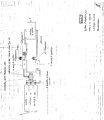
- the invention presented here solves the problem of autonomy by coupling three bottles to the motor via a device called pneumatic rotary distributor.
- bottles of compressed air are needed (including a vacuum for refilling) coupled to the pneumatic rotary distributor which alternates the supply and the exhaust through the rotating central part (board 1 & 3), the exhaust for the empty bottle and feeding for the full bottle.
- This system is a closed circuit system, allowing the use of other more compressible gas.
- DRP pneumatic rotary distributor
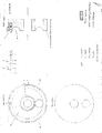
- plate 1 to 6 The heart of the device is called pneumatic rotary distributor or DRP (plate 1 to 6)
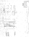
- the latter is composed of three cylindrical juxtaposed elements whose central portion is rotatable by means of a pneumatic actuator powered by the exhaust regulating vesicle by an electronically controlled arrival for this purpose (plate 5).
- This part of the DRP is used to supply the engine with compressed air and the recovery of the exhaust to fill another air cylinder.
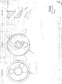
- the distributive fixed part on the bottle side of the DRP comprises 3 orifices, one for each bottle (plate 1 & 4) surrounded by 2 Teflon strips ensuring the seal between the distributive part on the bottle side and the rotating part of the DRP, this fixed part home the gag coupling device (plate 4) ensuring the sealing and wedging of the rotating central part.
- the distributive fixed part on the engine side has 2 orifices, the central orifice for the exhaust and the 2nd one for the supply is crowned by an annular stub allowing the passage of the air whatever the position of the rotating part of the DRP (plate 1 & 2), all encircled by 2 Teflon ring rods ensuring tightness and minimum resistance during rotation of the central part.
- the distributive fixed motor part also comprises a locking device (plate 2) actuated by a pneumatic system pushing the pen inwardly which makes the latch skip, thereby unlocking the device, the locking is done by simply pressing a spring which pushes back the latch outwards, there are 3 lock latches distant 120 °.
- a locking device plate 2 actuated by a pneumatic system pushing the pen inwardly which makes the latch skip, thereby unlocking the device, the locking is done by simply pressing a spring which pushes back the latch outwards, there are 3 lock latches distant 120 °.
- the rotating central part of the DRP (board 1 & 3) is also ringed with 2 Teflon rings on each side of the room and has 2 inclined holes allowing connection between the inlet and the full bottle and the exhaust with the bottle empty, this piece rotates at a stroke of 120 °, the motor side of this element also includes 3 knockouts 120 ° apart accommodating the locking system, these burrs have an inclined plane thus helping the rotation of the workpiece through the spring of the system. locking that pushes the latch, terminated by a wheel, towards the central portion to ensure a complete blockage of the device when the latches are in place (plate 3).
Landscapes
- Engineering & Computer Science (AREA)
- Mechanical Engineering (AREA)
- General Engineering & Computer Science (AREA)
- Filling Or Discharging Of Gas Storage Vessels (AREA)
- Structures Of Non-Positive Displacement Pumps (AREA)
Applications Claiming Priority (1)
| Application Number | Priority Date | Filing Date | Title |
|---|---|---|---|
| CH12212009A CH701606B1 (fr) | 2009-08-05 | 2009-08-05 | Distributeur rotatif pneumatique pour le couplage d'un moteur à air comprimé à trois bouteilles d'air comprimé |
Publications (1)
| Publication Number | Publication Date |
|---|---|
| EP2282008A2 true EP2282008A2 (de) | 2011-02-09 |
Family
ID=43066991
Family Applications (1)
| Application Number | Title | Priority Date | Filing Date |
|---|---|---|---|
| EP20090405156 Withdrawn EP2282008A2 (de) | 2009-08-05 | 2009-09-14 | Zuführsystem für Druckluftmotor mit sofortiger Wiederaufladung |
Country Status (2)
| Country | Link |
|---|---|
| EP (1) | EP2282008A2 (de) |
| CH (1) | CH701606B1 (de) |
-
2009
- 2009-08-05 CH CH12212009A patent/CH701606B1/fr not_active IP Right Cessation
- 2009-09-14 EP EP20090405156 patent/EP2282008A2/de not_active Withdrawn
Also Published As
| Publication number | Publication date |
|---|---|
| CH701606A2 (fr) | 2011-02-15 |
| CH701606B1 (fr) | 2012-11-15 |
Similar Documents
| Publication | Publication Date | Title |
|---|---|---|
| CA2110274C (fr) | Ensemble d'alimentation en gaz industriel d'un appareil utilisateur portable | |
| EP3181238B2 (de) | Form kodierte quetschventile. | |
| EP2043910A1 (de) | System zur übertragung einer flüssigkeit, wie verflüssigtes erdgas aus einem schiff als flüssigerdgasträger und schwimmende oder feste einheit | |
| US9500062B2 (en) | Valve device of a wellhead Christmas tree assembly | |
| US8371341B2 (en) | Magnetically actuated vapor recovery valve | |
| US9567962B2 (en) | Flow-control assembly comprising a turbine-generator cartridge | |
| FR2998867A1 (fr) | Dispositif d'alimentation et de repartition de fluide | |
| EP2282008A2 (de) | Zuführsystem für Druckluftmotor mit sofortiger Wiederaufladung | |
| CN101644348B (zh) | 气动工具的马达组件 | |
| US7380835B2 (en) | Single bore high flow junction plate | |
| WO2008114048A2 (en) | Fluid coupling, system for varying the deadweight of apparatus in which such a coupling can be incorporated, and a fluid control valve incorporable in such a system | |
| CN102016281A (zh) | 加压气体接收设备、分配器-接收设备组件以及相应的供应系统 | |
| EP1217489B1 (de) | Fluidentspannungssystem mit voneinander trennbaren Modulen | |
| FR3014488A1 (fr) | Vanne pour circuit carburant d'un moteur d'aeronef | |
| CN103133186A (zh) | 用于气体发动机的燃料供给系统 | |
| EP1267065B1 (de) | Gaszuführvorrichtung für Brennkraftmaschine | |
| FR2912488A1 (fr) | Raccord a verrouillage automatique pour fluides medicaux, utilisation dans un reseau de distribution et reseau correspondant. | |
| EP2576332B1 (de) | Installation zum transport einer flüssigkeit zwischen zwei schiffen | |
| EP3647636B1 (de) | Regulierungsventil für flüssigkeitsfluss, das mit einem elektrischen stellglied ausgestattet ist, und ein solches ventil umfassendes system | |
| FR2798426A1 (fr) | Dispositif d'admission variable pour moteur thermique et boisseau pour un tel dispositif | |
| FR2965559A1 (fr) | Installation de transfert de fluide | |
| EP3825592B1 (de) | Dreiwege-magnetventil mit zwei stellungen | |
| FR2596130A1 (fr) | Dispositif de securite pour conduit flexible d'alimentation en eau pour appareils electromenagers | |
| FR2709329A1 (fr) | Vanne à commande directe, pour l'alimentation en carburant d'un moteur, en particulier d'aéronef. | |
| BE1011007A3 (fr) | Vanne en ligne autoverrouillable. |
Legal Events
| Date | Code | Title | Description |
|---|---|---|---|
| PUAI | Public reference made under article 153(3) epc to a published international application that has entered the european phase |
Free format text: ORIGINAL CODE: 0009012 |
|
| AK | Designated contracting states |
Kind code of ref document: A2 Designated state(s): AT BE BG CH CY CZ DE DK EE ES FI FR GB GR HR HU IE IS IT LI LT LU LV MC MK MT NL NO PL PT RO SE SI SK SM TR |
|
| AX | Request for extension of the european patent |
Extension state: AL BA RS |
|
| STAA | Information on the status of an ep patent application or granted ep patent |
Free format text: STATUS: THE APPLICATION IS DEEMED TO BE WITHDRAWN |
|
| 18D | Application deemed to be withdrawn |
Effective date: 20120403 |