EP2281998A2 - Verfahren und Vorrichtung für Unterwasserbohrlocheingriff und Unterwasserbohrlochkopfrückzug - Google Patents
Verfahren und Vorrichtung für Unterwasserbohrlocheingriff und Unterwasserbohrlochkopfrückzug Download PDFInfo
- Publication number
- EP2281998A2 EP2281998A2 EP10251128A EP10251128A EP2281998A2 EP 2281998 A2 EP2281998 A2 EP 2281998A2 EP 10251128 A EP10251128 A EP 10251128A EP 10251128 A EP10251128 A EP 10251128A EP 2281998 A2 EP2281998 A2 EP 2281998A2
- Authority
- EP
- European Patent Office
- Prior art keywords
- tool
- wellhead
- subsea
- casing string
- grip
- Prior art date
- Legal status (The legal status is an assumption and is not a legal conclusion. Google has not performed a legal analysis and makes no representation as to the accuracy of the status listed.)
- Granted
Links
Images


Classifications
-
- E—FIXED CONSTRUCTIONS
- E21—EARTH OR ROCK DRILLING; MINING
- E21B—EARTH OR ROCK DRILLING; OBTAINING OIL, GAS, WATER, SOLUBLE OR MELTABLE MATERIALS OR A SLURRY OF MINERALS FROM WELLS
- E21B23/00—Apparatus for displacing, setting, locking, releasing or removing tools, packers or the like in boreholes or wells
-
- E—FIXED CONSTRUCTIONS
- E21—EARTH OR ROCK DRILLING; MINING
- E21B—EARTH OR ROCK DRILLING; OBTAINING OIL, GAS, WATER, SOLUBLE OR MELTABLE MATERIALS OR A SLURRY OF MINERALS FROM WELLS
- E21B29/00—Cutting or destroying pipes, packers, plugs or wire lines, located in boreholes or wells, e.g. cutting of damaged pipes, of windows; Deforming of pipes in boreholes or wells; Reconditioning of well casings while in the ground
- E21B29/002—Cutting, e.g. milling, a pipe with a cutter rotating along the circumference of the pipe
- E21B29/005—Cutting, e.g. milling, a pipe with a cutter rotating along the circumference of the pipe with a radially-expansible cutter rotating inside the pipe, e.g. for cutting an annular window
-
- E—FIXED CONSTRUCTIONS
- E21—EARTH OR ROCK DRILLING; MINING
- E21B—EARTH OR ROCK DRILLING; OBTAINING OIL, GAS, WATER, SOLUBLE OR MELTABLE MATERIALS OR A SLURRY OF MINERALS FROM WELLS
- E21B29/00—Cutting or destroying pipes, packers, plugs or wire lines, located in boreholes or wells, e.g. cutting of damaged pipes, of windows; Deforming of pipes in boreholes or wells; Reconditioning of well casings while in the ground
- E21B29/12—Cutting or destroying pipes, packers, plugs or wire lines, located in boreholes or wells, e.g. cutting of damaged pipes, of windows; Deforming of pipes in boreholes or wells; Reconditioning of well casings while in the ground specially adapted for underwater installations
-
- E—FIXED CONSTRUCTIONS
- E21—EARTH OR ROCK DRILLING; MINING
- E21B—EARTH OR ROCK DRILLING; OBTAINING OIL, GAS, WATER, SOLUBLE OR MELTABLE MATERIALS OR A SLURRY OF MINERALS FROM WELLS
- E21B33/00—Sealing or packing boreholes or wells
- E21B33/02—Surface sealing or packing
- E21B33/03—Well heads; Setting-up thereof
- E21B33/035—Well heads; Setting-up thereof specially adapted for underwater installations
-
- E—FIXED CONSTRUCTIONS
- E21—EARTH OR ROCK DRILLING; MINING
- E21B—EARTH OR ROCK DRILLING; OBTAINING OIL, GAS, WATER, SOLUBLE OR MELTABLE MATERIALS OR A SLURRY OF MINERALS FROM WELLS
- E21B47/00—Survey of boreholes or wells
- E21B47/001—Survey of boreholes or wells for underwater installation
-
- B—PERFORMING OPERATIONS; TRANSPORTING
- B24—GRINDING; POLISHING
- B24C—ABRASIVE OR RELATED BLASTING WITH PARTICULATE MATERIAL
- B24C1/00—Methods for use of abrasive blasting for producing particular effects; Use of auxiliary equipment in connection with such methods
- B24C1/04—Methods for use of abrasive blasting for producing particular effects; Use of auxiliary equipment in connection with such methods for treating only selected parts of a surface, e.g. for carving stone or glass
- B24C1/045—Methods for use of abrasive blasting for producing particular effects; Use of auxiliary equipment in connection with such methods for treating only selected parts of a surface, e.g. for carving stone or glass for cutting
-
- B—PERFORMING OPERATIONS; TRANSPORTING
- B24—GRINDING; POLISHING
- B24C—ABRASIVE OR RELATED BLASTING WITH PARTICULATE MATERIAL
- B24C3/00—Abrasive blasting machines or devices; Plants
- B24C3/32—Abrasive blasting machines or devices; Plants designed for abrasive blasting of particular work, e.g. the internal surfaces of cylinder blocks
- B24C3/325—Abrasive blasting machines or devices; Plants designed for abrasive blasting of particular work, e.g. the internal surfaces of cylinder blocks for internal surfaces, e.g. of tubes
Definitions
- Embodiments of the present invention generally relate to a subsea well. More particularly, embodiments of the invention relate to methods and apparatus for subsea well intervention operations, including retrieval of a wellhead from a subsea well.
- the subsea well closing process typically includes recovering the wellhead from the subsea well using a conventional wellhead retrieval operation.
- a retrieval assembly equipped with a casing cutter is lowered on a work string from a floating rig until the retrieval assembly is positioned over the subsea wellhead.
- the casing cutter is lowered into the wellbore as the retrieval assembly is lowered onto the wellhead.
- the casing cutter is actuated to cut the casing by using the work string.
- the cutter may be powered by rotating the work string from the floating rig.
- the floating rig Since the work string is used to manipulate the retrieval assembly and the casing cutter, the floating rig is required at the surface to provide the necessary support and structure for the work string. Even though the subsea wellhead may be removed in this manner, the use of the floating rig and the work string can be costly and time consuming. Therefore, there is a need for an improved method and apparatus for subsea wellhead retrieval.
- the present invention generally relates to methods and apparatus for subsea well intervention operations, including retrieval of a wellhead from a subsea well.
- a method of performing an operation in a subsea well comprises the step of positioning a tool proximate a subsea wellhead.
- the tool has at least one grip member and the tool is attached to a downhole assembly.
- the method also comprises the step of clamping the tool to the subsea wellhead by moving the at least one grip member into engagement with a profile on the subsea wellhead.
- the method further comprises the step of applying an upward force to the tool thereby enhancing the grip between the grip member and the profile on the subsea wellhead.
- the method comprises the step of performing the operation in the subsea well by utilizing the downhole assembly.
- an apparatus for use in a subsea well comprises a grip member movable between an unclamped position and a clamped position, wherein the grip member in the clamped position applies a grip force to a profile on the subsea wellhead. Additionally, the apparatus comprises a lifting assembly configured to generate an upward force which increases the grip force applied by the grip member.
- a method of performing an operation in a subsea well comprises the step of positioning a tool proximate a subsea wellhead.
- the tool has at least one grip member and a lock member.
- the tool is also attached to a downhole assembly.
- the method further comprises the step of moving the at least one grip member from an unclamped position to a clamped position in which the grip member engages the subsea wellhead.
- the method also comprises the step of hydraulically activating the lock member such that the lock member engages a portion of the grip member thereby retaining the grip member in the clamped position.
- the method comprises the step of performing the operation in the subsea well by utilizing the downhole assembly.
- an apparatus for use in a subsea well comprises a grip member for engaging a subsea wellhead, wherein the grip member is movable between an unclamped position and a clamped position.
- the apparatus further comprises a lock member movable between an unlocked position and a locked position upon activation of a hydraulic cylinder, wherein the lock member in the locked position retains the grip member in the clamped position.
- a method of cutting a casing string in a subsea well comprises the step of positioning a tool proximate a subsea wellhead.
- the tool has at least one grip member and the tool is attached to a cutting assembly.
- the method further comprises the step of operating the at least one grip member to clamp the tool to the subsea wellhead.
- the method also comprises the step of cutting the casing string below the subsea wellhead by utilizing the cutting assembly.
- the method comprises the step of applying an upward force to the tool during the cutting of the casing string which is at least equal to an axial reaction force generated from cutting the casing string, wherein at least a portion of the upward force is created by a cylinder member in the tool that acts on the subsea wellhead.
- an apparatus for cutting a casing string in a subsea well comprises a cutting assembly configured to cut the casing string.
- the apparatus also comprises a grip member for engaging a subsea wellhead, the grip member movable between an unclamped position and a clamped position.
- the apparatus comprises a lifting assembly configured to generate an upward force which is at least equal to an axial reaction force generated from cutting the casing string, wherein the lifting assembly comprises a cylinder and piston arrangement that is configured to act upon a portion of the subsea wellhead.
- a method of gripping a subsea wellhead comprises the step of positioning a tool proximate the subsea wellhead.
- the tool has at least one grip member.
- the method further comprises the step of clamping the tool to the subsea wellhead by moving the at least one grip member into engagement with a profile on the subsea wellhead.
- the method comprises the step of applying an upward force to the tool thereby enhancing the grip between the grip member and the profile on the subsea wellhead.
- Figure 1 is an isometric view of a subsea wellhead intervention and retrieval tool according to one embodiment of the invention.
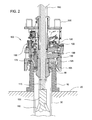
- Figure 2 is a view illustrating the placement of the tool on a wellhead.
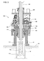
- Figure 3 is a view illustrating the tool engaging the wellhead.
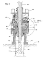
- Figure 4 is a view illustrating the tool cutting a casing string below the wellhead.
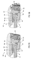
- Figures 5A and 5B are enlarged views illustrating the components of the tool.
- Figure 6 is a view illustrating the tool after the casing string has been cut.
- Figure 7 is a view illustrating a subsea wellhead intervention and retrieval tool with a perforating tool.
- Figure 8 is a view illustrating a subsea wellhead intervention and retrieval tool with the perforating tool disposed on a wireline.
- Figure 9 is a view illustrating a subsea wellhead intervention and retrieval tool with the perforating tool.
- Figure 10 is a view illustrating a subsea wellhead intervention and retrieval tool with a cutter assembly.
- Figure 11 is a view illustrating a subsea wellhead intervention and retrieval tool with an explosive charge device.
- Embodiments of the present invention generally relate to methods and apparatus for subsea well intervention operations, including retrieval of a wellhead from a subsea well. To better understand the aspects of the present invention and the methods of use thereof, reference is hereafter made to the accompanying drawings.
- Figure 1 shows a subsea wellhead intervention and retrieval tool 100 according to one embodiment of the invention.
- the tool 100 includes a shackle 210 and a mandrel 195 for connection to a conveyance member 202, such as a cable.
- a conveyance member 202 such as a cable.
- the use of cable with the tool 100 allows for greater flexibility because the cable may be deployed from an offshore location that includes a crane rather than using a floating rig with a work string as in the conventional wellhead retrieval operation.
- the conveyance member may be an umbilical, coil tubing, wireline or jointed pipe.
- the conveyance member 202 is used to lower the tool 100 into the sea to a position adjacent the subsea wellhead.
- a power source (not shown), such as a hydraulic pump, pneumatic pump or a electrical control source, is attached to the tool 100 via an umbilical cord (not shown) connected to connectors 205 to manipulate and/or monitor the operation of the tool 100.
- the power source is attached to a control system 230 of the tool 100.
- the control system 230 may include a manifold arrangement that integrates one or more cylinders of the tool 100.
- the manifold arrangement may include a filtration system and a plurality of pilot operated check valves which allows the cylinders of the tool to function in a forward direction or a reverse direction.
- the manifold arrangement allows the cylinders to operate independently from the other components in the tool 100.
- the functionality of the cylinders will be discussed herein.
- the control system 230 may also include data sensors, such as pressure sensors and temperature sensors that generate data regarding the components of the tool 100.
- the data may be used to monitor the operation of the tool 100 and/or control the components of the tool 100. Further, the data may be used locally by an onboard computer or by the ROV. The data may also be used remotely by sending the data back to the surface via the ROV or via an umbilical attached to the tool.
- the power source for controlling the control system 230 of the tool 100 is typically located near the surface.
- the power source may be configured to pump fluid from the offshore location through the umbilical cord connected to the connectors 205 in order to operate the components of the tool 100 such as arms 125 and wedge blocks 150 as described herein.
- the tool 100 may be manipulated using a remotely operated underwater vehicle (ROV).
- ROV remotely operated underwater vehicle
- the ROV may attach to the tool 100 via a stab connector 215 and then control the control system 230 of the tool 100 in a similar manner as described herein.
- the ROV may also manipulate the position of the tool 100 relative to the wellhead by using handler members 220.
- the tool 100 may be attached to a downhole assembly such as a motor 115 and a rotary cutter assembly 105.
- the motor 115 may be an electric motor or a hydraulic motor such as a mud motor.
- the rotary cutter assembly 105 includes a plurality of blades 110 which are used to cut the casing.
- the blades 110 are movable between a retracted position and an extended position.
- the tool 100 may use an abrasive cutting device to cut the casing instead of the rotary cutter assembly 105.
- the abrasive cutting device may include a high pressure nozzle configured to output high pressure fluid to cut the casing.
- abrasive cutting technology allows the tool 100 to cut through the casing with substantially no downward pull or torque transmission to the wellhead which is common with the rotary cutter assembly 105.
- the tool 100 may use a high energy source such as laser, high power light, or plasma to cut the casing.
- the high energy cutting system may be incorporated into the tool 100 or conveyed to or through the tool 100 via a transmission system.
- Suitable cutting systems may use well fluids, and/or water to cut through multiple casings, cement and voids. The cutting systems may also reduce downward pull and subsequent reactive torque transmission to the wellhead.
- Figure 2 is a view illustrating the placement of the tool 100 on a wellhead 10.
- the tool 100 is lowered via the conveyance member until the tool 100 is positioned proximate the top of the wellhead 10 disposed on a seafloor 20.
- the motor 115 and the cutter assembly 105 are lowered into the wellhead 10 such that the blades 110 of the cutter assembly 105 are adjacent the casing string 30 attached to the wellhead 10.
- the wellhead 10 includes a profile 50 at an upper end.
- the profile 50 may have different configurations depending on which company manufactured the wellhead 10.
- the arms 125 of the tool 100 include a matching profile 165 to engage the wellhead 10 during the wellhead retrieval operation.
- the arms 125 or the profile 165 on the arms 125 may be changed (e.g., removed and replaced) with a different profile in order to match the specific profile on the wellhead 10 of interest.
- the arms 125 are shown in an unclamped position in Figure 2 and in a clamped position in Figure 3 .
- Figure 3 illustrates the tool 100 engaging the wellhead 10.
- the tool 100 includes an actuating cylinder 135 (e.g. piston and cylinder arrangement) that is attached to the arm 125.
- the arms 125 rotate around pivot 130 from the unclamped position to the clamped position in order to engage the wellhead 10.
- the arms 125 may be individually activated by a respective cylinder 135 or collectively activated by one or more cylinders.
- the profile 165 on the arms 125 mate with the corresponding profile 50 on the wellhead 10.
- the arms 125 are locked in place by activating a locking cylinder 155 (e.g.
- wedge block 150 which causes a wedge block 150 to slide along a surface of the arm 125 as shown in Figure 4 .
- the movement of the wedge block 150 prevents the arms 125 from rotating around the pivot 130 to the clamped position.
- the wedge blocks 150 may be individually activated by the respective cylinder 155 or collectively activated by one or more cylinders.
- Figure 4 is a view illustrating the tool 100 cutting a casing string 30 below the wellhead 10.
- an optional cylinder 180 e.g. piston and cylinder arrangement
- a shoe 175 to act upon a surface 25 of the wellhead 10 and axially lift the tool 100 relative to the wellhead 10.
- the axial movement of the tool 100 relative to the wellhead 10 allows for active clamping of the tool 100 on the wellhead 10.
- the profile 165 on the arms 125 moves into maximum contact with the profile 50 on the wellhead 10 such that the tool 100 is clamped on the wellhead 10 and will not rotate (or spin) relative to the wellhead 10 when the rotary cutter assembly 105 is in operation.
- reactive torque resistance is provided for the mechanical cutting system.
- the motor 115 activates the rotary cutter assembly 105 and the blades 110 move from the retracted position to the extended position as illustrated in Figure 3 to Figure 4 . Thereafter, the casing string 30 is cut by the rotary cutter assembly 105.
- the cylinders 135, 155, 180 may be independently operated by the power source or by the ROV. Additionally, it is contemplated that cylinders 135, 155, 180 may include any suitable number of cylinders as necessary to perform the intended function.
- Figures 5A and 5B are enlarged views illustrating the components of the tool 100.
- the conveyance member may be pulled from the surface to enhance the clamping of the tool 100 on the wellhead 10.
- the upward force applied to the tool 100 by the conveyance member causes an inner mandrel 170 to move from a first position ( Figure 5A ) to a second position ( Figure 5B ).
- the inner mandrel 170 includes a key member 190.
- the key member 190 may be a separate component attached to the inner mandrel 170 as illustrated or the key member 190 may be formed as part of the mandrel 170 as a single piece.
- the inner mandrel 170 has moved axially up relative to the wellhead 10.
- the inner mandrel 170 (and/or the key member 190) contacts and applies a force to a surface 120 of the arms 125 which increases (or enhances) the gripping force applied by the arms 125 to the profile 50 on the wellhead 10.
- the inner mandrel 170 applies the force to the arms 125 and that force is transferred due to the shape of each arm 125 (i.e. lever) and the pivot 130 into the gripping surface which grips the profile 50, thereby enhancing the grip on the profile 50.
- the conveyance member connected to the tool 100 may also be pulled from the surface (i.e., offshore location) to create tension in the wellhead 10 and the casing string 30.
- the tension created by pulling on the conveyance member may be useful during the cutting operation because tension in the casing string 30 typically prevents the cutters 110 of the rotary cutter assembly 105 from jamming (or become stuck) as the cutters 110 cut through the casing string 30.
- the upward force created by pulling on the conveyance member is preferably at least equal to any downward force generated during the cutting operation. The upward force is typically maintained during the cutting operation. Optionally, the upward force may also be sufficient to counteract the wellhead assembly deadweight.
- the inner mandrel 170 in the tool 100 may move between the first position as shown in Figure 5A and the second position as shown in Figure 5B .
- a portion of the inner mandrel 170 (and/or the key member 190) is positioned proximate a stop block 185 as shown in Figure 5A .
- the inner mandrel 170 has moved axially down relative to the wellhead 10 which typically occurs when the tension in the conveyance member attached to the tool 100 has been minimized.
- the second position a portion of the inner mandrel 170 is positioned proximate the surface 120 of the arms 125.
- the inner mandrel 170 has moved axially up relative to the wellhead 10 which typically occurs when the tension in the conveyance member attached to the tool 100 has been increased. Further, in the second position, the inner mandrel 170 (and/or the key member 190) contacts and applies a force to the surface 120 of the arms 125 which increases (or enhances) the gripping force applied by the arms 125 to the profile 50 on the wellhead 10. In other words, the inner mandrel 170 applies the force to the arms 125 and that force is transferred due to the shape of each arm 125 (i.e. lever) and the pivot 130 into the gripping surface which grips the profile 50, thereby enhancing the grip on the profile 50.
- each arm 125 i.e. lever
- Figure 6 is a view illustrating the tool 100 after the casing string 30 has been cut.
- the cutters 110 on the rotary cutter assembly 105 continue to operate until a lower portion of the casing string 30 is disconnected from an upper portion of the casing string 30.
- the rotary cutter assembly 105 is deactivated which causes the cutters 110 to move from the extended position to the retracted position.
- the tool 100, the wellhead 10, and a portion of the casing string 30 are lifted from the seafloor 20 by pulling on the conveyance member attached to the tool 100 until the wellhead 10 is removed from the sea.
- the cylinders 135, 155, 180 may be systematically deactivated to release the tool 100 from the wellhead 10.
- the tool 100 is lowered into the sea via the conveyance member until the tool 100 is positioned proximate the top of the wellhead 10 disposed on the seafloor 20.
- the cylinder 135 is actuated to cause the arms 125 to rotate around pivot 130 to engage the wellhead 10.
- the arms 125 are locked in place by actuating the cylinder 155 which causes the wedge block 150 to slide along the surface of the arms 125 to prevent the arms 125 from rotating around the pivot 130 to the unclamped position.
- the cylinder 180 is activated which causes the shoe 175 to act upon the surface 25 of the wellhead 10 and axially lift the tool 100 relative to the wellhead 10.
- the axial movement of the tool 100 relative to the wellhead 10 allows for active clamping of the tool 100 on the wellhead 10.
- This sequential function is automatically controlled by the onboard manifold or can be manually sequenced as required by the operator or via a ROV.
- the conveyance member connected to the tool 100 is pulled from the surface (i.e. offshore location) to create tension on the wellhead assembly 10 and the casing string 30.
- the motor 115 activates the rotary cutter assembly 105 and the blades 110 move from the retracted position to the extended position to cut through the casing string or multiple casing strings 30.
- the wellhead assembly deadweight is born mechanically to leverage the load for increased clamping force on the external wellhead profile to maximize reactive torque resistance capability for high torque cutting.
- Axial load cylinder 180 function to stabilize and preload grip arms during cutting operation. After the casing string 30 is cut, the tool 100, the wellhead 10 and a portion of the casing string 30 is lifted from the seafloor 20 by pulling on the conveyance member attached to the tool 100.
- the cylinders 135, 155, 180 may be systematically deactivated to release the tool 100 from the wellhead 10. At any time during operation, the cylinder function sets 135, 155, 180 may be independently controlled and shut down or reversed for function testing, unsuccessful wellhead release, or maintenance as required through surface controls or remotely using a ROV in case of umbilical failure.
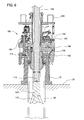
- Figure 7 is a view illustrating a subsea wellhead intervention and retrieval tool 200 attached to a perforating tool 215.
- the components of the tool 200 that are similar to the components of the tool 100 will be labeled with the same reference indicator.
- the tool 200 has engaged the wellhead 10 in a similar manner as described herein.
- the tool 200 may be attached to an optional packer member 205 that is configured to seal an annulus formed between a tubular member 220 and the casing string 30 attached to the wellhead 10.
- the packer member 205 may be any type of packer known in art, such as a hydraulic packer or a mechanical packer.
- the packer member 205 may be used for isolation or well control. Upon activation of the packer member 205, the packer member 205 moves from a first diameter and a second larger diameter. Upon deactivation, the packer member 205 moves from the second larger diameter to the first diameter.
- the packer member 205 may be activated and deactivated multiple times.
- the tool 200 may be attached to an optional ported sub 210 and the perforating tool 215 mounted on a pipe 225.
- the pipe 225, the ported sub 210 and the perforating tool 215 may be an integral part of the tool 200 or a separate component that is lowered through the tool 200 via a conveyance member, such as pipe, coiled tubing or an umbilical.
- the ported sub 210 may be used in conjunction with the packer member 205 to monitor, control pressure or bleed-off pressure, gas or liquid.
- the ported sub 210 may also be used to pump cement into the wellbore.
- the ported sub 210 is selectively movable between an open position and a closed position multiple times.
- the perforating tool 215 is generally a device used to perforate (or punch) the casing string 30 or multiple casing strings, such as casing strings 30, 40.
- the perforating tool 215 includes several shaped explosive charges that are selectively activated to perforate the casing string. It is to be noted that the perforating tool 215 may also be used to sever or cut the casing string 30 so that the wellhead 10 may be removed in a similar manner as described herein.
- the tool 200 is lowered into the sea via the conveyance member and attached to the wellhead 10 disposed on the seafloor 20 in a similar manner as set forth herein.
- the optional packer 205 may be activated.
- the ported sub 210 may also be activated and used as set forth herein.
- the perforating tool 215 may be used to perforate (or cut) the casing string.
- the tool 200 may further be used to remove the wellhead 10 in a similar manner as described herein.
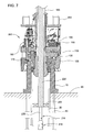
- Figure 8 is a view illustrating a subsea wellhead intervention and retrieval tool 250 with the perforating tool 215 disposed on a wireline 255.
- the components of the tool 250 that are similar to the components of the tools 100, 200 will be labeled with the same reference indicator.
- the tool 250 has engaged the wellhead 10 in a similar manner as described herein.
- the perforating tool 215 has been positioned in the casing string 30 by utilizing the wireline 255. This arrangement may be useful if multiple areas are to be perforated by the perforating tool 215.
- the use of wireline 255 allows the capability of running the perforating tool 215 in and out of the wellbore multiple times (or runs).
- the tubular member 220 is open ended thereby allowing fluid flow to be pumped through the tubular member 220.
- the tool 250 is lowered into the sea via the conveyance member and attached to the wellhead 10 disposed on the seafloor 20 in a similar manner as set forth herein.
- the optional packer 205 may be activated to create a seal between the tubular member 220 and the casing string 30.
- the perforating tool 215 may be positioned in the casing string 30 by utilizing the wireline 255 and then activated to perforate (or cut) the casing string.
- the tool 250 may further be used to remove the wellhead 10 in a similar manner as described herein.
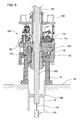
- Figure 9 is a view illustrating a subsea wellhead intervention and retrieval tool 300 with the perforating tool 215.
- the components of the tool 300 that are similar to the components of tools 100, 200 will be labeled with the same reference indicator.
- the tool 300 has engaged the wellhead 10 in a similar manner as described herein.
- the tool 300 includes the ported sub 210 and the perforating tool 215.
- the perforating tool 215 may be used to perforate (or sever) the casing string 30 or any number of casing strings, such as casing strings 30, 60.
- the ported sub 210 may be used in a pressure test and/or to distribute cement 55 which is pumped from the surface.
- the tool 300 is lowered into the sea via the conveyance member and attached to the wellhead 10 disposed on the seafloor 20 in a similar manner as set forth herein.
- the optional packer 205 may be activated and the ported sub 210 may used as set forth herein.
- the perforating tool 215 may be operated to perforate (or cut) the casing string.
- the tool 300 may further be used to remove the wellhead 10 in a similar manner as described herein.
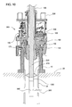
- Figure 10 is a view illustrating a subsea wellhead intervention and retrieval tool 350 attached to a cutter assembly 360.
- the components of the tool 350 that are similar to the components of the tool 100 will be labeled with the same reference indicator.
- the tool 350 has engaged the wellhead 10 in a similar manner as described herein.
- the cutter assembly 360 uses a cutting stream 365 to cut the casing string 30.
- the cutter assembly 360 is a laser cutter.
- the laser cutter would be connected to the surface via a fiber optic bundle (not shown).
- the fiber optic bundle would be used to transmit light energy to the cutter assembly 360 from lasers on the surface.
- the cutter assembly 360 would direct the light energy by using a series of lenses (not shown) in the cutter assembly 360 toward the casing string 30.
- the light energy i.e. cutting stream 365
- the cutter assembly 360 is a plasma cutter.
- the plasma cutter would be connected to the surface via a conduit line (not shown).
- the conduit line would be used to transmit pressurized gas to the cutter assembly 360.
- the gas is blown out of a nozzle in the cutter assembly 360 at a high speed, at the same time an electrical arc is formed through that gas from the nozzle to the surface being cut, turning some of that gas to plasma.
- the plasma is sufficiently hot to melt the metal of the casing string 30.
- the plasma i.e. cutting stream 365
- the cutter assembly 360 is an abrasive cutter.
- the abrasive cutter would be connected to the surface via a fluid conduit (not shown).
- the fluid conduit would be used to transmit pressurized fluid having abrasives to the cutter assembly 360.
- the pressurized fluid (with abrasives) is blown out of a nozzle in the cutter assembly 360.
- the pressurized fluid i.e. cutting stream 365
- a chemical or a high energy media may be used with the cutter assembly 360 to cut (or perforate) the casing string 30.
- the tool 350 includes an optional rotating device 355 configured to rotate the cutter assembly 360.
- the rotating device 355 may be controlled at the surface or downhole.
- the rotating device 355 may be powered by electric power or hydraulic power.
- the rotating device 355 will rotate the cutter assembly 360 in a 360 degree rotation in order to cut the casing string 30.
- the speed, direction and the timing of the rotation will also be controlled by the rotating device 355 in order to allow the cutting stream 365 to sever (or perforate) the casing string 30.
- the tool 350 may be attached to an optional anchor device 370 to anchor the tool 350 to the casing string 30.
- the anchor device 370 may include radially extendable members that grip the casing string 30 upon activation of the anchor device 370.
- the anchor device 370 is used to stabilize (or centralize) the cutter assembly 360 in the casing string 30.
- the tool 350 is lowered into the sea via the conveyance member and attached to the wellhead 10 disposed on the seafloor 20 in a similar manner as set forth herein.
- the optional anchoring device 370 may be used to stabilize (or centralize) the cutter assembly 360 in the casing string 30.
- the cutter assembly 360 may be activated to perforate (or cut) the casing string and the cutter assembly may be rotated by using the rotating device 355.
- the tool 350 may further be used to remove the wellhead 10 in a similar manner as described herein.
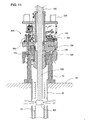
- Figure 11 is a view illustrating a subsea wellhead intervention and retrieval tool 400 with an explosive charge device 405.
- the components of the tool 400 that are similar to the components of tools 100, 200 will be labeled with the same reference indicator.
- the tool 400 has engaged the wellhead 10 in a similar manner as described herein.
- the tool 400 includes the explosive charge device 405 for cutting (or perforating) the casing string 30 or any number of casing strings.
- the explosive charge device 405 includes several shaped explosive charges that are selectively activated to cut (or perforate) the casing string 30.
- the explosive charge device 405 may also include a single massive explosive charge. If the casing string 30 is to be cut, the explosive charge device 405 may include a 360 degree charge which will cut (or sever) the casing string 30 upon activation.
- the explosive charge device 405 is part of the tool 400. It is to be noted, however, that the explosive charge device 405 could be a separate device that is lowered through the tool 405 via a wireline or another type of conveyance member, such as coil tubing, jointed pipe or an umbilical.
- the tool 400 is lowered into the sea via the conveyance member and attached to the wellhead 10 disposed on the seafloor 20 in a similar manner as set forth herein.
- the explosive charge device 405 may activated to perforate (or cut) the casing string.
- the tool 400 may also be used to remove the wellhead 10 in a similar manner as described herein.
- the subsea tool described herein may be used for subsea well intervention operations, including retrieval of a wellhead from a subsea well.
- one or more systems or subsystems of the subsea tool may be controlled, monitored or diagnosed via Radio Frequency Identification Device (RFID) or a radio antenna array.
- RFID Radio Frequency Identification Device
- the components of the subsea tool may be activated by using a RFID electronics package with a passive RFID tag or an active RFID tag.
- one or more components in the subsea tool may include the electronics package that activates the component when the active (or passive) RFID tag is positioned proximate a suitable sensor.
- the subsea tool having a component with the electronics package is lowered into the sea via the conveyance member and positioned proximate the wellhead disposed on the seafloor in a similar manner as set forth herein. Thereafter, the active (or passive) RFID tag is pumped through an umbilical connected to the tool or lowered into the sea. When the active (or passive) RFID tag is detected, the relevant component may be activated.
- the electronics package in the tool may sense the active (or passive) RFID tag then send a control signal to actuate the gripping arm.
- the same electronics package may sense another active (or passive) RFID tag and then send another control signal to actuate the wedge block assembly.
- the same electronics package may sense a further active (or passive) RFID tag and then send a further control signal to actuate the lifting cylinders.
- the tool may be controlled by using the electronics package with the active (or passive) RFID tags.
- an electronics package with the active (or passive) RFID tags may be used to activate and control a downhole assembly attached to the tool.
- the embodiments describe herein relate to a single subsea wellhead intervention and retrieval tool. However, it is contemplated that multiple subsea wellhead intervention and retrieval tools may be used together in a system. Each subsea wellhead intervention and retrieval tool may be independently powered or linked to a primary subsea power source for simultaneous onsite multiple unit operation.
Landscapes
- Life Sciences & Earth Sciences (AREA)
- Engineering & Computer Science (AREA)
- Geology (AREA)
- Mining & Mineral Resources (AREA)
- Physics & Mathematics (AREA)
- Environmental & Geological Engineering (AREA)
- Fluid Mechanics (AREA)
- General Life Sciences & Earth Sciences (AREA)
- Geochemistry & Mineralogy (AREA)
- Geophysics (AREA)
- Excavating Of Shafts Or Tunnels (AREA)
- Earth Drilling (AREA)
Priority Applications (2)
| Application Number | Priority Date | Filing Date | Title |
|---|---|---|---|
| EP13179616.1A EP2662526B1 (de) | 2009-06-24 | 2010-06-23 | Verfahren und Vorrichtung für Unterwasserbohrlochoperation und Unterwasserbohrlochkopfbergung |
| NO13179616A NO2662526T3 (de) | 2009-06-24 | 2010-06-23 |
Applications Claiming Priority (1)
| Application Number | Priority Date | Filing Date | Title |
|---|---|---|---|
| US12/490,508 US8307903B2 (en) | 2009-06-24 | 2009-06-24 | Methods and apparatus for subsea well intervention and subsea wellhead retrieval |
Related Child Applications (2)
| Application Number | Title | Priority Date | Filing Date |
|---|---|---|---|
| EP13179616.1A Division EP2662526B1 (de) | 2009-06-24 | 2010-06-23 | Verfahren und Vorrichtung für Unterwasserbohrlochoperation und Unterwasserbohrlochkopfbergung |
| EP13179616.1A Division-Into EP2662526B1 (de) | 2009-06-24 | 2010-06-23 | Verfahren und Vorrichtung für Unterwasserbohrlochoperation und Unterwasserbohrlochkopfbergung |
Publications (3)
| Publication Number | Publication Date |
|---|---|
| EP2281998A2 true EP2281998A2 (de) | 2011-02-09 |
| EP2281998A3 EP2281998A3 (de) | 2012-08-29 |
| EP2281998B1 EP2281998B1 (de) | 2014-02-26 |
Family
ID=42671878
Family Applications (2)
| Application Number | Title | Priority Date | Filing Date |
|---|---|---|---|
| EP10251128.4A Active EP2281998B1 (de) | 2009-06-24 | 2010-06-23 | Verfahren und Vorrichtung für Unterwasserbohrlocheingriff und Unterwasserbohrlochkopfrückzug |
| EP13179616.1A Active EP2662526B1 (de) | 2009-06-24 | 2010-06-23 | Verfahren und Vorrichtung für Unterwasserbohrlochoperation und Unterwasserbohrlochkopfbergung |
Family Applications After (1)
| Application Number | Title | Priority Date | Filing Date |
|---|---|---|---|
| EP13179616.1A Active EP2662526B1 (de) | 2009-06-24 | 2010-06-23 | Verfahren und Vorrichtung für Unterwasserbohrlochoperation und Unterwasserbohrlochkopfbergung |
Country Status (5)
| Country | Link |
|---|---|
| US (2) | US8307903B2 (de) |
| EP (2) | EP2281998B1 (de) |
| AU (1) | AU2010202631B2 (de) |
| CA (2) | CA2785878C (de) |
| NO (1) | NO2662526T3 (de) |
Cited By (1)
| Publication number | Priority date | Publication date | Assignee | Title |
|---|---|---|---|---|
| US10385640B2 (en) | 2017-01-10 | 2019-08-20 | Weatherford Technology Holdings, Llc | Tension cutting casing and wellhead retrieval system |
Families Citing this family (81)
| Publication number | Priority date | Publication date | Assignee | Title |
|---|---|---|---|---|
| CA2707050C (en) | 2007-12-12 | 2014-02-11 | Weatherford/Lamb, Inc. | Top drive system |
| US10953491B2 (en) * | 2008-08-20 | 2021-03-23 | Foro Energy, Inc. | High power laser offshore decommissioning tool, system and methods of use |
| US8424617B2 (en) | 2008-08-20 | 2013-04-23 | Foro Energy Inc. | Methods and apparatus for delivering high power laser energy to a surface |
| US9347271B2 (en) | 2008-10-17 | 2016-05-24 | Foro Energy, Inc. | Optical fiber cable for transmission of high power laser energy over great distances |
| US9089928B2 (en) | 2008-08-20 | 2015-07-28 | Foro Energy, Inc. | Laser systems and methods for the removal of structures |
| US9562395B2 (en) | 2008-08-20 | 2017-02-07 | Foro Energy, Inc. | High power laser-mechanical drilling bit and methods of use |
| US9719302B2 (en) | 2008-08-20 | 2017-08-01 | Foro Energy, Inc. | High power laser perforating and laser fracturing tools and methods of use |
| US9244235B2 (en) | 2008-10-17 | 2016-01-26 | Foro Energy, Inc. | Systems and assemblies for transferring high power laser energy through a rotating junction |
| US9360631B2 (en) | 2008-08-20 | 2016-06-07 | Foro Energy, Inc. | Optics assembly for high power laser tools |
| US9664012B2 (en) | 2008-08-20 | 2017-05-30 | Foro Energy, Inc. | High power laser decomissioning of multistring and damaged wells |
| US9267330B2 (en) | 2008-08-20 | 2016-02-23 | Foro Energy, Inc. | Long distance high power optical laser fiber break detection and continuity monitoring systems and methods |
| US9080425B2 (en) | 2008-10-17 | 2015-07-14 | Foro Energy, Inc. | High power laser photo-conversion assemblies, apparatuses and methods of use |
| US9669492B2 (en) | 2008-08-20 | 2017-06-06 | Foro Energy, Inc. | High power laser offshore decommissioning tool, system and methods of use |
| US9138786B2 (en) | 2008-10-17 | 2015-09-22 | Foro Energy, Inc. | High power laser pipeline tool and methods of use |
| US9242309B2 (en) | 2012-03-01 | 2016-01-26 | Foro Energy Inc. | Total internal reflection laser tools and methods |
| US8571368B2 (en) | 2010-07-21 | 2013-10-29 | Foro Energy, Inc. | Optical fiber configurations for transmission of laser energy over great distances |
| US9027668B2 (en) | 2008-08-20 | 2015-05-12 | Foro Energy, Inc. | Control system for high power laser drilling workover and completion unit |
| US10301912B2 (en) * | 2008-08-20 | 2019-05-28 | Foro Energy, Inc. | High power laser flow assurance systems, tools and methods |
| US8627901B1 (en) | 2009-10-01 | 2014-01-14 | Foro Energy, Inc. | Laser bottom hole assembly |
| US9845652B2 (en) | 2011-02-24 | 2017-12-19 | Foro Energy, Inc. | Reduced mechanical energy well control systems and methods of use |
| US8783361B2 (en) | 2011-02-24 | 2014-07-22 | Foro Energy, Inc. | Laser assisted blowout preventer and methods of use |
| US8720584B2 (en) | 2011-02-24 | 2014-05-13 | Foro Energy, Inc. | Laser assisted system for controlling deep water drilling emergency situations |
| US8684088B2 (en) | 2011-02-24 | 2014-04-01 | Foro Energy, Inc. | Shear laser module and method of retrofitting and use |
| US8783360B2 (en) | 2011-02-24 | 2014-07-22 | Foro Energy, Inc. | Laser assisted riser disconnect and method of use |
| CA2808214C (en) | 2010-08-17 | 2016-02-23 | Foro Energy Inc. | Systems and conveyance structures for high power long distance laser transmission |
| WO2012116155A1 (en) | 2011-02-24 | 2012-08-30 | Foro Energy, Inc. | Electric motor for laser-mechanical drilling |
| BR112013022297A2 (pt) * | 2011-03-02 | 2016-12-06 | Cameron Int Corp | sistema de identificação de radiofrequência para equipamento de extração de mineral |
| US8857514B2 (en) * | 2011-03-16 | 2014-10-14 | Baker Hughes Incorporated | Method and systems to sever wellbore devices and elements |
| EP2511471B1 (de) * | 2011-04-11 | 2014-01-29 | Vetco Gray Inc. | Steuerung eines Werkzeugs |
| WO2012148956A2 (en) * | 2011-04-25 | 2012-11-01 | Bp Corporation North America Inc. | Flange overshot retrieval tool |
| WO2012167102A1 (en) | 2011-06-03 | 2012-12-06 | Foro Energy Inc. | Rugged passively cooled high power laser fiber optic connectors and methods of use |
| WO2013019959A2 (en) | 2011-08-02 | 2013-02-07 | Foro Energy Inc. | Laser systems and methods for the removal of structures |
| WO2013114411A1 (en) * | 2012-01-31 | 2013-08-08 | Ts R & D S.R.L. | Method and apparatus for cutting underwater structures |
| US9068423B2 (en) * | 2012-02-03 | 2015-06-30 | National Oilwell Varco, L.P. | Wellhead connector and method of using same |
| US8919441B2 (en) | 2012-07-03 | 2014-12-30 | Halliburton Energy Services, Inc. | Method of intersecting a first well bore by a second well bore |
| US9222328B2 (en) * | 2012-12-07 | 2015-12-29 | Smith International, Inc. | Wellhead latch and removal systems |
| NO336445B1 (no) * | 2013-02-13 | 2015-08-24 | Well Technology As | Fremgangsmåte for nedihulls kutting av minst én linje som er anordnet utenpå og langsetter en rørstreng i en brønn, og uten samtidig å kutte rørstrengen |
| NO339191B1 (no) | 2013-09-06 | 2016-11-14 | Hydra Systems As | Fremgangsmåte for isolering av en permeabel sone i en underjordisk brønn |
| NO338834B1 (no) * | 2014-09-19 | 2016-10-24 | Aker Subsea As | En håndteringsanordning for en installerbar og opphentbar undervannsanordning |
| WO2016068719A1 (en) * | 2014-10-29 | 2016-05-06 | Norhard Oil & Gas As | Apparatus for hydrocarbon well plugging |
| NO20150994A1 (no) * | 2014-10-29 | 2016-05-02 | Norhard Oil & Gas As | Apparat for plugging av en hydrokarbonbrønn |
| US9879485B2 (en) * | 2014-12-12 | 2018-01-30 | Weatherford Technology Holdings, Llc | Stabilizer |
| US10871033B2 (en) | 2014-12-23 | 2020-12-22 | Halliburton Energy Services, Inc. | Steering assembly position sensing using radio frequency identification |
| GB201510884D0 (en) * | 2015-06-19 | 2015-08-05 | Weatherford Uk Ltd | Connector system |
| EP3332350B1 (de) * | 2015-08-07 | 2021-10-20 | Weatherford Technology Holdings, LLC | Aktive rfid-etikett-anordnungen zur betätigung von bohrlochausrüstung in bohrlochflüssigkeiten |
| US10465457B2 (en) | 2015-08-11 | 2019-11-05 | Weatherford Technology Holdings, Llc | Tool detection and alignment for tool installation |
| US10626683B2 (en) | 2015-08-11 | 2020-04-21 | Weatherford Technology Holdings, Llc | Tool identification |
| BR112018003130A2 (pt) | 2015-08-20 | 2018-09-18 | Weatherford Tech Holdings Llc | sistema de unidade de acionamento superior e método para calcular o torque aplicado a um sistema de unidade de acionamento superior |
| US10323484B2 (en) | 2015-09-04 | 2019-06-18 | Weatherford Technology Holdings, Llc | Combined multi-coupler for a top drive and a method for using the same for constructing a wellbore |
| WO2017044482A1 (en) | 2015-09-08 | 2017-03-16 | Weatherford Technology Holdings, Llc | Genset for top drive unit |
| US10590744B2 (en) | 2015-09-10 | 2020-03-17 | Weatherford Technology Holdings, Llc | Modular connection system for top drive |
| US10221687B2 (en) | 2015-11-26 | 2019-03-05 | Merger Mines Corporation | Method of mining using a laser |
| US10167671B2 (en) | 2016-01-22 | 2019-01-01 | Weatherford Technology Holdings, Llc | Power supply for a top drive |
| US11162309B2 (en) | 2016-01-25 | 2021-11-02 | Weatherford Technology Holdings, Llc | Compensated top drive unit and elevator links |
| US9926758B1 (en) * | 2016-11-29 | 2018-03-27 | Chevron U.S.A. Inc. | Systems and methods for removing components of a subsea well |
| US10704364B2 (en) | 2017-02-27 | 2020-07-07 | Weatherford Technology Holdings, Llc | Coupler with threaded connection for pipe handler |
| US10954753B2 (en) | 2017-02-28 | 2021-03-23 | Weatherford Technology Holdings, Llc | Tool coupler with rotating coupling method for top drive |
| US10480247B2 (en) | 2017-03-02 | 2019-11-19 | Weatherford Technology Holdings, Llc | Combined multi-coupler with rotating fixations for top drive |
| US11131151B2 (en) | 2017-03-02 | 2021-09-28 | Weatherford Technology Holdings, Llc | Tool coupler with sliding coupling members for top drive |
| US10458196B2 (en) * | 2017-03-09 | 2019-10-29 | Weatherford Technology Holdings, Llc | Downhole casing pulling tool |
| US10443326B2 (en) | 2017-03-09 | 2019-10-15 | Weatherford Technology Holdings, Llc | Combined multi-coupler |
| US10247246B2 (en) | 2017-03-13 | 2019-04-02 | Weatherford Technology Holdings, Llc | Tool coupler with threaded connection for top drive |
| US10711574B2 (en) | 2017-05-26 | 2020-07-14 | Weatherford Technology Holdings, Llc | Interchangeable swivel combined multicoupler |
| US10526852B2 (en) | 2017-06-19 | 2020-01-07 | Weatherford Technology Holdings, Llc | Combined multi-coupler with locking clamp connection for top drive |
| US10544631B2 (en) | 2017-06-19 | 2020-01-28 | Weatherford Technology Holdings, Llc | Combined multi-coupler for top drive |
| US10355403B2 (en) | 2017-07-21 | 2019-07-16 | Weatherford Technology Holdings, Llc | Tool coupler for use with a top drive |
| US10527104B2 (en) | 2017-07-21 | 2020-01-07 | Weatherford Technology Holdings, Llc | Combined multi-coupler for top drive |
| US10745978B2 (en) | 2017-08-07 | 2020-08-18 | Weatherford Technology Holdings, Llc | Downhole tool coupling system |
| US11047175B2 (en) | 2017-09-29 | 2021-06-29 | Weatherford Technology Holdings, Llc | Combined multi-coupler with rotating locking method for top drive |
| US11441412B2 (en) | 2017-10-11 | 2022-09-13 | Weatherford Technology Holdings, Llc | Tool coupler with data and signal transfer methods for top drive |
| US11220877B2 (en) * | 2018-04-27 | 2022-01-11 | Sean P. Thomas | Protective cap assembly for subsea equipment |
| GB2573315B (en) * | 2018-05-02 | 2020-12-09 | Ardyne Holdings Ltd | Improvements in or relating to well abandonment and slot recovery |
| US11248428B2 (en) | 2019-02-07 | 2022-02-15 | Weatherford Technology Holdings, Llc | Wellbore apparatus for setting a downhole tool |
| US12054999B2 (en) | 2021-03-01 | 2024-08-06 | Saudi Arabian Oil Company | Maintaining and inspecting a wellbore |
| US11585177B2 (en) | 2021-04-22 | 2023-02-21 | Saudi Arabian Oil Company | Removing a tubular from a wellbore |
| US11448026B1 (en) | 2021-05-03 | 2022-09-20 | Saudi Arabian Oil Company | Cable head for a wireline tool |
| US11859815B2 (en) | 2021-05-18 | 2024-01-02 | Saudi Arabian Oil Company | Flare control at well sites |
| US11905791B2 (en) | 2021-08-18 | 2024-02-20 | Saudi Arabian Oil Company | Float valve for drilling and workover operations |
| US11913298B2 (en) | 2021-10-25 | 2024-02-27 | Saudi Arabian Oil Company | Downhole milling system |
| US12276190B2 (en) | 2022-02-16 | 2025-04-15 | Saudi Arabian Oil Company | Ultrasonic flow check systems for wellbores |
| GB2640577A (en) * | 2024-04-26 | 2025-10-29 | Aker Solutions As | Wellhead retrieval tool and method of retrieving a wellhead |
Family Cites Families (58)
| Publication number | Priority date | Publication date | Assignee | Title |
|---|---|---|---|---|
| US1867289A (en) * | 1931-03-13 | 1932-07-12 | Ventresca Ercole | Inside casing cutter |
| US2687323A (en) * | 1951-05-28 | 1954-08-24 | Kendall R Stohn | Fishing tool for well drilling |
| US3052024A (en) * | 1960-10-31 | 1962-09-04 | J R Hartley | Internal pipe cutter |
| US3325190A (en) * | 1963-07-15 | 1967-06-13 | Fmc Corp | Well apparatus |
| US3338305A (en) * | 1965-02-05 | 1967-08-29 | Halliburton Co | Method and apparatus for cutting casing in underwater installations |
| US3376927A (en) * | 1965-11-29 | 1968-04-09 | Joe R. Brown | Pipe cutting apparatus and methods |
| GB1184480A (en) | 1967-12-18 | 1970-03-18 | A 1 Bit & Tool Company | Method and Apparatus for Severing Well Casing in a Submarine Environment |
| US3732924A (en) * | 1971-02-17 | 1973-05-15 | F Chelette | Apparatus for attaching to the outer of a plurality of tubular members and of cutting through, valving closed, and diverting material flow from all of the tubular members |
| US3782459A (en) * | 1971-12-16 | 1974-01-01 | Tri State Oil Tools Inc | Method for cutting and retrieving pipe from a floating drill ship |
| US3848667A (en) * | 1973-11-02 | 1974-11-19 | A Z Int Tool Co | Sheared pipe cutter |
| US3983936A (en) * | 1975-06-02 | 1976-10-05 | A-Z International Tool Company | Method of and apparatus for cutting and recovering of submarine surface casing |
| US4181196A (en) * | 1977-06-23 | 1980-01-01 | Exxon Production Research Company | Method and apparatus for recovery of subsea well equipment |
| US4191255A (en) * | 1978-04-13 | 1980-03-04 | Lor, Inc. | Method and apparatus for cutting and pulling tubular and associated well equipment submerged in a water covered area |
| US4496172A (en) * | 1982-11-02 | 1985-01-29 | Dril-Quip, Inc. | Subsea wellhead connectors |
| US4606557A (en) * | 1983-05-03 | 1986-08-19 | Fmc Corporation | Subsea wellhead connector |
| EP0154520A3 (de) * | 1984-03-02 | 1986-08-27 | Smith International (North Sea) Limited | Harpunenähnliches Fangzeug zum Lösen von röhrenförmigen Gegenständen im Bohrloch |
| US4557508A (en) * | 1984-04-12 | 1985-12-10 | Cameron Iron Works, Inc. | Tubular connector |
| US4550781A (en) | 1984-06-06 | 1985-11-05 | A-Z International Tool Company | Method of and apparatus for cutting and recovering of submarine surface casing |
| IE56969B1 (en) * | 1984-10-06 | 1992-02-26 | Deepwater Oil Services | Cutting and recovery tool |
| GB8429920D0 (en) * | 1984-11-27 | 1985-01-03 | Vickers Plc | Marine anchors |
| US4708376A (en) * | 1986-01-31 | 1987-11-24 | Vetco Gray Inc. | Hydraulic collet-type connector |
| US4823879A (en) * | 1987-10-08 | 1989-04-25 | Vetco Gray Inc. | Guidelineless reentry system with nonrotating funnel |
| DE3874695T2 (de) * | 1987-12-01 | 1993-04-29 | Nippon Kagaku Sangyo Kk | Verfahren und vorrichtung zum entfernen von alten pfaehlen. |
| US4883118A (en) * | 1988-11-17 | 1989-11-28 | Preston Clyde N | Combination tubing cutter and releasing overshot |
| EP0436706B1 (de) | 1989-08-03 | 1994-03-02 | Weatherford U.S. Inc. | Vorrichtung zum ausbau eines bohrlochkopfes |
| US5101895A (en) * | 1990-12-21 | 1992-04-07 | Smith International, Inc. | Well abandonment system |
| US5253710A (en) * | 1991-03-19 | 1993-10-19 | Homco International, Inc. | Method and apparatus to cut and remove casing |
| GB9120298D0 (en) * | 1991-09-24 | 1991-11-06 | Homco International Inc | Casing cutting and retrieving tool |
| US5273117A (en) * | 1992-06-22 | 1993-12-28 | Dril-Quip, Inc. | Subsea wellhead equipment |
| GB9604917D0 (en) * | 1996-03-08 | 1996-05-08 | Red Baron Oil Tools Rental | Removal of wellhead assemblies |
| US5791418A (en) * | 1996-05-10 | 1998-08-11 | Abb Vetco Gray Inc. | Tools for shallow flow wellhead systems |
| BR9605669C1 (pt) * | 1996-11-22 | 2000-03-21 | Petroleo Brasileiro Sa | xìvel submarina a uma estrutura localizada na superfìcie. |
| US5823255A (en) * | 1996-12-17 | 1998-10-20 | The E. H. Wachs Company | Tubular casing cutter |
| US5848643A (en) * | 1996-12-19 | 1998-12-15 | Hydril Company | Rotating blowout preventer |
| US6029745A (en) * | 1998-01-22 | 2000-02-29 | Weatherford/Lamb, Inc. | Casing cutting and retrieving system |
| US6056049A (en) * | 1998-04-01 | 2000-05-02 | Baker Hughes Incorporated | Wellhead retrieving tool |
| NO981998D0 (no) * | 1998-05-04 | 1998-05-04 | Henning Hansen | FremgangsmÕte ved flerfaset tettende plugging av borehull benyttet for produksjon av hydrokarboner eller injeksjon av vµsker til nedihulls formasjoner eller unders÷kelsesborehull |
| AU761233B2 (en) * | 1999-04-05 | 2003-05-29 | Baker Hughes Incorporated | One-trip casing cutting & removal apparatus |
| GB9927137D0 (en) * | 1999-11-16 | 2000-01-12 | Alpha Thames Limited | Two-parter connector for fluid carrying conduits |
| US6629565B2 (en) * | 2000-07-24 | 2003-10-07 | Smith International, Inc. | Abandonment and retrieval apparatus and method |
| US6805382B2 (en) * | 2002-03-06 | 2004-10-19 | Abb Vetco Gray Inc. | One stroke soft-land flowline connector |
| NO314733B1 (no) * | 2002-06-06 | 2003-05-12 | Norse Cutting & Abandonment As | Anordning ved et hydraulisk kutteverktöy |
| US6845815B2 (en) * | 2002-08-27 | 2005-01-25 | Fmc Technologies, Inc. | Temporary abandonment cap |
| US6827150B2 (en) * | 2002-10-09 | 2004-12-07 | Weatherford/Lamb, Inc. | High expansion packer |
| AU2003277408A1 (en) * | 2002-10-18 | 2004-05-04 | Dril-Quip, Inc. | Open water running tool and lockdown sleeve assembly |
| WO2005016581A2 (en) * | 2003-08-12 | 2005-02-24 | Oceaneering International, Inc. | Casing cutter |
| WO2005108299A1 (en) * | 2004-05-06 | 2005-11-17 | Hayden John Stein | A floating cover system for a body of liquid |
| WO2007136793A1 (en) * | 2006-05-19 | 2007-11-29 | Vetco Gray, Inc. | Rapid makeup riser connector |
| US7614453B2 (en) * | 2006-06-01 | 2009-11-10 | Cameron International Corporation | Stress distributing wellhead connector |
| US7527100B2 (en) * | 2006-12-29 | 2009-05-05 | Chad Abadie | Method and apparatus for cutting and removal of pipe from wells |
| US7757754B2 (en) * | 2007-08-24 | 2010-07-20 | Baker Hughes Incorporated | Combination motor casing and spear |
| NO327223B3 (no) | 2007-08-30 | 2010-06-28 | Norse Cutting & Abandonment As | Fremgangsmate og anordning for fjerning av en bronns ovre parti |
| AU2009233523B8 (en) | 2008-04-05 | 2015-06-25 | SC Projects Pty Ltd | Abrasive cutting fluids |
| EP2288471B1 (de) | 2008-04-05 | 2012-07-04 | Well Ops UK Ltd | Verfahren zur erzeugung einer unterwasserschneidzone und verwandte verstopfungsvorrichtungen und;erfahren |
| US8056633B2 (en) * | 2008-04-28 | 2011-11-15 | Barra Marc T | Apparatus and method for removing subsea structures |
| CA2722612C (en) * | 2008-05-05 | 2015-02-17 | Weatherford/Lamb, Inc. | Signal operated tools for milling, drilling, and/or fishing operations |
| US7921918B2 (en) * | 2008-06-26 | 2011-04-12 | Bryant Jr Charles Larue | Support apparatus for a well bore tool |
| NO344090B1 (no) * | 2008-07-10 | 2019-09-02 | Vetco Gray Inc | Gjenopprettbar borehullsbeskytter for åpnet vann |
-
2009
- 2009-06-24 US US12/490,508 patent/US8307903B2/en active Active
-
2010
- 2010-06-18 CA CA2785878A patent/CA2785878C/en active Active
- 2010-06-18 CA CA2707994A patent/CA2707994C/en active Active
- 2010-06-23 EP EP10251128.4A patent/EP2281998B1/de active Active
- 2010-06-23 NO NO13179616A patent/NO2662526T3/no unknown
- 2010-06-23 EP EP13179616.1A patent/EP2662526B1/de active Active
- 2010-06-24 AU AU2010202631A patent/AU2010202631B2/en active Active
-
2012
- 2012-10-11 US US13/649,927 patent/US8662182B2/en active Active
Non-Patent Citations (1)
| Title |
|---|
| None |
Cited By (1)
| Publication number | Priority date | Publication date | Assignee | Title |
|---|---|---|---|---|
| US10385640B2 (en) | 2017-01-10 | 2019-08-20 | Weatherford Technology Holdings, Llc | Tension cutting casing and wellhead retrieval system |
Also Published As
| Publication number | Publication date |
|---|---|
| EP2281998A3 (de) | 2012-08-29 |
| AU2010202631A1 (en) | 2011-01-20 |
| US8307903B2 (en) | 2012-11-13 |
| US8662182B2 (en) | 2014-03-04 |
| EP2662526A2 (de) | 2013-11-13 |
| US20130092383A1 (en) | 2013-04-18 |
| EP2662526B1 (de) | 2017-11-29 |
| EP2281998B1 (de) | 2014-02-26 |
| CA2707994C (en) | 2012-10-30 |
| NO2662526T3 (de) | 2018-04-28 |
| US20100326665A1 (en) | 2010-12-30 |
| CA2785878A1 (en) | 2010-12-24 |
| CA2707994A1 (en) | 2010-12-24 |
| CA2785878C (en) | 2013-11-05 |
| AU2010202631B2 (en) | 2012-07-19 |
| EP2662526A3 (de) | 2016-04-27 |
Similar Documents
| Publication | Publication Date | Title |
|---|---|---|
| US8662182B2 (en) | Methods and apparatus for subsea well intervention and subsea wellhead retrieval | |
| US9488024B2 (en) | Annulus cementing tool for subsea abandonment operation | |
| US20160076341A1 (en) | Cementing system for riserless abandonment operation | |
| EP3014050B1 (de) | Unterwasserverankerungssäule mit autonomem notfalleinschluss und abkopplung | |
| WO2012024440A2 (en) | Retrieving a subsea tree plug | |
| US10563473B2 (en) | Method and apparatus for retrieving a tubing from a well | |
| EP4111026B1 (de) | Schneidvorrichtung für bohrlochförderleitung | |
| US9926758B1 (en) | Systems and methods for removing components of a subsea well | |
| US10605028B2 (en) | Method of removing equipment from a section of a wellbore and related apparatus | |
| US20120298372A1 (en) | Apparatus and method for abandoning a well | |
| WO2009028953A1 (en) | Method and device for removing the upper portion of a well | |
| US10322912B2 (en) | Connector system | |
| AU2012238269B2 (en) | Methods and apparatus for subsea well intervention and subsea wellhead retrieval | |
| US20100044052A1 (en) | System and method for connecting and aligning a compliant guide | |
| WO2016106267A1 (en) | Riserless subsea well abandonment system | |
| WO2015093969A1 (en) | Method and machinery for operations in or through a tubular structure |
Legal Events
| Date | Code | Title | Description |
|---|---|---|---|
| PUAI | Public reference made under article 153(3) epc to a published international application that has entered the european phase |
Free format text: ORIGINAL CODE: 0009012 |
|
| 17P | Request for examination filed |
Effective date: 20100630 |
|
| AK | Designated contracting states |
Kind code of ref document: A2 Designated state(s): AL AT BE BG CH CY CZ DE DK EE ES FI FR GB GR HR HU IE IS IT LI LT LU LV MC MK MT NL NO PL PT RO SE SI SK SM TR |
|
| AX | Request for extension of the european patent |
Extension state: BA ME RS |
|
| PUAL | Search report despatched |
Free format text: ORIGINAL CODE: 0009013 |
|
| AK | Designated contracting states |
Kind code of ref document: A3 Designated state(s): AL AT BE BG CH CY CZ DE DK EE ES FI FR GB GR HR HU IE IS IT LI LT LU LV MC MK MT NL NO PL PT RO SE SI SK SM TR |
|
| AX | Request for extension of the european patent |
Extension state: BA ME RS |
|
| RIC1 | Information provided on ipc code assigned before grant |
Ipc: E21B 29/00 20060101AFI20120723BHEP Ipc: E21B 29/12 20060101ALI20120723BHEP Ipc: E21B 33/035 20060101ALI20120723BHEP |
|
| RIC1 | Information provided on ipc code assigned before grant |
Ipc: E21B 33/035 20060101ALI20130711BHEP Ipc: E21B 23/00 20060101ALI20130711BHEP Ipc: E21B 29/12 20060101ALI20130711BHEP Ipc: E21B 29/00 20060101AFI20130711BHEP |
|
| GRAP | Despatch of communication of intention to grant a patent |
Free format text: ORIGINAL CODE: EPIDOSNIGR1 |
|
| RAP1 | Party data changed (applicant data changed or rights of an application transferred) |
Owner name: WEATHERFORD/LAMB, INC. |
|
| INTG | Intention to grant announced |
Effective date: 20130830 |
|
| GRAS | Grant fee paid |
Free format text: ORIGINAL CODE: EPIDOSNIGR3 |
|
| GRAA | (expected) grant |
Free format text: ORIGINAL CODE: 0009210 |
|
| AK | Designated contracting states |
Kind code of ref document: B1 Designated state(s): AL AT BE BG CH CY CZ DE DK EE ES FI FR GB GR HR HU IE IS IT LI LT LU LV MC MK MT NL NO PL PT RO SE SI SK SM TR |
|
| REG | Reference to a national code |
Ref country code: GB Ref legal event code: FG4D |
|
| REG | Reference to a national code |
Ref country code: CH Ref legal event code: EP |
|
| REG | Reference to a national code |
Ref country code: AT Ref legal event code: REF Ref document number: 653742 Country of ref document: AT Kind code of ref document: T Effective date: 20140315 |
|
| REG | Reference to a national code |
Ref country code: IE Ref legal event code: FG4D |
|
| REG | Reference to a national code |
Ref country code: DE Ref legal event code: R096 Ref document number: 602010013727 Country of ref document: DE Effective date: 20140410 |
|
| REG | Reference to a national code |
Ref country code: NO Ref legal event code: T2 Effective date: 20140226 |
|
| REG | Reference to a national code |
Ref country code: NL Ref legal event code: VDEP Effective date: 20140226 |
|
| REG | Reference to a national code |
Ref country code: AT Ref legal event code: MK05 Ref document number: 653742 Country of ref document: AT Kind code of ref document: T Effective date: 20140226 |
|
| REG | Reference to a national code |
Ref country code: LT Ref legal event code: MG4D |
|
| PG25 | Lapsed in a contracting state [announced via postgrant information from national office to epo] |
Ref country code: IS Free format text: LAPSE BECAUSE OF FAILURE TO SUBMIT A TRANSLATION OF THE DESCRIPTION OR TO PAY THE FEE WITHIN THE PRESCRIBED TIME-LIMIT Effective date: 20140626 Ref country code: LT Free format text: LAPSE BECAUSE OF FAILURE TO SUBMIT A TRANSLATION OF THE DESCRIPTION OR TO PAY THE FEE WITHIN THE PRESCRIBED TIME-LIMIT Effective date: 20140226 |
|
| PG25 | Lapsed in a contracting state [announced via postgrant information from national office to epo] |
Ref country code: FI Free format text: LAPSE BECAUSE OF FAILURE TO SUBMIT A TRANSLATION OF THE DESCRIPTION OR TO PAY THE FEE WITHIN THE PRESCRIBED TIME-LIMIT Effective date: 20140226 Ref country code: NL Free format text: LAPSE BECAUSE OF FAILURE TO SUBMIT A TRANSLATION OF THE DESCRIPTION OR TO PAY THE FEE WITHIN THE PRESCRIBED TIME-LIMIT Effective date: 20140226 Ref country code: CY Free format text: LAPSE BECAUSE OF FAILURE TO SUBMIT A TRANSLATION OF THE DESCRIPTION OR TO PAY THE FEE WITHIN THE PRESCRIBED TIME-LIMIT Effective date: 20140226 Ref country code: AT Free format text: LAPSE BECAUSE OF FAILURE TO SUBMIT A TRANSLATION OF THE DESCRIPTION OR TO PAY THE FEE WITHIN THE PRESCRIBED TIME-LIMIT Effective date: 20140226 Ref country code: SE Free format text: LAPSE BECAUSE OF FAILURE TO SUBMIT A TRANSLATION OF THE DESCRIPTION OR TO PAY THE FEE WITHIN THE PRESCRIBED TIME-LIMIT Effective date: 20140226 Ref country code: PT Free format text: LAPSE BECAUSE OF FAILURE TO SUBMIT A TRANSLATION OF THE DESCRIPTION OR TO PAY THE FEE WITHIN THE PRESCRIBED TIME-LIMIT Effective date: 20140626 |
|
| PG25 | Lapsed in a contracting state [announced via postgrant information from national office to epo] |
Ref country code: LV Free format text: LAPSE BECAUSE OF FAILURE TO SUBMIT A TRANSLATION OF THE DESCRIPTION OR TO PAY THE FEE WITHIN THE PRESCRIBED TIME-LIMIT Effective date: 20140226 Ref country code: BE Free format text: LAPSE BECAUSE OF FAILURE TO SUBMIT A TRANSLATION OF THE DESCRIPTION OR TO PAY THE FEE WITHIN THE PRESCRIBED TIME-LIMIT Effective date: 20140226 Ref country code: HR Free format text: LAPSE BECAUSE OF FAILURE TO SUBMIT A TRANSLATION OF THE DESCRIPTION OR TO PAY THE FEE WITHIN THE PRESCRIBED TIME-LIMIT Effective date: 20140226 |
|
| PG25 | Lapsed in a contracting state [announced via postgrant information from national office to epo] |
Ref country code: CZ Free format text: LAPSE BECAUSE OF FAILURE TO SUBMIT A TRANSLATION OF THE DESCRIPTION OR TO PAY THE FEE WITHIN THE PRESCRIBED TIME-LIMIT Effective date: 20140226 Ref country code: RO Free format text: LAPSE BECAUSE OF FAILURE TO SUBMIT A TRANSLATION OF THE DESCRIPTION OR TO PAY THE FEE WITHIN THE PRESCRIBED TIME-LIMIT Effective date: 20140226 Ref country code: DK Free format text: LAPSE BECAUSE OF FAILURE TO SUBMIT A TRANSLATION OF THE DESCRIPTION OR TO PAY THE FEE WITHIN THE PRESCRIBED TIME-LIMIT Effective date: 20140226 Ref country code: EE Free format text: LAPSE BECAUSE OF FAILURE TO SUBMIT A TRANSLATION OF THE DESCRIPTION OR TO PAY THE FEE WITHIN THE PRESCRIBED TIME-LIMIT Effective date: 20140226 |
|
| REG | Reference to a national code |
Ref country code: DE Ref legal event code: R097 Ref document number: 602010013727 Country of ref document: DE |
|
| PG25 | Lapsed in a contracting state [announced via postgrant information from national office to epo] |
Ref country code: PL Free format text: LAPSE BECAUSE OF FAILURE TO SUBMIT A TRANSLATION OF THE DESCRIPTION OR TO PAY THE FEE WITHIN THE PRESCRIBED TIME-LIMIT Effective date: 20140226 Ref country code: SK Free format text: LAPSE BECAUSE OF FAILURE TO SUBMIT A TRANSLATION OF THE DESCRIPTION OR TO PAY THE FEE WITHIN THE PRESCRIBED TIME-LIMIT Effective date: 20140226 Ref country code: ES Free format text: LAPSE BECAUSE OF FAILURE TO SUBMIT A TRANSLATION OF THE DESCRIPTION OR TO PAY THE FEE WITHIN THE PRESCRIBED TIME-LIMIT Effective date: 20140226 |
|
| REG | Reference to a national code |
Ref country code: DE Ref legal event code: R119 Ref document number: 602010013727 Country of ref document: DE |
|
| PLBE | No opposition filed within time limit |
Free format text: ORIGINAL CODE: 0009261 |
|
| STAA | Information on the status of an ep patent application or granted ep patent |
Free format text: STATUS: NO OPPOSITION FILED WITHIN TIME LIMIT |
|
| PG25 | Lapsed in a contracting state [announced via postgrant information from national office to epo] |
Ref country code: MC Free format text: LAPSE BECAUSE OF FAILURE TO SUBMIT A TRANSLATION OF THE DESCRIPTION OR TO PAY THE FEE WITHIN THE PRESCRIBED TIME-LIMIT Effective date: 20140226 Ref country code: LU Free format text: LAPSE BECAUSE OF FAILURE TO SUBMIT A TRANSLATION OF THE DESCRIPTION OR TO PAY THE FEE WITHIN THE PRESCRIBED TIME-LIMIT Effective date: 20140623 |
|
| REG | Reference to a national code |
Ref country code: CH Ref legal event code: PL |
|
| 26N | No opposition filed |
Effective date: 20141127 |
|
| REG | Reference to a national code |
Ref country code: DE Ref legal event code: R097 Ref document number: 602010013727 Country of ref document: DE Effective date: 20141127 |
|
| REG | Reference to a national code |
Ref country code: IE Ref legal event code: MM4A |
|
| REG | Reference to a national code |
Ref country code: DE Ref legal event code: R119 Ref document number: 602010013727 Country of ref document: DE Effective date: 20150101 |
|
| REG | Reference to a national code |
Ref country code: FR Ref legal event code: ST Effective date: 20150227 |
|
| PG25 | Lapsed in a contracting state [announced via postgrant information from national office to epo] |
Ref country code: IT Free format text: LAPSE BECAUSE OF FAILURE TO SUBMIT A TRANSLATION OF THE DESCRIPTION OR TO PAY THE FEE WITHIN THE PRESCRIBED TIME-LIMIT Effective date: 20140226 |
|
| PG25 | Lapsed in a contracting state [announced via postgrant information from national office to epo] |
Ref country code: DE Free format text: LAPSE BECAUSE OF NON-PAYMENT OF DUE FEES Effective date: 20150101 Ref country code: CH Free format text: LAPSE BECAUSE OF NON-PAYMENT OF DUE FEES Effective date: 20140630 Ref country code: LI Free format text: LAPSE BECAUSE OF NON-PAYMENT OF DUE FEES Effective date: 20140630 Ref country code: IE Free format text: LAPSE BECAUSE OF NON-PAYMENT OF DUE FEES Effective date: 20140623 |
|
| PG25 | Lapsed in a contracting state [announced via postgrant information from national office to epo] |
Ref country code: SI Free format text: LAPSE BECAUSE OF FAILURE TO SUBMIT A TRANSLATION OF THE DESCRIPTION OR TO PAY THE FEE WITHIN THE PRESCRIBED TIME-LIMIT Effective date: 20140226 Ref country code: FR Free format text: LAPSE BECAUSE OF NON-PAYMENT OF DUE FEES Effective date: 20140630 |
|
| REG | Reference to a national code |
Ref country code: GB Ref legal event code: 732E Free format text: REGISTERED BETWEEN 20150924 AND 20150930 |
|
| PG25 | Lapsed in a contracting state [announced via postgrant information from national office to epo] |
Ref country code: MT Free format text: LAPSE BECAUSE OF FAILURE TO SUBMIT A TRANSLATION OF THE DESCRIPTION OR TO PAY THE FEE WITHIN THE PRESCRIBED TIME-LIMIT Effective date: 20140226 |
|
| PG25 | Lapsed in a contracting state [announced via postgrant information from national office to epo] |
Ref country code: SM Free format text: LAPSE BECAUSE OF FAILURE TO SUBMIT A TRANSLATION OF THE DESCRIPTION OR TO PAY THE FEE WITHIN THE PRESCRIBED TIME-LIMIT Effective date: 20140226 |
|
| PG25 | Lapsed in a contracting state [announced via postgrant information from national office to epo] |
Ref country code: GR Free format text: LAPSE BECAUSE OF FAILURE TO SUBMIT A TRANSLATION OF THE DESCRIPTION OR TO PAY THE FEE WITHIN THE PRESCRIBED TIME-LIMIT Effective date: 20140527 Ref country code: BG Free format text: LAPSE BECAUSE OF FAILURE TO SUBMIT A TRANSLATION OF THE DESCRIPTION OR TO PAY THE FEE WITHIN THE PRESCRIBED TIME-LIMIT Effective date: 20140226 |
|
| PG25 | Lapsed in a contracting state [announced via postgrant information from national office to epo] |
Ref country code: HU Free format text: LAPSE BECAUSE OF FAILURE TO SUBMIT A TRANSLATION OF THE DESCRIPTION OR TO PAY THE FEE WITHIN THE PRESCRIBED TIME-LIMIT; INVALID AB INITIO Effective date: 20100623 Ref country code: TR Free format text: LAPSE BECAUSE OF FAILURE TO SUBMIT A TRANSLATION OF THE DESCRIPTION OR TO PAY THE FEE WITHIN THE PRESCRIBED TIME-LIMIT Effective date: 20140226 |
|
| PG25 | Lapsed in a contracting state [announced via postgrant information from national office to epo] |
Ref country code: MK Free format text: LAPSE BECAUSE OF FAILURE TO SUBMIT A TRANSLATION OF THE DESCRIPTION OR TO PAY THE FEE WITHIN THE PRESCRIBED TIME-LIMIT Effective date: 20140226 |
|
| PG25 | Lapsed in a contracting state [announced via postgrant information from national office to epo] |
Ref country code: AL Free format text: LAPSE BECAUSE OF FAILURE TO SUBMIT A TRANSLATION OF THE DESCRIPTION OR TO PAY THE FEE WITHIN THE PRESCRIBED TIME-LIMIT Effective date: 20140226 |
|
| REG | Reference to a national code |
Ref country code: NO Ref legal event code: CHAD Owner name: WEATHERFORD TECHNOLOGY HOLDINGS, US Ref country code: NO Ref legal event code: CREP Representative=s name: BRYN AARFLOT AS, STORTINGSGATA 8, 0161 OSLO, NORGE |
|
| REG | Reference to a national code |
Ref country code: NO Ref legal event code: PLED Effective date: 20200525 |
|
| REG | Reference to a national code |
Ref country code: GB Ref legal event code: 732E Free format text: REGISTERED BETWEEN 20200813 AND 20200819 |
|
| REG | Reference to a national code |
Ref country code: GB Ref legal event code: 732E Free format text: REGISTERED BETWEEN 20201126 AND 20201202 |
|
| REG | Reference to a national code |
Ref country code: GB Ref legal event code: 732E Free format text: REGISTERED BETWEEN 20210225 AND 20210303 |
|
| P01 | Opt-out of the competence of the unified patent court (upc) registered |
Effective date: 20230909 |
|
| PGFP | Annual fee paid to national office [announced via postgrant information from national office to epo] |
Ref country code: GB Payment date: 20250401 Year of fee payment: 16 |
|
| PGFP | Annual fee paid to national office [announced via postgrant information from national office to epo] |
Ref country code: NO Payment date: 20250610 Year of fee payment: 16 |