EP2281679B1 - Method of manufacture of aerofoil leading edge strip - Google Patents
Method of manufacture of aerofoil leading edge strip Download PDFInfo
- Publication number
- EP2281679B1 EP2281679B1 EP20100167139 EP10167139A EP2281679B1 EP 2281679 B1 EP2281679 B1 EP 2281679B1 EP 20100167139 EP20100167139 EP 20100167139 EP 10167139 A EP10167139 A EP 10167139A EP 2281679 B1 EP2281679 B1 EP 2281679B1
- Authority
- EP
- European Patent Office
- Prior art keywords
- fabric
- leading edge
- tool
- male
- aerofoil
- Prior art date
- Legal status (The legal status is an assumption and is not a legal conclusion. Google has not performed a legal analysis and makes no representation as to the accuracy of the status listed.)
- Active
Links
Images


Classifications
-
- B—PERFORMING OPERATIONS; TRANSPORTING
- B29—WORKING OF PLASTICS; WORKING OF SUBSTANCES IN A PLASTIC STATE IN GENERAL
- B29C—SHAPING OR JOINING OF PLASTICS; SHAPING OF MATERIAL IN A PLASTIC STATE, NOT OTHERWISE PROVIDED FOR; AFTER-TREATMENT OF THE SHAPED PRODUCTS, e.g. REPAIRING
- B29C70/00—Shaping composites, i.e. plastics material comprising reinforcements, fillers or preformed parts, e.g. inserts
- B29C70/04—Shaping composites, i.e. plastics material comprising reinforcements, fillers or preformed parts, e.g. inserts comprising reinforcements only, e.g. self-reinforcing plastics
- B29C70/06—Fibrous reinforcements only
- B29C70/10—Fibrous reinforcements only characterised by the structure of fibrous reinforcements, e.g. hollow fibres
- B29C70/16—Fibrous reinforcements only characterised by the structure of fibrous reinforcements, e.g. hollow fibres using fibres of substantial or continuous length
- B29C70/22—Fibrous reinforcements only characterised by the structure of fibrous reinforcements, e.g. hollow fibres using fibres of substantial or continuous length oriented in at least two directions forming a two dimensional structure
- B29C70/222—Fibrous reinforcements only characterised by the structure of fibrous reinforcements, e.g. hollow fibres using fibres of substantial or continuous length oriented in at least two directions forming a two dimensional structure the structure being shaped to form a three dimensional configuration
-
- B—PERFORMING OPERATIONS; TRANSPORTING
- B29—WORKING OF PLASTICS; WORKING OF SUBSTANCES IN A PLASTIC STATE IN GENERAL
- B29C—SHAPING OR JOINING OF PLASTICS; SHAPING OF MATERIAL IN A PLASTIC STATE, NOT OTHERWISE PROVIDED FOR; AFTER-TREATMENT OF THE SHAPED PRODUCTS, e.g. REPAIRING
- B29C51/00—Shaping by thermoforming, i.e. shaping sheets or sheet like preforms after heating, e.g. shaping sheets in matched moulds or by deep-drawing; Apparatus therefor
- B29C51/002—Shaping by thermoforming, i.e. shaping sheets or sheet like preforms after heating, e.g. shaping sheets in matched moulds or by deep-drawing; Apparatus therefor characterised by the choice of material
- B29C51/004—Textile or other fibrous material made from plastics fibres
-
- B—PERFORMING OPERATIONS; TRANSPORTING
- B29—WORKING OF PLASTICS; WORKING OF SUBSTANCES IN A PLASTIC STATE IN GENERAL
- B29C—SHAPING OR JOINING OF PLASTICS; SHAPING OF MATERIAL IN A PLASTIC STATE, NOT OTHERWISE PROVIDED FOR; AFTER-TREATMENT OF THE SHAPED PRODUCTS, e.g. REPAIRING
- B29C51/00—Shaping by thermoforming, i.e. shaping sheets or sheet like preforms after heating, e.g. shaping sheets in matched moulds or by deep-drawing; Apparatus therefor
- B29C51/08—Deep drawing or matched-mould forming, i.e. using mechanical means only
- B29C51/082—Deep drawing or matched-mould forming, i.e. using mechanical means only by shaping between complementary mould parts
-
- B—PERFORMING OPERATIONS; TRANSPORTING
- B29—WORKING OF PLASTICS; WORKING OF SUBSTANCES IN A PLASTIC STATE IN GENERAL
- B29K—INDEXING SCHEME ASSOCIATED WITH SUBCLASSES B29B, B29C OR B29D, RELATING TO MOULDING MATERIALS OR TO MATERIALS FOR MOULDS, REINFORCEMENTS, FILLERS OR PREFORMED PARTS, e.g. INSERTS
- B29K2105/00—Condition, form or state of moulded material or of the material to be shaped
- B29K2105/06—Condition, form or state of moulded material or of the material to be shaped containing reinforcements, fillers or inserts
- B29K2105/08—Condition, form or state of moulded material or of the material to be shaped containing reinforcements, fillers or inserts of continuous length, e.g. cords, rovings, mats, fabrics, strands or yarns
- B29K2105/0809—Fabrics
- B29K2105/0845—Woven fabrics
-
- B—PERFORMING OPERATIONS; TRANSPORTING
- B29—WORKING OF PLASTICS; WORKING OF SUBSTANCES IN A PLASTIC STATE IN GENERAL
- B29K—INDEXING SCHEME ASSOCIATED WITH SUBCLASSES B29B, B29C OR B29D, RELATING TO MOULDING MATERIALS OR TO MATERIALS FOR MOULDS, REINFORCEMENTS, FILLERS OR PREFORMED PARTS, e.g. INSERTS
- B29K2271/00—Use of polyethers, e.g. PEEK, i.e. polyether-etherketone or PEK, i.e. polyetherketone or derivatives thereof, as reinforcement
-
- B—PERFORMING OPERATIONS; TRANSPORTING
- B29—WORKING OF PLASTICS; WORKING OF SUBSTANCES IN A PLASTIC STATE IN GENERAL
- B29L—INDEXING SCHEME ASSOCIATED WITH SUBCLASS B29C, RELATING TO PARTICULAR ARTICLES
- B29L2031/00—Other particular articles
- B29L2031/08—Blades for rotors, stators, fans, turbines or the like, e.g. screw propellers
-
- B—PERFORMING OPERATIONS; TRANSPORTING
- B29—WORKING OF PLASTICS; WORKING OF SUBSTANCES IN A PLASTIC STATE IN GENERAL
- B29L—INDEXING SCHEME ASSOCIATED WITH SUBCLASS B29C, RELATING TO PARTICULAR ARTICLES
- B29L2031/00—Other particular articles
- B29L2031/30—Vehicles, e.g. ships or aircraft, or body parts thereof
- B29L2031/3076—Aircrafts
- B29L2031/3085—Wings
-
- Y—GENERAL TAGGING OF NEW TECHNOLOGICAL DEVELOPMENTS; GENERAL TAGGING OF CROSS-SECTIONAL TECHNOLOGIES SPANNING OVER SEVERAL SECTIONS OF THE IPC; TECHNICAL SUBJECTS COVERED BY FORMER USPC CROSS-REFERENCE ART COLLECTIONS [XRACs] AND DIGESTS
- Y10—TECHNICAL SUBJECTS COVERED BY FORMER USPC
- Y10T—TECHNICAL SUBJECTS COVERED BY FORMER US CLASSIFICATION
- Y10T442/00—Fabric [woven, knitted, or nonwoven textile or cloth, etc.]
- Y10T442/30—Woven fabric [i.e., woven strand or strip material]
Definitions
- the present invention relates to a method of manufacturing a protective leading edge strip for an aerofoil, such as a vane or blade.
- the invention is concerned particularly with a thermoplastic protective leading edge strip for a composite aerofoil vane.
- leading edges of rotating and stationary aerofoils are often subjected to high-levels of erosion and impact loading.
- fan blades and guide vanes endure harsh abrading environments including dust, sand, ice and water as well as occasional impacts from foreign bodies such as birds and other debris. Therefore the leading edges are often reinforced to make them more resilient to these environments.
- this leading edge strip is placed in the resin transfer mould (RTM) tool cavity along with the remaining materials that go to make up the composite vane, the other materials comprising mainly carbon fibre 3D woven preforms and 2D carbon fibre fabrics.
- RTM resin transfer mould
- the mould cavity is injected and filled with resin which is then cured.
- the resin that fills the mould micro-fills the glass fabric on the PEEK leading edge strip component. This interaction between the glass fabric and the resin provides a bond interface between the PEEK material and the vane itself.
- the manufacture of the PEEK leading edge strip is done in a compression mould tool.
- the glass fabric and PEEK sheet are laid over the tool and pressure is then applied to pre-clamp the tool and materials.
- the tool is then placed in an oven to ensure that the temperature is controlled to within very tight limits all over the surface of the tool. Once the PEEK has reached the melt temperature it partly flows into the glass fabric.
- Temperature and pressure variance across the tool surface directly affects the amount of PEEK that flows into the glass fabric and therefore can result in a variation in the strength of the bond between the two materials.
- the difference in the co-efficient of thermal expansion (CTE) of the materials also results in "spring-back” therefore affecting the form of the part, as well as causing inherent stress between the two materials which leads to potentially weak areas in the bond interface.
- Embodiments of the present invention aim to provide a protective leading edge strip for a composite aerofoil in which at least some of the above-mentioned problems are addressed.
- a method of forming a protective leading edge strip component for an aerofoil comprising locating a portion of a thermoplastics fabric sheet between complementary male and female moulding tools and applying heat and pressure to the portion of fabric to cause the portion of fabric to take the shape of at least the tip of the male moulding tool.
- At least the tip of the male moulding tool may have the shape of a leading edge of an aerofoil.
- the female moulding tool preferably has a recess which is arranged in use to retain only the tip of the male moulding tool.
- heat is applied to the portion of fabric by the female moulding tool.
- the fabric may comprise a polyaryl ether ether ketone woven fabric.
- a sheet 10 of PEEK fabric, woven in two dimensions, is taken.
- the sheet 10 is draped over a male moulding tool 12, the shape of which represents the shape of the leading edge of an aerofoil for which a leading edge strip component is to be made, in accordance with the invention.
- Figure 3 shows part of a female moulding tool 14 generally of trapezoidal prism shape, which includes a shallow elongate recess 14a shaped to complement the tip of the male tool 12.
- the depth of the recess 14a is arranged so as to be able to accommodate only the very edge of the aerofoil profile of the male tool 12, which is in this case approximately the first 3mm of the male tool 12.
- the assembled male 12 and female 14 moulding tools are shown in Figure 4 .
- Heat is applied to the female tool 14 by an electric current via electrodes (not shown) and the female tool 14 is pressed against the male tool 12.
- the applied heat and pressure has the effect of melting and smoothing the portion of the PEEK sheet 10 that is gripped between the moulding tools 12 and 14, which provides a smooth leading edge profile of some 3mm depth.
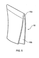
- leading edge strip component 16 After removing the PEEK sheet 10 from the moulding tools a leading edge strip component 16 remains, in which a portion 16a is smoothly solidified PEEK material, shaped to form a leading edge profile for an aerofoil, and a portion 16b remains as unmoulded drapable PEEK fabric.
- leading edge strip component 16 formed in accordance with the above process does not suffer from the problems associated with prior leading edge strip components made from PEEK fabric.
- due to the heat and pressure applied only to the extremity of the profile by the female moulding tool there is a smooth aerodynamically suitable surface at this point.
- the individual fibres are not exposed or disturbed the component retains its structural strength.
- the component 16 can then be easily placed in a resin transfer mould together with other materials/components which go to make the composite aerofoil, and the mould cavity is then injected and filled with resin, and cured. Resin flows into the interstices of the PEEK fabric and firmly bonds the leading edge fabric to the remaining layup of the composite aerofoil, with only a single bonding interface between the two.
- the PEEK fabric sheet 10 could be laid up and co-cured with a further strengthening fabric, such as a glass-and/or carbon-fibre fabric, before being locally moulded between the tools 12 and 14 as described above.
- a further strengthening fabric such as a glass-and/or carbon-fibre fabric
- the female moulding tool 14 can have several recesses 14a so as to accommodate several male moulding tools, and therefore leading edge component samples, in a single heat/pressure cycle.
- the depth of the recess 14a is of the order of 3mm, this could of course be varied to suit any particular profile being manufactured.
- the male tool need only be greater in depth than the recess 16a, even though a substantially larger male tool is depicted in Figures 2 and 4 .
- the male, and/or female tools could be prismatic in profile.
- the present invention provides a protective leading edge strip for an aerofoil, such as a blade or vane, which itself is easy to manufacture and which can also be readily introduced into a resin transfer mould.
Description
- The present invention relates to a method of manufacturing a protective leading edge strip for an aerofoil, such as a vane or blade. The invention is concerned particularly with a thermoplastic protective leading edge strip for a composite aerofoil vane.
- Within aero engines the leading edges of rotating and stationary aerofoils are often subjected to high-levels of erosion and impact loading. In particular fan blades and guide vanes endure harsh abrading environments including dust, sand, ice and water as well as occasional impacts from foreign bodies such as birds and other debris. Therefore the leading edges are often reinforced to make them more resilient to these environments.
- Conventionally, with metallic aerofoils the choice of metal may be sufficient to ensure the appropriate resistance to the harsh environment, or else a surface coating may be added to increase the resistance. However when considering composite technologies for fan blades and guide vanes, the composite material alone is not sufficient to withstand common levels of erosion or of impacts. Accordingly, if no extra protection is afforded to the composite blade at its leading edge, damage can propagate into the more structural parts of the aerofoil. Because of this, solutions have been proposed which include wrapping pieces of metal around the leading edges. This gives some protection of erosion and also give the possibility to dress back the leading edge. It also provides protection against impact from foreign bodies. Such an approach has been widely adopted in the field of aero engines.
- However, when using a metallic sheath on the leading edge of a composite aerofoil there is a need to apply separate surface treatments to both the sheath and the aerofoil and then bond the two together, which requires an extra production step. Furthermore, as the metallic sheaths are not generally structural components of the aerofoil they add weight without adding structural performance.
- An additional problem arises in that air worthiness regulations specify that any separate, or separable, component must be contained within the engine and must not endanger the aircraft or any ground equipment. Therefore it is necessary to take steps to contain any metallic leading edge which has the possibility to detach during high-energy impact events and become released. This is an especially important issue when used on rotating components such as fan blades. If a metallic leading edge is released from a fan blade it can become effectively a high-energy spear which, if not contained, can pose a serious threat to the aircraft. Containing metallic components of this kind can necessitate an increase in both the cost and the weight of the structures required to contain them.
- Currently some composite vanes have polyaryl ether ether ketone or polyetheretherketone (PEEK) thermoplastic erosion systems. The method of manufacture is to use both heat and pressure to form a PEEK sheet onto some glass fabric over a moulding tool to make a PEEK leading edge strip. The mould tool itself represents the first 30mm or so of the aerofoil, and thus defines the leading edge strip component itself. This method is described in
EP2111989 belonging to the present applicant. - Once this leading edge strip has been formed it is placed in the resin transfer mould (RTM) tool cavity along with the remaining materials that go to make up the composite vane, the other materials comprising mainly carbon fibre 3D woven preforms and 2D carbon fibre fabrics.
- Once layup is complete the mould cavity is injected and filled with resin which is then cured.
- During this process the resin that fills the mould micro-fills the glass fabric on the PEEK leading edge strip component. This interaction between the glass fabric and the resin provides a bond interface between the PEEK material and the vane itself.
- The manufacture of the PEEK leading edge strip is done in a compression mould tool. The glass fabric and PEEK sheet are laid over the tool and pressure is then applied to pre-clamp the tool and materials. The tool is then placed in an oven to ensure that the temperature is controlled to within very tight limits all over the surface of the tool. Once the PEEK has reached the melt temperature it partly flows into the glass fabric.
- Temperature and pressure variance across the tool surface directly affects the amount of PEEK that flows into the glass fabric and therefore can result in a variation in the strength of the bond between the two materials. The difference in the co-efficient of thermal expansion (CTE) of the materials also results in "spring-back" therefore affecting the form of the part, as well as causing inherent stress between the two materials which leads to potentially weak areas in the bond interface.
- An alternative previously considered method is to use just a PEEK fabric by itself. However when this is used the woven architecture of the fabric opens up as it goes around the edge, and this causes a rough surface which is not deemed aerodynamically acceptable. Furthermore because the fibres have opened up around the edge the material becomes structurally weakened in this crucial area.
- Embodiments of the present invention aim to provide a protective leading edge strip for a composite aerofoil in which at least some of the above-mentioned problems are addressed.
- The present invention is defined in the attached independent claim, to which reference should now be made. Further, preferred features may be found in the sub-claims appended thereto.
- According to the invention there is provided a method of forming a protective leading edge strip component for an aerofoil, the method comprising locating a portion of a thermoplastics fabric sheet between complementary male and female moulding tools and applying heat and pressure to the portion of fabric to cause the portion of fabric to take the shape of at least the tip of the male moulding tool.
- At least the tip of the male moulding tool may have the shape of a leading edge of an aerofoil.
- The female moulding tool preferably has a recess which is arranged in use to retain only the tip of the male moulding tool.
- Preferably heat is applied to the portion of fabric by the female moulding tool.
- The fabric may comprise a polyaryl ether ether ketone woven fabric.
- A preferred embodiment of the present invention will now be described by way of example only, with reference to the accompanying diagrammatic drawings, in which:
-
Figure 1 shows a portion of polyaryl ether ether ketone (PEEK) fabric; -
Figure 2 shows a male moulding tool for use in forming a protective leading edge strip in accordance with an embodiment of the present invention; -
Figure 3 shows a female moulding tool for use forming a protective leading edge strip in conjunction with the male tool ofFigure 2 , in accordance with an embodiment of the present invention; -
Figure 4 shows schematically the male and female moulding tools, respectively ofFigures 2 and3 , together in an operational configuration; and -
Figure 5 shows a leading edge component formed by the moulding tool ofFigures 2 to 4 . - An embodiment of the invention will now be described in greater detail with reference to the drawings.
- Firstly, as shown in
Figure 1 , asheet 10 of PEEK fabric, woven in two dimensions, is taken. Turning toFigure 2 , thesheet 10 is draped over amale moulding tool 12, the shape of which represents the shape of the leading edge of an aerofoil for which a leading edge strip component is to be made, in accordance with the invention. -
Figure 3 shows part of afemale moulding tool 14 generally of trapezoidal prism shape, which includes a shallowelongate recess 14a shaped to complement the tip of themale tool 12. The depth of therecess 14a is arranged so as to be able to accommodate only the very edge of the aerofoil profile of themale tool 12, which is in this case approximately the first 3mm of themale tool 12. - The assembled male 12 and female 14 moulding tools are shown in
Figure 4 . Heat is applied to thefemale tool 14 by an electric current via electrodes (not shown) and thefemale tool 14 is pressed against themale tool 12. The applied heat and pressure has the effect of melting and smoothing the portion of thePEEK sheet 10 that is gripped between themoulding tools - After removing the
PEEK sheet 10 from the moulding tools a leadingedge strip component 16 remains, in which aportion 16a is smoothly solidified PEEK material, shaped to form a leading edge profile for an aerofoil, and aportion 16b remains as unmoulded drapable PEEK fabric. - The leading
edge strip component 16 formed in accordance with the above process does not suffer from the problems associated with prior leading edge strip components made from PEEK fabric. In particular, due to the heat and pressure applied only to the extremity of the profile by the female moulding tool, there is a smooth aerodynamically suitable surface at this point. Furthermore, since the individual fibres are not exposed or disturbed the component retains its structural strength. - Due at least in part to the ready drapability of the
portion 16b thecomponent 16 can then be easily placed in a resin transfer mould together with other materials/components which go to make the composite aerofoil, and the mould cavity is then injected and filled with resin, and cured. Resin flows into the interstices of the PEEK fabric and firmly bonds the leading edge fabric to the remaining layup of the composite aerofoil, with only a single bonding interface between the two. - As an alternative, the PEEK
fabric sheet 10 could be laid up and co-cured with a further strengthening fabric, such as a glass-and/or carbon-fibre fabric, before being locally moulded between thetools - Due to the small surface area of contact between the male and female moulding tools only a very small tool surface area needs be thermally controlled, and only a relatively small tool mass is required. The relatively small surface area needed for the process also allows for an easy increase in applied pressure if needed. Further, the
female moulding tool 14 can haveseveral recesses 14a so as to accommodate several male moulding tools, and therefore leading edge component samples, in a single heat/pressure cycle. - Whilst in the above-described embodiment the depth of the
recess 14a is of the order of 3mm, this could of course be varied to suit any particular profile being manufactured. In its most basic form the male tool need only be greater in depth than therecess 16a, even though a substantially larger male tool is depicted inFigures 2 and4 . The male, and/or female tools could be prismatic in profile. - The present invention provides a protective leading edge strip for an aerofoil, such as a blade or vane, which itself is easy to manufacture and which can also be readily introduced into a resin transfer mould.
Claims (5)
- A method of forming a protective leading edge strip component (16) for an aerofoil, characterised in that the method comprises locating a portion (16a) of a thermoplastics fabric sheet between complementary male (12) and female (14) moulding tools and applying heat and pressure to the portion of fabric to cause the portion (16a) of fabric to take the shape of at least the tip of the male moulding tool.
- A method according to claim 1, wherein at least the tip the male moulding tool has the shape of a leading edge of an aerofoil.
- A method according to claim 1 or 2, wherein the female moulding tool has a recess which is arranged in use to retain only the tip of the male moulding tool and the portion of fabric therebetween.
- A method according to any of claims 1 to 3, wherein heat is applied to the portion of fabric by the female moulding tool.
- A method according to any of claims 1 to 4, wherein the fabric comprises a polyaryl ether ether ketone (PEEK) woven fabric.
Applications Claiming Priority (1)
| Application Number | Priority Date | Filing Date | Title |
|---|---|---|---|
| GB0913290A GB0913290D0 (en) | 2009-07-31 | 2009-07-31 | Method of manufacture of aerfoil leading edge strip |
Publications (2)
| Publication Number | Publication Date |
|---|---|
| EP2281679A1 EP2281679A1 (en) | 2011-02-09 |
| EP2281679B1 true EP2281679B1 (en) | 2014-03-05 |
Family
ID=41067098
Family Applications (1)
| Application Number | Title | Priority Date | Filing Date |
|---|---|---|---|
| EP20100167139 Active EP2281679B1 (en) | 2009-07-31 | 2010-06-24 | Method of manufacture of aerofoil leading edge strip |
Country Status (3)
| Country | Link |
|---|---|
| US (1) | US8979500B2 (en) |
| EP (1) | EP2281679B1 (en) |
| GB (1) | GB0913290D0 (en) |
Cited By (1)
| Publication number | Priority date | Publication date | Assignee | Title |
|---|---|---|---|---|
| CN109351753A (en) * | 2018-10-27 | 2019-02-19 | 河南教育学院 | The recovery method of glass fibre in a kind of discarded circuit board |
Families Citing this family (22)
| Publication number | Priority date | Publication date | Assignee | Title |
|---|---|---|---|---|
| US9354939B2 (en) * | 2010-05-28 | 2016-05-31 | Red Hat, Inc. | Generating customized build options for cloud deployment matching usage profile against cloud infrastructure options |
| GB201105712D0 (en) * | 2011-04-05 | 2011-05-18 | Rolls Royce Plc | A component having an erosion-resistant layer |
| CN111075511B (en) | 2013-05-29 | 2023-11-17 | 通用电气公司 | Composite airfoil metal patch |
| JP2017505873A (en) | 2014-01-16 | 2017-02-23 | ゼネラル・エレクトリック・カンパニイ | Stress relief shim at the base of the composite blade |
| US9745851B2 (en) | 2015-01-15 | 2017-08-29 | General Electric Company | Metal leading edge on composite blade airfoil and shank |
| US11149642B2 (en) | 2015-12-30 | 2021-10-19 | General Electric Company | System and method of reducing post-shutdown engine temperatures |
| US11053861B2 (en) | 2016-03-03 | 2021-07-06 | General Electric Company | Overspeed protection system and method |
| US10677259B2 (en) | 2016-05-06 | 2020-06-09 | General Electric Company | Apparatus and system for composite fan blade with fused metal lead edge |
| US10337405B2 (en) | 2016-05-17 | 2019-07-02 | General Electric Company | Method and system for bowed rotor start mitigation using rotor cooling |
| US10583933B2 (en) | 2016-10-03 | 2020-03-10 | General Electric Company | Method and apparatus for undercowl flow diversion cooling |
| US10947993B2 (en) | 2017-11-27 | 2021-03-16 | General Electric Company | Thermal gradient attenuation structure to mitigate rotor bow in turbine engine |
| FR3079445B1 (en) * | 2018-03-28 | 2020-04-24 | Safran | PROCESS FOR MANUFACTURING A BLADE OF COMPOSITE MATERIAL ON BOARD OF AN ADDED METAL ATTACK FOR GAS TURBINE |
| US11111815B2 (en) | 2018-10-16 | 2021-09-07 | General Electric Company | Frangible gas turbine engine airfoil with fusion cavities |
| US11434781B2 (en) | 2018-10-16 | 2022-09-06 | General Electric Company | Frangible gas turbine engine airfoil including an internal cavity |
| US10760428B2 (en) | 2018-10-16 | 2020-09-01 | General Electric Company | Frangible gas turbine engine airfoil |
| US10837286B2 (en) | 2018-10-16 | 2020-11-17 | General Electric Company | Frangible gas turbine engine airfoil with chord reduction |
| US10746045B2 (en) | 2018-10-16 | 2020-08-18 | General Electric Company | Frangible gas turbine engine airfoil including a retaining member |
| US11149558B2 (en) | 2018-10-16 | 2021-10-19 | General Electric Company | Frangible gas turbine engine airfoil with layup change |
| US11571863B2 (en) | 2021-05-24 | 2023-02-07 | Spirit Aerosystems, Inc. | Methods of fabricating multi-region U-shaped composite structures |
| US11674399B2 (en) | 2021-07-07 | 2023-06-13 | General Electric Company | Airfoil arrangement for a gas turbine engine utilizing a shape memory alloy |
| US11668317B2 (en) | 2021-07-09 | 2023-06-06 | General Electric Company | Airfoil arrangement for a gas turbine engine utilizing a shape memory alloy |
| US11879411B2 (en) | 2022-04-07 | 2024-01-23 | General Electric Company | System and method for mitigating bowed rotor in a gas turbine engine |
Family Cites Families (12)
| Publication number | Priority date | Publication date | Assignee | Title |
|---|---|---|---|---|
| GB2225742A (en) | 1988-12-09 | 1990-06-13 | Westland Helicopters | Moulding a fibre reinforced composite, into a hollow structure comprising outer and inner skins connected by ribs |
| GB8829993D0 (en) | 1988-12-22 | 1989-02-15 | Westland Helicopters | Method for forming components from fibre-reinforced thermoplastic materials |
| FR2699498B1 (en) * | 1992-12-23 | 1995-03-10 | Eurocopter France | Blade made of thermoplastic composite, in particular for a faired tail rotor of a helicopter, and its manufacturing process. |
| FR2756211B1 (en) * | 1996-11-26 | 1999-01-29 | Eurocopter France | PROCESS FOR PRODUCING A FLEXIBLE AND TORSIBLE COMPOSITE ELEMENT |
| GB0014113D0 (en) * | 2000-06-10 | 2000-08-02 | Gkn Westland Helicopters Ltd | Improvements in or relating to moulding |
| US6607358B2 (en) | 2002-01-08 | 2003-08-19 | General Electric Company | Multi-component hybrid turbine blade |
| US7575417B2 (en) * | 2003-09-05 | 2009-08-18 | General Electric Company | Reinforced fan blade |
| US20060081329A1 (en) * | 2004-10-14 | 2006-04-20 | Yuzo Kikuchi | Method of processing woven/knitted fabric and the like composed of thermal fusion bonding yarns |
| WO2006047374A1 (en) * | 2004-10-22 | 2006-05-04 | Dow Global Technologies Inc. | Improved microlayer structures and methods |
| US20080159870A1 (en) * | 2006-12-14 | 2008-07-03 | Hontek Corporation | Method and coating for protecting and repairing an airfoil surface using molded boots, sheet or tape |
| DE102006053985A1 (en) * | 2006-11-10 | 2008-05-15 | Rolls-Royce Deutschland Ltd & Co Kg | Process for producing a fiber composite component and fiber composite component produced thereafter |
| GB2459439A (en) * | 2008-04-21 | 2009-10-28 | Rolls Royce Plc | Producing an article containing a protective member by moulding |
-
2009
- 2009-07-31 GB GB0913290A patent/GB0913290D0/en not_active Ceased
-
2010
- 2010-06-24 US US12/822,465 patent/US8979500B2/en active Active
- 2010-06-24 EP EP20100167139 patent/EP2281679B1/en active Active
Cited By (1)
| Publication number | Priority date | Publication date | Assignee | Title |
|---|---|---|---|---|
| CN109351753A (en) * | 2018-10-27 | 2019-02-19 | 河南教育学院 | The recovery method of glass fibre in a kind of discarded circuit board |
Also Published As
| Publication number | Publication date |
|---|---|
| GB0913290D0 (en) | 2009-09-02 |
| US20110027096A1 (en) | 2011-02-03 |
| US8979500B2 (en) | 2015-03-17 |
| EP2281679A1 (en) | 2011-02-09 |
Similar Documents
| Publication | Publication Date | Title |
|---|---|---|
| EP2281679B1 (en) | Method of manufacture of aerofoil leading edge strip | |
| US7581932B2 (en) | Method of manufacturing a composite turbomachine blade, and a blade obtained by the method | |
| US8851421B2 (en) | Aerofoil with erosion resistant leading edge | |
| US20110194941A1 (en) | Co-cured sheath for composite blade | |
| EP3027385B1 (en) | Erosion resistant aerodynamic fairing | |
| CN111936303B (en) | Method of manufacturing a blade for a gas turbine engine with a fitted metal leading edge from a composite material | |
| US10899051B2 (en) | Method of fabricating a composite material blade having an integrated metal leading edge for a gas turbine aeroengine | |
| US9108331B2 (en) | Cutting of preforms prior to RTM injection by means of a water jet and cryonics | |
| US10259169B2 (en) | Method of fastening structural metal reinforcement on a portion of a gas turbine blade made of composite material, and an injection mold for performing such a method | |
| US20110070092A1 (en) | Hybrid component | |
| EP2253803B1 (en) | Composite aerofoil blade with wear-resistant tip and corresponding method | |
| US5843354A (en) | Method for compression molding a fan blade | |
| FR2953225A1 (en) | Composite component i.e. contoured preform, for forming e.g. low pressure compressor blade of turbojet engine of airplane, has leading edge comprising weft and reinforcing yarns that contain carbon and metal fibers, respectively | |
| US20220362856A1 (en) | Method for manufacturing a composite material vane with an attached metal leading edge | |
| US8318067B2 (en) | Resin transfer moulding process for an article containing a protective member | |
| US20150247411A1 (en) | Blade tip | |
| EP2508712A2 (en) | A component having an erosion-resistant layer | |
| US20200165919A1 (en) | Propeller blades | |
| US11401823B2 (en) | Aircraft turbomachine provided with an unducted propeller with blades having a composite-material insert bonded to their leading edges | |
| EP3007969A1 (en) | Manufacturing method and apparatus for stringer reinforced composite skin | |
| CN110065242B (en) | Manufacture of composite parts having both continuous and chopped fiber components | |
| GB2485758A (en) | Method of forming a composite component by machining a frangible separation line | |
| US20230311428A1 (en) | Method for manufacturing a composite part for a turbomachine | |
| US20230407754A1 (en) | Composite vane for an aircraft turbomachine and method for the manufacture thereof |
Legal Events
| Date | Code | Title | Description |
|---|---|---|---|
| PUAI | Public reference made under article 153(3) epc to a published international application that has entered the european phase |
Free format text: ORIGINAL CODE: 0009012 |
|
| AK | Designated contracting states |
Kind code of ref document: A1 Designated state(s): AL AT BE BG CH CY CZ DE DK EE ES FI FR GB GR HR HU IE IS IT LI LT LU LV MC MK MT NL NO PL PT RO SE SI SK SM TR |
|
| AX | Request for extension of the european patent |
Extension state: BA ME RS |
|
| 17P | Request for examination filed |
Effective date: 20110805 |
|
| 17Q | First examination report despatched |
Effective date: 20120131 |
|
| GRAP | Despatch of communication of intention to grant a patent |
Free format text: ORIGINAL CODE: EPIDOSNIGR1 |
|
| INTG | Intention to grant announced |
Effective date: 20131127 |
|
| GRAS | Grant fee paid |
Free format text: ORIGINAL CODE: EPIDOSNIGR3 |
|
| GRAA | (expected) grant |
Free format text: ORIGINAL CODE: 0009210 |
|
| AK | Designated contracting states |
Kind code of ref document: B1 Designated state(s): AL AT BE BG CH CY CZ DE DK EE ES FI FR GB GR HR HU IE IS IT LI LT LU LV MC MK MT NL NO PL PT RO SE SI SK SM TR |
|
| REG | Reference to a national code |
Ref country code: GB Ref legal event code: FG4D |
|
| REG | Reference to a national code |
Ref country code: CH Ref legal event code: EP |
|
| REG | Reference to a national code |
Ref country code: AT Ref legal event code: REF Ref document number: 654529 Country of ref document: AT Kind code of ref document: T Effective date: 20140315 |
|
| REG | Reference to a national code |
Ref country code: IE Ref legal event code: FG4D |
|
| REG | Reference to a national code |
Ref country code: DE Ref legal event code: R096 Ref document number: 602010013905 Country of ref document: DE Effective date: 20140417 |
|
| REG | Reference to a national code |
Ref country code: AT Ref legal event code: MK05 Ref document number: 654529 Country of ref document: AT Kind code of ref document: T Effective date: 20140305 |
|
| REG | Reference to a national code |
Ref country code: NL Ref legal event code: VDEP Effective date: 20140305 |
|
| PG25 | Lapsed in a contracting state [announced via postgrant information from national office to epo] |
Ref country code: NO Free format text: LAPSE BECAUSE OF FAILURE TO SUBMIT A TRANSLATION OF THE DESCRIPTION OR TO PAY THE FEE WITHIN THE PRESCRIBED TIME-LIMIT Effective date: 20140605 Ref country code: LT Free format text: LAPSE BECAUSE OF FAILURE TO SUBMIT A TRANSLATION OF THE DESCRIPTION OR TO PAY THE FEE WITHIN THE PRESCRIBED TIME-LIMIT Effective date: 20140305 |
|
| REG | Reference to a national code |
Ref country code: LT Ref legal event code: MG4D |
|
| PG25 | Lapsed in a contracting state [announced via postgrant information from national office to epo] |
Ref country code: FI Free format text: LAPSE BECAUSE OF FAILURE TO SUBMIT A TRANSLATION OF THE DESCRIPTION OR TO PAY THE FEE WITHIN THE PRESCRIBED TIME-LIMIT Effective date: 20140305 Ref country code: CY Free format text: LAPSE BECAUSE OF FAILURE TO SUBMIT A TRANSLATION OF THE DESCRIPTION OR TO PAY THE FEE WITHIN THE PRESCRIBED TIME-LIMIT Effective date: 20140305 Ref country code: SE Free format text: LAPSE BECAUSE OF FAILURE TO SUBMIT A TRANSLATION OF THE DESCRIPTION OR TO PAY THE FEE WITHIN THE PRESCRIBED TIME-LIMIT Effective date: 20140305 Ref country code: AT Free format text: LAPSE BECAUSE OF FAILURE TO SUBMIT A TRANSLATION OF THE DESCRIPTION OR TO PAY THE FEE WITHIN THE PRESCRIBED TIME-LIMIT Effective date: 20140305 |
|
| PG25 | Lapsed in a contracting state [announced via postgrant information from national office to epo] |
Ref country code: LV Free format text: LAPSE BECAUSE OF FAILURE TO SUBMIT A TRANSLATION OF THE DESCRIPTION OR TO PAY THE FEE WITHIN THE PRESCRIBED TIME-LIMIT Effective date: 20140305 Ref country code: HR Free format text: LAPSE BECAUSE OF FAILURE TO SUBMIT A TRANSLATION OF THE DESCRIPTION OR TO PAY THE FEE WITHIN THE PRESCRIBED TIME-LIMIT Effective date: 20140305 |
|
| PG25 | Lapsed in a contracting state [announced via postgrant information from national office to epo] |
Ref country code: NL Free format text: LAPSE BECAUSE OF FAILURE TO SUBMIT A TRANSLATION OF THE DESCRIPTION OR TO PAY THE FEE WITHIN THE PRESCRIBED TIME-LIMIT Effective date: 20140305 Ref country code: RO Free format text: LAPSE BECAUSE OF FAILURE TO SUBMIT A TRANSLATION OF THE DESCRIPTION OR TO PAY THE FEE WITHIN THE PRESCRIBED TIME-LIMIT Effective date: 20140305 Ref country code: CZ Free format text: LAPSE BECAUSE OF FAILURE TO SUBMIT A TRANSLATION OF THE DESCRIPTION OR TO PAY THE FEE WITHIN THE PRESCRIBED TIME-LIMIT Effective date: 20140305 Ref country code: EE Free format text: LAPSE BECAUSE OF FAILURE TO SUBMIT A TRANSLATION OF THE DESCRIPTION OR TO PAY THE FEE WITHIN THE PRESCRIBED TIME-LIMIT Effective date: 20140305 Ref country code: BE Free format text: LAPSE BECAUSE OF FAILURE TO SUBMIT A TRANSLATION OF THE DESCRIPTION OR TO PAY THE FEE WITHIN THE PRESCRIBED TIME-LIMIT Effective date: 20140305 Ref country code: BG Free format text: LAPSE BECAUSE OF FAILURE TO SUBMIT A TRANSLATION OF THE DESCRIPTION OR TO PAY THE FEE WITHIN THE PRESCRIBED TIME-LIMIT Effective date: 20140605 Ref country code: IS Free format text: LAPSE BECAUSE OF FAILURE TO SUBMIT A TRANSLATION OF THE DESCRIPTION OR TO PAY THE FEE WITHIN THE PRESCRIBED TIME-LIMIT Effective date: 20140705 |
|
| PG25 | Lapsed in a contracting state [announced via postgrant information from national office to epo] |
Ref country code: SK Free format text: LAPSE BECAUSE OF FAILURE TO SUBMIT A TRANSLATION OF THE DESCRIPTION OR TO PAY THE FEE WITHIN THE PRESCRIBED TIME-LIMIT Effective date: 20140305 Ref country code: ES Free format text: LAPSE BECAUSE OF FAILURE TO SUBMIT A TRANSLATION OF THE DESCRIPTION OR TO PAY THE FEE WITHIN THE PRESCRIBED TIME-LIMIT Effective date: 20140305 Ref country code: PL Free format text: LAPSE BECAUSE OF FAILURE TO SUBMIT A TRANSLATION OF THE DESCRIPTION OR TO PAY THE FEE WITHIN THE PRESCRIBED TIME-LIMIT Effective date: 20140305 |
|
| REG | Reference to a national code |
Ref country code: DE Ref legal event code: R097 Ref document number: 602010013905 Country of ref document: DE |
|
| PG25 | Lapsed in a contracting state [announced via postgrant information from national office to epo] |
Ref country code: PT Free format text: LAPSE BECAUSE OF FAILURE TO SUBMIT A TRANSLATION OF THE DESCRIPTION OR TO PAY THE FEE WITHIN THE PRESCRIBED TIME-LIMIT Effective date: 20140707 |
|
| PLBE | No opposition filed within time limit |
Free format text: ORIGINAL CODE: 0009261 |
|
| STAA | Information on the status of an ep patent application or granted ep patent |
Free format text: STATUS: NO OPPOSITION FILED WITHIN TIME LIMIT |
|
| PG25 | Lapsed in a contracting state [announced via postgrant information from national office to epo] |
Ref country code: LU Free format text: LAPSE BECAUSE OF FAILURE TO SUBMIT A TRANSLATION OF THE DESCRIPTION OR TO PAY THE FEE WITHIN THE PRESCRIBED TIME-LIMIT Effective date: 20140624 Ref country code: MC Free format text: LAPSE BECAUSE OF FAILURE TO SUBMIT A TRANSLATION OF THE DESCRIPTION OR TO PAY THE FEE WITHIN THE PRESCRIBED TIME-LIMIT Effective date: 20140305 Ref country code: DK Free format text: LAPSE BECAUSE OF FAILURE TO SUBMIT A TRANSLATION OF THE DESCRIPTION OR TO PAY THE FEE WITHIN THE PRESCRIBED TIME-LIMIT Effective date: 20140305 |
|
| REG | Reference to a national code |
Ref country code: CH Ref legal event code: PL |
|
| 26N | No opposition filed |
Effective date: 20141208 |
|
| REG | Reference to a national code |
Ref country code: DE Ref legal event code: R097 Ref document number: 602010013905 Country of ref document: DE Effective date: 20141208 |
|
| REG | Reference to a national code |
Ref country code: IE Ref legal event code: MM4A |
|
| PG25 | Lapsed in a contracting state [announced via postgrant information from national office to epo] |
Ref country code: IT Free format text: LAPSE BECAUSE OF FAILURE TO SUBMIT A TRANSLATION OF THE DESCRIPTION OR TO PAY THE FEE WITHIN THE PRESCRIBED TIME-LIMIT Effective date: 20140305 |
|
| PG25 | Lapsed in a contracting state [announced via postgrant information from national office to epo] |
Ref country code: CH Free format text: LAPSE BECAUSE OF NON-PAYMENT OF DUE FEES Effective date: 20140630 Ref country code: IE Free format text: LAPSE BECAUSE OF NON-PAYMENT OF DUE FEES Effective date: 20140624 Ref country code: LI Free format text: LAPSE BECAUSE OF NON-PAYMENT OF DUE FEES Effective date: 20140630 |
|
| PG25 | Lapsed in a contracting state [announced via postgrant information from national office to epo] |
Ref country code: SI Free format text: LAPSE BECAUSE OF FAILURE TO SUBMIT A TRANSLATION OF THE DESCRIPTION OR TO PAY THE FEE WITHIN THE PRESCRIBED TIME-LIMIT Effective date: 20140305 |
|
| REG | Reference to a national code |
Ref country code: FR Ref legal event code: PLFP Year of fee payment: 6 |
|
| PG25 | Lapsed in a contracting state [announced via postgrant information from national office to epo] |
Ref country code: MT Free format text: LAPSE BECAUSE OF FAILURE TO SUBMIT A TRANSLATION OF THE DESCRIPTION OR TO PAY THE FEE WITHIN THE PRESCRIBED TIME-LIMIT Effective date: 20140305 |
|
| PG25 | Lapsed in a contracting state [announced via postgrant information from national office to epo] |
Ref country code: SM Free format text: LAPSE BECAUSE OF FAILURE TO SUBMIT A TRANSLATION OF THE DESCRIPTION OR TO PAY THE FEE WITHIN THE PRESCRIBED TIME-LIMIT Effective date: 20140305 |
|
| REG | Reference to a national code |
Ref country code: FR Ref legal event code: PLFP Year of fee payment: 7 |
|
| PG25 | Lapsed in a contracting state [announced via postgrant information from national office to epo] |
Ref country code: GR Free format text: LAPSE BECAUSE OF FAILURE TO SUBMIT A TRANSLATION OF THE DESCRIPTION OR TO PAY THE FEE WITHIN THE PRESCRIBED TIME-LIMIT Effective date: 20140606 |
|
| PG25 | Lapsed in a contracting state [announced via postgrant information from national office to epo] |
Ref country code: HU Free format text: LAPSE BECAUSE OF FAILURE TO SUBMIT A TRANSLATION OF THE DESCRIPTION OR TO PAY THE FEE WITHIN THE PRESCRIBED TIME-LIMIT; INVALID AB INITIO Effective date: 20100624 Ref country code: TR Free format text: LAPSE BECAUSE OF FAILURE TO SUBMIT A TRANSLATION OF THE DESCRIPTION OR TO PAY THE FEE WITHIN THE PRESCRIBED TIME-LIMIT Effective date: 20140305 |
|
| REG | Reference to a national code |
Ref country code: FR Ref legal event code: PLFP Year of fee payment: 8 |
|
| REG | Reference to a national code |
Ref country code: FR Ref legal event code: PLFP Year of fee payment: 9 |
|
| PG25 | Lapsed in a contracting state [announced via postgrant information from national office to epo] |
Ref country code: MK Free format text: LAPSE BECAUSE OF FAILURE TO SUBMIT A TRANSLATION OF THE DESCRIPTION OR TO PAY THE FEE WITHIN THE PRESCRIBED TIME-LIMIT Effective date: 20140305 |
|
| PG25 | Lapsed in a contracting state [announced via postgrant information from national office to epo] |
Ref country code: AL Free format text: LAPSE BECAUSE OF FAILURE TO SUBMIT A TRANSLATION OF THE DESCRIPTION OR TO PAY THE FEE WITHIN THE PRESCRIBED TIME-LIMIT Effective date: 20140305 |
|
| P01 | Opt-out of the competence of the unified patent court (upc) registered |
Effective date: 20230528 |
|
| PGFP | Annual fee paid to national office [announced via postgrant information from national office to epo] |
Ref country code: FR Payment date: 20230622 Year of fee payment: 14 Ref country code: DE Payment date: 20230627 Year of fee payment: 14 |
|
| PGFP | Annual fee paid to national office [announced via postgrant information from national office to epo] |
Ref country code: GB Payment date: 20230620 Year of fee payment: 14 |