EP2281651A2 - Motor-driven handheld circular saw - Google Patents
Motor-driven handheld circular saw Download PDFInfo
- Publication number
- EP2281651A2 EP2281651A2 EP10007607A EP10007607A EP2281651A2 EP 2281651 A2 EP2281651 A2 EP 2281651A2 EP 10007607 A EP10007607 A EP 10007607A EP 10007607 A EP10007607 A EP 10007607A EP 2281651 A2 EP2281651 A2 EP 2281651A2
- Authority
- EP
- European Patent Office
- Prior art keywords
- circular saw
- damping element
- saw according
- saw
- gear
- Prior art date
- Legal status (The legal status is an assumption and is not a legal conclusion. Google has not performed a legal analysis and makes no representation as to the accuracy of the status listed.)
- Withdrawn
Links
Images


Classifications
-
- B—PERFORMING OPERATIONS; TRANSPORTING
- B23—MACHINE TOOLS; METAL-WORKING NOT OTHERWISE PROVIDED FOR
- B23D—PLANING; SLOTTING; SHEARING; BROACHING; SAWING; FILING; SCRAPING; LIKE OPERATIONS FOR WORKING METAL BY REMOVING MATERIAL, NOT OTHERWISE PROVIDED FOR
- B23D47/00—Sawing machines or sawing devices working with circular saw blades, characterised only by constructional features of particular parts
- B23D47/005—Vibration-damping
Definitions
- the invention relates to a motor-driven circular saw, in particular dip circular saw, with an electric motor with an armature shaft receiving motor housing part and a saw shaft and a circular saw blade receiving gear or statgegepurteil, which are directly or indirectly mounted against each other, wherein the circular saw blade against a clamping flange at the saw shaft rotatably mounted.
- the present invention has for its object to provide a motor-driven circular saw, which can be produced in an economical manner and yet characterized by smoothness and a long service life.
- the high speed driven circular saw blade has a high resonance capacity for the introduction of acoustic and tactile perceivable vibrations on the housing parts and also promotes the absorption and emission of vibrations arising in the transmission area.
- the inventive interposition of the damping element between said components and preferably both between the motor housing part and gear or Supergegepuruseteil and between clamping flange and a gradation of the saw shaft or between clamping flange and saw blade can be a decoupling of the resonant capacitance having housing parts or the housing parts of the saw blade reach , This can be realized in an economical way a high level of smoothness in the portable circular saw, while a desired game in the field of transmission components can be maintained.
- these transmission components comprise a drive pinion provided on the armature shaft, which extends out of the motor housing part and extends into the gear or saw housing part and is in drive connection there with the saw shaft, typically via a spur toothing in the region of the saw shaft.
- bearing components typically roller bearings, provided for the saw shaft and preferably also for the armature shaft in the gear or statgegephinuseteil in correspondingly shaped bearing receiving areas.
- the sheet-like resiliently deformable cushioning element may be made of cork-based, cellulose-based, felt or leather, or plastic-based, rubber-based or elastomer-based. It is according to the invention designed so that it is yieldingly deformable and preferably at least in the not yet installed state has certain elastic properties, that is, a certain resilience. Even if such a damping element is compressed in the installed state in such a way that the resiliency of the compressed and compressed material can only be determined to a slight extent during the subsequent release, it nevertheless turns out that the damping element has a high degree of effectiveness between the components mentioned.
- the damping element is made of plastic, elastomer or rubber based. It comprises in a particularly preferred manner a foamed elastomer or foamed rubber. Artificial foam, polyurethane foam, cellular rubber, sponge rubber or silicone foam have proved to be particularly advantageous materials.
- the damping element may advantageously include an EPDM base (ethylene propylene diene polymer) or SBR base (styrene-butadiene polymer) or NBR-based (acrylonitrile-butadiene polymer).
- EPDM base ethylene propylene diene polymer
- SBR base styrene-butadiene polymer
- NBR-based acrylonitrile-butadiene polymer
- the damping element has a compression set between 0-40%, in particular between 0-30%, in particular between 0-20%, in particular between 0-10%.
- the compression set refers to the permanent deformation after a uniform load; it is determined according to DIN 53 517 or DIN ISO 815 or ASTM D 395.
- the damping element is formed areally. It advantageously comprises a thickness of 1.0 to 5 mm, in particular of 1.5 to 4 mm and more particularly of 1.5 to 3 mm.
- the damping element is preferably produced as a molded part, in particular as a stamped part or cut part, from a planar material present as a flat material.
- the damping element is advantageously formed annularly closed and may have the basic shape of a circumferentially closed flat gasket element.
- the invention proves to be particularly advantageous in circular saws, in which the motor housing part is made of plastic and the gear or SAgegepurteil made of metal, in particular of light metal, such as aluminum, magnesium, and in particular as a metallic die-cast part is formed.
- an opening of the motor housing part is covered on its side facing the gear or statgegephasephaseuseteil side of a cover part with an opening for the passage of the armature shaft, and the gear or statgegephaseuseteil below Intermediate arrangement of the damping element abuts against the cover part.
- the said cover part is advantageously a so-called air guide disc, which guides a cooling air flow and suction air flow for the removal of sawdust in terms of flow.
- the circular saw has a pivotable protective cover which surrounds the circular saw blade and in the execution of a saw cut the circular saw blade against a spring preload releases automatically or manually in a release position is pivotal. If the pivotable protective hood is manually pivotable into a release position and preferably can be locked there, then this proves to be advantageous for the formation of plunge cuts.
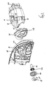
- FIG. 1 shows a generally designated by the reference numeral 2 electric motor driven circular saw, which is designed as a dip circular saw. It comprises a motor housing part 4, which has the electric motor and to which other components such as bow handle 6 and knob handle 8 are attached. Further, the circular saw 2 comprises a gear or statgegephinuseteil 10, of which in the Figures 2 and 3 a motor housing part 4 facing half-shell is shown.
- the gear or statorteil supports a saw shaft 12, rotatably on the clamping flange 14 ( FIG. 2 ), against which a circular saw blade 16 by means of a screw 18 with integrally formed clamping flange 20 is rotatably mounted.
- the gear or statorteil 10 is fastened in a manner to be described in more detail against the motor housing part 4, and the unit thus formed is pivotable relative to a parallel to the saw shaft 12 axis of rotation 22 relative to a base portion 24 of the circular saw 2 for performing dive cuts, in the direction of Double arrow 26.
- a side stop means 28 is shown.
- a circular saw blade 16 extending and releasing protective hood is designated by reference numeral 30.
- the guard 30 is biased in the closing direction (arrow 32) and can be pivoted against the closing direction in the execution of a saw cut automatically in a saw blade increasingly releasing position.
- the motor housing part 4 is cup-shaped and carries on its side facing away from the gear or statgegephasephaseuseteil 10 side a fan 34. He is on his the gear or statgegephasephaseuseteil 10th facing side of a cover part 36 closed, which forms a Heilleitemia.
- the cover part 36 is exemplarily recessed in the region of threaded openings 38 in the cup-shaped part. Both parts are preferably made of sprayable plastic. How very good FIG.
- FIG. 2 a scribed structure 42, which support the stability of the gear or shegegephins, especially in areas where bearing elements, not shown, are arranged, especially with regard to their dimensional accuracy and torsional rigidity in operation.
- a first damping element 42 (FIG. FIG. 3 ) and between the saw shaft 12 and clamping flange 14 for the circular saw blade 16, a second damping element 44 is provided.
- Both damping elements 42, 44 are made of a resiliently deformable material of the type described above.
- the first damping element 42 acts like an annular closed flat gasket.
- the second damping element 44 is formed circular disk-shaped. It would also be conceivable that it has approximately the surface of the clamping flange 14 and is arranged between circular saw blade 16 and clamping flange 14.
- the first damping element 42 is between an end face 46, facing the motor housing part 4, of the block-like housing region 40 of the gear or saw housing part 10 and an end face 48 facing it the lid part 36 is arranged.
- screws not shown are used, which are passed from an inner side of the block-like portion 40 through openings 50 in the first damping element 42 and screwed into said threaded openings 38 in the motor housing part 4.
- a preferably uniform compressive force is exerted on the first damping element 42, and it is thereby compressed in the region of the mutually abutting end faces 46 and 48. Nevertheless, it can develop its dampening effect.
Abstract
Description
Die Erfindung betrifft eine motorisch angetriebene Handkreissäge, insbesondere Tauchkreissäge, mit einem einen Elektromotor mit einer Ankerwelle aufnehmenden Motorgehäuseteil und einem eine Sägewelle und ein Kreissägeblatt aufnehmenden Getriebe- oder Sägegehäuseteil, die mittelbar oder unmittelbar gegeneinander montiert sind, wobei das Kreissägeblatt gegen einen Spannflansch bei der Sägewelle drehfest montierbar ist.The invention relates to a motor-driven circular saw, in particular dip circular saw, with an electric motor with an armature shaft receiving motor housing part and a saw shaft and a circular saw blade receiving gear or Sägegehäuseteil, which are directly or indirectly mounted against each other, wherein the circular saw blade against a clamping flange at the saw shaft rotatably mounted.
Bei Handkreissägen und insbesondere bei Tauchkreissägen, bei denen Motor- und Sägegehäuseteil um eine parallel zur Sägewelle verlaufende Achse gegenüber einer auf der zu bearbeitenden Fläche aufliegenden Basis verschwenkbar sind, stellt sich aufgrund des großen Trägheitsmoments und des notwendigerweise vorzusehenden Spiels bei den Getriebekomponenten stets die Aufgabe, die Laufruhe zu beherrschen und hohe Standzeiten zu erreichen. Man versuchte bislang, dies durch hochgenaue Fertigung der Gehäuseteile und der in den Gehäuseteilen vorgesehenen Lagerkomponenten und Getriebekomponenten zu verbessern.In portable circular saws, and in particular circular plunge saws, in which motor and Sägegehäuseteil are pivotable about an axis parallel to the saw shaft against a resting on the surface to be machined base, arises due to the large moment of inertia and the necessarily be provided game in the transmission components always the task to control the smoothness and to achieve long service life. Attempts have been made so far to improve this by highly accurate manufacture of the housing parts and provided in the housing parts bearing components and transmission components.
Der vorliegenden Erfindung liegt die Aufgabe zugrunde, eine motorisch angetriebene Handkreissäge bereitzustellen, die auf wirtschaftliche Weise herstellbar ist und sich dennoch durch Laufruhe und eine hohe Standzeit auszeichnet.The present invention has for its object to provide a motor-driven circular saw, which can be produced in an economical manner and yet characterized by smoothness and a long service life.
Diese Aufgabe wird bei einer Handkreissäge der genannten Art erfindungsgemäß dadurch gelöst, dass zwischen Motorgehäuseteil und Getriebe- oder Sägegehäuseteil und/oder zwischen Spannflansch und einer Abstufung der Sägewelle oder zwischen Spannflansch und Kreissägeblatt ein flächenhaft erstrecktes nachgiebig verformbares Dämpfungselement vorgesehen ist.This object is achieved in a circular saw of the type mentioned in the present invention that between the motor housing part and gear or Sägegehäuseteil and / or between clamping flange and a gradation of the saw shaft or between clamping flange and circular saw blade a planar extending yielding deformable damping element is provided.
Es wurde überraschenderweise festgestellt, dass sich bei einer Handkreissäge der genannten Art eine höhere Laufruhe erreichen lässt, wenn man von dem seither praktizierten Prinzip der harten Verbindung der Gehäuseteile gegeneinander und/oder des Sägeblatts gegen die Sägewelle Abstand nimmt und stattdessen ein nachgiebig verformbares Dämpfungselement zwischenordnet. Es wurde mit der vorliegenden Erfindung nämlich festgestellt, dass das mit hohen Drehzahlen angetriebene Kreissägeblatt eine hohe Resonanzkapazität für die Einleitung von akustisch und taktil wahrnehmbaren Schwingungen auf die Gehäuseteile darstellt und auch die Aufnahme und Aussendung von im Getriebebereich entstehenden Schwingungen begünstigt. Durch die erfindungsgemäße Zwischenordnung des Dämpfungselements zwischen den genannten Komponenten und vorzugsweise sowohl zwischen Motorgehäuseteil und Getriebe- oder Sägegehäuseteil und zwischen Spannflansch und einer Abstufung der Sägewelle oder zwischen Spannflansch und Sägeblatt lässt sich eine Entkopplung der Resonanzkapazität aufweisenden Gehäuseteile voneinander bzw. der Gehäuseteile von dem Sägeblatt erreichen. Hiermit kann auf wirtschaftliche Weise eine hohe Laufruhe bei der Handkreissäge realisiert werden, wobei gleichzeitig ein erwünschtes Spiel im Bereich der Getriebekomponenten beibehalten werden kann. Es hat sich gezeigt, dass die erhebliche Geräuschentwicklung beim Anfahren der Handkreissäge im noch unbelasteten Zustand (Leerlauf) infolge des trägheitsbedingten Überholeffekts der das Sägeblatt aufweisenden Abtriebskomponenten deutlich reduziert werden kann, und zwar ohne dass ein erhöhter Aufwand im Bereich der Genauigkeit der Ausbildung, der Anordnung und des Zusammenwirkens der Getriebekomponenten betrieben werden müsste.It has surprisingly been found that can be achieved in a circular saw of the type mentioned a higher smoothness, if one takes distance from the principle practiced since the hard connection of the housing parts against each other and / or the saw blade against the saw shaft and instead interposes a resiliently deformable damping element. Namely, it has been found with the present invention that the high speed driven circular saw blade has a high resonance capacity for the introduction of acoustic and tactile perceivable vibrations on the housing parts and also promotes the absorption and emission of vibrations arising in the transmission area. The inventive interposition of the damping element between said components and preferably both between the motor housing part and gear or Sägegehäuseteil and between clamping flange and a gradation of the saw shaft or between clamping flange and saw blade can be a decoupling of the resonant capacitance having housing parts or the housing parts of the saw blade reach , This can be realized in an economical way a high level of smoothness in the portable circular saw, while a desired game in the field of transmission components can be maintained. It has been shown that the considerable noise when starting the portable circular saw in the still unloaded state (idle) due to the inertial overtaking effect of the saw blade having output components can be significantly reduced, without an increased effort in the field of accuracy of training, the arrangement and the interaction of the transmission components would have to be operated.
Typischerweise umfassen diese Getriebekomponenten ein auf der Ankerwelle vorgesehenes Antriebsritzel, welches sich aus dem Motorgehäuseteil herauserstreckt und in den Getriebe- oder Sägegehäuseteil hineinerstreckt und dort mit der Sägewelle, typischerweise über eine Stirnverzahnung im Bereich der Sägewelle, in Antriebsverbindung steht. Hierfür sind Lagerkomponenten, typischerweise Wälzlager, für die Sägewelle und vorzugsweise auch für die Ankerwelle in dem Getriebe- oder Sägegehäuseteil in entsprechend geformten Lageraufnahmebereichen vorgesehen.Typically, these transmission components comprise a drive pinion provided on the armature shaft, which extends out of the motor housing part and extends into the gear or saw housing part and is in drive connection there with the saw shaft, typically via a spur toothing in the region of the saw shaft. For this purpose, bearing components, typically roller bearings, provided for the saw shaft and preferably also for the armature shaft in the gear or Sägegehäuseteil in correspondingly shaped bearing receiving areas.
Es hat sich herausgestellt, dass bei Anordnung des Dämpfungselements zwischen dem Motorgehäuseteil und dem Getriebe- oder Sägegehäuseteil eine Entkopplung der beiden Gehäuseteile voneinander erreichbar ist, die wesentlich zur Erhöhung der Laufruhe beiträgt, was nicht ohne weiteres zu erwarten war.It has been found that in the arrangement of the damping element between the motor housing part and the gear or Sägegehäuseteil a decoupling of the two housing parts is reached from each other, which contributes significantly to increase the smoothness, which was not readily expected.
Nach einer ersten Ausführungsform der Erfindung kann das flächenhafte nachgiebig verformbare Dämpfungselement auf Korkbasis, Zellulosebasis, aus Filz oder Leder, oder auf Kunststoffbasis, Gummibasis oder Elastomerbasis hergestellt sein. Es ist erfindungsgemäß so ausgebildet, dass es nachgiebig verformbar ist und zumindest im noch nicht verbauten Zustand vorzugsweise gewisse elastische Eigenschaften, also ein gewisses Rückstellvermögen aufweist. Auch wenn ein solches Dämpfungselement im verbauten Zustand derart komprimiert wird, dass beim anschließenden Lösen das Rückstellvermögen des komprimierten und verpressten Materials nur noch in geringem Maße feststellbar ist, so zeigt es sich doch, dass das Dämpfungselement zwischen den genannten Komponenten eine hohe Wirksamkeit aufweist.According to a first embodiment of the invention, the sheet-like resiliently deformable cushioning element may be made of cork-based, cellulose-based, felt or leather, or plastic-based, rubber-based or elastomer-based. It is according to the invention designed so that it is yieldingly deformable and preferably at least in the not yet installed state has certain elastic properties, that is, a certain resilience. Even if such a damping element is compressed in the installed state in such a way that the resiliency of the compressed and compressed material can only be determined to a slight extent during the subsequent release, it nevertheless turns out that the damping element has a high degree of effectiveness between the components mentioned.
In bevorzugter Weise ist das Dämpfungselement auf Kunststoffbasis, Elastomerbasis oder Gummibasis hergestellt. Es umfasst dabei in besonders bevorzugter Weise ein geschäumtes Elastomer oder geschäumten Gummi. Als besonders vorteilhafte Materialien haben sich Kunstschaumstoff, Polyurethanschaum, Zellkautschuk, Moosgummi oder Silikonschaum erwiesen.Preferably, the damping element is made of plastic, elastomer or rubber based. It comprises in a particularly preferred manner a foamed elastomer or foamed rubber. Artificial foam, polyurethane foam, cellular rubber, sponge rubber or silicone foam have proved to be particularly advantageous materials.
Das Dämpfungselement kann dabei in vorteilhafter Weise eine EPDM-Basis (Ethylen Propylen Dien-Polymerisat) oder SBR-Basis (Styrol-Butadien-Polymerisat) oder NBR-Basis (Acrylnitril-Butadien-Polymerisat) umfassen.The damping element may advantageously include an EPDM base (ethylene propylene diene polymer) or SBR base (styrene-butadiene polymer) or NBR-based (acrylonitrile-butadiene polymer).
Es erweist sich als vorteilhaft, wenn das Dämpfungselement einen Druckverformungsrest zwischen 0 - 40 %, insbesondere zwischen 0 - 30%, insbesondere zwischen 0 - 20%, insbesondere zwischen 0 - 10% aufweist. Der Druckverformungsrest bezeichnet die bleibende Verformung nach einer gleichmäßigen Belastung; sie wird nach DIN 53 517 oder DIN ISO 815 oder ASTM D 395 bestimmt.It proves to be advantageous if the damping element has a compression set between 0-40%, in particular between 0-30%, in particular between 0-20%, in particular between 0-10%. The compression set refers to the permanent deformation after a uniform load; it is determined according to DIN 53 517 or DIN ISO 815 or ASTM D 395.
Wie bereits erwähnt, ist das Dämpfungselement flächenhaft ausgebildet. Es umfasst in vorteilhafter Weise eine Dicke von 1,0 bis 5 mm, insbesondere von 1,5 bis 4 mm und weiter insbesondere von 1,5 bis 3 mm.As already mentioned, the damping element is formed areally. It advantageously comprises a thickness of 1.0 to 5 mm, in particular of 1.5 to 4 mm and more particularly of 1.5 to 3 mm.
Das Dämpfungselement ist vorzugsweise als Formteil, insbesondere als Stanzteil oder Schnittteil, aus einem flächenhaften als Flachmaterial vorliegenden Werkstoff hergestellt.The damping element is preferably produced as a molded part, in particular as a stamped part or cut part, from a planar material present as a flat material.
Das Dämpfungselement ist vorteilhafterweise ringförmig geschlossen ausgebildet und kann dabei die grundsätzliche Form eines in Umfangsrichtung geschlossenen Flachdichtungselements aufweisen.The damping element is advantageously formed annularly closed and may have the basic shape of a circumferentially closed flat gasket element.
Die Erfindung erweist sich als besonders vorteilhaft bei Handkreissägen, bei denen der Motorgehäuseteil aus Kunststoff ausgebildet ist und der Getriebe- oder Sägegehäuseteil aus Metall, insbesondere aus Leichtmetall, wie Aluminium, Magnesium, und insbesondere als metallisches Druckgussteil ausgebildet ist.The invention proves to be particularly advantageous in circular saws, in which the motor housing part is made of plastic and the gear or Sägegehäuseteil made of metal, in particular of light metal, such as aluminum, magnesium, and in particular as a metallic die-cast part is formed.
Weiter kann es sich als vorteilhaft erweisen, wenn eine Öffnung des Motorgehäuseteils auf seiner dem Getriebe- oder Sägegehäuseteil zugewandten Seite von einem Deckelteil mit einer Öffnung für den Durchgriff der Ankerwelle überfangen ist, und der Getriebe- oder Sägegehäuseteil unter Zwischenordnung des Dämpfungselements gegen den Deckelteil anliegt. Bei dem genannten Deckelteil handelt es sich vorteilhafterweise um eine sogenannte Luftleitscheibe, welche einen Kühlluftstrom und Saugluftstrom zur Abführung von Sägespänen strömungstechnisch führt.Further, it may prove advantageous if an opening of the motor housing part is covered on its side facing the gear or Sägegehäuseteil side of a cover part with an opening for the passage of the armature shaft, and the gear or Sägegehäuseteil below Intermediate arrangement of the damping element abuts against the cover part. The said cover part is advantageously a so-called air guide disc, which guides a cooling air flow and suction air flow for the removal of sawdust in terms of flow.
Weiter erweist es sich als vorteilhaft, wenn die Handkreissäge eine schwenkbare Schutzhaube aufweist, welche das Kreissägeblatt umfängt und bei der Ausführung eines Sägeschnitts das Kreissägeblatt entgegen einer Federvorspannung selbsttätig freigibt oder manuell in eine Freigabestellung schwenkbar ist. Wenn die schwenkbare Schutzhaube manuell in eine Freigabestellung schwenkbar und dort vorzugsweise arretierbar ist, so erweist sich dies für die Ausbildung von Tauchschnitten als vorteilhaft.Furthermore, it proves to be advantageous if the circular saw has a pivotable protective cover which surrounds the circular saw blade and in the execution of a saw cut the circular saw blade against a spring preload releases automatically or manually in a release position is pivotal. If the pivotable protective hood is manually pivotable into a release position and preferably can be locked there, then this proves to be advantageous for the formation of plunge cuts.
Weitere Merkmale, Einzelheiten und Vorteile der Erfindung ergeben sich aus den beigefügten Patentansprüchen und der zeichnerischen Darstellung und nachfolgenden Beschreibung einer bevorzugten Ausführungsform der erfindungsgemäßen Handkreissäge. In der Zeichnung zeigt:
- Figur 1
- eine perspektivische Ansicht einer bevorzugten Ausführungsform der erfindungsgemäßen Handkreissäge;
Figur 2- eine explosionsartige Darstellung eines Motorgehäuseteils mit Deckelteil, einer Schale eines Getriebe- oder Sägegehäuseteils und einer Sägewelle mit Spannflansch und
- Figur 3
- eine perspektivische Ansicht der Teile nach
Figur 2
- FIG. 1
- a perspective view of a preferred embodiment of the portable circular saw according to the invention;
- FIG. 2
- an exploded view of a motor housing part with cover part, a shell of a gear or Sägegehäuseteils and a saw shaft with clamping flange and
- FIG. 3
- a perspective view of the parts
FIG. 2 seen from the other side.
Der Getriebe- oder Sägegehäuseteil lagert eine Sägewelle 12, auf der drehfest ein Spannflansch 14 (
In den
Erfindungsgemäß ist zwischen Getriebe- oder Sägegehäuseteil 10 ein erstes Dämpfungselement 42 (
Das erste Dämpfungselement 42 ist zwischen einer dem Motorgehäuseteil 4 zugewandten Stirnseite 46 des blockartigen Gehäusebereichs 40 des Getriebe- oder Sägegehäuseteils 10 und einer ihm zugewandten Stirnseite 48 des Deckelteils 36 angeordnet. Zur Verbindung der Komponenten werden nicht dargestellte Schrauben verwendet, die ausgehend von einer Innenseite des blockartigen Bereichs 40 durch Öffnungen 50 in dem ersten Dämpfungselement 42 hindurchgeführt und in die erwähnten Gewindeöffnungen 38 bei dem Motorgehäuseteil 4 eingeschraubt werden. Beim Festziehen dieser Schrauben wird eine vorzugsweise gleichmäßige Druckkraft auf das erste Dämpfungselement 42 ausgeübt, und es wird dabei im Bereich der gegeneinander anliegenden Stirnseiten 46 und 48 komprimiert. Dennoch kann es seine dämpfende Wirkung entfalten. Gleiches gilt für das zweite Dämpfungselement 44 bei der Sägewelle 12. Es hat sich in überraschender Weise gezeigt, dass durch die Dämpfungselemente 42, 44 nicht nur eine erhöhte Laufruhe erreicht werden kann, sondern dass sich diese auch in vorteilhafter Weise durch eine Verlängerung der Standzeit der Handkreissäge auswirken.The first damping
Claims (14)
Applications Claiming Priority (1)
| Application Number | Priority Date | Filing Date | Title |
|---|---|---|---|
| DE200910036797 DE102009036797A1 (en) | 2009-08-08 | 2009-08-08 | Motor-driven circular saw |
Publications (2)
| Publication Number | Publication Date |
|---|---|
| EP2281651A2 true EP2281651A2 (en) | 2011-02-09 |
| EP2281651A3 EP2281651A3 (en) | 2017-01-18 |
Family
ID=43063367
Family Applications (1)
| Application Number | Title | Priority Date | Filing Date |
|---|---|---|---|
| EP10007607.4A Withdrawn EP2281651A3 (en) | 2009-08-08 | 2010-07-22 | Motor-driven handheld circular saw |
Country Status (2)
| Country | Link |
|---|---|
| EP (1) | EP2281651A3 (en) |
| DE (1) | DE102009036797A1 (en) |
Cited By (2)
| Publication number | Priority date | Publication date | Assignee | Title |
|---|---|---|---|---|
| CN106457594A (en) * | 2013-12-30 | 2017-02-22 | 罗伯特·博世有限公司 | Airflow management system for a power tool |
| CN109202172A (en) * | 2017-06-30 | 2019-01-15 | 苏州宝时得电动工具有限公司 | Portable electric annular saw |
Family Cites Families (3)
| Publication number | Priority date | Publication date | Assignee | Title |
|---|---|---|---|---|
| GB974674A (en) * | 1962-03-26 | 1964-11-11 | John James Dunce | Improvements in or relating to portable electric power saw tools |
| ITVI20040157A1 (en) * | 2004-06-29 | 2004-09-29 | Positec Group Ltd | POWER TOOL WITH ERGONOMIC HANDLE AND ROTARY TOOL |
| DE102007055650B3 (en) * | 2007-11-21 | 2009-04-16 | Metabowerke Gmbh | Motor-driven circular saw with rotatable protective cover |
-
2009
- 2009-08-08 DE DE200910036797 patent/DE102009036797A1/en not_active Ceased
-
2010
- 2010-07-22 EP EP10007607.4A patent/EP2281651A3/en not_active Withdrawn
Non-Patent Citations (1)
| Title |
|---|
| None |
Cited By (4)
| Publication number | Priority date | Publication date | Assignee | Title |
|---|---|---|---|---|
| CN106457594A (en) * | 2013-12-30 | 2017-02-22 | 罗伯特·博世有限公司 | Airflow management system for a power tool |
| EP3099455A4 (en) * | 2013-12-30 | 2017-08-02 | Robert Bosch GmbH | Airflow managemnet system for a power tool |
| US10245663B2 (en) | 2013-12-30 | 2019-04-02 | Robert Bosch Tool Corporation | Airflow management system for a power tool |
| CN109202172A (en) * | 2017-06-30 | 2019-01-15 | 苏州宝时得电动工具有限公司 | Portable electric annular saw |
Also Published As
| Publication number | Publication date |
|---|---|
| EP2281651A3 (en) | 2017-01-18 |
| DE102009036797A1 (en) | 2011-02-10 |
Similar Documents
| Publication | Publication Date | Title |
|---|---|---|
| DE102005016558B4 (en) | Power tool with vibration damper, gear unit | |
| EP2510861B1 (en) | Motor assembly for a domestic appliance powered by an electric motor | |
| DE102005061870A1 (en) | Electric-powered hand tool e.g. rotary sanding or polishing tool has two-part housing with one overlapping half linked to the other by vibration dampener | |
| DE202012104105U1 (en) | Power tool including an anti-vibration handle | |
| EP2451054A2 (en) | Electric motor drive, in particular fan drive | |
| DE102011010745A1 (en) | Machine tool with a reciprocating output spindle | |
| EP2281651A2 (en) | Motor-driven handheld circular saw | |
| EP1447898A1 (en) | Outer rotor motor | |
| ATE321687T1 (en) | MOTOR VEHICLE HAVING A PROTECTIVE DEVICE FOR A LOADING COMPARTMENT OF THE MOTOR VEHICLE | |
| DE102011008339A1 (en) | Vibration damping device for vehicle part, particularly body part, such as tailgate or bonnet of motor vehicle, has damping mass such as damping plate made of metal or plastic, which is mounted against vehicle part | |
| DE102019115263B4 (en) | Bearing device for bearing a refrigerant compressor for a motor vehicle and bearing arrangement | |
| EP2422604A1 (en) | Anti-vibration structure for a handle of a portable brush cutter | |
| EP1862266B1 (en) | Hammer hand tool with axially flexible impact mechanism | |
| DE102010042551A1 (en) | Hand tools decoupling unit | |
| DE102004034472A1 (en) | Steamed fan | |
| DE102006038655A1 (en) | Axial blower, has hub for connecting blower with electrical driving motor in torsion-smooth manner, where hub is formed as cup-shaped, and recesses arranged in front area and covered by foil | |
| DE202013100248U1 (en) | Portable cutting machine | |
| DE102010062874A1 (en) | Hand tool | |
| DE102005025707B4 (en) | Hood arrangement of a hand-held implement | |
| DE102022108918A1 (en) | ELECTRICAL WORK EQUIPMENT AND METHOD OF MANUFACTURE THE SAME | |
| EP3725443B1 (en) | Vibration damping mechanisms for circular saws | |
| DE602004012504T2 (en) | Substructure deflector with noise protection properties | |
| DE102008016207B3 (en) | Motor-driven hand-held jigsaw | |
| DE102010045781A1 (en) | Device for the vibration-damping storage of an aggregate | |
| DE202005017037U1 (en) | Fan has damping elements for vibration damping installed in fastening or locating region of motor on housing wall |
Legal Events
| Date | Code | Title | Description |
|---|---|---|---|
| PUAI | Public reference made under article 153(3) epc to a published international application that has entered the european phase |
Free format text: ORIGINAL CODE: 0009012 |
|
| AK | Designated contracting states |
Kind code of ref document: A2 Designated state(s): AL AT BE BG CH CY CZ DE DK EE ES FI FR GB GR HR HU IE IS IT LI LT LU LV MC MK MT NL NO PL PT RO SE SI SK SM TR |
|
| AX | Request for extension of the european patent |
Extension state: BA ME RS |
|
| PUAL | Search report despatched |
Free format text: ORIGINAL CODE: 0009013 |
|
| AK | Designated contracting states |
Kind code of ref document: A3 Designated state(s): AL AT BE BG CH CY CZ DE DK EE ES FI FR GB GR HR HU IE IS IT LI LT LU LV MC MK MT NL NO PL PT RO SE SI SK SM TR |
|
| AX | Request for extension of the european patent |
Extension state: BA ME RS |
|
| RIC1 | Information provided on ipc code assigned before grant |
Ipc: B23D 47/00 20060101AFI20161209BHEP |
|
| STAA | Information on the status of an ep patent application or granted ep patent |
Free format text: STATUS: THE APPLICATION IS DEEMED TO BE WITHDRAWN |
|
| 18D | Application deemed to be withdrawn |
Effective date: 20170719 |