EP2281472B1 - High frequency sewing machine - Google Patents
High frequency sewing machine Download PDFInfo
- Publication number
- EP2281472B1 EP2281472B1 EP10170754.5A EP10170754A EP2281472B1 EP 2281472 B1 EP2281472 B1 EP 2281472B1 EP 10170754 A EP10170754 A EP 10170754A EP 2281472 B1 EP2281472 B1 EP 2281472B1
- Authority
- EP
- European Patent Office
- Prior art keywords
- work material
- high frequency
- sewing machine
- mounting plate
- electrode
- Prior art date
- Legal status (The legal status is an assumption and is not a legal conclusion. Google has not performed a legal analysis and makes no representation as to the accuracy of the status listed.)
- Active
Links
Images



Classifications
-
- A—HUMAN NECESSITIES
- A41—WEARING APPAREL
- A41H—APPLIANCES OR METHODS FOR MAKING CLOTHES, e.g. FOR DRESS-MAKING OR FOR TAILORING, NOT OTHERWISE PROVIDED FOR
- A41H43/00—Other methods, machines or appliances
- A41H43/04—Joining garment parts or blanks by gluing or welding ; Gluing presses
-
- B—PERFORMING OPERATIONS; TRANSPORTING
- B29—WORKING OF PLASTICS; WORKING OF SUBSTANCES IN A PLASTIC STATE IN GENERAL
- B29C—SHAPING OR JOINING OF PLASTICS; SHAPING OF MATERIAL IN A PLASTIC STATE, NOT OTHERWISE PROVIDED FOR; AFTER-TREATMENT OF THE SHAPED PRODUCTS, e.g. REPAIRING
- B29C65/00—Joining or sealing of preformed parts, e.g. welding of plastics materials; Apparatus therefor
- B29C65/02—Joining or sealing of preformed parts, e.g. welding of plastics materials; Apparatus therefor by heating, with or without pressure
- B29C65/04—Dielectric heating, e.g. high-frequency welding, i.e. radio frequency welding of plastic materials having dielectric properties, e.g. PVC
-
- B—PERFORMING OPERATIONS; TRANSPORTING
- B29—WORKING OF PLASTICS; WORKING OF SUBSTANCES IN A PLASTIC STATE IN GENERAL
- B29C—SHAPING OR JOINING OF PLASTICS; SHAPING OF MATERIAL IN A PLASTIC STATE, NOT OTHERWISE PROVIDED FOR; AFTER-TREATMENT OF THE SHAPED PRODUCTS, e.g. REPAIRING
- B29C65/00—Joining or sealing of preformed parts, e.g. welding of plastics materials; Apparatus therefor
- B29C65/02—Joining or sealing of preformed parts, e.g. welding of plastics materials; Apparatus therefor by heating, with or without pressure
- B29C65/18—Joining or sealing of preformed parts, e.g. welding of plastics materials; Apparatus therefor by heating, with or without pressure using heated tools
-
- B—PERFORMING OPERATIONS; TRANSPORTING
- B29—WORKING OF PLASTICS; WORKING OF SUBSTANCES IN A PLASTIC STATE IN GENERAL
- B29C—SHAPING OR JOINING OF PLASTICS; SHAPING OF MATERIAL IN A PLASTIC STATE, NOT OTHERWISE PROVIDED FOR; AFTER-TREATMENT OF THE SHAPED PRODUCTS, e.g. REPAIRING
- B29C65/00—Joining or sealing of preformed parts, e.g. welding of plastics materials; Apparatus therefor
- B29C65/02—Joining or sealing of preformed parts, e.g. welding of plastics materials; Apparatus therefor by heating, with or without pressure
- B29C65/18—Joining or sealing of preformed parts, e.g. welding of plastics materials; Apparatus therefor by heating, with or without pressure using heated tools
- B29C65/24—Joining or sealing of preformed parts, e.g. welding of plastics materials; Apparatus therefor by heating, with or without pressure using heated tools characterised by the means for heating the tool
- B29C65/30—Electrical means
- B29C65/305—Electrical means involving the use of cartridge heaters
-
- B—PERFORMING OPERATIONS; TRANSPORTING
- B29—WORKING OF PLASTICS; WORKING OF SUBSTANCES IN A PLASTIC STATE IN GENERAL
- B29C—SHAPING OR JOINING OF PLASTICS; SHAPING OF MATERIAL IN A PLASTIC STATE, NOT OTHERWISE PROVIDED FOR; AFTER-TREATMENT OF THE SHAPED PRODUCTS, e.g. REPAIRING
- B29C65/00—Joining or sealing of preformed parts, e.g. welding of plastics materials; Apparatus therefor
- B29C65/02—Joining or sealing of preformed parts, e.g. welding of plastics materials; Apparatus therefor by heating, with or without pressure
- B29C65/18—Joining or sealing of preformed parts, e.g. welding of plastics materials; Apparatus therefor by heating, with or without pressure using heated tools
- B29C65/24—Joining or sealing of preformed parts, e.g. welding of plastics materials; Apparatus therefor by heating, with or without pressure using heated tools characterised by the means for heating the tool
- B29C65/30—Electrical means
- B29C65/32—Induction
-
- B—PERFORMING OPERATIONS; TRANSPORTING
- B29—WORKING OF PLASTICS; WORKING OF SUBSTANCES IN A PLASTIC STATE IN GENERAL
- B29C—SHAPING OR JOINING OF PLASTICS; SHAPING OF MATERIAL IN A PLASTIC STATE, NOT OTHERWISE PROVIDED FOR; AFTER-TREATMENT OF THE SHAPED PRODUCTS, e.g. REPAIRING
- B29C65/00—Joining or sealing of preformed parts, e.g. welding of plastics materials; Apparatus therefor
- B29C65/48—Joining or sealing of preformed parts, e.g. welding of plastics materials; Apparatus therefor using adhesives, i.e. using supplementary joining material; solvent bonding
- B29C65/4805—Joining or sealing of preformed parts, e.g. welding of plastics materials; Apparatus therefor using adhesives, i.e. using supplementary joining material; solvent bonding characterised by the type of adhesives
- B29C65/481—Non-reactive adhesives, e.g. physically hardening adhesives
- B29C65/4815—Hot melt adhesives, e.g. thermoplastic adhesives
-
- B—PERFORMING OPERATIONS; TRANSPORTING
- B29—WORKING OF PLASTICS; WORKING OF SUBSTANCES IN A PLASTIC STATE IN GENERAL
- B29C—SHAPING OR JOINING OF PLASTICS; SHAPING OF MATERIAL IN A PLASTIC STATE, NOT OTHERWISE PROVIDED FOR; AFTER-TREATMENT OF THE SHAPED PRODUCTS, e.g. REPAIRING
- B29C65/00—Joining or sealing of preformed parts, e.g. welding of plastics materials; Apparatus therefor
- B29C65/48—Joining or sealing of preformed parts, e.g. welding of plastics materials; Apparatus therefor using adhesives, i.e. using supplementary joining material; solvent bonding
- B29C65/50—Joining or sealing of preformed parts, e.g. welding of plastics materials; Apparatus therefor using adhesives, i.e. using supplementary joining material; solvent bonding using adhesive tape, e.g. thermoplastic tape; using threads or the like
- B29C65/5057—Joining or sealing of preformed parts, e.g. welding of plastics materials; Apparatus therefor using adhesives, i.e. using supplementary joining material; solvent bonding using adhesive tape, e.g. thermoplastic tape; using threads or the like positioned between the surfaces to be joined
-
- B—PERFORMING OPERATIONS; TRANSPORTING
- B29—WORKING OF PLASTICS; WORKING OF SUBSTANCES IN A PLASTIC STATE IN GENERAL
- B29C—SHAPING OR JOINING OF PLASTICS; SHAPING OF MATERIAL IN A PLASTIC STATE, NOT OTHERWISE PROVIDED FOR; AFTER-TREATMENT OF THE SHAPED PRODUCTS, e.g. REPAIRING
- B29C65/00—Joining or sealing of preformed parts, e.g. welding of plastics materials; Apparatus therefor
- B29C65/78—Means for handling the parts to be joined, e.g. for making containers or hollow articles, e.g. means for handling sheets, plates, web-like materials, tubular articles, hollow articles or elements to be joined therewith; Means for discharging the joined articles from the joining apparatus
- B29C65/7841—Holding or clamping means for handling purposes
-
- B—PERFORMING OPERATIONS; TRANSPORTING
- B29—WORKING OF PLASTICS; WORKING OF SUBSTANCES IN A PLASTIC STATE IN GENERAL
- B29C—SHAPING OR JOINING OF PLASTICS; SHAPING OF MATERIAL IN A PLASTIC STATE, NOT OTHERWISE PROVIDED FOR; AFTER-TREATMENT OF THE SHAPED PRODUCTS, e.g. REPAIRING
- B29C65/00—Joining or sealing of preformed parts, e.g. welding of plastics materials; Apparatus therefor
- B29C65/78—Means for handling the parts to be joined, e.g. for making containers or hollow articles, e.g. means for handling sheets, plates, web-like materials, tubular articles, hollow articles or elements to be joined therewith; Means for discharging the joined articles from the joining apparatus
- B29C65/7858—Means for handling the parts to be joined, e.g. for making containers or hollow articles, e.g. means for handling sheets, plates, web-like materials, tubular articles, hollow articles or elements to be joined therewith; Means for discharging the joined articles from the joining apparatus characterised by the feeding movement of the parts to be joined
- B29C65/7888—Means for handling of moving sheets or webs
- B29C65/7891—Means for handling of moving sheets or webs of discontinuously moving sheets or webs
-
- B—PERFORMING OPERATIONS; TRANSPORTING
- B29—WORKING OF PLASTICS; WORKING OF SUBSTANCES IN A PLASTIC STATE IN GENERAL
- B29C—SHAPING OR JOINING OF PLASTICS; SHAPING OF MATERIAL IN A PLASTIC STATE, NOT OTHERWISE PROVIDED FOR; AFTER-TREATMENT OF THE SHAPED PRODUCTS, e.g. REPAIRING
- B29C66/00—General aspects of processes or apparatus for joining preformed parts
- B29C66/006—Preventing damaging, e.g. of the parts to be joined
-
- B—PERFORMING OPERATIONS; TRANSPORTING
- B29—WORKING OF PLASTICS; WORKING OF SUBSTANCES IN A PLASTIC STATE IN GENERAL
- B29C—SHAPING OR JOINING OF PLASTICS; SHAPING OF MATERIAL IN A PLASTIC STATE, NOT OTHERWISE PROVIDED FOR; AFTER-TREATMENT OF THE SHAPED PRODUCTS, e.g. REPAIRING
- B29C66/00—General aspects of processes or apparatus for joining preformed parts
- B29C66/01—General aspects dealing with the joint area or with the area to be joined
- B29C66/05—Particular design of joint configurations
- B29C66/10—Particular design of joint configurations particular design of the joint cross-sections
- B29C66/13—Single flanged joints; Fin-type joints; Single hem joints; Edge joints; Interpenetrating fingered joints; Other specific particular designs of joint cross-sections not provided for in groups B29C66/11 - B29C66/12
- B29C66/135—Single hemmed joints, i.e. one of the parts to be joined being hemmed in the joint area
-
- B—PERFORMING OPERATIONS; TRANSPORTING
- B29—WORKING OF PLASTICS; WORKING OF SUBSTANCES IN A PLASTIC STATE IN GENERAL
- B29C—SHAPING OR JOINING OF PLASTICS; SHAPING OF MATERIAL IN A PLASTIC STATE, NOT OTHERWISE PROVIDED FOR; AFTER-TREATMENT OF THE SHAPED PRODUCTS, e.g. REPAIRING
- B29C66/00—General aspects of processes or apparatus for joining preformed parts
- B29C66/40—General aspects of joining substantially flat articles, e.g. plates, sheets or web-like materials; Making flat seams in tubular or hollow articles; Joining single elements to substantially flat surfaces
- B29C66/41—Joining substantially flat articles ; Making flat seams in tubular or hollow articles
- B29C66/43—Joining a relatively small portion of the surface of said articles
- B29C66/431—Joining the articles to themselves
-
- B—PERFORMING OPERATIONS; TRANSPORTING
- B29—WORKING OF PLASTICS; WORKING OF SUBSTANCES IN A PLASTIC STATE IN GENERAL
- B29C—SHAPING OR JOINING OF PLASTICS; SHAPING OF MATERIAL IN A PLASTIC STATE, NOT OTHERWISE PROVIDED FOR; AFTER-TREATMENT OF THE SHAPED PRODUCTS, e.g. REPAIRING
- B29C66/00—General aspects of processes or apparatus for joining preformed parts
- B29C66/70—General aspects of processes or apparatus for joining preformed parts characterised by the composition, physical properties or the structure of the material of the parts to be joined; Joining with non-plastics material
- B29C66/72—General aspects of processes or apparatus for joining preformed parts characterised by the composition, physical properties or the structure of the material of the parts to be joined; Joining with non-plastics material characterised by the structure of the material of the parts to be joined
- B29C66/729—Textile or other fibrous material made from plastics
-
- B—PERFORMING OPERATIONS; TRANSPORTING
- B29—WORKING OF PLASTICS; WORKING OF SUBSTANCES IN A PLASTIC STATE IN GENERAL
- B29C—SHAPING OR JOINING OF PLASTICS; SHAPING OF MATERIAL IN A PLASTIC STATE, NOT OTHERWISE PROVIDED FOR; AFTER-TREATMENT OF THE SHAPED PRODUCTS, e.g. REPAIRING
- B29C66/00—General aspects of processes or apparatus for joining preformed parts
- B29C66/80—General aspects of machine operations or constructions and parts thereof
- B29C66/81—General aspects of the pressing elements, i.e. the elements applying pressure on the parts to be joined in the area to be joined, e.g. the welding jaws or clamps
- B29C66/816—General aspects of the pressing elements, i.e. the elements applying pressure on the parts to be joined in the area to be joined, e.g. the welding jaws or clamps characterised by the mounting of the pressing elements, e.g. of the welding jaws or clamps
- B29C66/8161—General aspects of the pressing elements, i.e. the elements applying pressure on the parts to be joined in the area to be joined, e.g. the welding jaws or clamps characterised by the mounting of the pressing elements, e.g. of the welding jaws or clamps said pressing elements being supported or backed-up by springs or by resilient material
-
- B—PERFORMING OPERATIONS; TRANSPORTING
- B29—WORKING OF PLASTICS; WORKING OF SUBSTANCES IN A PLASTIC STATE IN GENERAL
- B29C—SHAPING OR JOINING OF PLASTICS; SHAPING OF MATERIAL IN A PLASTIC STATE, NOT OTHERWISE PROVIDED FOR; AFTER-TREATMENT OF THE SHAPED PRODUCTS, e.g. REPAIRING
- B29C66/00—General aspects of processes or apparatus for joining preformed parts
- B29C66/80—General aspects of machine operations or constructions and parts thereof
- B29C66/81—General aspects of the pressing elements, i.e. the elements applying pressure on the parts to be joined in the area to be joined, e.g. the welding jaws or clamps
- B29C66/816—General aspects of the pressing elements, i.e. the elements applying pressure on the parts to be joined in the area to be joined, e.g. the welding jaws or clamps characterised by the mounting of the pressing elements, e.g. of the welding jaws or clamps
- B29C66/8167—Quick change joining tools or surfaces
-
- B—PERFORMING OPERATIONS; TRANSPORTING
- B29—WORKING OF PLASTICS; WORKING OF SUBSTANCES IN A PLASTIC STATE IN GENERAL
- B29C—SHAPING OR JOINING OF PLASTICS; SHAPING OF MATERIAL IN A PLASTIC STATE, NOT OTHERWISE PROVIDED FOR; AFTER-TREATMENT OF THE SHAPED PRODUCTS, e.g. REPAIRING
- B29C66/00—General aspects of processes or apparatus for joining preformed parts
- B29C66/80—General aspects of machine operations or constructions and parts thereof
- B29C66/83—General aspects of machine operations or constructions and parts thereof characterised by the movement of the joining or pressing tools
- B29C66/836—Moving relative to and tangentially to the parts to be joined, e.g. transversely to the displacement of the parts to be joined, e.g. using a X-Y table
-
- B—PERFORMING OPERATIONS; TRANSPORTING
- B29—WORKING OF PLASTICS; WORKING OF SUBSTANCES IN A PLASTIC STATE IN GENERAL
- B29C—SHAPING OR JOINING OF PLASTICS; SHAPING OF MATERIAL IN A PLASTIC STATE, NOT OTHERWISE PROVIDED FOR; AFTER-TREATMENT OF THE SHAPED PRODUCTS, e.g. REPAIRING
- B29C66/00—General aspects of processes or apparatus for joining preformed parts
- B29C66/80—General aspects of machine operations or constructions and parts thereof
- B29C66/84—Specific machine types or machines suitable for specific applications
- B29C66/845—C-clamp type or sewing machine type
-
- B—PERFORMING OPERATIONS; TRANSPORTING
- B29—WORKING OF PLASTICS; WORKING OF SUBSTANCES IN A PLASTIC STATE IN GENERAL
- B29C—SHAPING OR JOINING OF PLASTICS; SHAPING OF MATERIAL IN A PLASTIC STATE, NOT OTHERWISE PROVIDED FOR; AFTER-TREATMENT OF THE SHAPED PRODUCTS, e.g. REPAIRING
- B29C66/00—General aspects of processes or apparatus for joining preformed parts
- B29C66/90—Measuring or controlling the joining process
- B29C66/91—Measuring or controlling the joining process by measuring or controlling the temperature, the heat or the thermal flux
- B29C66/912—Measuring or controlling the joining process by measuring or controlling the temperature, the heat or the thermal flux by measuring the temperature, the heat or the thermal flux
- B29C66/9121—Measuring or controlling the joining process by measuring or controlling the temperature, the heat or the thermal flux by measuring the temperature, the heat or the thermal flux by measuring the temperature
- B29C66/91211—Measuring or controlling the joining process by measuring or controlling the temperature, the heat or the thermal flux by measuring the temperature, the heat or the thermal flux by measuring the temperature with special temperature measurement means or methods
- B29C66/91212—Measuring or controlling the joining process by measuring or controlling the temperature, the heat or the thermal flux by measuring the temperature, the heat or the thermal flux by measuring the temperature with special temperature measurement means or methods involving measurement means being part of the welding jaws, e.g. integrated in the welding jaws
-
- B—PERFORMING OPERATIONS; TRANSPORTING
- B29—WORKING OF PLASTICS; WORKING OF SUBSTANCES IN A PLASTIC STATE IN GENERAL
- B29C—SHAPING OR JOINING OF PLASTICS; SHAPING OF MATERIAL IN A PLASTIC STATE, NOT OTHERWISE PROVIDED FOR; AFTER-TREATMENT OF THE SHAPED PRODUCTS, e.g. REPAIRING
- B29C66/00—General aspects of processes or apparatus for joining preformed parts
- B29C66/90—Measuring or controlling the joining process
- B29C66/91—Measuring or controlling the joining process by measuring or controlling the temperature, the heat or the thermal flux
- B29C66/912—Measuring or controlling the joining process by measuring or controlling the temperature, the heat or the thermal flux by measuring the temperature, the heat or the thermal flux
- B29C66/9121—Measuring or controlling the joining process by measuring or controlling the temperature, the heat or the thermal flux by measuring the temperature, the heat or the thermal flux by measuring the temperature
- B29C66/91231—Measuring or controlling the joining process by measuring or controlling the temperature, the heat or the thermal flux by measuring the temperature, the heat or the thermal flux by measuring the temperature of the joining tool
-
- B—PERFORMING OPERATIONS; TRANSPORTING
- B29—WORKING OF PLASTICS; WORKING OF SUBSTANCES IN A PLASTIC STATE IN GENERAL
- B29C—SHAPING OR JOINING OF PLASTICS; SHAPING OF MATERIAL IN A PLASTIC STATE, NOT OTHERWISE PROVIDED FOR; AFTER-TREATMENT OF THE SHAPED PRODUCTS, e.g. REPAIRING
- B29C66/00—General aspects of processes or apparatus for joining preformed parts
- B29C66/90—Measuring or controlling the joining process
- B29C66/91—Measuring or controlling the joining process by measuring or controlling the temperature, the heat or the thermal flux
- B29C66/914—Measuring or controlling the joining process by measuring or controlling the temperature, the heat or the thermal flux by controlling or regulating the temperature, the heat or the thermal flux
- B29C66/9141—Measuring or controlling the joining process by measuring or controlling the temperature, the heat or the thermal flux by controlling or regulating the temperature, the heat or the thermal flux by controlling or regulating the temperature
- B29C66/91421—Measuring or controlling the joining process by measuring or controlling the temperature, the heat or the thermal flux by controlling or regulating the temperature, the heat or the thermal flux by controlling or regulating the temperature of the joining tools
-
- B—PERFORMING OPERATIONS; TRANSPORTING
- B29—WORKING OF PLASTICS; WORKING OF SUBSTANCES IN A PLASTIC STATE IN GENERAL
- B29C—SHAPING OR JOINING OF PLASTICS; SHAPING OF MATERIAL IN A PLASTIC STATE, NOT OTHERWISE PROVIDED FOR; AFTER-TREATMENT OF THE SHAPED PRODUCTS, e.g. REPAIRING
- B29C66/00—General aspects of processes or apparatus for joining preformed parts
- B29C66/90—Measuring or controlling the joining process
- B29C66/91—Measuring or controlling the joining process by measuring or controlling the temperature, the heat or the thermal flux
- B29C66/914—Measuring or controlling the joining process by measuring or controlling the temperature, the heat or the thermal flux by controlling or regulating the temperature, the heat or the thermal flux
- B29C66/9141—Measuring or controlling the joining process by measuring or controlling the temperature, the heat or the thermal flux by controlling or regulating the temperature, the heat or the thermal flux by controlling or regulating the temperature
- B29C66/91431—Measuring or controlling the joining process by measuring or controlling the temperature, the heat or the thermal flux by controlling or regulating the temperature, the heat or the thermal flux by controlling or regulating the temperature the temperature being kept constant over time
-
- A—HUMAN NECESSITIES
- A41—WEARING APPAREL
- A41D—OUTERWEAR; PROTECTIVE GARMENTS; ACCESSORIES
- A41D27/00—Details of garments or of their making
- A41D27/24—Hems; Seams
- A41D27/245—Hems; Seams made by welding or gluing
-
- B—PERFORMING OPERATIONS; TRANSPORTING
- B29—WORKING OF PLASTICS; WORKING OF SUBSTANCES IN A PLASTIC STATE IN GENERAL
- B29C—SHAPING OR JOINING OF PLASTICS; SHAPING OF MATERIAL IN A PLASTIC STATE, NOT OTHERWISE PROVIDED FOR; AFTER-TREATMENT OF THE SHAPED PRODUCTS, e.g. REPAIRING
- B29C66/00—General aspects of processes or apparatus for joining preformed parts
- B29C66/70—General aspects of processes or apparatus for joining preformed parts characterised by the composition, physical properties or the structure of the material of the parts to be joined; Joining with non-plastics material
- B29C66/71—General aspects of processes or apparatus for joining preformed parts characterised by the composition, physical properties or the structure of the material of the parts to be joined; Joining with non-plastics material characterised by the composition of the plastics material of the parts to be joined
-
- B—PERFORMING OPERATIONS; TRANSPORTING
- B29—WORKING OF PLASTICS; WORKING OF SUBSTANCES IN A PLASTIC STATE IN GENERAL
- B29C—SHAPING OR JOINING OF PLASTICS; SHAPING OF MATERIAL IN A PLASTIC STATE, NOT OTHERWISE PROVIDED FOR; AFTER-TREATMENT OF THE SHAPED PRODUCTS, e.g. REPAIRING
- B29C66/00—General aspects of processes or apparatus for joining preformed parts
- B29C66/80—General aspects of machine operations or constructions and parts thereof
- B29C66/81—General aspects of the pressing elements, i.e. the elements applying pressure on the parts to be joined in the area to be joined, e.g. the welding jaws or clamps
- B29C66/812—General aspects of the pressing elements, i.e. the elements applying pressure on the parts to be joined in the area to be joined, e.g. the welding jaws or clamps characterised by the composition, by the structure, by the intensive physical properties or by the optical properties of the material constituting the pressing elements, e.g. constituting the welding jaws or clamps
- B29C66/8126—General aspects of the pressing elements, i.e. the elements applying pressure on the parts to be joined in the area to be joined, e.g. the welding jaws or clamps characterised by the composition, by the structure, by the intensive physical properties or by the optical properties of the material constituting the pressing elements, e.g. constituting the welding jaws or clamps characterised by the intensive physical properties or by the optical properties of the material constituting the pressing elements, e.g. constituting the welding jaws or clamps
- B29C66/81262—Electrical and dielectric properties, e.g. electrical conductivity
-
- B—PERFORMING OPERATIONS; TRANSPORTING
- B29—WORKING OF PLASTICS; WORKING OF SUBSTANCES IN A PLASTIC STATE IN GENERAL
- B29C—SHAPING OR JOINING OF PLASTICS; SHAPING OF MATERIAL IN A PLASTIC STATE, NOT OTHERWISE PROVIDED FOR; AFTER-TREATMENT OF THE SHAPED PRODUCTS, e.g. REPAIRING
- B29C66/00—General aspects of processes or apparatus for joining preformed parts
- B29C66/80—General aspects of machine operations or constructions and parts thereof
- B29C66/81—General aspects of the pressing elements, i.e. the elements applying pressure on the parts to be joined in the area to be joined, e.g. the welding jaws or clamps
- B29C66/818—General aspects of the pressing elements, i.e. the elements applying pressure on the parts to be joined in the area to be joined, e.g. the welding jaws or clamps characterised by the cooling constructional aspects, or by the thermal or electrical insulating or conducting constructional aspects of the welding jaws or of the clamps ; comprising means for compensating for the thermal expansion of the welding jaws or of the clamps
- B29C66/8187—General aspects of the pressing elements, i.e. the elements applying pressure on the parts to be joined in the area to be joined, e.g. the welding jaws or clamps characterised by the cooling constructional aspects, or by the thermal or electrical insulating or conducting constructional aspects of the welding jaws or of the clamps ; comprising means for compensating for the thermal expansion of the welding jaws or of the clamps characterised by the electrical insulating constructional aspects
- B29C66/81871—General aspects of the pressing elements, i.e. the elements applying pressure on the parts to be joined in the area to be joined, e.g. the welding jaws or clamps characterised by the cooling constructional aspects, or by the thermal or electrical insulating or conducting constructional aspects of the welding jaws or of the clamps ; comprising means for compensating for the thermal expansion of the welding jaws or of the clamps characterised by the electrical insulating constructional aspects of the welding jaws
-
- B—PERFORMING OPERATIONS; TRANSPORTING
- B29—WORKING OF PLASTICS; WORKING OF SUBSTANCES IN A PLASTIC STATE IN GENERAL
- B29C—SHAPING OR JOINING OF PLASTICS; SHAPING OF MATERIAL IN A PLASTIC STATE, NOT OTHERWISE PROVIDED FOR; AFTER-TREATMENT OF THE SHAPED PRODUCTS, e.g. REPAIRING
- B29C66/00—General aspects of processes or apparatus for joining preformed parts
- B29C66/90—Measuring or controlling the joining process
- B29C66/96—Measuring or controlling the joining process characterised by the method for implementing the controlling of the joining process
- B29C66/961—Measuring or controlling the joining process characterised by the method for implementing the controlling of the joining process involving a feedback loop mechanism, e.g. comparison with a desired value
Definitions
- the present invention relates to a high frequency sewing machine used for manufacturing and processing apparel products (textile products) such as women's clothing, children's clothing and men's clothing in which clothes of natural fibers represented by cotton, wool, silk, or the like, or synthetic fibers represented by polyester, nylon, acryl, or the like (hereinafter referred to as "fiber clothes" in the present invention) are used as object materials, and overlapped portions such as the overlapped ends of these fiber clothes are bonded (welded) together through a thermoplastic resin tape melt under high frequency dielectric heating.
- apparel products such as women's clothing, children's clothing and men's clothing in which clothes of natural fibers represented by cotton, wool, silk, or the like, or synthetic fibers represented by polyester, nylon, acryl, or the like
- polyester, nylon, acryl, or the like hereinafter referred to as "fiber clothes" in the present invention
- a work material itself is for example a thermoplastic synthetic resin sheet such as of vinyl chloride resin or a synthetic resin film, and the overlapped portions of the work material are welded.
- These high frequency sewing machines are required to include only a transfer means for transferring the resin sheet or the resin film as a work material along the longitudinal direction of the overlapped portions; and a pair of electrodes for applying high frequency power to the overlapped portions of the resin sheet or the resin film transferred by the transfer means.
- the high frequency sewing machine has also been proposed in which a pair of upper and lower electrode rollers for transferring a work material in a certain direction while holding it therebetween are intermittently rotated by interlockingly connecting these rollers to a drive motor through a movement conversion mechanism including a one-way transmission clutch.
- the heat of the enhanced high frequency power is concentratedly exerted on the line or point contact portions, so that the work material is susceptible to insulation breakdown, causing defective portions such as burn and burn holes (scorches).
- the work material is a thin fiber cloth that is the object material of the present invention
- the means for decreasing the transfer rate of the paired electrode rollers by setting a low value of high frequency power there is the problem that processing efficiency is extremely deteriorated. As disclosed in the patent No. 4022539 , these problems due to the line or point contact occur similarly even when employing the construction where the paired electrode rollers are intermittently rotated, and the occurrence of defective products and the deterioration of processing efficiency are unavoidable.
- the conventional high frequency sewing machines using the paired electrode rollers are suitable for the bonding process of the overlapped portions while linearly transferring unstretchable work material such as resin sheets, but unsuitable for manufacturing and processing the apparel products in which the fiber clothes are used as the object materials, and the bonding of curvilinear portions is frequently performed, and the stretchable materials are frequently used.
- unstretchable work material such as resin sheets
- US-A-2666472 discloses a high frequency sewing machine comprising a work material mounting plate, an intermittent transfer device, presser foot, and a pair of upper and lower electrode.
- a high frequency sewing machine comprising a work material mounting plate, an intermittent transfer device, presser foot, and a pair of upper and lower electrode.
- the present invention has for its object to provide a high frequency sewing machine which is capable of obtaining the assured uniform bonding strength by using high frequency power, and preventing the manufacturing and processing of defective products having burn, burn holes or the like, and also satisfactorily handling the bonding of curvilinear portions or stretchable fiber clothes.
- the high frequency sewing machine is the high frequency sewing machine according to claim 1, in particular including a work material mounting plate which is attached to an upper wall of a sewing machine bed section and slidingly movably mounts a work material with a thermoplastic resin tape interposed between overlapped portions of a fiber cloth; an intermittent transfer device which is disposed in the bed section below the work material mounting plate and alternately repeats a mode for abutting against the lower surface of the work material mounted on the work material mounting plate and transferring the work material along a horizontal surface in a specific processing advance direction, and a mode for separating from the lower surface of the work material and stopping the transfer of the work material; a presser foot which cooperates with the intermittent transfer device to transfer the work material in the processing advance direction and reciprocatingly move up and down to resiliently press the work material during the transfer stopping time; and an upper planar electrode which is disposed above the work material mounting plate and reciprocatingly moves up and down, and a lower planar electrode which is disposed and secured in the bed section below the work material mounting plate
- the overlapped portions of the fiber cloth are continuously bonded together by allowing the thermoplastic resin tape to melt under high frequency dielectric heating by applying high frequency power between the paired upper and lower planar electrodes.
- the heat obtained from the high frequency output applied between the paired upper and lower planar electrodes during the transfer stopping time is transmitted to the thermoplastic resin tape held between the overlapped portions of the fiber cloth.
- the overlapped portions of the fiber cloth can be sequentially bonded by allowing the resin tape to melt planarly, namely, for each certain area. It is also capable of repetitively bond the same portion. Assured uniform bonding strength is achieved by repetitive bonding under application of low high-frequency power, and the heat obtained from the high frequency power can be distributed into the surface contact portions of the paired electrodes without being concentrated in linear or point contact portions.
- the transfer means of the work material is one which is achieved by the cooperation between the intermittent transfer device alternately repeating the mode for abutting against the lower surface of the work material mounted on the work material mounting plate and transferring the work material along the horizontal surface in the specific processing advance direction, and the mode for separating from the lower surface of the work material and stopping the transfer of the work material; and the presser foot which presses the work material toward the work material mounting plate so as not to rise during the transfer by the intermittent transfer device. It is therefore capable of optionally change the direction of the work material against the pressing force of the presser foot during the transfer stopping time. It is also easy to perform any optional curvilinear transfer besides linear transfer. Even when handling the stretchable fiber cloth, the fiber cloth can be transferred as it is without exerting excess clamping force.
- an intermittent transfer device comprised of feed dogs disposed in slot-like elongated holes formed in the work material mounting plate, and a feed dog drive mechanism for subjecting the feed dogs to synthetic circular movement in vertical and horizontal directions within the slot-like elongated holes.
- the presser foot also serve as the upper planar electrode of the paired upper and lower planar electrodes.
- the presser foot performing the intermittent transfer of the work material in cooperation with the intermittent transfer device can also serve as the upper planar electrode, thereby eliminating the need to dispose the upper electrode separately from the presser foot.
- the work material mounting plate, and a part of the intermittent transfer means which abuts against the lower surface of the work material, or the feed dogs are made of a material having electrical insulating properties and heat resistance, such as engineering plastic.
- preheating heaters are preferably annexed to the paired upper and lower planar electrodes, respectively.
- the upper and lower electrodes can be retained at a predetermined temperature by preheating them during the time when the transfer by the intermittent transfer device is stopped. Therefore, the resin tape can be surely melted and the predetermined bonding strength can be obtained stably while more surely preventing the occurrence of spark by minimizing high frequency power applied to these electrodes.
- the presser foot also serves as the upper planar electrode
- a heater retainer which retains the preheating heater for preheating the presser foot and is fixedly attached to a sewing machine body, a heat conductive member be interposed for connecting the presser foot and the heat retainer so that both can relatively slide up and down.
- the increase in the weight of the presser foot (the upper electrode) is minimized to achieve a smooth transfer of the work material and facilitate the operation for curvilinear transfer.
- the heat of the preheating heaters can be efficiently transmitted to the presser foot through the heat conductive member. Owing to the effect of preheating these electrodes, it is capable of preventing the occurrence of spark and ensuring stable bonding strength.
- the outer shell of the sewing machine bed section may be formed in a substantially tubular shape when viewed from a direction orthogonal to the processing advance direction.
- the whole of the bed surface including the work material mounting plate may be shaped as a substantially rectangular flat surface.
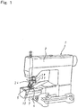
- Fig. 1 is an entire appearance perspective view showing an embodiment of the high frequency sewing machine according to the present invention.
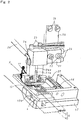
- Fig. 2 is an enlarged perspective view of important parts of the high frequency sewing machine.
- Fig. 3 is an enlarged longitudinal sectional view of the important parts of the high frequency sewing machine.
- reference numeral 1 denotes a sewing machine body.
- the sewing machine body 1 includes a sewing machine arm section 2 and a sewing machine bed section 3.
- the outer shell of the arm section 3 is formed in a substantially square tubular shape when viewed from a direction orthogonal to a processing advance direction X.
- a work material mounting plate (corresponding to a needle plate in a general sewing machine) 4 for slidably and movably mounting a work material H including a fiber cloth W, and a sliding plate 5 are attached to the upper wall of the substantially square tubular shaped bed section 3.
- the upper surfaces of the work material mounting plate 4 and the sliding plate 5 are substantially flush with the upper surface of the upper wall of the bed section 3.
- the work material mounting plate 4 is made of engineering plastic which is a material of construction such as polyamide, polyacetal, ABS, or polycarbonate and has wear resistance, corrosion resistance, electrical insulating properties and heat resistance.
- FIG. 2 and 6 four rows of slot-like elongated holes parallel to one another are penetratedly formed in the work material mounting plate 4.
- Two rows of slot-like elongated holes 6a of these four rows of slot-like elongated holes 6 which are located at the widthwise mid portions of the work material mounting plate 4 are divided at their respective longitudinal midpositions into two front and rear stages in the processing advance direction X with an installation hole 7 of a later-described lower planar plus electrode 16 interposed therebetween.
- Feed dogs 8 are disposed in these four rows of elongated holes 6. These feed dogs 8 intermittently transfer the work material H mounted on the work material mounting plate 4 along a horizontal plane in a specific direction, namely, the processing advance direction X by a combination of horizontal movement and vertical movement (synthetic circular movement).
- these feed dogs 8 include a front feed dog 8A including short feed dogs 8a moving within the front elongated hole portions of the slot-like elongated holes 6a divided into the two front and rear stages, and a rear feed dog 8B including short feed dogs 8b moving within the rear elongated portions of the slot-like elongated holes 6a.
- These front feed dog 8A and the rear feed dog 8B are made of engineering plastic which is a material of construction such as polyamide, polyacetal, ABS, or polycarbonate and has wear resistance, corrosion resistance, electrical insulating properties and heat resistance.
- These front feed dog 8A and the rear feed dog 8B are respectively fixed through set screws 10A and 10B to a front feed dog mounting base 9A and a rear feed dog mounting base 9B disposed within the bed section 3 below the work material mounting plate 4.
- the front feed mounting base 9A and the rear fed dog mounting base 9B are interlockingly connected to a drive mechanism assembled in the bed section 3 so that the front feed dog 8A and the rear feed dog 8B repeat the synthetic circular movement.
- the feed dog drive mechanism has the same construction as that employed in the general sewing machine, which is well known. Therefore, the detailed description thereof is omitted here.
- the feed dogs 8 (the front feed dog 8A and the rear feed dog 8B) and the feed dog drive mechanism constitute the intermittent transfer device alternately repeating the mode for transferring the work material H in the processing advance direction X, and the mode for stopping the transfer.
- the material of construction of the work material mounting plate 4 it is preferable to use super engineering plastic composed of polyetheretherketone resin. In this case, the heat resistance and wear resistance of the work material mounting plate 4 can be further improved.
- the material of construction of the front feed dog 8A and the rear feed dog 8B it is also preferable to use super engineering plastic composed of polyetheretherketone resin. In this case, the heat resistance and wear resistance of the front and rear feed dogs 8A and 8B can be further improved.
- a presser foot 12 is disposed at a location above the work material mounting plate 4 and opposed to the front feed dog 8A and the rear feed dog 8B of the feed dogs 8.
- the presser foot 12 cooperates with these feed dogs 8 (the front and rear feed dogs 8A and 8B) to transfer the work material H in the processing advance direction X, and also presses the work material H through the resilient force of a spring 11 toward the feed dogs 8 so that the work material H does not rise.
- the presser foot 12 is fixed through a fitting attachment 14 to the lower end of a pressure rod 13 supported at the distal end of arm section 2 so that it can reciprocatingly move up and down.
- the pressure rod 13 is movable up and down through the drive mechanism assembled in the arm section 2. That is, the pressure rod 13 moves up and releases the pressure against the work material H during the transfer operation by the feed dogs 8, and it moves down so that the presser food 12 resiliently presses the work material H during the transfer stopping time.
- the drive mechanism for moving up and down the pressure rod 13 is identical to that employed in the general sewing machine, which is well known. Therefore, the detailed description thereof is omitted here.
- a hold-down surface 12a of the presser foot 12 has at least a width not less than the transfer width of the feed dogs 8 and is formed long in the processing advance direction X.
- a minus electrode line 15 led out of a high frequency power source (not shown) comprised of a high frequency oscillator and a high frequency matching regulator is connected to the side surface of the presser foot 12.
- the presser foot 12 also serves as the upper planar minus electrode of the paired electrodes to which high frequency power is applied from the high frequency power source.
- An upwardly opening electrode mounting base 17 is secured in the bed section 3 below the work material mounting plate 4 as shown in Figs. 2 and 6 .
- a recessed groove 17a is formed in the upper surface of the electrode mounting base 17.
- a lower planar plus electrode 16 whose side surface is connected to a plus electrode line 19 led out of the high frequency electrode source (not shown) is fit into the recessed groove 17a, and also fixed to the electrode mounting base 17 through a set screw 18.
- an electrode surface 16a having a certain area faces the installation hole 7 formed in the work material mounting plate 4, and is secured to be flush with the upper surface of the work material mounting plate 4.
- an insulating block 21 made of engineering plastic is fixed through a set screw 22 to a mounting base 20 fixed to the arm section 2 through a set screw 29.
- a preheating cartridge heater 25 is insertedly retained in a cartridge heater retainer 24 fixed to the insulating block 22 through a set screw 23, and a ground wire 26 is connected to the preheating cartridge heater 24.
- a forked vertical sliding groove 24a is formed in the preheating cartridge heater retainer 24.
- a heat conductive member 27 having an an engaging piece 27a engageable into the vertical sliding groove 24a is fixed through a set screw 38 to the upper surface of the upper planar minus electrode 12 whose purpose is served by the presser foot.
- the preheating (heating) caloric value from the preheating cartridge heater 25 is transmitted all the time to the planar minus electrode 12 through the heat conductive member 27 so that the minus electrode 12 can be kept at high temperature.
- a preheating cartridge heater 28 is insertedly retained in a horizontal basal end 16b of the lower planar plus electrode 16 fixed to the electrode mounting base 17.
- the preheating (heating) caloric value from the preheating cartridge heater 28 is transmitted all the time to the planar plus electrode 16 so that the plus electrode 16 can be kept at high temperature.
- heat (temperature) sensors 30 and 31 are attached to the side surface of the preheating cartridge heater retainer 24 and the side surface of the lower planar plus electrode 16, respectively.
- the work material H in which the end of the fiber cloth W is turned back and stacked one upon another, and a hot melt (for example, the trade name "DAN-FUSE" manufactured by NITTO BOSEKI CO., LTD.) T that is a thermoplastic resin tape whose both the top and bottom surfaces are bonding surfaces is held between the overlapped end portions thereof, is previously placed at a location on the nearside on the work material mounting plate 4.
- a hot melt for example, the trade name "DAN-FUSE" manufactured by NITTO BOSEKI CO., LTD.
- the work material H thus prepared is mount (set) on the upper surface of the work material mounting plate 4, and the sewing machine is then started.
- the work material H is intermittently transferred along the horizontal surface in the predetermined processing advance direction X.
- the thermoplastic resin tape T held between the overlapped end portions of the fiber cloth W is melt for each certain area, and the overlapped end portions of the fiber cloth W are sequentially bonded together, and the same portions are repeatedly bonded together.
- the overlapped end portions of the fiber cloth W are bonded together through the thermoplastic resin tape T melt in the situation where it makes surface contact for each certain area.
- the heat obtained from the enhanced high frequency power can be dispersed into the surface contact portions between the paired electrodes 12 and 16 without being concentrated at linear or point contact portions. This prevents the occurrence of defective products having burn and burn holes due to heat concentration at the minute area. Consequently, owing to the absence of the defected portions due to the heat concentration and the achievement of assured uniform bonding strength, if the work material H is the fiber cloth W that is weak against heat, satisfactorily finished products can be surely and stably manufactured and processed.
- the transfer means of the work material H is one which is achieved by the cooperation between the feed dogs 8 which intermittently transfer it along the horizontal surface of the upper surface of the work material mounting plate 4 in the processing advance direction X by the combination of the horizontal movement and the vertical movement, and the presser foot 12 which presses the work material H including the fiber cloth W toward the work material mounting plate 4 so as not to rise during the transfer by the feed dogs 8. It is therefore easy to perform any optional curvilinear transfer besides linear transfer. Even when using the stretchable fiber cloth W, the fiber cloth W can be transferred as it is without exerting excess clamping force. Accordingly, the apparel products having many curvilinear portions and frequently using the stretchable fiber cloth can also be sufficiently handled, thereby surely and stably performing the predetermined bonding process.
- the presser foot 12 also serves as the upper planar electrode, thereby eliminating the need to dispose the upper electrode separately from the presser foot 12. This decreases the number of components and also eliminates the need to dispose and fix the upper electrode at the location of the presser foot 12, and the need to carry out special structural devices for electrical insulating properties of the presser foot. This further simplifies the entire structure and facilitates cost reduction.
- the work material mounting plate 4 and the feed dogs 8 are composed of the material having excellent wear resistance, electrical insulating properties and heat resistance, such as engineering plastic or super engineering plastic, it is capable of sufficiently ensuring the structural strength of the work material mounting plate 4 and the feed dogs 8, and also highly maintaining the durability of the work material mounting plate 4 and the feed dogs 8 which have excellent wear resistance, corrosion resistance, electrical insulating properties and heat resistance and are used under conditions where high frequency power is applied.
- the preheating cartridge heaters 25 and 28 are annexed to the pair of planar electrodes 12 and 16, respectively, owing to the preheating, the upper and lower electrodes 12 and 16 can be kept at high temperature even during the transfer operation by the feed dogs 8. Therefore, the predetermined bonding strength can be stably obtained by surely melting the resin tape T all the time, while more surely preventing the occurrence of burn or the like due to excessive heating by minimizing the high frequency power applied to these electrode 12 and 16 during the transfer stopping time.
- the presser foot 12 also serves as the upper planar electrode
- the cartridge heater retainer 29 retaining the preheating cartridge heater 25 which preheats the presser foot 12 and is secured in the arm section 2
- the heat conductive member 27 is interposed for connecting the presser foot 12 and the cartridge heater retainer 29 so that both can relatively slide up and down. Consequently, the increase in the weight of the presser foot (upper electrode) 12 is minimized to achieve smooth transfer of the workmaterial H including the fiber cloth W, and facilitate the operation for the curvilinear transfer carried out against the weight of the presser foot 12.
- the heat of the preheating cartridge heater 25 can be efficiently transmitted to the presser foot 12 through the heat conductive member 27, and the occurrence of burn or the like can be prevented and the stable bonding strength can be ensured owing to the effect of preheating of the electrode 12.
- the foregoing embodiment showed one in which the presser foot 12 also serves as the upper planar electrode.
- the upper planar electrode may be disposed separately from the presser foot 12.
- the presser foot 12 be made of a material of construction such as engineering plastic or super engineering plastic which has excellent wear resistance, electrical insulating properties and heat resistance.
- a mechanism for moving up and down the upper planar electrode in synchronism with the moving up and down of the presser foot 12 becomes necessary.
- it may be one in which the mode for transferring the work material H in the processing advance direction X, and the mode for stopping the transfer are alternately switchable by driving all the time a belt conveyor with a plurality of rows of projections arranged in parallel, and by causing the belt conveyor with the projections to move up and down through an elongated hole formed in the fiber cloth mounting plate 4.
- the bed section 3 includes the tubular bed whose shell is formed in the substantially square tubular shape when viewed from the direction orthogonal to the processing advance direction X.
- a predetermined bonding operation can be carried out by inserting from the front these tubular portions into the tubular bed section 3, and by subjecting these tubular portions to intermittent transfer so that they are rotated around the bed section 3. This is extremely convenient for handling the work material including the fiber cloth.
- the present invention is not limited to the application to the tubular sewing machine described in the foregoing embodiment.
- the present invention is applicable to a so-called flatbed sewing machines in which the whole of a bed surface 3A of the bed section 3 is shaped as a substantially rectangular flat surface, as shown in Fig. 7 .
- a predetermined bonding can be surely easily carried out with the entire work material stably supported on the large flat bed surface 3A.
Landscapes
- Engineering & Computer Science (AREA)
- Mechanical Engineering (AREA)
- Physics & Mathematics (AREA)
- Thermal Sciences (AREA)
- Textile Engineering (AREA)
- Sewing Machines And Sewing (AREA)
- Lining Or Joining Of Plastics Or The Like (AREA)
- Treatment Of Fiber Materials (AREA)
Description
- The present invention relates to a high frequency sewing machine used for manufacturing and processing apparel products (textile products) such as women's clothing, children's clothing and men's clothing in which clothes of natural fibers represented by cotton, wool, silk, or the like, or synthetic fibers represented by polyester, nylon, acryl, or the like (hereinafter referred to as "fiber clothes" in the present invention) are used as object materials, and overlapped portions such as the overlapped ends of these fiber clothes are bonded (welded) together through a thermoplastic resin tape melt under high frequency dielectric heating.
- As this type of high frequency sewing machine, a large number of ones have been developed and have come in practice in which a work material itself is for example a thermoplastic synthetic resin sheet such as of vinyl chloride resin or a synthetic resin film, and the overlapped portions of the work material are welded. These high frequency sewing machines are required to include only a transfer means for transferring the resin sheet or the resin film as a work material along the longitudinal direction of the overlapped portions; and a pair of electrodes for applying high frequency power to the overlapped portions of the resin sheet or the resin film transferred by the transfer means. Compared to general sewing machines which sew together the fiber clothes by forming seams by lacing or looping sewing threads such as a needle thread (upper thread), a looper thread, a lower thread, it is possible to omit the use of a plurality of complicated mechanisms and parts for constituting the sewing construction, for example, the constructions required in these sewing machines, such as feed dogs for transferring a fiber cloth in the sewing advance direction, a needle and a needle vertical reciprocating movement mechanism for causing the thread to pass through the fiber cloth, a rotary hook for supplying the lower thread and a hook operating mechanism for lacing and looping, or a looper and a looper operating mechanism for supplying the looper thread. That is, the whole structure of the sewing machine can be simplified.
- In the existing high frequency sewing machines having a simpler construction than the general sewing machines, a means for bonding the overlapped portions of a work material (a thermoplastic resin sheet or a resin film) in which the work material itself is melt under high frequency dielectric heating by applying high frequency power between a pair of upper and lower electrode rollers while continuously transferring the work material held between the pair of electrode rollers in a certain direction has heretofore been employed as disclosed in Japanese Unexamined Patent Application Publications Nos.
6-218819 6-155576 - As disclosed in Japanese Patent No.
4022539 - In each of these conventional high frequency sewing machines disclosed in the publications Nos.
6-218819 6-155576 4022539 - In the means for enhancing the value of high frequency power, the heat of the enhanced high frequency power is concentratedly exerted on the line or point contact portions, so that the work material is susceptible to insulation breakdown, causing defective portions such as burn and burn holes (scorches). Particularly, when the work material is a thin fiber cloth that is the object material of the present invention, there is the problem that the burn range is likely to momentarily expand and hence a large number of defective products are manufactured. In the case of employing the means for decreasing the transfer rate of the paired electrode rollers by setting a low value of high frequency power, there is the problem that processing efficiency is extremely deteriorated. As disclosed in the patent No.
4022539 - In manufacturing and processing apparel products using the fiber clothes as the object material, in many cases, it is required to bond curvilinear portions as in women's underwear or the like. There are also many cases of using stretchable fiber clothes. Sewing machines used for manufacturing and processing the apparel products should be able to handle the bonding of the curvilinear portions and the bonding of the stretchable fiber clothes. However, the conventional high frequency sewing machines adapted to linearly transfer a workmaterial in a certain direction with the work material held between the paired electrode rollers cannot sufficiently handle the bonding of the curvilinear portions and the bonding of the stretchable fiber clothes. That is, the conventional high frequency sewing machines using the paired electrode rollers are suitable for the bonding process of the overlapped portions while linearly transferring unstretchable work material such as resin sheets, but unsuitable for manufacturing and processing the apparel products in which the fiber clothes are used as the object materials, and the bonding of curvilinear portions is frequently performed, and the stretchable materials are frequently used. Hence, it can be said to be substantially impossible that the conventional high frequency sewing machines are directly applied to the bonding of the fiber clothes.
-
US-A-2666472 discloses a high frequency sewing machine comprising a work material mounting plate, an intermittent transfer device, presser foot, and a pair of upper and lower electrode. In a state where the work material is held between the pair of upper and lower electrodes by moving down the upper electrode during time when a transfer by the intermittent transfer device is stopped, the overlapped portions of a fiber cloth are continuously bonded together by allowing a thermoplastic resin tape to melt under high frequency dielectric heating. - In view of the foregoing circumstances, the present invention has for its object to provide a high frequency sewing machine which is capable of obtaining the assured uniform bonding strength by using high frequency power, and preventing the manufacturing and processing of defective products having burn, burn holes or the like, and also satisfactorily handling the bonding of curvilinear portions or stretchable fiber clothes.
- The high frequency sewing machine according to the present invention is the high frequency sewing machine according to
claim 1, in particular including a work material mounting plate which is attached to an upper wall of a sewing machine bed section and slidingly movably mounts a work material with a thermoplastic resin tape interposed between overlapped portions of a fiber cloth; an intermittent transfer device which is disposed in the bed section below the work material mounting plate and alternately repeats a mode for abutting against the lower surface of the work material mounted on the work material mounting plate and transferring the work material along a horizontal surface in a specific processing advance direction, and a mode for separating from the lower surface of the work material and stopping the transfer of the work material; a presser foot which cooperates with the intermittent transfer device to transfer the work material in the processing advance direction and reciprocatingly move up and down to resiliently press the work material during the transfer stopping time; and an upper planar electrode which is disposed above the work material mounting plate and reciprocatingly moves up and down, and a lower planar electrode which is disposed and secured in the bed section below the work material mounting plate and has an electrode surface flush with the upper surface of the work material mounting plate. In a state where the work material is held between the upper planar electrode and the lower planar electrode by moving down the upper planar electrode during the time when the transfer by the intermittent transfer device is stopped, the overlapped portions of the fiber cloth are continuously bonded together by allowing the thermoplastic resin tape to melt under high frequency dielectric heating by applying high frequency power between the paired upper and lower planar electrodes. - According to the high frequency sewing machine thus constructed, while intermittently transferring the work material including the fiber cloth along the horizontal surface by the cooperation between the intermittent transfer device and the presser foot, the heat obtained from the high frequency output applied between the paired upper and lower planar electrodes during the transfer stopping time is transmitted to the thermoplastic resin tape held between the overlapped portions of the fiber cloth. Thereby, the overlapped portions of the fiber cloth can be sequentially bonded by allowing the resin tape to melt planarly, namely, for each certain area. It is also capable of repetitively bond the same portion. Assured uniform bonding strength is achieved by repetitive bonding under application of low high-frequency power, and the heat obtained from the high frequency power can be distributed into the surface contact portions of the paired electrodes without being concentrated in linear or point contact portions. It is therefore capable of avoiding the occurrence of defective portions such as burn or burn holes (scorches) of the fiber cloth due to concentration of the heat obtained from the high frequency power into a minute area. Along with the assured uniform bonding strength as described above, satisfactorily finished apparel products can be surely manufactured and processed if the object material is a fiber cloth that is weak against heat.
- Additionally, the transfer means of the work material is one which is achieved by the cooperation between the intermittent transfer device alternately repeating the mode for abutting against the lower surface of the work material mounted on the work material mounting plate and transferring the work material along the horizontal surface in the specific processing advance direction, and the mode for separating from the lower surface of the work material and stopping the transfer of the work material; and the presser foot which presses the work material toward the work material mounting plate so as not to rise during the transfer by the intermittent transfer device. It is therefore capable of optionally change the direction of the work material against the pressing force of the presser foot during the transfer stopping time. It is also easy to perform any optional curvilinear transfer besides linear transfer. Even when handling the stretchable fiber cloth, the fiber cloth can be transferred as it is without exerting excess clamping force. That is, the bonding of curvilinear portions and the bonding of stretchable fiber clothes can be sufficiently handled. This produces the effect of provision of the high frequency sewing machine extremely suitable and practical for manufacturing and processing the apparel products having many curvilinear portions and frequently using the stretchable fiber cloth.
- In the high frequency sewing machine according to the present invention, it is provided to use as the intermittent transfer device an intermittent transfer device comprised of feed dogs disposed in slot-like elongated holes formed in the work material mounting plate, and a feed dog drive mechanism for subjecting the feed dogs to synthetic circular movement in vertical and horizontal directions within the slot-like elongated holes.
- In this case, it is possible to directly and effectively utilize the manufacturing technique and assembly technique already established for well-known intermittent transfer devices comprised of feed dogs and a feed dog drive mechanism, which are included in a conventionally known general sewing machine. This minimizes burdens on design and production, for example, the development and manufacturing of a special intermittent transfer device intended for the high frequency sewing machine, and considerable changes of the sewing machine bed section in the general sewing machine in order to assemble the special intermittent transfer device. This improves the productivity of the high frequency sewing machine as a whole and reduces the manufacturing costs thereof, thus achieving the high frequency sewing machine having high performance and high quality.
- In the high frequency sewing machine according to the present invention, it is preferable that the presser foot also serve as the upper planar electrode of the paired upper and lower planar electrodes.
- In this case, the presser foot performing the intermittent transfer of the work material in cooperation with the intermittent transfer device can also serve as the upper planar electrode, thereby eliminating the need to dispose the upper electrode separately from the presser foot. This reduces the number of components, and requires no special devices for separately arranging and fixing the upper electrode at the location of the presser foot and for insulating the presser foot, thereby achieving a further simplified entire structure and further cost reduction.
- In the high frequency sewing machine according to the present invention, the work material mounting plate, and a part of the intermittent transfer means which abuts against the lower surface of the work material, or the feed dogs are made of a material having electrical insulating properties and heat resistance, such as engineering plastic.
- This ensures sufficient structural strength of the work material mounting plate and the part of the intermittent transmit means which abuts against the lower surface of the work material, or the feed dogs. This also imparts excellent wear resistance, corrosion resistance, electrical insulating properties and heat resistance, thereby improving the durability of the individual components used under circumstances where the high frequency power is applied.
- In the high frequency sewing machine according to the present invention, preheating heaters are preferably annexed to the paired upper and lower planar electrodes, respectively.
- In this case, the upper and lower electrodes can be retained at a predetermined temperature by preheating them during the time when the transfer by the intermittent transfer device is stopped. Therefore, the resin tape can be surely melted and the predetermined bonding strength can be obtained stably while more surely preventing the occurrence of spark by minimizing high frequency power applied to these electrodes.
- In the high frequency sewing machine according to the present invention in which the presser foot also serves as the upper planar electrode, it is preferable that between the presser foot also serving as the upper planar electrode, and a heater retainer which retains the preheating heater for preheating the presser foot and is fixedly attached to a sewing machine body, a heat conductive member be interposed for connecting the presser foot and the heat retainer so that both can relatively slide up and down.
- In this case, the increase in the weight of the presser foot (the upper electrode) is minimized to achieve a smooth transfer of the work material and facilitate the operation for curvilinear transfer. Additionally, the heat of the preheating heaters can be efficiently transmitted to the presser foot through the heat conductive member. Owing to the effect of preheating these electrodes, it is capable of preventing the occurrence of spark and ensuring stable bonding strength.
- In the high frequency sewing machine according to the present invention, the outer shell of the sewing machine bed section may be formed in a substantially tubular shape when viewed from a direction orthogonal to the processing advance direction. Alternatively, the whole of the bed surface including the work material mounting plate may be shaped as a substantially rectangular flat surface.
- In the application to a sewing machine having a so-called tubular bed whose outer shell is formed in the substantially tubular shape as in the former case, it is extremely convenient for handling the work material when bonding relatively small tubular portions such as cuffs and necks. In the application to a so-called flatbed sewing machine whose entire bed surface is shaped as the substantially rectangular flat surface as in the latter case, when bonding a large work material that is difficult to handle, a predetermined bonding can be surely carried out with the work material stably supported on the large flat bed surface.
- These and other characteristic features of the present invention and the effects thereof will become apparent from the following description of embodiments.
-
-
Fig. 1 is an entire appearance perspective view showing an embodiment of a high frequency sewing machine according to the present invention; -
Fig. 2 is an enlarged perspective view of important parts of the high frequency sewing machine; -
Fig. 3 is an enlarged longitudinal sectional view of the important parts of the high frequency sewing machine; -
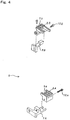
Fig. 4 is an exploded perspective view showing the feed dog construction in the high frequency sewing machine; -
Fig. 5 is an exploded perspective view for explaining the attached state of an upper planar electrode in the high frequency sewing machine; -
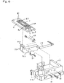
Fig. 6 is an exploded perspective view for explaining the attached state of a lower planar electrode in the high frequency sewing machine; and -
Fig. 7 is an entire appearance perspective view showing another embodiment of the high frequency sewing machine according to the present invention. - Embodiments of the present invention are described below with reference to the accompanying drawings.
-
Fig. 1 is an entire appearance perspective view showing an embodiment of the high frequency sewing machine according to the present invention.Fig. 2 is an enlarged perspective view of important parts of the high frequency sewing machine.Fig. 3 is an enlarged longitudinal sectional view of the important parts of the high frequency sewing machine. In theseFigs. 1 to 3 ,reference numeral 1 denotes a sewing machine body. Thesewing machine body 1 includes a sewingmachine arm section 2 and a sewingmachine bed section 3. - The outer shell of the
arm section 3 is formed in a substantially square tubular shape when viewed from a direction orthogonal to a processing advance direction X. A work material mounting plate (corresponding to a needle plate in a general sewing machine) 4 for slidably and movably mounting a work material H including a fiber cloth W, and a slidingplate 5 are attached to the upper wall of the substantially square tubular shapedbed section 3. The upper surfaces of the workmaterial mounting plate 4 and the slidingplate 5 are substantially flush with the upper surface of the upper wall of thebed section 3. The workmaterial mounting plate 4 is made of engineering plastic which is a material of construction such as polyamide, polyacetal, ABS, or polycarbonate and has wear resistance, corrosion resistance, electrical insulating properties and heat resistance. - As shown in
Figs. 2 and6 , four rows of slot-like elongated holes parallel to one another are penetratedly formed in the workmaterial mounting plate 4. Two rows of slot-like elongated holes 6a of these four rows of slot-like elongated holes 6 which are located at the widthwise mid portions of the workmaterial mounting plate 4 are divided at their respective longitudinal midpositions into two front and rear stages in the processing advance direction X with aninstallation hole 7 of a later-described lowerplanar plus electrode 16 interposed therebetween.Feed dogs 8 are disposed in these four rows of elongated holes 6. Thesefeed dogs 8 intermittently transfer the work material H mounted on the workmaterial mounting plate 4 along a horizontal plane in a specific direction, namely, the processing advance direction X by a combination of horizontal movement and vertical movement (synthetic circular movement). - As shown in
Fig. 4 , thesefeed dogs 8 include a front feed dog 8A includingshort feed dogs 8a moving within the front elongated hole portions of the slot-like elongated holes 6a divided into the two front and rear stages, and arear feed dog 8B including short feed dogs 8b moving within the rear elongated portions of the slot-like elongated holes 6a. These front feed dog 8A and therear feed dog 8B are made of engineering plastic which is a material of construction such as polyamide, polyacetal, ABS, or polycarbonate and has wear resistance, corrosion resistance, electrical insulating properties and heat resistance. These front feed dog 8A and therear feed dog 8B are respectively fixed throughset screws 10A and 10B to a front feed dog mounting base 9A and a rear feed dog mounting base 9B disposed within thebed section 3 below the workmaterial mounting plate 4. - The front feed mounting base 9A and the rear fed dog mounting base 9B are interlockingly connected to a drive mechanism assembled in the
bed section 3 so that the front feed dog 8A and therear feed dog 8B repeat the synthetic circular movement. The feed dog drive mechanism has the same construction as that employed in the general sewing machine, which is well known. Therefore, the detailed description thereof is omitted here. - The feed dogs 8 (the front feed dog 8A and the
rear feed dog 8B) and the feed dog drive mechanism constitute the intermittent transfer device alternately repeating the mode for transferring the work material H in the processing advance direction X, and the mode for stopping the transfer. - As the material of construction of the work
material mounting plate 4, it is preferable to use super engineering plastic composed of polyetheretherketone resin. In this case, the heat resistance and wear resistance of the workmaterial mounting plate 4 can be further improved. - As the material of construction of the front feed dog 8A and the
rear feed dog 8B, it is also preferable to use super engineering plastic composed of polyetheretherketone resin. In this case, the heat resistance and wear resistance of the front andrear feed dogs 8A and 8B can be further improved. - A
presser foot 12 is disposed at a location above the workmaterial mounting plate 4 and opposed to the front feed dog 8A and therear feed dog 8B of thefeed dogs 8. Thepresser foot 12 cooperates with these feed dogs 8 (the front andrear feed dogs 8A and 8B) to transfer the work material H in the processing advance direction X, and also presses the work material H through the resilient force of aspring 11 toward thefeed dogs 8 so that the work material H does not rise. Thepresser foot 12 is fixed through afitting attachment 14 to the lower end of apressure rod 13 supported at the distal end ofarm section 2 so that it can reciprocatingly move up and down. Thepressure rod 13 is movable up and down through the drive mechanism assembled in thearm section 2. That is, thepressure rod 13 moves up and releases the pressure against the work material H during the transfer operation by thefeed dogs 8, and it moves down so that thepresser food 12 resiliently presses the work material H during the transfer stopping time. - The drive mechanism for moving up and down the
pressure rod 13 is identical to that employed in the general sewing machine, which is well known. Therefore, the detailed description thereof is omitted here. - A hold-
down surface 12a of thepresser foot 12 has at least a width not less than the transfer width of thefeed dogs 8 and is formed long in the processing advance direction X. As shown inFig. 5 , aminus electrode line 15 led out of a high frequency power source (not shown) comprised of a high frequency oscillator and a high frequency matching regulator is connected to the side surface of thepresser foot 12. Thus, thepresser foot 12 also serves as the upper planar minus electrode of the paired electrodes to which high frequency power is applied from the high frequency power source. - An upwardly opening
electrode mounting base 17 is secured in thebed section 3 below the workmaterial mounting plate 4 as shown inFigs. 2 and6 . A recessedgroove 17a is formed in the upper surface of theelectrode mounting base 17. A lower planar pluselectrode 16 whose side surface is connected to aplus electrode line 19 led out of the high frequency electrode source (not shown) is fit into the recessedgroove 17a, and also fixed to theelectrode mounting base 17 through aset screw 18. - In the lower
planar plus electrode 16, anelectrode surface 16a having a certain area faces theinstallation hole 7 formed in the workmaterial mounting plate 4, and is secured to be flush with the upper surface of the workmaterial mounting plate 4. - As shown
Figs. 2 and5 , an insulatingblock 21 made of engineering plastic is fixed through aset screw 22 to a mountingbase 20 fixed to thearm section 2 through aset screw 29. A preheatingcartridge heater 25 is insertedly retained in acartridge heater retainer 24 fixed to the insulatingblock 22 through aset screw 23, and aground wire 26 is connected to the preheatingcartridge heater 24. A forked vertical sliding groove 24a is formed in the preheatingcartridge heater retainer 24. On the other hand, a heatconductive member 27 having an anengaging piece 27a engageable into the vertical sliding groove 24a is fixed through aset screw 38 to the upper surface of the upper planarminus electrode 12 whose purpose is served by the presser foot. By engaging theengaging piece 27a of the heatconductive member 27 into the vertical sliding groove 24a of the preheatingcartridge heater retainer 24 so as to be relatively slidable up and down, the preheating (heating) caloric value from the preheatingcartridge heater 25 is transmitted all the time to theplanar minus electrode 12 through the heatconductive member 27 so that theminus electrode 12 can be kept at high temperature. - Additionally, as shown in
Fig. 6 , a preheatingcartridge heater 28 is insertedly retained in a horizontal basal end 16b of the lowerplanar plus electrode 16 fixed to theelectrode mounting base 17. Thus, the preheating (heating) caloric value from the preheatingcartridge heater 28 is transmitted all the time to theplanar plus electrode 16 so that theplus electrode 16 can be kept at high temperature. - To perform feedback control of the preheating temperatures of the upper planar
minus electrode 12 and the lowerplanar plus electrode 16 in order to keep them at a constant temperature, heat (temperature)sensors 30 and 31 are attached to the side surface of the preheatingcartridge heater retainer 24 and the side surface of the lowerplanar plus electrode 16, respectively. - In the high frequency sewing machine thus constructed, as shown in
Figs. 2 and3 , the work material H, in which the end of the fiber cloth W is turned back and stacked one upon another, and a hot melt (for example, the trade name "DAN-FUSE" manufactured by NITTO BOSEKI CO., LTD.) T that is a thermoplastic resin tape whose both the top and bottom surfaces are bonding surfaces is held between the overlapped end portions thereof, is previously placed at a location on the nearside on the workmaterial mounting plate 4. - The work material H thus prepared is mount (set) on the upper surface of the work
material mounting plate 4, and the sewing machine is then started. By the cooperation between the synthetic movement of the feed dogs 8 (the front andrear feed dogs 8A and 8B of the feed dogs 8) and the vertical reciprocating movement of thepresser foot 12, the work material H is intermittently transferred along the horizontal surface in the predetermined processing advance direction X. By heating the paired upper and lowerplanar electrodes electrodes
Thus, the overlapped end portions of the fiber cloth W are bonded together through the thermoplastic resin tape T melt in the situation where it makes surface contact for each certain area. Hence, if relatively enhanced high frequency power is applied to the pairedelectrodes electrodes - Additionally, the transfer means of the work material H is one which is achieved by the cooperation between the
feed dogs 8 which intermittently transfer it along the horizontal surface of the upper surface of the workmaterial mounting plate 4 in the processing advance direction X by the combination of the horizontal movement and the vertical movement, and thepresser foot 12 which presses the work material H including the fiber cloth W toward the workmaterial mounting plate 4 so as not to rise during the transfer by thefeed dogs 8. It is therefore easy to perform any optional curvilinear transfer besides linear transfer. Even when using the stretchable fiber cloth W, the fiber cloth W can be transferred as it is without exerting excess clamping force. Accordingly, the apparel products having many curvilinear portions and frequently using the stretchable fiber cloth can also be sufficiently handled, thereby surely and stably performing the predetermined bonding process. - As described in the foregoing embodiment, the
presser foot 12 also serves as the upper planar electrode, thereby eliminating the need to dispose the upper electrode separately from thepresser foot 12. This decreases the number of components and also eliminates the need to dispose and fix the upper electrode at the location of thepresser foot 12, and the need to carry out special structural devices for electrical insulating properties of the presser foot. This further simplifies the entire structure and facilitates cost reduction. - Particularly, as described in the foregoing embodiment, when the work
material mounting plate 4 and thefeed dogs 8 are composed of the material having excellent wear resistance, electrical insulating properties and heat resistance, such as engineering plastic or super engineering plastic, it is capable of sufficiently ensuring the structural strength of the workmaterial mounting plate 4 and thefeed dogs 8, and also highly maintaining the durability of the workmaterial mounting plate 4 and thefeed dogs 8 which have excellent wear resistance, corrosion resistance, electrical insulating properties and heat resistance and are used under conditions where high frequency power is applied. - As described in the foregoing embodiment, when the preheating
cartridge heaters planar electrodes lower electrodes feed dogs 8. Therefore, the predetermined bonding strength can be stably obtained by surely melting the resin tape T all the time, while more surely preventing the occurrence of burn or the like due to excessive heating by minimizing the high frequency power applied to theseelectrode - Further, in the case where the
presser foot 12 also serves as the upper planar electrode, between thepresser foot 12 serving as the upper planar electrode, and thecartridge heater retainer 29 retaining the preheatingcartridge heater 25 which preheats thepresser foot 12 and is secured in thearm section 2, the heatconductive member 27 is interposed for connecting thepresser foot 12 and thecartridge heater retainer 29 so that both can relatively slide up and down. Consequently, the increase in the weight of the presser foot (upper electrode) 12 is minimized to achieve smooth transfer of the workmaterial H including the fiber cloth W, and facilitate the operation for the curvilinear transfer carried out against the weight of thepresser foot 12. Furthermore, the heat of the preheatingcartridge heater 25 can be efficiently transmitted to thepresser foot 12 through the heatconductive member 27, and the occurrence of burn or the like can be prevented and the stable bonding strength can be ensured owing to the effect of preheating of theelectrode 12.
The foregoing embodiment showed one in which thepresser foot 12 also serves as the upper planar electrode. Alternatively, the upper planar electrode may be disposed separately from thepresser foot 12. In this case, it is required that thepresser foot 12 be made of a material of construction such as engineering plastic or super engineering plastic which has excellent wear resistance, electrical insulating properties and heat resistance. In addition, a mechanism for moving up and down the upper planar electrode in synchronism with the moving up and down of thepresser foot 12 becomes necessary.
The foregoing embodiment described as the intermittent transfer device one which uses thefeed dogs 8 performing the synthetic circular movement by combining the horizontal movement and the vertical movement. Alternatively, it may be one in which the mode for transferring the work material H in the processing advance direction X, and the mode for stopping the transfer are alternately switchable by driving all the time a belt conveyor with a plurality of rows of projections arranged in parallel, and by causing the belt conveyor with the projections to move up and down through an elongated hole formed in the fibercloth mounting plate 4. - Although the foregoing embodiment employed the cartridge type ones as the upper and lower preheating heaters, without being limited thereto, an electric heater or the like may be fixedly assembled.
- The foregoing embodiment described the application to the so-called tubular sewing machine in which the
bed section 3 includes the tubular bed whose shell is formed in the substantially square tubular shape when viewed from the direction orthogonal to the processing advance direction X. In this case, when bonding relatively small tubular portions such as cuffs and necks of various types of apparels, a predetermined bonding operation can be carried out by inserting from the front these tubular portions into thetubular bed section 3, and by subjecting these tubular portions to intermittent transfer so that they are rotated around thebed section 3. This is extremely convenient for handling the work material including the fiber cloth. - The present invention is not limited to the application to the tubular sewing machine described in the foregoing embodiment. For example, the present invention is applicable to a so-called flatbed sewing machines in which the whole of a
bed surface 3A of thebed section 3 is shaped as a substantially rectangular flat surface, as shown inFig. 7 . In this case, when bonding, for example, a long portion of a large fiber cloth that is difficult to handle, a predetermined bonding can be surely easily carried out with the entire work material stably supported on the largeflat bed surface 3A.
Claims (6)
- A high frequency sewing machine comprising:a work material mounting plate (4) which is attached to an upper wall of a sewing machine bed section (3) and slidingly movably mounts a work material (H) with a thermoplastic resin tape (T) interposed between overlapped portions of a fiber cloth (W);an intermittent transfer device which is disposed in the bed section (3) below the work material mounting plate (3) and alternately repeats a mode for abutting against a lower surface of the work material (H) mounted on the work material mounting plate (4) and transferring the work material (H) along a horizontal surface in a specific processing advance direction (X), and a mode for separating from the lower surface of the work material (H) and stopping the transfer of the work material;a presser foot (12) which is disposed above the work material mounting plate (4) cooperates with the intermittent transfer device to transfer the work material (H) in the processing advance direction (X), and is reciprocatingly movable up and down to resiliently press the work material (H) during time when a transfer is stopped; and characterized in that it comprises an upper planar electrode (12) which is disposed above the work material mounting plate (4) so as to be reciprocatingly movable up and down and has an electrode surface (12a) with a width not less than a transfer width of feed dogs of the intermittent transfer device in the processing advance direction (X), anda lower planar electrode (16) which is disposed and secured in the bed section (3) below the work material mounting plate (4) and has an electrode surface (16a) flush with an upper surface of the work material mounting plate (4) and is opposed to the electrode surface (12a) of the upper electrode (12), whereinin a state where the work material (H) is held between the electrode surface (12a) of the upper planar electrode (12) and the electrode surface (16a) of the lower planar electrode (16) by moving down the upper planar electrode (12) during the time when the transfer by the intermittent transfer device is stopped, the overlapped portions of the fiber cloth (W) are continuously bonded together by allowing the thermoplastic resin tape (T) to melt under high frequency dielectric heating by applying high frequency power between a pair of the upper (12) and lower (16) planar electrodes,wherein the intermittent transfer device comprises the feed dogs (8) disposed in slot-like elongated holes (6) formed in the work material mounting plate (4), and a feed dogs drive mechanism which causes synthetic circular movement of the feed dogs (8) in vertical and horizontal directions in the slot-like elongated holes (6),wherein the presser foot (12) serves as the upper planar electrode (12).
- The high frequency sewing machine according to claim 1, wherein the work material mounting plate (4) and the feed dogs (8) of the intermittent transfer device which abuts against the lower surface of the work material (H) are made of a material having electrical insulating properties and heat resistance, such as engineering plastic.
- The high frequency sewing machine according to any of the preceding claims, wherein preheating heaters (25, 28) are annexed to the pair of upper (12) and lower (16) planar electrodes, respectively.
- The high frequency sewing machine according to any of the preceding claims, wherein an outer shell of the bed section (3) is formed in a substantially tubular shape when viewed from a direction orthogonal to a processing advance direction.
- The high frequency sewing machine according to any of the preceding claims, wherein the entirety of a bed surface in the bed section (3) including the work material mounting plate (4) is formed in a shape having a substantially rectangular flat surface.
- The high frequency sewing machine according to claim 1, wherein, between the presser foot also serving as the upper planar electrode (12), and a heater retainer (24) which retains a preheating heater (25) for preheating the presser foot and is fixedly attached to a sewing machine body (1), a heat conductive member (27) is interposed for connecting the presser foot and the heat retainer (24) so that both can relatively slide up and down.
Applications Claiming Priority (2)
| Application Number | Priority Date | Filing Date | Title |
|---|---|---|---|
| JP2009192534 | 2009-07-31 | ||
| JP2010113646A JP5413848B2 (en) | 2009-07-31 | 2010-04-23 | High frequency sewing machine |
Publications (3)
| Publication Number | Publication Date |
|---|---|
| EP2281472A2 EP2281472A2 (en) | 2011-02-09 |
| EP2281472A3 EP2281472A3 (en) | 2015-05-27 |
| EP2281472B1 true EP2281472B1 (en) | 2017-12-20 |
Family
ID=43035501
Family Applications (1)
| Application Number | Title | Priority Date | Filing Date |
|---|---|---|---|
| EP10170754.5A Active EP2281472B1 (en) | 2009-07-31 | 2010-07-26 | High frequency sewing machine |
Country Status (6)
| Country | Link |
|---|---|
| US (1) | US8534337B2 (en) |
| EP (1) | EP2281472B1 (en) |
| JP (1) | JP5413848B2 (en) |
| KR (1) | KR101758143B1 (en) |
| CN (1) | CN101987508B (en) |
| TW (1) | TWI533999B (en) |
Families Citing this family (5)
| Publication number | Priority date | Publication date | Assignee | Title |
|---|---|---|---|---|
| JP5626719B2 (en) * | 2010-03-08 | 2014-11-19 | ヤマトミシン製造株式会社 | High frequency sewing machine |
| JP6155096B2 (en) * | 2013-05-28 | 2017-06-28 | グンゼ株式会社 | Bonding device |
| JP6164525B2 (en) * | 2013-09-21 | 2017-07-19 | ヤマトミシン製造株式会社 | High frequency sewing machine |
| KR101537505B1 (en) * | 2014-10-01 | 2015-07-17 | 호전실업 주식회사 | Preparation of down products having bonding pattern lines formed by high-frequency bonding technique |
| CN115214152B (en) * | 2022-07-01 | 2025-05-02 | 厦门优力播休闲用品有限公司 | A bonding device and method of using the same |
Family Cites Families (18)
| Publication number | Priority date | Publication date | Assignee | Title |
|---|---|---|---|---|
| US2322298A (en) * | 1941-02-28 | 1943-06-22 | Mercantile Commerce Bank And T | Thermal attaching machine |
| US2681976A (en) * | 1946-07-16 | 1954-06-22 | United Shoe Machinery Corp | Arrangement for progressive treatment with pulsed electrical energy |
| US2666472A (en) * | 1946-12-07 | 1954-01-19 | Union Carbide & Carbon Corp | Apparatus for making heat sealed ruffled articles |
| US2446623A (en) * | 1947-01-31 | 1948-08-10 | United Shoe Machinery Corp | High-frequency progressive bonding apparatus for plastic materials |
| US2539646A (en) * | 1947-03-19 | 1951-01-30 | United Shoe Machinery Corp | High-frequency progressive bonding apparatus |
| JPS5637307A (en) * | 1979-08-30 | 1981-04-11 | Bikutorii Kk | Wet suit processing machine |
| JPS63242627A (en) * | 1987-03-31 | 1988-10-07 | Popii Sangyo Kk | High-frequency welder |
| SE458591B (en) * | 1987-09-17 | 1989-04-17 | Kurt Andersson | DEVICE FOR THE PREPARATION OF AN EXISTING LONG-EXISTING FIBER MATERIAL |
| CN2038110U (en) * | 1988-09-30 | 1989-05-24 | 姜若愚 | Multi-function special sewing machine used for synthetic fabrics |
| JPH06155576A (en) * | 1992-11-18 | 1994-06-03 | Achilles Corp | Overlap splicing processing of synthetic resin film |
| JPH06218819A (en) * | 1993-01-28 | 1994-08-09 | Chisso Corp | Breadth jointing processing of synthetic resin film |
| JPH1024491A (en) * | 1996-07-11 | 1998-01-27 | Seidensha Denshi Kogyo Kk | Ultrasonic machining apparatus |
| JP3909449B2 (en) * | 1998-06-30 | 2007-04-25 | ヤマトミシン製造株式会社 | Sewing failure detection device |
| JP4189521B2 (en) * | 1999-06-15 | 2008-12-03 | ヤマトミシン製造株式会社 | Flat sewing machine for hem sewing with anti-sewing device |
| WO2004002248A2 (en) * | 2002-07-01 | 2004-01-08 | Sara Lee Corporation | Methods of making cotton blend glue brassieres |
| JP2006051169A (en) * | 2004-08-11 | 2006-02-23 | Gunze Ltd | Material displacement preventive feeder for flat stitch sewing machine |
| JP4022539B2 (en) * | 2004-11-08 | 2007-12-19 | クインライト電子精工株式会社 | High frequency sewing machine |
| TWI367273B (en) * | 2006-09-28 | 2012-07-01 | Clover Group Internat Ltd | A fabric-processing device with a presser foot and a methed of fusing an article of clothing |
-
2010
- 2010-04-23 JP JP2010113646A patent/JP5413848B2/en active Active
- 2010-06-25 TW TW099120774A patent/TWI533999B/en not_active IP Right Cessation
- 2010-07-26 EP EP10170754.5A patent/EP2281472B1/en active Active
- 2010-07-30 CN CN201010247320.9A patent/CN101987508B/en not_active Expired - Fee Related
- 2010-07-30 KR KR1020100073783A patent/KR101758143B1/en not_active Expired - Fee Related
- 2010-08-02 US US12/804,929 patent/US8534337B2/en not_active Expired - Fee Related
Non-Patent Citations (1)
| Title |
|---|
| None * |
Also Published As
| Publication number | Publication date |
|---|---|
| TW201103737A (en) | 2011-02-01 |
| US20110048645A1 (en) | 2011-03-03 |
| JP2011047099A (en) | 2011-03-10 |
| EP2281472A2 (en) | 2011-02-09 |
| US8534337B2 (en) | 2013-09-17 |
| TWI533999B (en) | 2016-05-21 |
| KR20110013316A (en) | 2011-02-09 |
| CN101987508B (en) | 2014-10-22 |
| CN101987508A (en) | 2011-03-23 |
| JP5413848B2 (en) | 2014-02-12 |
| EP2281472A3 (en) | 2015-05-27 |
| KR101758143B1 (en) | 2017-07-14 |
Similar Documents
| Publication | Publication Date | Title |
|---|---|---|
| US8534337B2 (en) | High frequency sewing machine | |
| EP2364607B1 (en) | High frequency sewing machine | |
| US4665844A (en) | Curved cloth stretch frame construction for an embroidery sewing machine | |
| GB2520600A (en) | High frequency sewing machine | |
| TWI731055B (en) | High frequency sewing machine | |
| EP2458053B1 (en) | Feeding device of sewing machine | |
| US2472820A (en) | Bonding machine | |
| KR20120006213A (en) | Pocket moon guide device | |
| JP2010075381A (en) | Device for feeding loop material | |
| CN116160077B (en) | Brush wire welding equipment | |
| JP2010075380A (en) | Device for supplying loop material | |
| CN210314770U (en) | Wire-breaking prevention device for empty ring | |
| KR101364553B1 (en) | Sequin insertion structure of sequin device | |
| CN206752087U (en) | A kind of crimping fold mechanism of ribbon | |
| CN205275934U (en) | Automatic knit blanket machine | |
| CN215852203U (en) | Automatic bag sewing machine | |
| CN217459809U (en) | Presser foot assembly suitable for zipper sewing | |
| CN210506740U (en) | Superfine fiber synthetic leather sewing device | |
| CN211522522U (en) | Linkage lifting mechanism for cloth dragging wheel and presser foot in sewing machine | |
| CN206376091U (en) | Sewing system | |
| KR101814289B1 (en) | Half height planar element with special line, manufacturing method and manufacturing apparatus | |
| KR950010720B1 (en) | Method of sealing sequins on fabric and its apparatus | |
| CN112692474A (en) | Solar cell welding machine | |
| JP2004049348A (en) | Automatic bone material insertion device | |
| KR20060122401A (en) | Heating sheet manufacturing apparatus and method |
Legal Events
| Date | Code | Title | Description |
|---|---|---|---|
| PUAI | Public reference made under article 153(3) epc to a published international application that has entered the european phase |
Free format text: ORIGINAL CODE: 0009012 |
|
| AK | Designated contracting states |
Kind code of ref document: A2 Designated state(s): AL AT BE BG CH CY CZ DE DK EE ES FI FR GB GR HR HU IE IS IT LI LT LU LV MC MK MT NL NO PL PT RO SE SI SK SM TR |
|
| AX | Request for extension of the european patent |
Extension state: BA ME RS |
|
| PUAL | Search report despatched |
Free format text: ORIGINAL CODE: 0009013 |
|
| AK | Designated contracting states |
Kind code of ref document: A3 Designated state(s): AL AT BE BG CH CY CZ DE DK EE ES FI FR GB GR HR HU IE IS IT LI LT LU LV MC MK MT NL NO PL PT RO SE SI SK SM TR |
|
| AX | Request for extension of the european patent |
Extension state: BA ME RS |
|
| RIC1 | Information provided on ipc code assigned before grant |
Ipc: A41H 43/04 20060101AFI20150421BHEP |
|
| 17P | Request for examination filed |
Effective date: 20151118 |
|
| RBV | Designated contracting states (corrected) |
Designated state(s): AL AT BE BG CH CY CZ DE DK EE ES FI FR GB GR HR HU IE IS IT LI LT LU LV MC MK MT NL NO PL PT RO SE SI SK SM TR |
|
| 17Q | First examination report despatched |
Effective date: 20160323 |
|
| GRAP | Despatch of communication of intention to grant a patent |
Free format text: ORIGINAL CODE: EPIDOSNIGR1 |
|
| RIC1 | Information provided on ipc code assigned before grant |
Ipc: B29C 65/32 20060101ALI20170725BHEP Ipc: B29C 65/18 20060101ALI20170725BHEP Ipc: A41H 43/04 20060101AFI20170725BHEP Ipc: A41D 27/24 20060101ALI20170725BHEP |
|
| INTG | Intention to grant announced |
Effective date: 20170816 |
|
| GRAS | Grant fee paid |
Free format text: ORIGINAL CODE: EPIDOSNIGR3 |
|
| GRAA | (expected) grant |
Free format text: ORIGINAL CODE: 0009210 |
|
| AK | Designated contracting states |
Kind code of ref document: B1 Designated state(s): AL AT BE BG CH CY CZ DE DK EE ES FI FR GB GR HR HU IE IS IT LI LT LU LV MC MK MT NL NO PL PT RO SE SI SK SM TR |
|
| REG | Reference to a national code |
Ref country code: GB Ref legal event code: FG4D |
|
| REG | Reference to a national code |
Ref country code: CH Ref legal event code: EP |
|
| REG | Reference to a national code |
Ref country code: IE Ref legal event code: FG4D |
|
| REG | Reference to a national code |
Ref country code: AT Ref legal event code: REF Ref document number: 955552 Country of ref document: AT Kind code of ref document: T Effective date: 20180115 |
|
| REG | Reference to a national code |
Ref country code: DE Ref legal event code: R096 Ref document number: 602010047442 Country of ref document: DE |
|
| REG | Reference to a national code |
Ref country code: NL Ref legal event code: MP Effective date: 20171220 |
|
| PG25 | Lapsed in a contracting state [announced via postgrant information from national office to epo] |
Ref country code: NO Free format text: LAPSE BECAUSE OF FAILURE TO SUBMIT A TRANSLATION OF THE DESCRIPTION OR TO PAY THE FEE WITHIN THE PRESCRIBED TIME-LIMIT Effective date: 20180320 Ref country code: FI Free format text: LAPSE BECAUSE OF FAILURE TO SUBMIT A TRANSLATION OF THE DESCRIPTION OR TO PAY THE FEE WITHIN THE PRESCRIBED TIME-LIMIT Effective date: 20171220 Ref country code: SE Free format text: LAPSE BECAUSE OF FAILURE TO SUBMIT A TRANSLATION OF THE DESCRIPTION OR TO PAY THE FEE WITHIN THE PRESCRIBED TIME-LIMIT Effective date: 20171220 Ref country code: LT Free format text: LAPSE BECAUSE OF FAILURE TO SUBMIT A TRANSLATION OF THE DESCRIPTION OR TO PAY THE FEE WITHIN THE PRESCRIBED TIME-LIMIT Effective date: 20171220 |
|
| REG | Reference to a national code |
Ref country code: LT Ref legal event code: MG4D |
|
| REG | Reference to a national code |
Ref country code: AT Ref legal event code: MK05 Ref document number: 955552 Country of ref document: AT Kind code of ref document: T Effective date: 20171220 |
|
| PG25 | Lapsed in a contracting state [announced via postgrant information from national office to epo] |
Ref country code: GR Free format text: LAPSE BECAUSE OF FAILURE TO SUBMIT A TRANSLATION OF THE DESCRIPTION OR TO PAY THE FEE WITHIN THE PRESCRIBED TIME-LIMIT Effective date: 20180321 Ref country code: HR Free format text: LAPSE BECAUSE OF FAILURE TO SUBMIT A TRANSLATION OF THE DESCRIPTION OR TO PAY THE FEE WITHIN THE PRESCRIBED TIME-LIMIT Effective date: 20171220 Ref country code: LV Free format text: LAPSE BECAUSE OF FAILURE TO SUBMIT A TRANSLATION OF THE DESCRIPTION OR TO PAY THE FEE WITHIN THE PRESCRIBED TIME-LIMIT Effective date: 20171220 Ref country code: BG Free format text: LAPSE BECAUSE OF FAILURE TO SUBMIT A TRANSLATION OF THE DESCRIPTION OR TO PAY THE FEE WITHIN THE PRESCRIBED TIME-LIMIT Effective date: 20180320 |
|
| PG25 | Lapsed in a contracting state [announced via postgrant information from national office to epo] |
Ref country code: NL Free format text: LAPSE BECAUSE OF FAILURE TO SUBMIT A TRANSLATION OF THE DESCRIPTION OR TO PAY THE FEE WITHIN THE PRESCRIBED TIME-LIMIT Effective date: 20171220 |
|
| PG25 | Lapsed in a contracting state [announced via postgrant information from national office to epo] |
Ref country code: SK Free format text: LAPSE BECAUSE OF FAILURE TO SUBMIT A TRANSLATION OF THE DESCRIPTION OR TO PAY THE FEE WITHIN THE PRESCRIBED TIME-LIMIT Effective date: 20171220 Ref country code: CZ Free format text: LAPSE BECAUSE OF FAILURE TO SUBMIT A TRANSLATION OF THE DESCRIPTION OR TO PAY THE FEE WITHIN THE PRESCRIBED TIME-LIMIT Effective date: 20171220 Ref country code: CY Free format text: LAPSE BECAUSE OF FAILURE TO SUBMIT A TRANSLATION OF THE DESCRIPTION OR TO PAY THE FEE WITHIN THE PRESCRIBED TIME-LIMIT Effective date: 20171220 Ref country code: EE Free format text: LAPSE BECAUSE OF FAILURE TO SUBMIT A TRANSLATION OF THE DESCRIPTION OR TO PAY THE FEE WITHIN THE PRESCRIBED TIME-LIMIT Effective date: 20171220 Ref country code: ES Free format text: LAPSE BECAUSE OF FAILURE TO SUBMIT A TRANSLATION OF THE DESCRIPTION OR TO PAY THE FEE WITHIN THE PRESCRIBED TIME-LIMIT Effective date: 20171220 |
|
| PG25 | Lapsed in a contracting state [announced via postgrant information from national office to epo] |
Ref country code: IS Free format text: LAPSE BECAUSE OF FAILURE TO SUBMIT A TRANSLATION OF THE DESCRIPTION OR TO PAY THE FEE WITHIN THE PRESCRIBED TIME-LIMIT Effective date: 20180420 Ref country code: RO Free format text: LAPSE BECAUSE OF FAILURE TO SUBMIT A TRANSLATION OF THE DESCRIPTION OR TO PAY THE FEE WITHIN THE PRESCRIBED TIME-LIMIT Effective date: 20171220 Ref country code: AT Free format text: LAPSE BECAUSE OF FAILURE TO SUBMIT A TRANSLATION OF THE DESCRIPTION OR TO PAY THE FEE WITHIN THE PRESCRIBED TIME-LIMIT Effective date: 20171220 Ref country code: SM Free format text: LAPSE BECAUSE OF FAILURE TO SUBMIT A TRANSLATION OF THE DESCRIPTION OR TO PAY THE FEE WITHIN THE PRESCRIBED TIME-LIMIT Effective date: 20171220 Ref country code: PL Free format text: LAPSE BECAUSE OF FAILURE TO SUBMIT A TRANSLATION OF THE DESCRIPTION OR TO PAY THE FEE WITHIN THE PRESCRIBED TIME-LIMIT Effective date: 20171220 |
|
| REG | Reference to a national code |
Ref country code: DE Ref legal event code: R097 Ref document number: 602010047442 Country of ref document: DE |
|
| PLBE | No opposition filed within time limit |
Free format text: ORIGINAL CODE: 0009261 |
|
| STAA | Information on the status of an ep patent application or granted ep patent |
Free format text: STATUS: NO OPPOSITION FILED WITHIN TIME LIMIT |
|
| 26N | No opposition filed |
Effective date: 20180921 |
|
| PG25 | Lapsed in a contracting state [announced via postgrant information from national office to epo] |
Ref country code: DK Free format text: LAPSE BECAUSE OF FAILURE TO SUBMIT A TRANSLATION OF THE DESCRIPTION OR TO PAY THE FEE WITHIN THE PRESCRIBED TIME-LIMIT Effective date: 20171220 |
|
| PG25 | Lapsed in a contracting state [announced via postgrant information from national office to epo] |
Ref country code: SI Free format text: LAPSE BECAUSE OF FAILURE TO SUBMIT A TRANSLATION OF THE DESCRIPTION OR TO PAY THE FEE WITHIN THE PRESCRIBED TIME-LIMIT Effective date: 20171220 |
|
| REG | Reference to a national code |
Ref country code: CH Ref legal event code: PL |
|
| PG25 | Lapsed in a contracting state [announced via postgrant information from national office to epo] |
Ref country code: MC Free format text: LAPSE BECAUSE OF FAILURE TO SUBMIT A TRANSLATION OF THE DESCRIPTION OR TO PAY THE FEE WITHIN THE PRESCRIBED TIME-LIMIT Effective date: 20171220 Ref country code: LU Free format text: LAPSE BECAUSE OF NON-PAYMENT OF DUE FEES Effective date: 20180726 |
|
| REG | Reference to a national code |
Ref country code: BE Ref legal event code: MM Effective date: 20180731 |
|
| REG | Reference to a national code |
Ref country code: IE Ref legal event code: MM4A |
|
| PG25 | Lapsed in a contracting state [announced via postgrant information from national office to epo] |
Ref country code: CH Free format text: LAPSE BECAUSE OF NON-PAYMENT OF DUE FEES Effective date: 20180731 Ref country code: IE Free format text: LAPSE BECAUSE OF NON-PAYMENT OF DUE FEES Effective date: 20180726 Ref country code: FR Free format text: LAPSE BECAUSE OF NON-PAYMENT OF DUE FEES Effective date: 20180731 Ref country code: LI Free format text: LAPSE BECAUSE OF NON-PAYMENT OF DUE FEES Effective date: 20180731 |
|
| PG25 | Lapsed in a contracting state [announced via postgrant information from national office to epo] |
Ref country code: BE Free format text: LAPSE BECAUSE OF NON-PAYMENT OF DUE FEES Effective date: 20180731 |
|
| PG25 | Lapsed in a contracting state [announced via postgrant information from national office to epo] |
Ref country code: MT Free format text: LAPSE BECAUSE OF NON-PAYMENT OF DUE FEES Effective date: 20180726 |
|
| PG25 | Lapsed in a contracting state [announced via postgrant information from national office to epo] |
Ref country code: TR Free format text: LAPSE BECAUSE OF FAILURE TO SUBMIT A TRANSLATION OF THE DESCRIPTION OR TO PAY THE FEE WITHIN THE PRESCRIBED TIME-LIMIT Effective date: 20171220 |
|
| PG25 | Lapsed in a contracting state [announced via postgrant information from national office to epo] |
Ref country code: HU Free format text: LAPSE BECAUSE OF FAILURE TO SUBMIT A TRANSLATION OF THE DESCRIPTION OR TO PAY THE FEE WITHIN THE PRESCRIBED TIME-LIMIT; INVALID AB INITIO Effective date: 20100726 Ref country code: PT Free format text: LAPSE BECAUSE OF FAILURE TO SUBMIT A TRANSLATION OF THE DESCRIPTION OR TO PAY THE FEE WITHIN THE PRESCRIBED TIME-LIMIT Effective date: 20171220 |
|
| PG25 | Lapsed in a contracting state [announced via postgrant information from national office to epo] |
Ref country code: MK Free format text: LAPSE BECAUSE OF NON-PAYMENT OF DUE FEES Effective date: 20171220 |
|
| PG25 | Lapsed in a contracting state [announced via postgrant information from national office to epo] |
Ref country code: AL Free format text: LAPSE BECAUSE OF FAILURE TO SUBMIT A TRANSLATION OF THE DESCRIPTION OR TO PAY THE FEE WITHIN THE PRESCRIBED TIME-LIMIT Effective date: 20171220 |
|
| PGFP | Annual fee paid to national office [announced via postgrant information from national office to epo] |
Ref country code: DE Payment date: 20240927 Year of fee payment: 15 |
|
| PGFP | Annual fee paid to national office [announced via postgrant information from national office to epo] |
Ref country code: GB Payment date: 20240731 Year of fee payment: 15 |
|
| PGFP | Annual fee paid to national office [announced via postgrant information from national office to epo] |
Ref country code: IT Payment date: 20240731 Year of fee payment: 15 |
|
| REG | Reference to a national code |
Ref country code: DE Ref legal event code: R119 Ref document number: 602010047442 Country of ref document: DE |
|
| GBPC | Gb: european patent ceased through non-payment of renewal fee |
Effective date: 20250726 |
|
| PG25 | Lapsed in a contracting state [announced via postgrant information from national office to epo] |
Ref country code: GB Free format text: LAPSE BECAUSE OF NON-PAYMENT OF DUE FEES Effective date: 20250726 |
|
| PG25 | Lapsed in a contracting state [announced via postgrant information from national office to epo] |
Ref country code: DE Free format text: LAPSE BECAUSE OF NON-PAYMENT OF DUE FEES Effective date: 20260203 |