EP2281440A1 - Gardening trimmer - Google Patents
Gardening trimmer Download PDFInfo
- Publication number
- EP2281440A1 EP2281440A1 EP10170782A EP10170782A EP2281440A1 EP 2281440 A1 EP2281440 A1 EP 2281440A1 EP 10170782 A EP10170782 A EP 10170782A EP 10170782 A EP10170782 A EP 10170782A EP 2281440 A1 EP2281440 A1 EP 2281440A1
- Authority
- EP
- European Patent Office
- Prior art keywords
- cam
- blade assembly
- cams
- cam member
- main body
- Prior art date
- Legal status (The legal status is an assumption and is not a legal conclusion. Google has not performed a legal analysis and makes no representation as to the accuracy of the status listed.)
- Granted
Links
- 238000010413 gardening Methods 0.000 title claims abstract description 38
- 230000000712 assembly Effects 0.000 description 25
- 238000000429 assembly Methods 0.000 description 25
- 238000009966 trimming Methods 0.000 description 8
- 238000005452 bending Methods 0.000 description 4
- 210000000078 claw Anatomy 0.000 description 3
- 230000002159 abnormal effect Effects 0.000 description 2
- 238000010586 diagram Methods 0.000 description 2
- 230000020169 heat generation Effects 0.000 description 2
- 230000004913 activation Effects 0.000 description 1
- 230000008878 coupling Effects 0.000 description 1
- 238000010168 coupling process Methods 0.000 description 1
- 238000005859 coupling reaction Methods 0.000 description 1
- 230000003247 decreasing effect Effects 0.000 description 1
- 230000002349 favourable effect Effects 0.000 description 1
- ZZUFCTLCJUWOSV-UHFFFAOYSA-N furosemide Chemical compound C1=C(Cl)C(S(=O)(=O)N)=CC(C(O)=O)=C1NCC1=CC=CO1 ZZUFCTLCJUWOSV-UHFFFAOYSA-N 0.000 description 1
- 230000005484 gravity Effects 0.000 description 1
- 238000003780 insertion Methods 0.000 description 1
- 230000037431 insertion Effects 0.000 description 1
- 230000002452 interceptive effect Effects 0.000 description 1
- 238000000034 method Methods 0.000 description 1
- 230000000717 retained effect Effects 0.000 description 1
Images


Classifications
-
- A—HUMAN NECESSITIES
- A01—AGRICULTURE; FORESTRY; ANIMAL HUSBANDRY; HUNTING; TRAPPING; FISHING
- A01G—HORTICULTURE; CULTIVATION OF VEGETABLES, FLOWERS, RICE, FRUIT, VINES, HOPS OR SEAWEED; FORESTRY; WATERING
- A01G3/00—Cutting implements specially adapted for horticultural purposes; Delimbing standing trees
- A01G3/04—Apparatus for trimming hedges, e.g. hedge shears
- A01G3/047—Apparatus for trimming hedges, e.g. hedge shears portable
- A01G3/053—Apparatus for trimming hedges, e.g. hedge shears portable motor-driven
Definitions
- the present invention relates to a gardening trimmer, particularly relates to a gardening trimmer capable of using two types of blade assemblies.
- a gardening trimmer configured capable of using two types of blade assemblies.
- This kind of gardening trimmer comprises a main body, and two types of blade assemblies.
- the two types of blade assemblies respectively comprise pair of shear blades, and are detachably attached to the main body.
- the main body is provided with a prime mover and a cam member.
- the cam member is rotatably driven by the prime mover, and reciprocates the pair of shear blades of the blade assembly attached to the main body.
- the cam member is provided with three cams; namely, first, second and third cams.
- a gardening trimmer comprises a main body, a prime mover and a cam member disposed in the main body, a first type blade assembly, and a second type blade assembly.
- Each of the first and second type blade assemblies comprises a pair of shear blades and is configured to be detachably attached to the main body in substitute of the other.
- the cam member is configured to be rotatably driven by the prime mover and causes the pair of shear blades of the first or second type blade assembly attached to the main body to reciprocate.
- the cam member preferably comprises four cams including a first cam, a second cam, a third cam and a fourth cam.
- the first and second cams are configured to be connected with the pair of shear blades of the first type blade assembly when the first type blade assembly is attached to the main body.
- the third and fourth cams are configured to be connected with the pair of shear blades of the second type blade assembly when the second type blade assembly is attached to the main body.
- the four cams namely, the first, second, third and fourth cams are provided to the cam member.
- the first and second cams may be disposed on the opposite sides of each other with respect to the rotation axis of the cam member.
- the third and fourth cams may be disposed on the opposite sides of each other with respect to the rotation axis of the cam member.
- Fig. 1 shows a gardening trimmer of an embodiment together with a hedge blade assembly
- Fig. 2 shows the gardening trimmer of an embodiment together with a lawn blade assembly
- Fig. 3 shows a bottom cover
- Fig. 4 shows a cross section of the gardening trimmer attached with the hedge blade assembly
- Fig. 5 shows a cross section of the gardening trimmer attached with the lawn blade assembly
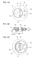
- Fig. 6A shows a top view of a cam member
- Fig. 6B shows a lateral cross section of the cam member
- Fig. 6C shows a bottom view of the cam member
- Fig. 7 is a diagram sterically showing the cam member
- Fig. 8 shows a part of shear blades of the hedge blade assembly
- Fig. 9 shows the hedge blade assembly attached to a main body
- Fig. 10 shows a state where the hedge blade assembly is removed from the main body
- Fig. 11 shows a fixation screw and a retaining member of the hedge blade assembly
- Fig. 12 is a diagram showing shear blades of the lawn blade assembly
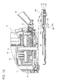
- Fig. 13 shows the lawn blade assembly attached to the main body
- Fig. 14 shows a state where the lawn blade assembly is removed from the main body
- Fig. 15 shows a modified example of the fixation screw and the retaining member of the hedge blade assembly
- Fig. 16 shows the hedge blade assembly of a modified example attached to the main body.
- the diameter of the respective cams can be freely designed in the cam member in accordance with the structure or operation of the corresponding shear blades. Specifically, the diameters of the four cams do not need to be the same, and may be different from one another. However, if the diameters of the four cams are different, then the masses of the four cams will also be different. If the masses of the four cams are different, the balance of the cam member may be spoiled. For addressing this problem, it would be effective to increase the thickness of the cam with a small diameter. Contrarily, the thickness of the cam with a large diameter may be decreased.
- At least one cam among the first, second, third and fourth cams it is preferable to design at least one cam among the first, second, third and fourth cams to have a smaller diameter and greater thickness in comparison to at least one of the other cams.
- the main body comprises a rotation member configured to be rotatably driven by the prime mover.
- the cam member may be coaxially fixed to an end face of the rotation member in a first arrangement in which the third and fourth cams face the rotation member when the first type blade assembly is attached to the main body.
- the cam member may be coaxially fixed to the end face of the rotation member in a second arrangement in which the first and second cams face the rotation member when the second type blade assembly is attached to the main body.
- the rotation member may preferably have a recess formed on its end face.
- the rotation member may preferably house the third cam and the fourth cam in the recess when the cam member is fixed to the rotation member in the first arrangement.
- the rotation member may preferably house the first cam and the second cam in the recess when the cam member is fixed to the rotation member in the second arrangement. According to this structure, the two cams that are not used are housed in the recess of the rotation member and the space required for disposing the cam member can be reduced.
- a thin-walled portion is partly formed in at least one of the first, second, third and fourth cams.
- the mass of that cam can be adjusted. Accordingly, by selectively forming a thin-walled portion on one or more of the four cams and adjusting the mass of the respective cams, the overall mass balance of the cam member can be finely adjusted.
- the first type blade assembly is a hedge blade assembly that is primarily used for trimming hedges
- the second type blade assembly is a lawn blade assembly that is primarily used for trimming lawn.
- the hedge blade assembly is not limited to trimming the hedges, and may also be used for trimming other trees.
- the lawn blade assembly is not limited to trimming the lawn, and may also be used for trimming other plants.
- the pair of shear blades of the blade assembly is supported in a slidable or swingable manner.
- the base end part of the respective shear blades is provided with an engaging hole to which a corresponding cam of the cam member is engaged.
- the engaging hole is formed in an oval shape, and its long diameter direction is orthogonal to the direction in which the shear blades slide or swing. Consequently, the respective shear blades are configured to reciprocate pursuant to the rotation of the cam member.
- the first and second cams can be arranged at opposite sides of each other with respect to a rotation center of the cam member, and the third and fourth cams can be arranged at opposite sides of each other with respect to the rotation center of the cam member.
- one of the first and second cams and one of the third and fourth cams can be arranged at a same side with respect to the rotation center of the cam member, and the other of the first and second cams and the other of the third and fourth cams can be arranged at a same side with respect to the rotation center of the cam member.
- the first and second cams can be arranged at the opposite sides of each other with respect to the rotation center of the cam member, and the third and fourth cams can be arranged at the opposite sides of each other with respect to the rotation center of the cam member. Moreover, the first, second, third and fourth cams can be arranged equiangularly along a circumferential direction.
- the cam member may comprise the four cams; namely, the first, second, third and fourth cams, and a plate member.
- the first and second cams are provided to one side of the plate member, and the third and fourth cams are provided to the other side of the plate member.
- the plate member will come in contact with the end face of the rotation member and stabilize the cam member regardless of whether the cam member is attached to the rotation member in the first arrangement or the second arrangement.
- a linear groove that extends in a straight line may be formed at the head part of the fixation screw.
- a coin-shaped member can be inserted into the linear groove, and the user can use the coin-shaped member and easily rotate the fixation screw.
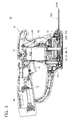
- Fig. 1 and Fig. 2 show the external view of the gardening trimmer 10.
- the gardening trimmer 10 comprises a main body 12 shown in Fig. 1 and Fig. 2 , a hedge blade assembly 100 shown in Fig. 1 , and a lawn blade assembly 200 shown in Fig. 2 .
- the blade assemblies 100, 200 can be replaced according to the work involved, and the hedge blade assembly 100 can be used upon trimming hedges and the lawn blade assembly 200 can be used upon trimming lawns.
- the hedge blade assembly 100 comprises a pair of shear blades 110, and a lower plate 120 and an upper plate 130 for retaining the pair of shear blades 110.
- the pair of shear blades 110 is slidably supported by being sandwiched between the lower plate 120 and the upper plate 130.
- Each of the shear blades 110 is formed with blade edges 112 arranged in a comb-like shape along a sliding direction of the blades.
- the pair of shear blades 110 cuts the branches and leaves of the hedges with its blade edge 112 by relatively reciprocating.
- the hedge blade assembly 100 is provided with two fixation screws 140 for fixing the hedge blade assembly 100 to the main body 12.
- the fixation screws 140 fix the hedge blade assembly 100 to the main body 12 by being screwed into the main body 12.
- the main body 12 is provided with two nuts 72 for receiving the fixation screws 140 respectively.
- the hedge blade assembly 100 is fixed to the main body 12 not only with the fixation screws 140, but also by being retained with a bottom cover 30 described later.
- the lawn blade assembly 200 comprises a pair of shear blades 210, and a lower plate 220 and a support pin 230 for retaining the pair of shear blades 210.
- the pair of shear blades 210 is fixed to the lower plate 220 by a support pin 230, and is supported in a swingable manner.
- the respective shear blades 210 are each formed with blade edges 212 arranged in a comb-liked shape along a swing direction of the blades.
- the pair of shear blades 210 cuts the lawn with its blade edges 212 by relatively reciprocating.
- fixation screws 140 are not provided to the lawn blade assembly 200 as with the hedge blade assembly 100. Since the lawn blade assembly 200 is shorter than the hedge blade assembly 100, it can be firmly fixed to the main body 12 only with the bottom cover 30 described later.
- the main body 12 comprises a housing 14.
- the housing 14 is provided with a trigger 16 as an activation switch, a grip part 18 to be gripped by a user, a battery pack 20 as a power source, a chip guard 22 for preventing the scattering of chips, and so on.
- a trigger 16 as an activation switch
- a grip part 18 to be gripped by a user
- a battery pack 20 as a power source
- a chip guard 22 for preventing the scattering of chips, and so on.
- the bottom part of the housing 14 is formed with an opening 24 to which the blade assemblies 100, 200 are attached.
- the hedge blade assembly 100 and the lawn blade assembly 200 can be detachably attached to the opening 24 of the housing 14.
- a bottom cover 30 is attached to the opening 24 of the housing 14 after the blade assemblies 100, 200 are attached.
- the fixation screws 140 are tightened before attaching the bottom cover 30.
- the fixation screws 140 can each be tightened or loosened with a coin or a coin-shaped member without requiring a tool such as a screw driver.
- Fig. 3 shows the bottom cover 30.
- the bottom cover 30 is provided with claw parts 32 at four locations for engaging with the housing 14, and blade supporting parts 34 at three locations for supporting the blade assemblies 100, 200.
- the bottom cover 30 is rotated in one direction relative to the housing 14 in a state where the bottom cover 30 is fitted into the opening 24 of the housing 14. Consequently, the claw parts 32 at the four locations of the bottom cover 30 are engaged with the housing 14, and the bottom cover 30 is fixed to the housing 14.
- the blade supporting parts 34 of the bottom cover 30 come in contact with the blade assemblies 100, 200 attached to the main body 12.
- the blade supporting parts 34 are each formed with an inclined surface 34a, and the blade assemblies 100, 200 are thereby fixed at a proper position.
- the bottom cover 30 when removing the bottom cover 30, the bottom cover 30 is rotated in the opposite direction relative to the housing 14. Consequently, the engagement of the claw parts 32 of the bottom cover 30 and the housing 14 will be released.
- a tool such as the screw driver is not required for the attachment and detachment of the bottom cover 30.
- the blade assemblies 100, 200 can be replaced with one another without having to use a tool.
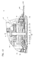
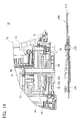
- Fig. 4 and Fig. 5 are cross sections showing the internal structure of the gardening trimmer 10.
- Fig. 4 shows a state where the hedge blade assembly 100 is attached
- Fig. 4 shows a state where the lawn blade assembly 200 is attached.
- the main body 12 comprises a motor 40 as a prime mover of the gardening trimmer 10, a motor pinion 42 provided to the motor 40, a double gear 44 engaged with the motor pinion 42, and a final gear 50 engaged with the double gear 44.
- a recess 52 for partially housing the cam member 60 described later is formed at the end face on the lower side of the final gear 50.
- the motor 40 is electrically connected to the battery pack 20 via the trigger 16. When the user operates the trigger 16, the motor 40 is rotated by the power from the battery pack 20. When the motor 40 is rotated, the final gear 50 is rotatably driven via the motor pinion 42 and the double gear 44. The final gear 50 is supported by a shaft 70, and rotates around the shaft 70. As described above, the final gear 50 is a rotation member that is rotatably driven by the motor 40.
- the cam member 60 is fixed to the end face of the lower side of the final gear 50 in a manner such that relative rotation is not possible.
- the cam member 60 is coaxially fixed to the final gear 50, and rotates together with the final gear 50 around the shaft 70.
- the cam member 60 is rotatably driven together with the final gear 50 by the motor 40.
- the end face of the lower side of the final gear 50 is provided with two connecting pins 54 for retaining the cam member 60 such that the relative rotation is not possible (not shown in Fig. 4 and Fig. 5 ).
- the cam member 60 can be attached to and detached from the final gear 50, and the cam member 60 can be removed from the final gear 50 by removing the blade assemblies 100, 200 from the main body 12.
- the cam member 60 is connected to the pair of shear blades 110 or 210 of the blade assembly 100 or 200 attached to the main body 12.
- the cam member 60 reciprocates the connected pair of shear blades 110 or 210 by being rotated.
- the pair of shear blades 110 or 210 reciprocates with a mutual phase difference of 180 degrees.
- the cam member 60 is attached to the final gear 50 in an opposite arrangement between when the hedge blade assembly 100 is attached to the main body 12 and when the lawn blade assembly 200 is attached to the main body 12.
- the cam member 60 comprises four cams; namely, a first cam 61, a second cam 62, a third cam 63, and a fourth cam 64.
- the first cam 61 and the second cam 62 are cams to be connected to the pair of shear blades 110 of the hedge blade assembly 100
- the third cam 63 and the fourth cam 64 are cams to be connected to the pair of shear blades 210 of the lawn blade assembly 200.
- Each of the cams 61, 62, 63, 64 is formed in a discoid shape, and laminated in the order of the first cam 61, the second cam 62, the third cam 63, and the fourth cam 64.
- an intermediate plate 65 as a disk member is provided between the second cam 62 and the third cam 63.
- the cam member 60 is formed with a central hole 66 for receiving the shaft 70 of the main body 12, and a pin insertion hole 67 for receiving the connecting pin 54 of the final gear 50. Accordingly, the position of the central hole 66 shows the rotational center of the cam member 60.
- the four cams 61, 62, 63, 64 and the intermediate plate 65 are mutually linked with two coupling pins 68.
- the first cam 61 and the second cam 62 are mutually offset in the opposite direction relative to the central hole 66.
- the third cam 63 and the fourth cam 64 are mutually offset in the opposite direction relative to the central hole 66. Accordingly, two cams each are disposed in mutually opposite directions relative to the central hole 66 in the cam member 60. The mass balance of the cam member 60 is thereby maintained. Since the mass balance of the cam member 60 is favorable, the generation of undesirable vibration and noise during the operation of the gardening trimmer 10 can be inhibited.
- the direction of offsetting the first cam 61 and the second cam 62 relative to the central hole 66 and the direction of offsetting the third cam 63 and the fourth cam 64 relative to the central hole 66 can be designed to be orthogonal with respect to each other. In this case also, since the four cams will be disposed in 90-degrees intervals relative to the central hole 66, the mass balance of the cam member 60 is maintained.
- the four cams 61, 62, 63, 64 are individually designed as to their respective diameter and offset distance from the central hole 66 so that each may be appropriately designed for its corresponding pair of shear blades 110, 210.
- the first cam 61 and the second cam 62 have the same diameter, and the offset distance from the central hole 66 is also the same.
- the third cam 63 and the fourth cam 64 have diameters differing from one another, but the offset distance from the central hole 66 is the same.
- the diameter D4 of the fourth cam 64 is especially small in comparison to that of the other three cams 61, 62, 63.
- the thickness D4 of the fourth cam 64 having the smaller diameter is made to be greater than the thickness of the third cam 63 having a greater diameter. Consequently, the mass difference between the third cam 63 and the fourth cam 64 is reduced, and the mass balance of the cam member 60 is thereby improved.
- the thickness should be made smaller for a cam having larger diameter, and also, the thickness should be made smaller for a cam having greater offset distance.
- a thin-walled portion (depression) 61a, 64a is formed on a part of the respective surface of the first cam 61 and the fourth cam 64.
- the masses of the first cam 61 and the fourth cam 64 are finely adjusted with the thin-walled portions 61a, 64a.
- the shape of the thin-walled portions (depressions) 61a, 64a should be a shape into which a person's finger will fit. The operator will thereby be able to easily adjust the direction of the cam member 60 by placing his/her finger on the thin-walled portion (depression) 61a, 64a upon replacing the blade assemblies 100, 200.
- Fig. 8 shows the pair of shear blades 110 of the hedge blade assembly 100 together with the cam member 60.
- Fig. 9 shows the hedge blade assembly 100 attached to the main body 12. Foremost, the mode of connecting the cam member 60 and the pair of shear blades 110 of the hedge blade assembly 100 will be explained.
- each of the base end parts 114 of the respective shear blades 100 of the hedge blade assembly 100 is formed with an engaging hole 116 for engaging with the cam member 60.
- the cam member 60 is fixed to the final gear 50 in a first arrangement where the third cam 63 and the fourth cam 64 are positioned on the side of the final gear 50. Consequently, in the case of the hedge blade assembly 100, the first cam 61 engages with the engaging hole 116 of the shear blades 110 positioned at the lower side, and the second cam 62 engages with the engaging hole 116 of the shear blade 110 positioned at the upper side.
- the cam member 60 is rotatably driven in the foregoing state, the pair of shear blades 110 will reciprocate so as to move forward and backward relative to the main body 12.
- the third cam 63 and the fourth cam 64 are not used.
- the unused third cam 63 and fourth cam 64 are housed in the recess 52 of the final gear 50.
- the cam member 60 of this embodiment includes four cams 61, 62, 63, 64, and its size is relatively large. Accordingly, by adopting a configuration in which the unused third cam 63 and fourth cam 64 are housed internally of the final gear 50, the space that is required for disposing the cam member 60 can be reduced.
- the intermediate plate 65 of the cam member 60 comes in contact with the end face of the lower side of the final gear 50 so as to stabilize the posture relative to the final gear 50 of the cam member 60.
- the generation of undesirable vibration and noise during the operation can thereby be inhibited.
- the posture of the cam member 60 relative to the final gear 50 is extremely stable as a result of the entire periphery of the intermediate plate 65 coming in contact with the final gear 50.
- Fig. 10 shows a state in which the hedge blade assembly 100 is removed from the main body 12.
- the bottom cover 30 is foremost removed (not shown in Fig. 10 ), and the fixation screws 140 are subsequently loosened.
- the hedge blade assembly 100 can thereby be removed downward.
- the cam member 60 is removed from the main body 12 together with the hedge blade assembly 100.
- the hedge blade assembly 100 is formed with a bending part 122 at a part thereof so that the lower plate 120 will not interfere with the housing 14.
- the bending part 122 engages with a part of the main body 12, and is an engagement protrusion for performing the positioning in the horizontal direction.
- the fixation screw 140 positioned in the front side the bending part 122 positioned rearward will also be engaged with the main body 12, and the hedge blade assembly 100 will thereby be fixed firmly. Moreover, the positioning during the assembly can also be easily performed by the bending part 122 being elongated upward.
- the hedge blade assembly 100 is provided with a retaining member 150 relative to the respective fixation screws 140.
- Each of the retaining members 150 has a through-hole 152 for passing the fixation screw 140 therethrough. The retaining members 150 prevent the fixation screw 140 from falling when the hedge blade assembly 100 is removed from the main body 12.
- the fixation screw 140 comprises a head part 142 and a shaft part 144.
- the shaft part 144 is formed with a thin diameter portion 146 and a screw portion 148.
- the screw portion 148 is screwed into the corresponding nut 72 of the main body 12.
- the thin diameter portion 146 is positioned toward the side of the head part 142 than the screw portion 148, and its outer diameter is smaller than the outer diameter of the screw portion 148.
- the through-hole 152 of the retaining member 150 is formed with a small diameter portion 154 and a large diameter portion 156.
- the small diameter portion 154 is engraved with an internal thread of a size corresponding to the screw portion 148 of the fixation screw 140.
- the inner diameter of the small diameter portion 154 is smaller than the outer diameter of the screw portion 148 of the fixation screw 140. Accordingly, the screw portion 148 of the fixation screw 140 is unable to directly pass the small diameter portion 154 therethrough. The fixation screw 140 is thereby prevented from falling.
- the fixation screw 140 can be rotated in order to remove the fixation screw 140 from the hedge blade assembly 100.
- each retaining member 150 comes in contact with both the hedge blade assembly 100 and the nut 72 of the main body 12 in a state where the hedge blade assembly 100 is attached to the main body 12. Consequently, even if the fixation screw 140 is tightened firmly, it is possible to prevent the hedge blade assembly 100 from warping. In a state where the hedge blade assembly 100 is warped, a heavy load is applied to the reciprocating pair of shear blades 102, and problems such as abnormal heat generation and damage of the hedge blade assembly 100 may occur.
- the retaining members 150 of this embodiment do not simply prevent the deformation of the hedge blade assembly 100, but also prevent problems such as abnormal heat generation and damage of the hedge blade assembly 100 that may occur due to its deformation.
- the respective screw portion 148 of the fixation screw 140 will interfere with the retaining member 150 upon tightening or loosening the fixation screw 140. If the screw portions 148 of the fixation screws 140 interfere with the retaining members 150, the position of the hedge blade assembly 100 will be unstable, and the process of attaching or detaching the blade assembly 100 will become troublesome.
- a large diameter portion 156 is formed at a part of the respective through-hole 152.
- the large diameter portion 156 extends to the tip part on the side of the main body 12, and its inner diameter is greater than the outer diameter of the screw portion 148 of the corresponding fixation screw 140.
- the large diameter portions 156 of this embodiment are each formed to be sufficiently longer than the screw portion 148 of the corresponding fixation screw 140, and configured so that they are able to completely house the screw portion 148 of the fixation screw 140.
- the fixation screws 140 can be tightened and loosened without having to use a tool such as a screw driver.
- a linear groove 142a that extends in a straight line is formed at the head part 142 of each fixation screw 140, and a coin-shaped member such as a coin or a medal can be inserted into the linear groove 142a.
- the shape of the linear groove 142a is also shown in Fig. 1 . According to this configuration, the user is able to tighten or loosen the fixation screw 140 with a coin or the like in hand without having to carry around a tool such as a screw driver. Consequently, with the gardening trimmer 10 of this embodiment, a tool is not required upon replacing the blade assemblies 100, 200.
- an engaging hole 216 for engaging with the cam member 60 is formed at the base end part 214 of the respective shear blades 210 of the lawn blade assembly 200.
- the cam member 60 is fixed to the final gear 50 in a second arrangement where the first cam 61 and the second cam 62 are positioned on the side of the final gear 50. Consequently, in the case of the lawn blade assembly 200, the fourth cam 64 engages with the engaging hole 216 of the shear blade 210 positioned at the lower side and the third cam 63 engages with the engaging hole 216 of the shear blade 210 positioned at the upper side.
- the first cam 61 and the second cam 62 are not used and these are housed in the recess 52 of the final gear 50.
- the recess 52 of the final gear 50 is formed with a housing portion 52a corresponding to the shape of the first cam 61 and the second cam 62, and a housing portion 52b corresponding to the shape of the third cam 63 and the fourth cam 64. Consequently, even if the first cam 61 and the second cam 62 are housed in the recess 52 of the final gear 50, the intermediate plate 65 of the cam member 60 will come in contact with the end face at the lower side of the final gear 50. Regardless of the arrangements of the cam member 60, the cam member 60 is stably fixed to the final gear 50.
- Fig. 14 shows a state where the lawn blade assembly 200 is removed from the main body 12.
- the lawn blade assembly 200 can be removed downward simply by removing the bottom cover 30 (not shown in Fig. 14 ).
- the lawn blade assembly 200 can be removed with the cam member 60 still fixed to the final gear 50.
- cams are provided to the cam member 60, and these cams are disposed in a well balanced manner.
- the mass balance of the cam member 60 is favorably maintained.
- the thickness of the cam is adjusted according to its diameter, and the thin-walled portion is selectively formed as needed.
- the mass balance of the cam member 60 is further improved. According to these structures, the generation of undesirable vibration and noise can be inhibited upon operating the gardening trimmer 10.
- the fixation screw 160 comprises a head part 162 and a shaft part 164.
- the head part 162 is similarly formed with a linear groove 162a.
- the shaft part 164 is similarly formed with a thin diameter portion 166 and a screw portion 168.
- the retaining member 170 is shorter than the retaining member 150 explained above.
- a through-hole 172 of the retaining member 170 is engraved with an internal thread of a size corresponding to the screw portion 168 of the fixation screw 160, and its inner diameter is smaller than the outer diameter of the screw portion 168.
- the fixation screw 160 is thereby prevented from falling.
- the fixation screw 160 can be rotated in order to remove the fixation screw 160 from the hedge blade assembly 100.
- Fig. 16 shows a state where the hedge blade assembly 100 is attached to the main body 12 using the fixation screw 160 and the retaining member 170 of the modified example.
- the retaining member 170 of the modified example has a simple structure, and can also be configured from a general-purpose nut or the like.
Abstract
Description
- The present invention relates to a gardening trimmer, particularly relates to a gardening trimmer capable of using two types of blade assemblies.
- As disclosed in Japanese Patent Application Publication No.
2005-341885 2007-151437 - The cam member is provided with three cams; namely, first, second and third cams. With this kind of gardening trimmer, when the first type blade assembly is attached to the main body, the first and second cams are connected to that pair of shear blades, and when the second type blade assembly is attached to the main body replacing the first type blade assembly, the second and third cams are connected to those shear blades.
- With this gardening trimmer, a single cam member is commonly used for the two types of blade assemblies. According to this structure, it is not necessary to prepare an exclusive cam member for each type of blade assembly. In addition, since a single cam (second cam) is commonly used between the two types of blade assemblies, the number of cams to be provided to the cam member can be reduced.
- Nevertheless, in the foregoing gardening trimmer, it is difficult to dispose the three cams in the cam member in a balanced manner. The reason for this is because the first and second cams need to be disposed on the opposite sides of each other with respect to the rotation axis of the cam member. In addition, the second and third cams need to be mutually offset in the opposite direction with respect to the rotation axis of the cam member. Consequently, among the three cam members, two cams, namely the first and third cams, are disposed in the same direction with respect to the rotation axis of the cam member. With this structure, the center of gravity of the cam member may be biased toward one direction with respect to the rotation axis. An ill-balanced cam member will generate undesirable vibration and noise when it is rotatably driven by a motor.
- It is an object of the present teachings to improve a balance of a cam member of a gardening trimmer configured capable of using two types of blade assemblies.
- In a preferable embodiment of the present teachings, a gardening trimmer comprises a main body, a prime mover and a cam member disposed in the main body, a first type blade assembly, and a second type blade assembly. Each of the first and second type blade assemblies comprises a pair of shear blades and is configured to be detachably attached to the main body in substitute of the other. The cam member is configured to be rotatably driven by the prime mover and causes the pair of shear blades of the first or second type blade assembly attached to the main body to reciprocate.
- The cam member preferably comprises four cams including a first cam, a second cam, a third cam and a fourth cam. The first and second cams are configured to be connected with the pair of shear blades of the first type blade assembly when the first type blade assembly is attached to the main body. The third and fourth cams are configured to be connected with the pair of shear blades of the second type blade assembly when the second type blade assembly is attached to the main body.
- In this gardening trimmer, the four cams; namely, the first, second, third and fourth cams are provided to the cam member. The first and second cams may be disposed on the opposite sides of each other with respect to the rotation axis of the cam member. The third and fourth cams may be disposed on the opposite sides of each other with respect to the rotation axis of the cam member. According to this arrangement, the weights of the first and second cams will be negated by each other, and the weights of the third and fourth cams will be negated by each other. Consequently, the balance of the cam member is improved and the generation of undesirable vibration and noise may be avoided.
-
Fig. 1 shows a gardening trimmer of an embodiment together with a hedge blade assembly; -
Fig. 2 shows the gardening trimmer of an embodiment together with a lawn blade assembly; -
Fig. 3 shows a bottom cover; -
Fig. 4 shows a cross section of the gardening trimmer attached with the hedge blade assembly; -
Fig. 5 shows a cross section of the gardening trimmer attached with the lawn blade assembly; -
Fig. 6A shows a top view of a cam member,Fig. 6B shows a lateral cross section of the cam member, andFig. 6C shows a bottom view of the cam member; -
Fig. 7 is a diagram sterically showing the cam member; -
Fig. 8 shows a part of shear blades of the hedge blade assembly; -
Fig. 9 shows the hedge blade assembly attached to a main body; -
Fig. 10 shows a state where the hedge blade assembly is removed from the main body; -
Fig. 11 shows a fixation screw and a retaining member of the hedge blade assembly; -
Fig. 12 is a diagram showing shear blades of the lawn blade assembly; -
Fig. 13 shows the lawn blade assembly attached to the main body; -
Fig. 14 shows a state where the lawn blade assembly is removed from the main body; -
Fig. 15 shows a modified example of the fixation screw and the retaining member of the hedge blade assembly; and -
Fig. 16 shows the hedge blade assembly of a modified example attached to the main body. - In embodiments of the present teachings, the diameter of the respective cams can be freely designed in the cam member in accordance with the structure or operation of the corresponding shear blades. Specifically, the diameters of the four cams do not need to be the same, and may be different from one another. However, if the diameters of the four cams are different, then the masses of the four cams will also be different. If the masses of the four cams are different, the balance of the cam member may be spoiled. For addressing this problem, it would be effective to increase the thickness of the cam with a small diameter. Contrarily, the thickness of the cam with a large diameter may be decreased.
- In an aspect of the above-mentioned teachings, it is preferable to design at least one cam among the first, second, third and fourth cams to have a smaller diameter and greater thickness in comparison to at least one of the other cams.
- In one embodiment of the present teachings, preferably, the main body comprises a rotation member configured to be rotatably driven by the prime mover. In this case, the cam member may be coaxially fixed to an end face of the rotation member in a first arrangement in which the third and fourth cams face the rotation member when the first type blade assembly is attached to the main body. Moreover, the cam member may be coaxially fixed to the end face of the rotation member in a second arrangement in which the first and second cams face the rotation member when the second type blade assembly is attached to the main body.
- When the four cams are provided in the cam member, the size of the cam member will increase and the space required for disposing the cam member will also expand. Thus, in one embodiment of the present teachings, the rotation member may preferably have a recess formed on its end face. In this case, the rotation member may preferably house the third cam and the fourth cam in the recess when the cam member is fixed to the rotation member in the first arrangement. Moreover, the rotation member may preferably house the first cam and the second cam in the recess when the cam member is fixed to the rotation member in the second arrangement. According to this structure, the two cams that are not used are housed in the recess of the rotation member and the space required for disposing the cam member can be reduced.
- In one embodiment of the present teachings, it is preferable that a thin-walled portion is partly formed in at least one of the first, second, third and fourth cams. By forming a thin-walled portion in the cam, the mass of that cam can be adjusted. Accordingly, by selectively forming a thin-walled portion on one or more of the four cams and adjusting the mass of the respective cams, the overall mass balance of the cam member can be finely adjusted.
- In one embodiment of the present teachings, the first type blade assembly is a hedge blade assembly that is primarily used for trimming hedges, and the second type blade assembly is a lawn blade assembly that is primarily used for trimming lawn. Nevertheless, the hedge blade assembly is not limited to trimming the hedges, and may also be used for trimming other trees. Similarly, the lawn blade assembly is not limited to trimming the lawn, and may also be used for trimming other plants.
- In one embodiment of the present teachings, the pair of shear blades of the blade assembly is supported in a slidable or swingable manner. The base end part of the respective shear blades is provided with an engaging hole to which a corresponding cam of the cam member is engaged. The engaging hole is formed in an oval shape, and its long diameter direction is orthogonal to the direction in which the shear blades slide or swing. Consequently, the respective shear blades are configured to reciprocate pursuant to the rotation of the cam member.
- In one embodiment of the present teachings, the first and second cams can be arranged at opposite sides of each other with respect to a rotation center of the cam member, and the third and fourth cams can be arranged at opposite sides of each other with respect to the rotation center of the cam member. Moreover, one of the first and second cams and one of the third and fourth cams can be arranged at a same side with respect to the rotation center of the cam member, and the other of the first and second cams and the other of the third and fourth cams can be arranged at a same side with respect to the rotation center of the cam member.
- In one embodiment of the present teachings, the first and second cams can be arranged at the opposite sides of each other with respect to the rotation center of the cam member, and the third and fourth cams can be arranged at the opposite sides of each other with respect to the rotation center of the cam member. Moreover, the first, second, third and fourth cams can be arranged equiangularly along a circumferential direction.
- In one embodiment of the present teachings, the cam member may comprise the four cams; namely, the first, second, third and fourth cams, and a plate member. The first and second cams are provided to one side of the plate member, and the third and fourth cams are provided to the other side of the plate member. The plate member will come in contact with the end face of the rotation member and stabilize the cam member regardless of whether the cam member is attached to the rotation member in the first arrangement or the second arrangement.
- In one embodiment of the present teachings, a linear groove that extends in a straight line may be formed at the head part of the fixation screw. A coin-shaped member can be inserted into the linear groove, and the user can use the coin-shaped member and easily rotate the fixation screw.
- The gardening
trimmer 10 of an embodiment of this invention is now explained with reference to the attached drawings.Fig. 1 andFig. 2 show the external view of thegardening trimmer 10. The gardeningtrimmer 10 comprises amain body 12 shown inFig. 1 andFig. 2 , ahedge blade assembly 100 shown inFig. 1 , and alawn blade assembly 200 shown inFig. 2 . With thegardening trimmer 10, theblade assemblies hedge blade assembly 100 can be used upon trimming hedges and thelawn blade assembly 200 can be used upon trimming lawns. - The
respective blade assemblies Fig. 1 , thehedge blade assembly 100 comprises a pair ofshear blades 110, and alower plate 120 and anupper plate 130 for retaining the pair ofshear blades 110. The pair ofshear blades 110 is slidably supported by being sandwiched between thelower plate 120 and theupper plate 130. Each of theshear blades 110 is formed withblade edges 112 arranged in a comb-like shape along a sliding direction of the blades. The pair ofshear blades 110 cuts the branches and leaves of the hedges with itsblade edge 112 by relatively reciprocating. - Moreover, the
hedge blade assembly 100 is provided with twofixation screws 140 for fixing thehedge blade assembly 100 to themain body 12. The fixation screws 140 fix thehedge blade assembly 100 to themain body 12 by being screwed into themain body 12. Themain body 12 is provided with twonuts 72 for receiving the fixation screws 140 respectively. Thehedge blade assembly 100 is fixed to themain body 12 not only with the fixation screws 140, but also by being retained with abottom cover 30 described later. - As shown in
Fig. 2 , thelawn blade assembly 200 comprises a pair ofshear blades 210, and alower plate 220 and asupport pin 230 for retaining the pair ofshear blades 210. The pair ofshear blades 210 is fixed to thelower plate 220 by asupport pin 230, and is supported in a swingable manner. Therespective shear blades 210 are each formed withblade edges 212 arranged in a comb-liked shape along a swing direction of the blades. The pair ofshear blades 210 cuts the lawn with its blade edges 212 by relatively reciprocating. - Note that the fixation screws 140 are not provided to the
lawn blade assembly 200 as with thehedge blade assembly 100. Since thelawn blade assembly 200 is shorter than thehedge blade assembly 100, it can be firmly fixed to themain body 12 only with thebottom cover 30 described later. - The
main body 12 is now explained. As shown inFig. 1 andFig. 2 , themain body 12 comprises ahousing 14. Thehousing 14 is provided with atrigger 16 as an activation switch, agrip part 18 to be gripped by a user, abattery pack 20 as a power source, achip guard 22 for preventing the scattering of chips, and so on. Hereinbelow, unless specifically explained independently, a collective description will be given regarding the attachment and detachment of theblade assemblies blade assemblies main body 12" may be used hereinbelow, but it should be noted that such is merely a collective expression, and is intended to mean that theblade assembly 100 can be attached to themain body 12 and theblade assembly 200 can be attached to themain body 12. It is not intended to mean that theblade assemblies main body 12. In a similar manner, expression such as "thecam member 60 is connected to the pair ofshear blades blade assemblies cam member 60 can be connected to the pair ofshear blades - The bottom part of the
housing 14 is formed with anopening 24 to which theblade assemblies hedge blade assembly 100 and thelawn blade assembly 200 can be detachably attached to theopening 24 of thehousing 14. Abottom cover 30 is attached to theopening 24 of thehousing 14 after theblade assemblies hedge blade assembly 100, the fixation screws 140 are tightened before attaching thebottom cover 30. As will be described in detail later, the fixation screws 140 can each be tightened or loosened with a coin or a coin-shaped member without requiring a tool such as a screw driver. -
Fig. 3 shows thebottom cover 30. Thebottom cover 30 is provided withclaw parts 32 at four locations for engaging with thehousing 14, andblade supporting parts 34 at three locations for supporting theblade assemblies bottom cover 30 is attached, thebottom cover 30 is rotated in one direction relative to thehousing 14 in a state where thebottom cover 30 is fitted into theopening 24 of thehousing 14. Consequently, theclaw parts 32 at the four locations of thebottom cover 30 are engaged with thehousing 14, and thebottom cover 30 is fixed to thehousing 14. When thebottom cover 30 is fixed to thehousing 14, theblade supporting parts 34 of thebottom cover 30 come in contact with theblade assemblies main body 12. Theblade supporting parts 34 are each formed with aninclined surface 34a, and theblade assemblies bottom cover 30, thebottom cover 30 is rotated in the opposite direction relative to thehousing 14. Consequently, the engagement of theclaw parts 32 of thebottom cover 30 and thehousing 14 will be released. A tool such as the screw driver is not required for the attachment and detachment of thebottom cover 30. With thegardening trimmer 10, theblade assemblies - The internal structure of the
main body 12 is now explained.Fig. 4 andFig. 5 are cross sections showing the internal structure of thegardening trimmer 10. Here,Fig. 4 shows a state where thehedge blade assembly 100 is attached, andFig. 4 shows a state where thelawn blade assembly 200 is attached. As shown inFig. 4 andFig. 5 , themain body 12 comprises amotor 40 as a prime mover of thegardening trimmer 10, amotor pinion 42 provided to themotor 40, adouble gear 44 engaged with themotor pinion 42, and afinal gear 50 engaged with thedouble gear 44. Arecess 52 for partially housing thecam member 60 described later is formed at the end face on the lower side of thefinal gear 50. - The
motor 40 is electrically connected to thebattery pack 20 via thetrigger 16. When the user operates thetrigger 16, themotor 40 is rotated by the power from thebattery pack 20. When themotor 40 is rotated, thefinal gear 50 is rotatably driven via themotor pinion 42 and thedouble gear 44. Thefinal gear 50 is supported by ashaft 70, and rotates around theshaft 70. As described above, thefinal gear 50 is a rotation member that is rotatably driven by themotor 40. - The
cam member 60 is fixed to the end face of the lower side of thefinal gear 50 in a manner such that relative rotation is not possible. Thecam member 60 is coaxially fixed to thefinal gear 50, and rotates together with thefinal gear 50 around theshaft 70. Specifically, thecam member 60 is rotatably driven together with thefinal gear 50 by themotor 40. As shown inFig. 1 , the end face of the lower side of thefinal gear 50 is provided with two connectingpins 54 for retaining thecam member 60 such that the relative rotation is not possible (not shown inFig. 4 andFig. 5 ). Note that thecam member 60 can be attached to and detached from thefinal gear 50, and thecam member 60 can be removed from thefinal gear 50 by removing theblade assemblies main body 12. - As will be described in detail later, the
cam member 60 is connected to the pair ofshear blades blade assembly main body 12. Thecam member 60 reciprocates the connected pair ofshear blades shear blades cam member 60 is attached to thefinal gear 50 in an opposite arrangement between when thehedge blade assembly 100 is attached to themain body 12 and when thelawn blade assembly 200 is attached to themain body 12. - The structure of the
cam member 60 is now explained in detail with reference toFig. 6 andFig. 7 . As shown inFig. 6 andFig. 7 , thecam member 60 comprises four cams; namely, afirst cam 61, asecond cam 62, athird cam 63, and afourth cam 64. As will be described in detail later, thefirst cam 61 and thesecond cam 62 are cams to be connected to the pair ofshear blades 110 of thehedge blade assembly 100, and thethird cam 63 and thefourth cam 64 are cams to be connected to the pair ofshear blades 210 of thelawn blade assembly 200. - Each of the
cams first cam 61, thesecond cam 62, thethird cam 63, and thefourth cam 64. Moreover, anintermediate plate 65 as a disk member is provided between thesecond cam 62 and thethird cam 63. Thecam member 60 is formed with acentral hole 66 for receiving theshaft 70 of themain body 12, and apin insertion hole 67 for receiving the connectingpin 54 of thefinal gear 50. Accordingly, the position of thecentral hole 66 shows the rotational center of thecam member 60. The fourcams intermediate plate 65 are mutually linked with two coupling pins 68. - The
first cam 61 and thesecond cam 62 are mutually offset in the opposite direction relative to thecentral hole 66. Moreover, thethird cam 63 and thefourth cam 64 are mutually offset in the opposite direction relative to thecentral hole 66. Accordingly, two cams each are disposed in mutually opposite directions relative to thecentral hole 66 in thecam member 60. The mass balance of thecam member 60 is thereby maintained. Since the mass balance of thecam member 60 is favorable, the generation of undesirable vibration and noise during the operation of thegardening trimmer 10 can be inhibited. - As a modified example, the direction of offsetting the
first cam 61 and thesecond cam 62 relative to thecentral hole 66 and the direction of offsetting thethird cam 63 and thefourth cam 64 relative to thecentral hole 66 can be designed to be orthogonal with respect to each other. In this case also, since the four cams will be disposed in 90-degrees intervals relative to thecentral hole 66, the mass balance of thecam member 60 is maintained. - With the
hedge blade assembly 100 and thelawn blade assembly 200, the direction and amplitude that the pair ofshear blades cams central hole 66 so that each may be appropriately designed for its corresponding pair ofshear blades - In this embodiment, the
first cam 61 and thesecond cam 62 have the same diameter, and the offset distance from thecentral hole 66 is also the same. Meanwhile, thethird cam 63 and thefourth cam 64 have diameters differing from one another, but the offset distance from thecentral hole 66 is the same. In particular, the diameter D4 of thefourth cam 64 is especially small in comparison to that of the other threecams - If the diameters of the
third cam 63 and thefourth cam 64 are not the same, the masses of thethird cam 63 and thefourth cam 64 will also be different. Thus, the mass balance of thecam member 60 may be failed. Thus, in this embodiment, the thickness D4 of thefourth cam 64 having the smaller diameter is made to be greater than the thickness of thethird cam 63 having a greater diameter. Consequently, the mass difference between thethird cam 63 and thefourth cam 64 is reduced, and the mass balance of thecam member 60 is thereby improved. As described above, by adjusting the thickness of each cam according to the diameter or the offset distance from thecentral hole 66 of each cam, the mass balance of thecam member 60 can be improved. Specifically, the thickness should be made smaller for a cam having larger diameter, and also, the thickness should be made smaller for a cam having greater offset distance. - Moreover, a thin-walled portion (depression) 61a, 64a is formed on a part of the respective surface of the
first cam 61 and thefourth cam 64. The masses of thefirst cam 61 and thefourth cam 64 are finely adjusted with the thin-walled portions cam member 60 can be finely adjusted. Here, the shape of the thin-walled portions (depressions) 61a, 64a should be a shape into which a person's finger will fit. The operator will thereby be able to easily adjust the direction of thecam member 60 by placing his/her finger on the thin-walled portion (depression) 61a, 64a upon replacing theblade assemblies - The connection of the
cam member 60 and the pair ofshear blades Fig. 8 shows the pair ofshear blades 110 of thehedge blade assembly 100 together with thecam member 60.Fig. 9 shows thehedge blade assembly 100 attached to themain body 12. Foremost, the mode of connecting thecam member 60 and the pair ofshear blades 110 of thehedge blade assembly 100 will be explained. - As shown in
Fig. 8 andFig. 9 , each of thebase end parts 114 of therespective shear blades 100 of thehedge blade assembly 100 is formed with anengaging hole 116 for engaging with thecam member 60. When thehedge blade assembly 100 is attached to themain body 12, thecam member 60 is fixed to thefinal gear 50 in a first arrangement where thethird cam 63 and thefourth cam 64 are positioned on the side of thefinal gear 50. Consequently, in the case of thehedge blade assembly 100, thefirst cam 61 engages with the engaginghole 116 of theshear blades 110 positioned at the lower side, and thesecond cam 62 engages with the engaginghole 116 of theshear blade 110 positioned at the upper side. When thecam member 60 is rotatably driven in the foregoing state, the pair ofshear blades 110 will reciprocate so as to move forward and backward relative to themain body 12. - As shown in
Fig. 9 , when thehedge blade assembly 100 is attached to themain body 12, thethird cam 63 and thefourth cam 64 are not used. Thus, the unusedthird cam 63 andfourth cam 64 are housed in therecess 52 of thefinal gear 50. Thecam member 60 of this embodiment includes fourcams third cam 63 andfourth cam 64 are housed internally of thefinal gear 50, the space that is required for disposing thecam member 60 can be reduced. - Moreover, the
intermediate plate 65 of thecam member 60 comes in contact with the end face of the lower side of thefinal gear 50 so as to stabilize the posture relative to thefinal gear 50 of thecam member 60. The generation of undesirable vibration and noise during the operation can thereby be inhibited. In particular, with this embodiment, the posture of thecam member 60 relative to thefinal gear 50 is extremely stable as a result of the entire periphery of theintermediate plate 65 coming in contact with thefinal gear 50. -
Fig. 10 shows a state in which thehedge blade assembly 100 is removed from themain body 12. When thehedge blade assembly 100 is to be removed, thebottom cover 30 is foremost removed (not shown inFig. 10 ), and the fixation screws 140 are subsequently loosened. Thehedge blade assembly 100 can thereby be removed downward. Here, thecam member 60 is removed from themain body 12 together with thehedge blade assembly 100. Thehedge blade assembly 100 is formed with a bendingpart 122 at a part thereof so that thelower plate 120 will not interfere with thehousing 14. The bendingpart 122 engages with a part of themain body 12, and is an engagement protrusion for performing the positioning in the horizontal direction. Consequently, by simply tightening thefixation screw 140 positioned in the front side, the bendingpart 122 positioned rearward will also be engaged with themain body 12, and thehedge blade assembly 100 will thereby be fixed firmly. Moreover, the positioning during the assembly can also be easily performed by the bendingpart 122 being elongated upward. - As shown in
Fig. 10 , thehedge blade assembly 100 is provided with a retainingmember 150 relative to the respective fixation screws 140. Each of the retainingmembers 150 has a through-hole 152 for passing thefixation screw 140 therethrough. The retainingmembers 150 prevent thefixation screw 140 from falling when thehedge blade assembly 100 is removed from themain body 12. - The structure of the
fixation screw 140 and the retainingmember 150 is now explained with reference toFig. 11 . As shown inFig. 11 , thefixation screw 140 comprises ahead part 142 and ashaft part 144. Theshaft part 144 is formed with athin diameter portion 146 and ascrew portion 148. Thescrew portion 148 is screwed into the correspondingnut 72 of themain body 12. Thethin diameter portion 146 is positioned toward the side of thehead part 142 than thescrew portion 148, and its outer diameter is smaller than the outer diameter of thescrew portion 148. - Meanwhile, the through-
hole 152 of the retainingmember 150 is formed with asmall diameter portion 154 and alarge diameter portion 156. Thesmall diameter portion 154 is engraved with an internal thread of a size corresponding to thescrew portion 148 of thefixation screw 140. Here, the inner diameter of thesmall diameter portion 154 is smaller than the outer diameter of thescrew portion 148 of thefixation screw 140. Accordingly, thescrew portion 148 of thefixation screw 140 is unable to directly pass thesmall diameter portion 154 therethrough. Thefixation screw 140 is thereby prevented from falling. In addition, if necessary, thefixation screw 140 can be rotated in order to remove thefixation screw 140 from thehedge blade assembly 100. - As shown in
Fig. 9 , each retainingmember 150 comes in contact with both thehedge blade assembly 100 and thenut 72 of themain body 12 in a state where thehedge blade assembly 100 is attached to themain body 12. Consequently, even if thefixation screw 140 is tightened firmly, it is possible to prevent thehedge blade assembly 100 from warping. In a state where thehedge blade assembly 100 is warped, a heavy load is applied to the reciprocating pair of shear blades 102, and problems such as abnormal heat generation and damage of thehedge blade assembly 100 may occur. The retainingmembers 150 of this embodiment do not simply prevent the deformation of thehedge blade assembly 100, but also prevent problems such as abnormal heat generation and damage of thehedge blade assembly 100 that may occur due to its deformation. - However, if the configuration in which the retaining
member 150 comes in contact with both thehedge blade assembly 100 and the main body 12b is adopted, therespective screw portion 148 of thefixation screw 140 will interfere with the retainingmember 150 upon tightening or loosening thefixation screw 140. If thescrew portions 148 of the fixation screws 140 interfere with the retainingmembers 150, the position of thehedge blade assembly 100 will be unstable, and the process of attaching or detaching theblade assembly 100 will become troublesome. - Thus, with the retaining
member 150 of this embodiment, alarge diameter portion 156 is formed at a part of the respective through-hole 152. As shown inFig. 11 , thelarge diameter portion 156 extends to the tip part on the side of themain body 12, and its inner diameter is greater than the outer diameter of thescrew portion 148 of thecorresponding fixation screw 140. According to this configuration, since thescrew portion 148 of thefixation screw 140 will enter and exit thelarge diameter portion 156 upon tightening and loosening thefixation screw 140, it is possible to prevent thescrew portion 148 from interfering with the retainingmember 150. In particular, thelarge diameter portions 156 of this embodiment are each formed to be sufficiently longer than thescrew portion 148 of thecorresponding fixation screw 140, and configured so that they are able to completely house thescrew portion 148 of thefixation screw 140. - In this embodiment, as described above, the fixation screws 140 can be tightened and loosened without having to use a tool such as a screw driver. Specifically, a
linear groove 142a that extends in a straight line is formed at thehead part 142 of eachfixation screw 140, and a coin-shaped member such as a coin or a medal can be inserted into thelinear groove 142a. The shape of thelinear groove 142a is also shown inFig. 1 . According to this configuration, the user is able to tighten or loosen thefixation screw 140 with a coin or the like in hand without having to carry around a tool such as a screw driver. Consequently, with the gardeningtrimmer 10 of this embodiment, a tool is not required upon replacing theblade assemblies - The mode of connecting the
cam member 60 and the pair ofshear blades 210 of thelawn blade assembly 200 will now be explained. - As shown in
Fig. 12 andFig. 13 , an engaginghole 216 for engaging with thecam member 60 is formed at thebase end part 214 of therespective shear blades 210 of thelawn blade assembly 200. When thelawn blade assembly 200 is attached to themain body 12, thecam member 60 is fixed to thefinal gear 50 in a second arrangement where thefirst cam 61 and thesecond cam 62 are positioned on the side of thefinal gear 50. Consequently, in the case of thelawn blade assembly 200, thefourth cam 64 engages with the engaginghole 216 of theshear blade 210 positioned at the lower side and thethird cam 63 engages with the engaginghole 216 of theshear blade 210 positioned at the upper side. When thecam member 60 is rotatably driven in the foregoing state, the pair ofshear blades 210 will reciprocate in the swinging manner relative to themain body 12. - As shown in
Fig. 13 , when thelawn blade assembly 200 is attached to themain body 12, thefirst cam 61 and thesecond cam 62 are not used and these are housed in therecess 52 of thefinal gear 50. Here, therecess 52 of thefinal gear 50 is formed with ahousing portion 52a corresponding to the shape of thefirst cam 61 and thesecond cam 62, and ahousing portion 52b corresponding to the shape of thethird cam 63 and thefourth cam 64. Consequently, even if thefirst cam 61 and thesecond cam 62 are housed in therecess 52 of thefinal gear 50, theintermediate plate 65 of thecam member 60 will come in contact with the end face at the lower side of thefinal gear 50. Regardless of the arrangements of thecam member 60, thecam member 60 is stably fixed to thefinal gear 50. -
Fig. 14 shows a state where thelawn blade assembly 200 is removed from themain body 12. When removing thelawn blade assembly 200, thelawn blade assembly 200 can be removed downward simply by removing the bottom cover 30 (not shown inFig. 14 ). Thelawn blade assembly 200 can be removed with thecam member 60 still fixed to thefinal gear 50. - As described above, with the gardening
trimmer 10 of this embodiment, four cams are provided to thecam member 60, and these cams are disposed in a well balanced manner. Thus, the mass balance of thecam member 60 is favorably maintained. Moreover, the thickness of the cam is adjusted according to its diameter, and the thin-walled portion is selectively formed as needed. Thus, the mass balance of thecam member 60 is further improved. According to these structures, the generation of undesirable vibration and noise can be inhibited upon operating the gardeningtrimmer 10. - Moreover, with the gardening
trimmer 10 of this embodiment, on the assumption that theblade assemblies hedge blade assembly 100 are taken. In addition, upon exchanging theblade assemblies - Here, the structure of preventing the loss of the fixation screws 140 is shown with a
fixation screw 160 and a retainingmember 170 of a modified example illustrated inFig. 15 andFig. 16 . Thefixation screw 160 comprises ahead part 162 and ashaft part 164. Thehead part 162 is similarly formed with alinear groove 162a. Theshaft part 164 is similarly formed with athin diameter portion 166 and ascrew portion 168. - Meanwhile, the retaining
member 170 is shorter than the retainingmember 150 explained above. A through-hole 172 of the retainingmember 170 is engraved with an internal thread of a size corresponding to thescrew portion 168 of thefixation screw 160, and its inner diameter is smaller than the outer diameter of thescrew portion 168. Thefixation screw 160 is thereby prevented from falling. In addition, if necessary, thefixation screw 160 can be rotated in order to remove thefixation screw 160 from thehedge blade assembly 100. -
Fig. 16 shows a state where thehedge blade assembly 100 is attached to themain body 12 using thefixation screw 160 and the retainingmember 170 of the modified example. As shown inFig. 16 , since the length of the retainingmember 170 has been shortened, a space is formed between thenut 72 and the retainingmember 170, and the retainingmember 170 does not come in contact with thenut 72 but rather comes in contact with another part of themain body 12. As described above, the retainingmember 170 of the modified example has a simple structure, and can also be configured from a general-purpose nut or the like.
It is explicitly stated that all features disclosed in the description and/or the claims are intended to be disclosed separately and independently from each other for the purpose of original disclosure as well as for the purpose of restricting the claimed invention independent of the composition of the features in the embodiments and/or the claims. It is explicitly stated that all value ranges or indications of groups of entities disclose every possible intermediate value or intermediate entity for the purpose of original disclosure as well as for the purpose of restricting the claimed invention, in particular as limits of value ranges.
Claims (9)
- A gardening trimmer (10) comprising:a main body (12);a prime mover (40) disposed in the main body;a first type blade assembly (100) and a second type blade assembly (200), each comprising a pair of shear blades (110, 210) and configured to be detachably attached to the main body in substitute of the other; anda cam member (60) configured to be rotatably driven by the prime mover (40) and causes the pair of shear blades (110, 210) of the first or second type blade assembly (100, 200) attached to the main body to reciprocate;characterized in that:the cam member (60) comprises a first cam (61), a second cam (62), a third cam (63) and a fourth cam (64),the first and second cams (61, 62) are configured to be connected with the pair of shear blades (110) of the first type blade assembly (100) when the first type blade assembly (100) is attached to the main body (12), andthe third and fourth cams (63, 64) are configured to be connected with the pair of shear blades (210) of the second type blade assembly (200) when the second type blade assembly (200) is attached to the main body (12).
- A gardening trimmer (10) as in claim 1, wherein at least one of the first, second, third and fourth cams (61, 62, 63, 64) has a smaller diameter and a greater thickness than at least one of the other cams.
- A gardening trimmer (10) as in claim 1 or 2, wherein
the main body (12) comprises a rotation member (50) configured to be rotatably driven by the prime mover (40),
the cam member (60) is coaxially fixed to an end face of the rotation member (50) in a first arrangement in which the third and fourth cams (63, 64) face the rotation member (50) when the first type blade assembly (100) is attached to the main body (12), and
the cam member (60) is coaxially fixed to the end face of the rotation member (50) in a second arrangement in which the first and second cams (61, 62) face to the rotation member (50) when the second type blade assembly (200) is attached to the main body (12). - A gardening trimmer (10) as in claim 3, wherein the rotation member (50) comprises a recess (52) formed on the end face and is configured to:house the third and fourth cams (63, 64) within the recess (52) when the cam member (60) is fixed to the rotation member (50) in the first arrangement andhouse the first and second cams (61, 62) within the recess (52) when the cam member (60) is fixed to the rotation member in the second arrangement.
- A gardening trimmer (10) as in claim 3 or 4, wherein
the cam member (60) further comprises a plate member (65) configured to contact with the end face of the rotation member (50) when the cam member (60) is fixed to the rotation member (50) in any one of the first and second arrangements. - A gardening trimmer (10) as in any one of claims 1 to 5, wherein a thin-walled portion (61a, 64a) is partly formed in at least one of the first, second, third and fourth cams (61, 62, 63, 64).
- A gardening trimmer (10) as in any one of claims 1 to 6, wherein
the first and second cams (61, 62) are arranged at opposite sides of each other with respect to a rotation center of the cam member (60), and
the third and fourth cams (63, 64) are arranged at opposite sides of each other with respect to the rotation center of the cam member (60). - A gardening trimmer (10) as in claim 7, wherein
one of the first and second cams (61, 62) and one of the third and fourth cams (63, 64) are arranged at a same side with respect to the rotation center of the cam member (60), and
the other of the first and second cams (61, 62) and the other of the third and fourth cams (63, 64) are arranged at a same side with respect to the rotation center of the cam member (60). - A gardening trimmer (10) as in claim 7, wherein the first, second, third and fourth cams (61, 62, 63, 64) are arranged equiangularly with respect to the circumferential direction of the cam member (60).
Applications Claiming Priority (1)
| Application Number | Priority Date | Filing Date | Title |
|---|---|---|---|
| JP2009182746A JP5208878B2 (en) | 2009-08-05 | 2009-08-05 | Gardening hair clipper |
Publications (2)
| Publication Number | Publication Date |
|---|---|
| EP2281440A1 true EP2281440A1 (en) | 2011-02-09 |
| EP2281440B1 EP2281440B1 (en) | 2012-06-27 |
Family
ID=42937366
Family Applications (1)
| Application Number | Title | Priority Date | Filing Date |
|---|---|---|---|
| EP20100170782 Active EP2281440B1 (en) | 2009-08-05 | 2010-07-26 | Gardening trimmer |
Country Status (3)
| Country | Link |
|---|---|
| EP (1) | EP2281440B1 (en) |
| JP (1) | JP5208878B2 (en) |
| CN (1) | CN101990810B (en) |
Cited By (4)
| Publication number | Priority date | Publication date | Assignee | Title |
|---|---|---|---|---|
| US20140007717A1 (en) * | 2012-07-04 | 2014-01-09 | Makita Corporation | Electrically powered gardening tool |
| EP2700298A1 (en) * | 2012-08-20 | 2014-02-26 | Robert Bosch Gmbh | Garden tool insert device |
| EP2965616A1 (en) * | 2014-07-11 | 2016-01-13 | Black & Decker Inc. | Vegetation cutting device |
| WO2019004890A1 (en) * | 2017-06-28 | 2019-01-03 | Husqvarna Ab | Hand-held shears for gardening and method related to hand-held shears |
Families Citing this family (7)
| Publication number | Priority date | Publication date | Assignee | Title |
|---|---|---|---|---|
| JP2015073482A (en) * | 2013-10-09 | 2015-04-20 | 株式会社マキタ | Power transmission device and gardening clipper employing power transmission device |
| CN204180592U (en) * | 2014-10-23 | 2015-03-04 | 常州格力博有限公司 | A kind of integration-in-one new type power source apparatus for pruner |
| CN206024521U (en) * | 2016-08-30 | 2017-03-22 | 株式会社牧田 | An edge -trimmer |
| CN107258212B (en) * | 2017-05-25 | 2020-04-07 | 镇江巨能电气有限公司 | Automatic lawn trimmer |
| JP7253471B2 (en) * | 2019-08-02 | 2023-04-06 | 株式会社やまびこ | Reciprocating cutting blade device and hand-held work machine |
| JP7296819B2 (en) * | 2019-08-08 | 2023-06-23 | 株式会社マキタ | garden trimmer |
| JP7261734B2 (en) * | 2019-12-25 | 2023-04-20 | 株式会社マキタ | garden trimmer |
Citations (4)
| Publication number | Priority date | Publication date | Assignee | Title |
|---|---|---|---|---|
| US3959878A (en) * | 1975-04-02 | 1976-06-01 | Mcgraw-Edison Company | Convertible portable electric tool |
| JP2005341885A (en) | 2004-06-03 | 2005-12-15 | Makita Corp | Hedge trimmer |
| JP2007151437A (en) | 2005-12-02 | 2007-06-21 | Makita Corp | Trimmer |
| DE102009014096A1 (en) * | 2008-03-26 | 2009-10-01 | Positec Power Tools (Suzhou) Co., Ltd. | Motor-driven power-cutting device i.e. grass cutter, for cutting and trimming garden, has connection part including connection arrangement driven by drive device, and another arrangement detachably fastened at former arrangement |
Family Cites Families (4)
| Publication number | Priority date | Publication date | Assignee | Title |
|---|---|---|---|---|
| DE19522971A1 (en) * | 1995-06-28 | 1997-01-02 | Bosch Gmbh Robert | Hedge trimmer |
| JP2000083475A (en) * | 1998-09-09 | 2000-03-28 | Ryobi Ltd | Lawn mower |
| US6901667B2 (en) * | 2003-10-02 | 2005-06-07 | Proulx Manufacturing, Inc. | Trimmer head for use in flexible line rotary trimmers |
| US7513046B2 (en) * | 2003-10-02 | 2009-04-07 | Proulx Manufacturing, Inc. | Trimmer head for use in flexible line rotary trimmers having improved line loading mechanism |
-
2009
- 2009-08-05 JP JP2009182746A patent/JP5208878B2/en active Active
-
2010
- 2010-07-26 EP EP20100170782 patent/EP2281440B1/en active Active
- 2010-08-04 CN CN 201010250281 patent/CN101990810B/en active Active
Patent Citations (4)
| Publication number | Priority date | Publication date | Assignee | Title |
|---|---|---|---|---|
| US3959878A (en) * | 1975-04-02 | 1976-06-01 | Mcgraw-Edison Company | Convertible portable electric tool |
| JP2005341885A (en) | 2004-06-03 | 2005-12-15 | Makita Corp | Hedge trimmer |
| JP2007151437A (en) | 2005-12-02 | 2007-06-21 | Makita Corp | Trimmer |
| DE102009014096A1 (en) * | 2008-03-26 | 2009-10-01 | Positec Power Tools (Suzhou) Co., Ltd. | Motor-driven power-cutting device i.e. grass cutter, for cutting and trimming garden, has connection part including connection arrangement driven by drive device, and another arrangement detachably fastened at former arrangement |
Cited By (7)
| Publication number | Priority date | Publication date | Assignee | Title |
|---|---|---|---|---|
| US20140007717A1 (en) * | 2012-07-04 | 2014-01-09 | Makita Corporation | Electrically powered gardening tool |
| US9357711B2 (en) * | 2012-07-04 | 2016-06-07 | Makita Corporation | Electrically powered gardening tool |
| EP2700298A1 (en) * | 2012-08-20 | 2014-02-26 | Robert Bosch Gmbh | Garden tool insert device |
| EP2965616A1 (en) * | 2014-07-11 | 2016-01-13 | Black & Decker Inc. | Vegetation cutting device |
| US9961839B2 (en) | 2014-07-11 | 2018-05-08 | Black & Decker Inc. | Vegetation cutting device |
| WO2019004890A1 (en) * | 2017-06-28 | 2019-01-03 | Husqvarna Ab | Hand-held shears for gardening and method related to hand-held shears |
| CN110799031A (en) * | 2017-06-28 | 2020-02-14 | 胡斯华纳有限公司 | Hand-held shears for horticulture and methods relating to hand-held shears |
Also Published As
| Publication number | Publication date |
|---|---|
| CN101990810A (en) | 2011-03-30 |
| JP5208878B2 (en) | 2013-06-12 |
| CN101990810B (en) | 2012-12-26 |
| JP2011030542A (en) | 2011-02-17 |
| EP2281440B1 (en) | 2012-06-27 |
Similar Documents
| Publication | Publication Date | Title |
|---|---|---|
| EP2281440B1 (en) | Gardening trimmer | |
| EP2191709A1 (en) | Knife holder for a rotary disk cutterbar | |
| JP5047199B2 (en) | Insert chip and chamfering machine using the same | |
| US9357711B2 (en) | Electrically powered gardening tool | |
| US11464171B2 (en) | Gardening trimmer | |
| US20100122516A1 (en) | Adapter for landscape trimmers | |
| US10327394B2 (en) | Cutting device | |
| JP2021023187A (en) | Reciprocating cutting blade device and handheld work machine | |
| JP5550187B2 (en) | Deburring tool, deburring device and deburring method | |
| EP3756451A1 (en) | Reciprocating blade apparatus and handheld working machine | |
| JP5269715B2 (en) | Gardening hair clipper | |
| US20080301950A1 (en) | Cable cutter with reciprocating cutting wheel for cutting flexible cable | |
| JP7253460B2 (en) | Reciprocating cutting blade device and hand-held work machine | |
| JP3735322B2 (en) | Tillage claw attachment device and forward / reverse rotary tillage device | |
| JP5873776B2 (en) | Gardening hair clipper | |
| JP3217679U (en) | Electric grinder, electric grinder with positioning tool | |
| JP5860781B2 (en) | Blade assembly and hedge trimmer | |
| KR20120100866A (en) | The brush cutter knife and knife operating method and knife operating divice | |
| JP2011045266A (en) | Joint structure of horticultural tool, and horticultural tool equipped with the same | |
| JP6893125B2 (en) | Pruning machine | |
| KR20130040442A (en) | The wire-cutter type device for grass eliminator | |
| JP7284005B2 (en) | Reciprocating cutting blade device | |
| JP4158991B2 (en) | Cutlery for mowing and harvesting rice | |
| CA2523324A1 (en) | Blade for rotary cutter | |
| WO2010015083A1 (en) | Offset guard bolt attachment system |
Legal Events
| Date | Code | Title | Description |
|---|---|---|---|
| PUAI | Public reference made under article 153(3) epc to a published international application that has entered the european phase |
Free format text: ORIGINAL CODE: 0009012 |
|
| AK | Designated contracting states |
Kind code of ref document: A1 Designated state(s): AL AT BE BG CH CY CZ DE DK EE ES FI FR GB GR HR HU IE IS IT LI LT LU LV MC MK MT NL NO PL PT RO SE SI SK SM TR |
|
| AX | Request for extension of the european patent |
Extension state: BA ME RS |
|
| 17P | Request for examination filed |
Effective date: 20110713 |
|
| GRAP | Despatch of communication of intention to grant a patent |
Free format text: ORIGINAL CODE: EPIDOSNIGR1 |
|
| RIN1 | Information on inventor provided before grant (corrected) |
Inventor name: KAMIYA, TAKAHIRO |
|
| GRAS | Grant fee paid |
Free format text: ORIGINAL CODE: EPIDOSNIGR3 |
|
| GRAA | (expected) grant |
Free format text: ORIGINAL CODE: 0009210 |
|
| AK | Designated contracting states |
Kind code of ref document: B1 Designated state(s): AL AT BE BG CH CY CZ DE DK EE ES FI FR GB GR HR HU IE IS IT LI LT LU LV MC MK MT NL NO PL PT RO SE SI SK SM TR |
|
| REG | Reference to a national code |
Ref country code: GB Ref legal event code: FG4D |
|
| REG | Reference to a national code |
Ref country code: CH Ref legal event code: EP |
|
| REG | Reference to a national code |
Ref country code: AT Ref legal event code: REF Ref document number: 563633 Country of ref document: AT Kind code of ref document: T Effective date: 20120715 |
|
| REG | Reference to a national code |
Ref country code: IE Ref legal event code: FG4D |
|
| REG | Reference to a national code |
Ref country code: DE Ref legal event code: R096 Ref document number: 602010002015 Country of ref document: DE Effective date: 20120823 |
|
| PG25 | Lapsed in a contracting state [announced via postgrant information from national office to epo] |
Ref country code: SE Free format text: LAPSE BECAUSE OF FAILURE TO SUBMIT A TRANSLATION OF THE DESCRIPTION OR TO PAY THE FEE WITHIN THE PRESCRIBED TIME-LIMIT Effective date: 20120627 Ref country code: FI Free format text: LAPSE BECAUSE OF FAILURE TO SUBMIT A TRANSLATION OF THE DESCRIPTION OR TO PAY THE FEE WITHIN THE PRESCRIBED TIME-LIMIT Effective date: 20120627 Ref country code: LT Free format text: LAPSE BECAUSE OF FAILURE TO SUBMIT A TRANSLATION OF THE DESCRIPTION OR TO PAY THE FEE WITHIN THE PRESCRIBED TIME-LIMIT Effective date: 20120627 Ref country code: NO Free format text: LAPSE BECAUSE OF FAILURE TO SUBMIT A TRANSLATION OF THE DESCRIPTION OR TO PAY THE FEE WITHIN THE PRESCRIBED TIME-LIMIT Effective date: 20120927 |
|
| REG | Reference to a national code |
Ref country code: NL Ref legal event code: VDEP Effective date: 20120627 |
|
| REG | Reference to a national code |
Ref country code: AT Ref legal event code: MK05 Ref document number: 563633 Country of ref document: AT Kind code of ref document: T Effective date: 20120627 |
|
| REG | Reference to a national code |
Ref country code: LT Ref legal event code: MG4D Effective date: 20120627 |
|
| PG25 | Lapsed in a contracting state [announced via postgrant information from national office to epo] |
Ref country code: LV Free format text: LAPSE BECAUSE OF FAILURE TO SUBMIT A TRANSLATION OF THE DESCRIPTION OR TO PAY THE FEE WITHIN THE PRESCRIBED TIME-LIMIT Effective date: 20120627 Ref country code: SI Free format text: LAPSE BECAUSE OF FAILURE TO SUBMIT A TRANSLATION OF THE DESCRIPTION OR TO PAY THE FEE WITHIN THE PRESCRIBED TIME-LIMIT Effective date: 20120627 Ref country code: GR Free format text: LAPSE BECAUSE OF FAILURE TO SUBMIT A TRANSLATION OF THE DESCRIPTION OR TO PAY THE FEE WITHIN THE PRESCRIBED TIME-LIMIT Effective date: 20120928 Ref country code: HR Free format text: LAPSE BECAUSE OF FAILURE TO SUBMIT A TRANSLATION OF THE DESCRIPTION OR TO PAY THE FEE WITHIN THE PRESCRIBED TIME-LIMIT Effective date: 20120627 |
|
| PG25 | Lapsed in a contracting state [announced via postgrant information from national office to epo] |
Ref country code: EE Free format text: LAPSE BECAUSE OF FAILURE TO SUBMIT A TRANSLATION OF THE DESCRIPTION OR TO PAY THE FEE WITHIN THE PRESCRIBED TIME-LIMIT Effective date: 20120627 Ref country code: CZ Free format text: LAPSE BECAUSE OF FAILURE TO SUBMIT A TRANSLATION OF THE DESCRIPTION OR TO PAY THE FEE WITHIN THE PRESCRIBED TIME-LIMIT Effective date: 20120627 Ref country code: IS Free format text: LAPSE BECAUSE OF FAILURE TO SUBMIT A TRANSLATION OF THE DESCRIPTION OR TO PAY THE FEE WITHIN THE PRESCRIBED TIME-LIMIT Effective date: 20121027 Ref country code: SK Free format text: LAPSE BECAUSE OF FAILURE TO SUBMIT A TRANSLATION OF THE DESCRIPTION OR TO PAY THE FEE WITHIN THE PRESCRIBED TIME-LIMIT Effective date: 20120627 Ref country code: AT Free format text: LAPSE BECAUSE OF FAILURE TO SUBMIT A TRANSLATION OF THE DESCRIPTION OR TO PAY THE FEE WITHIN THE PRESCRIBED TIME-LIMIT Effective date: 20120627 Ref country code: BE Free format text: LAPSE BECAUSE OF FAILURE TO SUBMIT A TRANSLATION OF THE DESCRIPTION OR TO PAY THE FEE WITHIN THE PRESCRIBED TIME-LIMIT Effective date: 20120627 Ref country code: RO Free format text: LAPSE BECAUSE OF FAILURE TO SUBMIT A TRANSLATION OF THE DESCRIPTION OR TO PAY THE FEE WITHIN THE PRESCRIBED TIME-LIMIT Effective date: 20120627 Ref country code: CY Free format text: LAPSE BECAUSE OF FAILURE TO SUBMIT A TRANSLATION OF THE DESCRIPTION OR TO PAY THE FEE WITHIN THE PRESCRIBED TIME-LIMIT Effective date: 20120627 |
|
| PG25 | Lapsed in a contracting state [announced via postgrant information from national office to epo] |
Ref country code: MC Free format text: LAPSE BECAUSE OF NON-PAYMENT OF DUE FEES Effective date: 20120731 Ref country code: PL Free format text: LAPSE BECAUSE OF FAILURE TO SUBMIT A TRANSLATION OF THE DESCRIPTION OR TO PAY THE FEE WITHIN THE PRESCRIBED TIME-LIMIT Effective date: 20120627 Ref country code: IT Free format text: LAPSE BECAUSE OF FAILURE TO SUBMIT A TRANSLATION OF THE DESCRIPTION OR TO PAY THE FEE WITHIN THE PRESCRIBED TIME-LIMIT Effective date: 20120627 Ref country code: MK Free format text: LAPSE BECAUSE OF FAILURE TO SUBMIT A TRANSLATION OF THE DESCRIPTION OR TO PAY THE FEE WITHIN THE PRESCRIBED TIME-LIMIT Effective date: 20120627 Ref country code: PT Free format text: LAPSE BECAUSE OF FAILURE TO SUBMIT A TRANSLATION OF THE DESCRIPTION OR TO PAY THE FEE WITHIN THE PRESCRIBED TIME-LIMIT Effective date: 20121029 |
|
| PG25 | Lapsed in a contracting state [announced via postgrant information from national office to epo] |
Ref country code: NL Free format text: LAPSE BECAUSE OF FAILURE TO SUBMIT A TRANSLATION OF THE DESCRIPTION OR TO PAY THE FEE WITHIN THE PRESCRIBED TIME-LIMIT Effective date: 20120627 |
|
| PG25 | Lapsed in a contracting state [announced via postgrant information from national office to epo] |
Ref country code: ES Free format text: LAPSE BECAUSE OF FAILURE TO SUBMIT A TRANSLATION OF THE DESCRIPTION OR TO PAY THE FEE WITHIN THE PRESCRIBED TIME-LIMIT Effective date: 20121008 Ref country code: DK Free format text: LAPSE BECAUSE OF FAILURE TO SUBMIT A TRANSLATION OF THE DESCRIPTION OR TO PAY THE FEE WITHIN THE PRESCRIBED TIME-LIMIT Effective date: 20120627 |
|
| PLBE | No opposition filed within time limit |
Free format text: ORIGINAL CODE: 0009261 |
|
| STAA | Information on the status of an ep patent application or granted ep patent |
Free format text: STATUS: NO OPPOSITION FILED WITHIN TIME LIMIT |
|
| REG | Reference to a national code |
Ref country code: IE Ref legal event code: MM4A |
|
| 26N | No opposition filed |
Effective date: 20130328 |
|
| REG | Reference to a national code |
Ref country code: DE Ref legal event code: R097 Ref document number: 602010002015 Country of ref document: DE Effective date: 20130328 |
|
| PG25 | Lapsed in a contracting state [announced via postgrant information from national office to epo] |
Ref country code: MT Free format text: LAPSE BECAUSE OF FAILURE TO SUBMIT A TRANSLATION OF THE DESCRIPTION OR TO PAY THE FEE WITHIN THE PRESCRIBED TIME-LIMIT Effective date: 20120627 Ref country code: BG Free format text: LAPSE BECAUSE OF FAILURE TO SUBMIT A TRANSLATION OF THE DESCRIPTION OR TO PAY THE FEE WITHIN THE PRESCRIBED TIME-LIMIT Effective date: 20120927 Ref country code: IE Free format text: LAPSE BECAUSE OF NON-PAYMENT OF DUE FEES Effective date: 20120726 |
|
| PG25 | Lapsed in a contracting state [announced via postgrant information from national office to epo] |
Ref country code: AL Free format text: LAPSE BECAUSE OF FAILURE TO SUBMIT A TRANSLATION OF THE DESCRIPTION OR TO PAY THE FEE WITHIN THE PRESCRIBED TIME-LIMIT Effective date: 20120627 |
|
| PG25 | Lapsed in a contracting state [announced via postgrant information from national office to epo] |
Ref country code: TR Free format text: LAPSE BECAUSE OF FAILURE TO SUBMIT A TRANSLATION OF THE DESCRIPTION OR TO PAY THE FEE WITHIN THE PRESCRIBED TIME-LIMIT Effective date: 20120627 |
|
| PG25 | Lapsed in a contracting state [announced via postgrant information from national office to epo] |
Ref country code: LU Free format text: LAPSE BECAUSE OF NON-PAYMENT OF DUE FEES Effective date: 20120726 Ref country code: SM Free format text: LAPSE BECAUSE OF FAILURE TO SUBMIT A TRANSLATION OF THE DESCRIPTION OR TO PAY THE FEE WITHIN THE PRESCRIBED TIME-LIMIT Effective date: 20120627 |
|
| PG25 | Lapsed in a contracting state [announced via postgrant information from national office to epo] |
Ref country code: HU Free format text: LAPSE BECAUSE OF FAILURE TO SUBMIT A TRANSLATION OF THE DESCRIPTION OR TO PAY THE FEE WITHIN THE PRESCRIBED TIME-LIMIT Effective date: 20100726 |
|
| REG | Reference to a national code |
Ref country code: CH Ref legal event code: PL |
|
| PG25 | Lapsed in a contracting state [announced via postgrant information from national office to epo] |
Ref country code: LI Free format text: LAPSE BECAUSE OF NON-PAYMENT OF DUE FEES Effective date: 20140731 Ref country code: CH Free format text: LAPSE BECAUSE OF NON-PAYMENT OF DUE FEES Effective date: 20140731 |
|
| REG | Reference to a national code |
Ref country code: FR Ref legal event code: PLFP Year of fee payment: 7 |
|
| REG | Reference to a national code |
Ref country code: FR Ref legal event code: PLFP Year of fee payment: 8 |
|
| REG | Reference to a national code |
Ref country code: FR Ref legal event code: PLFP Year of fee payment: 9 |
|
| PGFP | Annual fee paid to national office [announced via postgrant information from national office to epo] |
Ref country code: GB Payment date: 20220606 Year of fee payment: 13 |
|
| PGFP | Annual fee paid to national office [announced via postgrant information from national office to epo] |
Ref country code: FR Payment date: 20220609 Year of fee payment: 13 |
|
| PGFP | Annual fee paid to national office [announced via postgrant information from national office to epo] |
Ref country code: DE Payment date: 20220531 Year of fee payment: 13 |
|
| REG | Reference to a national code |
Ref country code: DE Ref legal event code: R119 Ref document number: 602010002015 Country of ref document: DE |
|
| GBPC | Gb: european patent ceased through non-payment of renewal fee |
Effective date: 20230726 |