EP2281118B1 - A compressor - Google Patents
A compressor Download PDFInfo
- Publication number
- EP2281118B1 EP2281118B1 EP09738019A EP09738019A EP2281118B1 EP 2281118 B1 EP2281118 B1 EP 2281118B1 EP 09738019 A EP09738019 A EP 09738019A EP 09738019 A EP09738019 A EP 09738019A EP 2281118 B1 EP2281118 B1 EP 2281118B1
- Authority
- EP
- European Patent Office
- Prior art keywords
- suction duct
- compressor
- oil suction
- oil
- stopper
- Prior art date
- Legal status (The legal status is an assumption and is not a legal conclusion. Google has not performed a legal analysis and makes no representation as to the accuracy of the status listed.)
- Active
Links
Images

Classifications
-
- F—MECHANICAL ENGINEERING; LIGHTING; HEATING; WEAPONS; BLASTING
- F04—POSITIVE - DISPLACEMENT MACHINES FOR LIQUIDS; PUMPS FOR LIQUIDS OR ELASTIC FLUIDS
- F04B—POSITIVE-DISPLACEMENT MACHINES FOR LIQUIDS; PUMPS
- F04B39/00—Component parts, details, or accessories, of pumps or pumping systems specially adapted for elastic fluids, not otherwise provided for in, or of interest apart from, groups F04B25/00 - F04B37/00
- F04B39/02—Lubrication
- F04B39/0223—Lubrication characterised by the compressor type
- F04B39/023—Hermetic compressors
- F04B39/0238—Hermetic compressors with oil distribution channels
- F04B39/0246—Hermetic compressors with oil distribution channels in the rotating shaft
Definitions
- the present invention relates to a compressor whereof the first start-up lubrication is improved.
- the circulation of the refrigerant used to provide the refrigeration is provided by a compressor.
- the delivery of the lubricating oil to the bearings formed by the movable surfaces is provided by means of an oil suction duct.
- Document SU840464A discloses a compressor according to the preamble of claim 1.
- the first lubrication cannot be provided as fast as required when the compressor is restarted after being stopped. This situation affects the efficiency of the compressor adversely and causes the movable parts to wear out in the course of time due to friction generated in the bearings during the first start-up.
- the aim of the present invention is the realization of a compressor whereof the lubrication at the first start-up is improved.
- the compressor realized in order to attain the aim of the present invention, explicated in the first claim and the respective claims thereof, comprises a valve disposed in the oil suction duct allowing the sucked lubricant oil to pass to the bearing during operation, but preventing the oil from turning back by closing in the course of stopping.
- the valve comprises an open bottom body in form of a cylinder, at least one hole located on the lateral surface of the body, at least one lower stopper extending along the wall of the oil suction duct at the lower end of the body and at least one upper stopper extending along the wall of the oil suction duct at the upper end of the body.
- the compressor furthermore comprises at least one ring-shaped set located between the lower stopper and the upper stopper at the inner wall of the oil suction duct.
- the valve is seated at the center of the set movable upwards and downwards.
- the lower stopper bears on the set from below by the oil being sucked.
- the oil sucked into the oil suction duct can pass to the upper side of the set and then to the bearing by exiting the holes after entering the valve.
- the upper stopper bears on the set from above because of the valve falling down by the effect of gravity. Since the holes remain below the set in this situation, the oil draining down the oil suction duct cannot pass to the lower side of the set since the entrance is totally closed by the set and the valve. Thus, the draining oil forms an oil pool by accumulating just on the set and the first lubrication of the bearing can be provided by this oil when the compressor starts operating again.
- the valve comprises more than one hole located at the same height level equally distanced from each other, placed almost on a circle.
- the set is located close by the point where the oil suction duct is mounted to the crankshaft. Consequently, in the position where the valve enables the lubricating oil to pass by elevating, the oil exiting the holes directly reaches the crankshaft.
- the rapid realization of the lubrication during the first start-up is provided.
- the upper stopper is shaped like a ring flange.
- the lower stopper is shaped like a ring flange each or detent means.
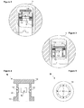
- Figure 1 - is the schematic view of the compressor of the present invention.
- Figure 2 - is the detailed schematic view of the oil suction duct when the valve is in the aspirating position in an embodiment of the present invention.
- Figure 3 - is the detailed schematic view of the oil suction duct when the valve is in the closed position in an embodiment of the present invention.
- Figure 4 - is the side schematic view of the valve in an embodiment of the present invention.
- Figure 5 - is the upper schematic view of the valve in an embodiment of the present invention.
- the compressor (1) comprises a motor (2) consisting of two main components, a stator (3) and a rotor (4), a crankshaft (5) that delivers the motion received from the motor (2), a cylinder block (7), a bearing (8) that maintains the crankshaft (5) to be born on the cylinder block (7) in the radial direction, an oil suction duct (6), which enables the lubricant oil to be sucked and which is secured to the end of the crankshaft (5), and a valve (9) allowing the lubricant oil to pass from the oil suction duct (6) to the bearing (8) during operation, but preventing the oil from turning back by closing in the course of stopping.
- the valve (9) is disposed in the oil suction duct (6) and comprises
- the compressor (1) furthermore comprises at least one set (10) located between the lower stopper (13) and the upper stopper (14) at the inner wall of the oil suction duct (6), whereon the lower stopper (13) bears from below during operation and the upper stopper (14) bears from above in the course stopping.
- the set (10) is ring-shaped.
- the valve (9) is seated at the center of the set (10) movable upwards and downwards, this movement is limited by the lower stopper (13) below and by the upper stopper (14) above.
- the holes (12) remain above the set (10) when the lower stopper (13) bears on the set (10) from below and thus, the lubricating oil located at the part of the body (11) that is at the lower side of the set (10) is delivered to the upper side of the set (10).
- the valve (9) moves upwards in the oil suction duct (6) by the effect of the suction and the pressure of the sucked oil and the lower stopper (13) bears on the set (10) from below.
- the body (11) of the valve (9) and hence, the holes (12) located on the body (11) remain at the side of the oil suction duct (6) that is above the set (10).
- the lubricating oil that is sucked into the oil suction duct (6) enters the body (11) through the open bottom of the valve (9) and proceeds to the side of the oil suction duct (6) that remains above the set (10) by exiting the holes (12).
- the lubricating oil provides the bearing (8) to be lubricated by reaching the bearing (8) from here.
- the valve (9) falls down by the end of the suction effect and by the effect of gravity when the compressor (1) stops.
- the upper stopper (14) bears on the set (10) from above and the body (11) of the valve (9) and hence the holes (12) located on the body (11) remain at the side of the oil suction duct (6) that is below the set (10). Therefore, the oil remaining at the side of the oil suction duct (6) that is above the set (10) will not be able to pass to the lower part of the set (10).
- an oil pool is formed on the set (10) in the oil suction duct (6) and the lubrication of the bearing (8) at the first start-up of the compressor (1) is provided by the oil accumulated in this pool.
- the valve (9) comprises more than one hole (12) located on the body (11) at the same height level equally distanced from each other, placed almost on a circle.
- the set (10) is located in the area where the oil suction duct (6) is secured to the crankshaft (5). Consequently, in the position where the valve (9) enables the lubricating oil to pass by elevating, the oil exiting the holes (12) directly reaches the crankshaft (5). Thus, the rapid lubrication during the first start-up is provided.
- the lower and upper stoppers (13, 14) are shaped like a ring flange each, disposed at the lower and the upper ends of the body (11).
- the stoppers (13, 14) are provided to seat on the set (10) in a balanced manner and almost leak-proofingly.
- the lower stoppers (13) are shaped like detent means each.
- the realization of the present invention is provided with low material costs.
Landscapes
- Engineering & Computer Science (AREA)
- Mechanical Engineering (AREA)
- General Engineering & Computer Science (AREA)
- Compressor (AREA)
- Rotary Pumps (AREA)
- Applications Or Details Of Rotary Compressors (AREA)
- Transition And Organic Metals Composition Catalysts For Addition Polymerization (AREA)
Abstract
Description
- The present invention relates to a compressor whereof the first start-up lubrication is improved.
- In household appliances, preferably in cooling devices, the circulation of the refrigerant used to provide the refrigeration is provided by a compressor. In the hermetic compressors utilized in cooling devices, the delivery of the lubricating oil to the bearings formed by the movable surfaces is provided by means of an oil suction duct.
- However, at the stop time of the compressor, the oil in the oil suction duct is drained into the lower casing by the effect of gravity. This results in an insufficient amount of lubricating oil to remain in the oil suction duct when the compressor operates again and causes dry friction in the bearings until the oil suction duct re-aspirates the lubricating oil in the lower casing for delivering to the bearings.
- In the state of the art Korean Patent Application No
KR20010038460 - In another state of the art Japanese Application No
JP2007255213 - Document
SU840464A - In these state of the art embodiments, the first lubrication cannot be provided as fast as required when the compressor is restarted after being stopped. This situation affects the efficiency of the compressor adversely and causes the movable parts to wear out in the course of time due to friction generated in the bearings during the first start-up.
- The aim of the present invention is the realization of a compressor whereof the lubrication at the first start-up is improved.
- The compressor realized in order to attain the aim of the present invention, explicated in the first claim and the respective claims thereof, comprises a valve disposed in the oil suction duct allowing the sucked lubricant oil to pass to the bearing during operation, but preventing the oil from turning back by closing in the course of stopping.
- The valve comprises an open bottom body in form of a cylinder, at least one hole located on the lateral surface of the body, at least one lower stopper extending along the wall of the oil suction duct at the lower end of the body and at least one upper stopper extending along the wall of the oil suction duct at the upper end of the body.
- The compressor furthermore comprises at least one ring-shaped set located between the lower stopper and the upper stopper at the inner wall of the oil suction duct. The valve is seated at the center of the set movable upwards and downwards. During the operation of the compressor, the lower stopper bears on the set from below by the oil being sucked. Thus, the oil sucked into the oil suction duct can pass to the upper side of the set and then to the bearing by exiting the holes after entering the valve.
- In the course of the stopping of the compressor, the upper stopper bears on the set from above because of the valve falling down by the effect of gravity. Since the holes remain below the set in this situation, the oil draining down the oil suction duct cannot pass to the lower side of the set since the entrance is totally closed by the set and the valve. Thus, the draining oil forms an oil pool by accumulating just on the set and the first lubrication of the bearing can be provided by this oil when the compressor starts operating again.
- In an embodiment of the present invention, the valve comprises more than one hole located at the same height level equally distanced from each other, placed almost on a circle.
- In an embodiment of the present invention, the set is located close by the point where the oil suction duct is mounted to the crankshaft. Consequently, in the position where the valve enables the lubricating oil to pass by elevating, the oil exiting the holes directly reaches the crankshaft. Thus, the rapid realization of the lubrication during the first start-up is provided.
- In the preferred embodiment of the present invention, the upper stopper is shaped like a ring flange.
- In different embodiments of the present invention, the lower stopper is shaped like a ring flange each or detent means.
- The model embodiments relating to a compressor realized in order to attain the aim of the present invention are illustrated in the attached figures, where:
-
Figure 1 - is the schematic view of the compressor of the present invention. -
Figure 2 - is the detailed schematic view of the oil suction duct when the valve is in the aspirating position in an embodiment of the present invention. -
Figure 3 - is the detailed schematic view of the oil suction duct when the valve is in the closed position in an embodiment of the present invention. -
Figure 4 - is the side schematic view of the valve in an embodiment of the present invention. -
Figure 5 - is the upper schematic view of the valve in an embodiment of the present invention. - The elements illustrated in the figures are numbered as follows:
- 1. Compressor
- 2. Motor
- 3. Stator
- 4. Rotor
- 5. Crankshaft
- 6. Oil Suction Duct
- 7. Cylinder Block
- 8. Bearing
- 9. Valve
- 10. Set
- 11. Body
- 12. Hole
- 13. Lower Stopper
- 14. Upper Stopper
- The compressor (1) comprises a motor (2) consisting of two main components, a stator (3) and a rotor (4), a crankshaft (5) that delivers the motion received from the motor (2), a cylinder block (7), a bearing (8) that maintains the crankshaft (5) to be born on the cylinder block (7) in the radial direction, an oil suction duct (6), which enables the lubricant oil to be sucked and which is secured to the end of the crankshaft (5), and a valve (9) allowing the lubricant oil to pass from the oil suction duct (6) to the bearing (8) during operation, but preventing the oil from turning back by closing in the course of stopping.
- The valve (9) is disposed in the oil suction duct (6) and comprises
- - an open bottom body (11) in form of a cylinder,
- - at least one hole (12) located on the lateral surface of the body (11),
- - at least one lower stopper (13) forming a protrusion towards the wall of the oil suction duct (6) at the lower end of the body (11) and
- - at least one upper stopper (14) forming a protrusion towards the wall of the oil suction duct (6) at the upper end of the body (11).
- The compressor (1) furthermore comprises at least one set (10) located between the lower stopper (13) and the upper stopper (14) at the inner wall of the oil suction duct (6), whereon the lower stopper (13) bears from below during operation and the upper stopper (14) bears from above in the course stopping.
- The set (10) is ring-shaped. The valve (9) is seated at the center of the set (10) movable upwards and downwards, this movement is limited by the lower stopper (13) below and by the upper stopper (14) above.
- The holes (12) remain above the set (10) when the lower stopper (13) bears on the set (10) from below and thus, the lubricating oil located at the part of the body (11) that is at the lower side of the set (10) is delivered to the upper side of the set (10).
- During the operation of the compressor (1), the valve (9) moves upwards in the oil suction duct (6) by the effect of the suction and the pressure of the sucked oil and the lower stopper (13) bears on the set (10) from below. In this position, the body (11) of the valve (9) and hence, the holes (12) located on the body (11) remain at the side of the oil suction duct (6) that is above the set (10). Thus, the lubricating oil that is sucked into the oil suction duct (6) enters the body (11) through the open bottom of the valve (9) and proceeds to the side of the oil suction duct (6) that remains above the set (10) by exiting the holes (12). The lubricating oil provides the bearing (8) to be lubricated by reaching the bearing (8) from here.
- The valve (9) falls down by the end of the suction effect and by the effect of gravity when the compressor (1) stops. In this position, the upper stopper (14) bears on the set (10) from above and the body (11) of the valve (9) and hence the holes (12) located on the body (11) remain at the side of the oil suction duct (6) that is below the set (10). Therefore, the oil remaining at the side of the oil suction duct (6) that is above the set (10) will not be able to pass to the lower part of the set (10). Thus, an oil pool is formed on the set (10) in the oil suction duct (6) and the lubrication of the bearing (8) at the first start-up of the compressor (1) is provided by the oil accumulated in this pool.
- In an embodiment of the present invention, the valve (9) comprises more than one hole (12) located on the body (11) at the same height level equally distanced from each other, placed almost on a circle.
- In an embodiment of the present invention, the set (10) is located in the area where the oil suction duct (6) is secured to the crankshaft (5). Consequently, in the position where the valve (9) enables the lubricating oil to pass by elevating, the oil exiting the holes (12) directly reaches the crankshaft (5). Thus, the rapid lubrication during the first start-up is provided.
- In the preferred embodiment of the present invention, the lower and upper stoppers (13, 14) are shaped like a ring flange each, disposed at the lower and the upper ends of the body (11). Thus, the stoppers (13, 14) are provided to seat on the set (10) in a balanced manner and almost leak-proofingly.
- In another embodiment of the present invention, the lower stoppers (13) are shaped like detent means each. Thus, the realization of the present invention is provided with low material costs.
- It is to be understood that the present invention is not limited to the embodiments disclosed above and an expert in the technique can easily introduce different embodiments. These may be within the scope of the protection, which is defined by the appended claims.
Claims (6)
- A compressor (1) that comprises a motor (2) consisting of two main components, a stator (3) and a rotor (4), a crankshaft (5) that delivers the motion received from the motor (2), a cylinder block (7), a bearing (8) that maintains the crankshaft (5) to be born on the cylinder block (7) in the radial direction, an oil suction duct (6) providing the lubricant oil to be sucked and secured to the end of the crankshaft (5) and a valve (9) disposed in the oil suction duct (6), allowing the lubricant oil to pass from the oil suction duct (6) to the bearing (8) during operation, but preventing the oil from turnina back by closing in the course of stopping and characterized in that the valve (9) has an open bottom body (11) in form of a cylinder, at least one hole (12) located on the lateral surface of the body (11), at least one lower stopper (13) forming a protrusion towards the wall of the oil suction duct (6) at the lower end of the body (11) and at least one upper stopper (14) forming a protrusion towards the wall of the oil suction duct (6) at the upper end of the body (11) and by a set (10) located between the lower stopper (13) and the upper stopper (14) at the inner wall of the oil suction duct (6), whereon the lower stopper (13) bears from below during operation and the upper stopper (14) bears from above in the course of stopping.
- A compressor (1) as in Claim 1, characterized in that the holes (12) remain above the set (10) when the lower stopper (13) bears on the set (10) from below.
- A compressor (1) as in Claim 1 or 2, characterized in that more than one hole (12) is located on the body (11) at the same height equally distanced from each other, placed almost on a circle.
- A compressor (1) as in any one of the above Claims, characterized in that the set (10) is located in the area where the oil suction duct (6) is secured to the crankshaft (5).
- A compressor (1) as in any one of the above Claims, characterized in that the lower and upper stoppers (13, 14) are shaped like a ring flange, disposed at the lower and the upper ends of the body (11).
- A compressor (1) as in any one of the Claims 1 to 4, characterized in that the lower stoppers (13) are shaped like detent means.
Priority Applications (1)
| Application Number | Priority Date | Filing Date | Title |
|---|---|---|---|
| SI200930152T SI2281118T1 (en) | 2008-05-02 | 2009-04-17 | A compressor |
Applications Claiming Priority (2)
| Application Number | Priority Date | Filing Date | Title |
|---|---|---|---|
| TR200803077 | 2008-05-02 | ||
| PCT/EP2009/054623 WO2009132975A1 (en) | 2008-05-02 | 2009-04-17 | A compressor |
Publications (2)
| Publication Number | Publication Date |
|---|---|
| EP2281118A1 EP2281118A1 (en) | 2011-02-09 |
| EP2281118B1 true EP2281118B1 (en) | 2011-11-02 |
Family
ID=40707823
Family Applications (1)
| Application Number | Title | Priority Date | Filing Date |
|---|---|---|---|
| EP09738019A Active EP2281118B1 (en) | 2008-05-02 | 2009-04-17 | A compressor |
Country Status (7)
| Country | Link |
|---|---|
| EP (1) | EP2281118B1 (en) |
| CN (1) | CN102016312B (en) |
| AT (1) | ATE531941T1 (en) |
| BR (1) | BRPI0911788A2 (en) |
| DK (1) | DK2281118T3 (en) |
| SI (1) | SI2281118T1 (en) |
| WO (1) | WO2009132975A1 (en) |
Families Citing this family (1)
| Publication number | Priority date | Publication date | Assignee | Title |
|---|---|---|---|---|
| KR102001335B1 (en) * | 2018-01-19 | 2019-07-17 | 엘지전자 주식회사 | A Lubricant Oil Provider and a Compressor Using the Same |
Family Cites Families (6)
| Publication number | Priority date | Publication date | Assignee | Title |
|---|---|---|---|---|
| US701607A (en) * | 1901-06-26 | 1902-06-03 | John W Park | Check-valve for pump-cylinders. |
| GB1247407A (en) * | 1969-05-02 | 1971-09-22 | Vanroy Ltd | Improvements in and relating to check valves |
| SU840464A1 (en) * | 1979-09-21 | 1981-06-23 | Предприятие П/Я Г-4371 | Apparatus for lubricating compressor |
| SE9703722L (en) * | 1997-10-13 | 1998-11-23 | Claes Lorentz Uno Wellton Pers | Lubrication system preferably for cooling compressors and comprising a pitot pump |
| CN2821214Y (en) * | 2005-07-13 | 2006-09-27 | 乐金电子(天津)电器有限公司 | Oil supply device for closed compressor |
| JP2007255213A (en) * | 2006-03-20 | 2007-10-04 | Mitsubishi Electric Corp | Refrigerant compressor |
-
2009
- 2009-04-17 EP EP09738019A patent/EP2281118B1/en active Active
- 2009-04-17 AT AT09738019T patent/ATE531941T1/en active
- 2009-04-17 SI SI200930152T patent/SI2281118T1/en unknown
- 2009-04-17 WO PCT/EP2009/054623 patent/WO2009132975A1/en not_active Ceased
- 2009-04-17 CN CN200980116585.0A patent/CN102016312B/en not_active Expired - Fee Related
- 2009-04-17 BR BRPI0911788A patent/BRPI0911788A2/en not_active IP Right Cessation
- 2009-04-17 DK DK09738019.0T patent/DK2281118T3/en active
Also Published As
| Publication number | Publication date |
|---|---|
| CN102016312B (en) | 2013-09-18 |
| EP2281118A1 (en) | 2011-02-09 |
| CN102016312A (en) | 2011-04-13 |
| ATE531941T1 (en) | 2011-11-15 |
| BRPI0911788A2 (en) | 2015-10-06 |
| WO2009132975A1 (en) | 2009-11-05 |
| DK2281118T3 (en) | 2012-02-06 |
| SI2281118T1 (en) | 2012-05-31 |
Similar Documents
| Publication | Publication Date | Title |
|---|---|---|
| CN1325796C (en) | Hermetic Electric Compressor | |
| WO2014103204A1 (en) | Scroll compressor | |
| JP5050393B2 (en) | Compressor | |
| US9541312B2 (en) | Passive oil level limiter | |
| EP2638290B1 (en) | A hermetic compressor comprising an oil sucking member | |
| EP2905469A1 (en) | Hermetic scroll compressor | |
| WO2009132975A1 (en) | A compressor | |
| EP3770430B1 (en) | A compressor with improved lubrication performance | |
| US10519958B2 (en) | Systems and methods to provide lubricant to a bearing | |
| WO2015049192A1 (en) | A compressor with improved lubrication effectiveness | |
| WO2016192976A1 (en) | Compressor with a movable oil suction apparatus | |
| WO2010133508A1 (en) | Hermetic compressor having increased lubrication effectiveness | |
| JP5503494B2 (en) | Hermetic compressor and refrigerator using the same | |
| CN103620219A (en) | A hermetic compressor comprising an oil sucking member | |
| JP2001295766A (en) | Closed compressor | |
| EP1954944B1 (en) | A compressor | |
| JP6766461B2 (en) | Compressor that can limit the lubrication of bearings | |
| JP6112853B2 (en) | Compressor | |
| CN105156330A (en) | Oil-return device for scroll compressor and scroll compressor | |
| CN105508252B (en) | Compressor with a compressor housing having a plurality of compressor blades | |
| WO2013097971A1 (en) | A hermetic compressor comprising an oil sucking member | |
| EP3215737B1 (en) | Improved rotor for use in an electric motor of a hermetic compressor | |
| WO2000077401A1 (en) | Motor-driven hermetic compressor | |
| WO2019037976A1 (en) | A compressor with improved lubrication performance | |
| JP2014084715A (en) | Hermetic compressor, and refrigerator |
Legal Events
| Date | Code | Title | Description |
|---|---|---|---|
| PUAI | Public reference made under article 153(3) epc to a published international application that has entered the european phase |
Free format text: ORIGINAL CODE: 0009012 |
|
| 17P | Request for examination filed |
Effective date: 20101026 |
|
| AK | Designated contracting states |
Kind code of ref document: A1 Designated state(s): AT BE BG CH CY CZ DE DK EE ES FI FR GB GR HR HU IE IS IT LI LT LU LV MC MK MT NL NO PL PT RO SE SI SK TR |
|
| AX | Request for extension of the european patent |
Extension state: AL BA RS |
|
| GRAP | Despatch of communication of intention to grant a patent |
Free format text: ORIGINAL CODE: EPIDOSNIGR1 |
|
| DAX | Request for extension of the european patent (deleted) | ||
| GRAS | Grant fee paid |
Free format text: ORIGINAL CODE: EPIDOSNIGR3 |
|
| GRAA | (expected) grant |
Free format text: ORIGINAL CODE: 0009210 |
|
| AK | Designated contracting states |
Kind code of ref document: B1 Designated state(s): AT BE BG CH CY CZ DE DK EE ES FI FR GB GR HR HU IE IS IT LI LT LU LV MC MK MT NL NO PL PT RO SE SI SK TR |
|
| REG | Reference to a national code |
Ref country code: GB Ref legal event code: FG4D |
|
| REG | Reference to a national code |
Ref country code: CH Ref legal event code: EP |
|
| REG | Reference to a national code |
Ref country code: IE Ref legal event code: FG4D |
|
| REG | Reference to a national code |
Ref country code: DE Ref legal event code: R096 Ref document number: 602009003485 Country of ref document: DE Effective date: 20120119 |
|
| REG | Reference to a national code |
Ref country code: DK Ref legal event code: T3 |
|
| REG | Reference to a national code |
Ref country code: NL Ref legal event code: VDEP Effective date: 20111102 |
|
| LTIE | Lt: invalidation of european patent or patent extension |
Effective date: 20111102 |
|
| PG25 | Lapsed in a contracting state [announced via postgrant information from national office to epo] |
Ref country code: LT Free format text: LAPSE BECAUSE OF FAILURE TO SUBMIT A TRANSLATION OF THE DESCRIPTION OR TO PAY THE FEE WITHIN THE PRESCRIBED TIME-LIMIT Effective date: 20111102 Ref country code: IS Free format text: LAPSE BECAUSE OF FAILURE TO SUBMIT A TRANSLATION OF THE DESCRIPTION OR TO PAY THE FEE WITHIN THE PRESCRIBED TIME-LIMIT Effective date: 20120302 Ref country code: NO Free format text: LAPSE BECAUSE OF FAILURE TO SUBMIT A TRANSLATION OF THE DESCRIPTION OR TO PAY THE FEE WITHIN THE PRESCRIBED TIME-LIMIT Effective date: 20120202 |
|
| PG25 | Lapsed in a contracting state [announced via postgrant information from national office to epo] |
Ref country code: NL Free format text: LAPSE BECAUSE OF FAILURE TO SUBMIT A TRANSLATION OF THE DESCRIPTION OR TO PAY THE FEE WITHIN THE PRESCRIBED TIME-LIMIT Effective date: 20111102 Ref country code: HR Free format text: LAPSE BECAUSE OF FAILURE TO SUBMIT A TRANSLATION OF THE DESCRIPTION OR TO PAY THE FEE WITHIN THE PRESCRIBED TIME-LIMIT Effective date: 20111102 Ref country code: BE Free format text: LAPSE BECAUSE OF FAILURE TO SUBMIT A TRANSLATION OF THE DESCRIPTION OR TO PAY THE FEE WITHIN THE PRESCRIBED TIME-LIMIT Effective date: 20111102 Ref country code: PL Free format text: LAPSE BECAUSE OF FAILURE TO SUBMIT A TRANSLATION OF THE DESCRIPTION OR TO PAY THE FEE WITHIN THE PRESCRIBED TIME-LIMIT Effective date: 20111102 Ref country code: SE Free format text: LAPSE BECAUSE OF FAILURE TO SUBMIT A TRANSLATION OF THE DESCRIPTION OR TO PAY THE FEE WITHIN THE PRESCRIBED TIME-LIMIT Effective date: 20111102 Ref country code: PT Free format text: LAPSE BECAUSE OF FAILURE TO SUBMIT A TRANSLATION OF THE DESCRIPTION OR TO PAY THE FEE WITHIN THE PRESCRIBED TIME-LIMIT Effective date: 20120302 Ref country code: GR Free format text: LAPSE BECAUSE OF FAILURE TO SUBMIT A TRANSLATION OF THE DESCRIPTION OR TO PAY THE FEE WITHIN THE PRESCRIBED TIME-LIMIT Effective date: 20120203 Ref country code: LV Free format text: LAPSE BECAUSE OF FAILURE TO SUBMIT A TRANSLATION OF THE DESCRIPTION OR TO PAY THE FEE WITHIN THE PRESCRIBED TIME-LIMIT Effective date: 20111102 |
|
| PG25 | Lapsed in a contracting state [announced via postgrant information from national office to epo] |
Ref country code: CY Free format text: LAPSE BECAUSE OF FAILURE TO SUBMIT A TRANSLATION OF THE DESCRIPTION OR TO PAY THE FEE WITHIN THE PRESCRIBED TIME-LIMIT Effective date: 20111102 |
|
| PG25 | Lapsed in a contracting state [announced via postgrant information from national office to epo] |
Ref country code: SK Free format text: LAPSE BECAUSE OF FAILURE TO SUBMIT A TRANSLATION OF THE DESCRIPTION OR TO PAY THE FEE WITHIN THE PRESCRIBED TIME-LIMIT Effective date: 20111102 Ref country code: CZ Free format text: LAPSE BECAUSE OF FAILURE TO SUBMIT A TRANSLATION OF THE DESCRIPTION OR TO PAY THE FEE WITHIN THE PRESCRIBED TIME-LIMIT Effective date: 20111102 Ref country code: EE Free format text: LAPSE BECAUSE OF FAILURE TO SUBMIT A TRANSLATION OF THE DESCRIPTION OR TO PAY THE FEE WITHIN THE PRESCRIBED TIME-LIMIT Effective date: 20111102 Ref country code: BG Free format text: LAPSE BECAUSE OF FAILURE TO SUBMIT A TRANSLATION OF THE DESCRIPTION OR TO PAY THE FEE WITHIN THE PRESCRIBED TIME-LIMIT Effective date: 20120202 |
|
| PG25 | Lapsed in a contracting state [announced via postgrant information from national office to epo] |
Ref country code: RO Free format text: LAPSE BECAUSE OF FAILURE TO SUBMIT A TRANSLATION OF THE DESCRIPTION OR TO PAY THE FEE WITHIN THE PRESCRIBED TIME-LIMIT Effective date: 20111102 |
|
| PLBE | No opposition filed within time limit |
Free format text: ORIGINAL CODE: 0009261 |
|
| STAA | Information on the status of an ep patent application or granted ep patent |
Free format text: STATUS: NO OPPOSITION FILED WITHIN TIME LIMIT |
|
| 26N | No opposition filed |
Effective date: 20120803 |
|
| REG | Reference to a national code |
Ref country code: DE Ref legal event code: R097 Ref document number: 602009003485 Country of ref document: DE Effective date: 20120803 |
|
| PG25 | Lapsed in a contracting state [announced via postgrant information from national office to epo] |
Ref country code: MC Free format text: LAPSE BECAUSE OF NON-PAYMENT OF DUE FEES Effective date: 20120430 |
|
| REG | Reference to a national code |
Ref country code: IE Ref legal event code: MM4A |
|
| REG | Reference to a national code |
Ref country code: FR Ref legal event code: ST Effective date: 20121228 |
|
| PG25 | Lapsed in a contracting state [announced via postgrant information from national office to epo] |
Ref country code: IE Free format text: LAPSE BECAUSE OF NON-PAYMENT OF DUE FEES Effective date: 20120417 |
|
| PG25 | Lapsed in a contracting state [announced via postgrant information from national office to epo] |
Ref country code: FR Free format text: LAPSE BECAUSE OF NON-PAYMENT OF DUE FEES Effective date: 20120430 Ref country code: MK Free format text: LAPSE BECAUSE OF FAILURE TO SUBMIT A TRANSLATION OF THE DESCRIPTION OR TO PAY THE FEE WITHIN THE PRESCRIBED TIME-LIMIT Effective date: 20111102 |
|
| PG25 | Lapsed in a contracting state [announced via postgrant information from national office to epo] |
Ref country code: ES Free format text: LAPSE BECAUSE OF FAILURE TO SUBMIT A TRANSLATION OF THE DESCRIPTION OR TO PAY THE FEE WITHIN THE PRESCRIBED TIME-LIMIT Effective date: 20120213 |
|
| PG25 | Lapsed in a contracting state [announced via postgrant information from national office to epo] |
Ref country code: FI Free format text: LAPSE BECAUSE OF FAILURE TO SUBMIT A TRANSLATION OF THE DESCRIPTION OR TO PAY THE FEE WITHIN THE PRESCRIBED TIME-LIMIT Effective date: 20111102 |
|
| PG25 | Lapsed in a contracting state [announced via postgrant information from national office to epo] |
Ref country code: MT Free format text: LAPSE BECAUSE OF FAILURE TO SUBMIT A TRANSLATION OF THE DESCRIPTION OR TO PAY THE FEE WITHIN THE PRESCRIBED TIME-LIMIT Effective date: 20111102 |
|
| REG | Reference to a national code |
Ref country code: CH Ref legal event code: PL |
|
| PG25 | Lapsed in a contracting state [announced via postgrant information from national office to epo] |
Ref country code: LI Free format text: LAPSE BECAUSE OF NON-PAYMENT OF DUE FEES Effective date: 20130430 Ref country code: CH Free format text: LAPSE BECAUSE OF NON-PAYMENT OF DUE FEES Effective date: 20130430 |
|
| PG25 | Lapsed in a contracting state [announced via postgrant information from national office to epo] |
Ref country code: LU Free format text: LAPSE BECAUSE OF NON-PAYMENT OF DUE FEES Effective date: 20120417 |
|
| PG25 | Lapsed in a contracting state [announced via postgrant information from national office to epo] |
Ref country code: HU Free format text: LAPSE BECAUSE OF FAILURE TO SUBMIT A TRANSLATION OF THE DESCRIPTION OR TO PAY THE FEE WITHIN THE PRESCRIBED TIME-LIMIT Effective date: 20090417 |
|
| PGFP | Annual fee paid to national office [announced via postgrant information from national office to epo] |
Ref country code: GB Payment date: 20170419 Year of fee payment: 9 Ref country code: DE Payment date: 20170419 Year of fee payment: 9 Ref country code: DK Payment date: 20170419 Year of fee payment: 9 |
|
| PGFP | Annual fee paid to national office [announced via postgrant information from national office to epo] |
Ref country code: AT Payment date: 20170420 Year of fee payment: 9 Ref country code: IT Payment date: 20170424 Year of fee payment: 9 Ref country code: SI Payment date: 20170328 Year of fee payment: 9 |
|
| REG | Reference to a national code |
Ref country code: DE Ref legal event code: R119 Ref document number: 602009003485 Country of ref document: DE |
|
| REG | Reference to a national code |
Ref country code: DK Ref legal event code: EBP Effective date: 20180430 |
|
| REG | Reference to a national code |
Ref country code: AT Ref legal event code: MM01 Ref document number: 531941 Country of ref document: AT Kind code of ref document: T Effective date: 20180417 |
|
| GBPC | Gb: european patent ceased through non-payment of renewal fee |
Effective date: 20180417 |
|
| PG25 | Lapsed in a contracting state [announced via postgrant information from national office to epo] |
Ref country code: DE Free format text: LAPSE BECAUSE OF NON-PAYMENT OF DUE FEES Effective date: 20181101 Ref country code: AT Free format text: LAPSE BECAUSE OF NON-PAYMENT OF DUE FEES Effective date: 20180417 |
|
| REG | Reference to a national code |
Ref country code: SI Ref legal event code: KO00 Effective date: 20181204 |
|
| PG25 | Lapsed in a contracting state [announced via postgrant information from national office to epo] |
Ref country code: SI Free format text: LAPSE BECAUSE OF NON-PAYMENT OF DUE FEES Effective date: 20180418 Ref country code: GB Free format text: LAPSE BECAUSE OF NON-PAYMENT OF DUE FEES Effective date: 20180417 |
|
| PG25 | Lapsed in a contracting state [announced via postgrant information from national office to epo] |
Ref country code: IT Free format text: LAPSE BECAUSE OF NON-PAYMENT OF DUE FEES Effective date: 20180417 |
|
| PG25 | Lapsed in a contracting state [announced via postgrant information from national office to epo] |
Ref country code: DK Free format text: LAPSE BECAUSE OF NON-PAYMENT OF DUE FEES Effective date: 20180430 |
|
| PGFP | Annual fee paid to national office [announced via postgrant information from national office to epo] |
Ref country code: TR Payment date: 20260312 Year of fee payment: 18 |