EP2280905B1 - Multilevel microfluidic systems and methods - Google Patents
Multilevel microfluidic systems and methods Download PDFInfo
- Publication number
- EP2280905B1 EP2280905B1 EP09730165.9A EP09730165A EP2280905B1 EP 2280905 B1 EP2280905 B1 EP 2280905B1 EP 09730165 A EP09730165 A EP 09730165A EP 2280905 B1 EP2280905 B1 EP 2280905B1
- Authority
- EP
- European Patent Office
- Prior art keywords
- layer
- channel
- chamber
- flow
- reaction
- Prior art date
- Legal status (The legal status is an assumption and is not a legal conclusion. Google has not performed a legal analysis and makes no representation as to the accuracy of the status listed.)
- Active
Links
- 238000000034 method Methods 0.000 title description 113
- 238000006243 chemical reaction Methods 0.000 claims description 163
- 239000012530 fluid Substances 0.000 claims description 77
- 238000002955 isolation Methods 0.000 claims description 74
- 239000000758 substrate Substances 0.000 claims description 55
- 238000004891 communication Methods 0.000 claims description 53
- 239000012528 membrane Substances 0.000 claims description 19
- 239000013536 elastomeric material Substances 0.000 claims description 11
- 230000008859 change Effects 0.000 claims description 9
- 239000010410 layer Substances 0.000 description 243
- 239000000463 material Substances 0.000 description 127
- 239000000523 sample Substances 0.000 description 105
- 150000007523 nucleic acids Chemical class 0.000 description 47
- 108020004707 nucleic acids Proteins 0.000 description 45
- 102000039446 nucleic acids Human genes 0.000 description 45
- 239000003153 chemical reaction reagent Substances 0.000 description 44
- 229920002120 photoresistant polymer Polymers 0.000 description 38
- 210000004027 cell Anatomy 0.000 description 28
- -1 poly(styrene-butadiene-styrene) Polymers 0.000 description 28
- 230000000875 corresponding effect Effects 0.000 description 27
- 229920000642 polymer Polymers 0.000 description 22
- 230000008569 process Effects 0.000 description 22
- 239000012491 analyte Substances 0.000 description 21
- 238000003556 assay Methods 0.000 description 21
- 239000004205 dimethyl polysiloxane Substances 0.000 description 18
- 229920001971 elastomer Polymers 0.000 description 18
- 239000000806 elastomer Substances 0.000 description 18
- 229920000435 poly(dimethylsiloxane) Polymers 0.000 description 18
- 238000004519 manufacturing process Methods 0.000 description 16
- 230000003321 amplification Effects 0.000 description 14
- 238000011068 loading method Methods 0.000 description 14
- 238000003199 nucleic acid amplification method Methods 0.000 description 14
- 239000000872 buffer Substances 0.000 description 13
- 238000002156 mixing Methods 0.000 description 13
- 239000000203 mixture Substances 0.000 description 13
- PEDCQBHIVMGVHV-UHFFFAOYSA-N Glycerine Chemical compound OCC(O)CO PEDCQBHIVMGVHV-UHFFFAOYSA-N 0.000 description 12
- 239000000975 dye Substances 0.000 description 12
- KWIUHFFTVRNATP-UHFFFAOYSA-N glycine betaine Chemical compound C[N+](C)(C)CC([O-])=O KWIUHFFTVRNATP-UHFFFAOYSA-N 0.000 description 12
- 108090000623 proteins and genes Proteins 0.000 description 11
- 201000010099 disease Diseases 0.000 description 10
- 208000037265 diseases, disorders, signs and symptoms Diseases 0.000 description 10
- 238000005530 etching Methods 0.000 description 10
- 239000011159 matrix material Substances 0.000 description 10
- 108020004414 DNA Proteins 0.000 description 9
- 239000007788 liquid Substances 0.000 description 9
- 238000007789 sealing Methods 0.000 description 9
- 230000000295 complement effect Effects 0.000 description 8
- 238000001514 detection method Methods 0.000 description 8
- 238000006460 hydrolysis reaction Methods 0.000 description 8
- 230000004048 modification Effects 0.000 description 8
- 238000012986 modification Methods 0.000 description 8
- 238000001080 multi-layer soft lithography Methods 0.000 description 8
- 108020004711 Nucleic Acid Probes Proteins 0.000 description 7
- 230000015572 biosynthetic process Effects 0.000 description 7
- 239000007789 gas Substances 0.000 description 7
- 239000002853 nucleic acid probe Substances 0.000 description 7
- 229920001223 polyethylene glycol Polymers 0.000 description 7
- 102000004169 proteins and genes Human genes 0.000 description 7
- 230000008901 benefit Effects 0.000 description 6
- 229960003237 betaine Drugs 0.000 description 6
- 230000007062 hydrolysis Effects 0.000 description 6
- 239000000178 monomer Substances 0.000 description 6
- 239000000243 solution Substances 0.000 description 6
- XUIMIQQOPSSXEZ-UHFFFAOYSA-N Silicon Chemical compound [Si] XUIMIQQOPSSXEZ-UHFFFAOYSA-N 0.000 description 5
- 239000003795 chemical substances by application Substances 0.000 description 5
- 238000011161 development Methods 0.000 description 5
- 238000002866 fluorescence resonance energy transfer Methods 0.000 description 5
- 238000007689 inspection Methods 0.000 description 5
- 230000007246 mechanism Effects 0.000 description 5
- 239000000047 product Substances 0.000 description 5
- 230000005855 radiation Effects 0.000 description 5
- 229910052710 silicon Inorganic materials 0.000 description 5
- 239000010703 silicon Substances 0.000 description 5
- 239000000126 substance Substances 0.000 description 5
- XLYOFNOQVPJJNP-UHFFFAOYSA-N water Substances O XLYOFNOQVPJJNP-UHFFFAOYSA-N 0.000 description 5
- KAKZBPTYRLMSJV-UHFFFAOYSA-N Butadiene Chemical compound C=CC=C KAKZBPTYRLMSJV-UHFFFAOYSA-N 0.000 description 4
- RRHGJUQNOFWUDK-UHFFFAOYSA-N Isoprene Chemical compound CC(=C)C=C RRHGJUQNOFWUDK-UHFFFAOYSA-N 0.000 description 4
- 108091034117 Oligonucleotide Proteins 0.000 description 4
- 229920002367 Polyisobutene Polymers 0.000 description 4
- 229920001213 Polysorbate 20 Polymers 0.000 description 4
- 238000002679 ablation Methods 0.000 description 4
- 239000000853 adhesive Substances 0.000 description 4
- 230000001070 adhesive effect Effects 0.000 description 4
- 238000004458 analytical method Methods 0.000 description 4
- 230000027455 binding Effects 0.000 description 4
- 238000002425 crystallisation Methods 0.000 description 4
- 230000008025 crystallization Effects 0.000 description 4
- MTHSVFCYNBDYFN-UHFFFAOYSA-N diethylene glycol Chemical compound OCCOCCO MTHSVFCYNBDYFN-UHFFFAOYSA-N 0.000 description 4
- 230000000694 effects Effects 0.000 description 4
- 238000005538 encapsulation Methods 0.000 description 4
- 230000006870 function Effects 0.000 description 4
- 238000010438 heat treatment Methods 0.000 description 4
- 238000003384 imaging method Methods 0.000 description 4
- 238000000608 laser ablation Methods 0.000 description 4
- 239000002773 nucleotide Substances 0.000 description 4
- 125000003729 nucleotide group Chemical group 0.000 description 4
- 229920000515 polycarbonate Polymers 0.000 description 4
- 239000004417 polycarbonate Substances 0.000 description 4
- 239000000256 polyoxyethylene sorbitan monolaurate Substances 0.000 description 4
- 235000010486 polyoxyethylene sorbitan monolaurate Nutrition 0.000 description 4
- 229920002635 polyurethane Polymers 0.000 description 4
- 239000004814 polyurethane Substances 0.000 description 4
- 238000011002 quantification Methods 0.000 description 4
- 238000003753 real-time PCR Methods 0.000 description 4
- 238000004528 spin coating Methods 0.000 description 4
- 238000003786 synthesis reaction Methods 0.000 description 4
- FPGGTKZVZWFYPV-UHFFFAOYSA-M tetrabutylammonium fluoride Chemical compound [F-].CCCC[N+](CCCC)(CCCC)CCCC FPGGTKZVZWFYPV-UHFFFAOYSA-M 0.000 description 4
- 108090000790 Enzymes Proteins 0.000 description 3
- 102000004190 Enzymes Human genes 0.000 description 3
- 239000005062 Polybutadiene Substances 0.000 description 3
- 239000004743 Polypropylene Substances 0.000 description 3
- 239000004793 Polystyrene Substances 0.000 description 3
- 108010006785 Taq Polymerase Proteins 0.000 description 3
- 229920006362 Teflon® Polymers 0.000 description 3
- 101150003160 X gene Proteins 0.000 description 3
- 101150044453 Y gene Proteins 0.000 description 3
- 238000000137 annealing Methods 0.000 description 3
- 239000011248 coating agent Substances 0.000 description 3
- 238000000576 coating method Methods 0.000 description 3
- 238000001723 curing Methods 0.000 description 3
- 230000005670 electromagnetic radiation Effects 0.000 description 3
- 239000007850 fluorescent dye Substances 0.000 description 3
- 239000011521 glass Substances 0.000 description 3
- 239000010931 gold Substances 0.000 description 3
- 229910052737 gold Inorganic materials 0.000 description 3
- 238000009396 hybridization Methods 0.000 description 3
- 238000000465 moulding Methods 0.000 description 3
- 229920003023 plastic Polymers 0.000 description 3
- 239000004033 plastic Substances 0.000 description 3
- 229920001084 poly(chloroprene) Polymers 0.000 description 3
- 229920003229 poly(methyl methacrylate) Polymers 0.000 description 3
- 229920002857 polybutadiene Polymers 0.000 description 3
- 229920001195 polyisoprene Polymers 0.000 description 3
- 239000004926 polymethyl methacrylate Substances 0.000 description 3
- 229920001155 polypropylene Polymers 0.000 description 3
- 229920002223 polystyrene Polymers 0.000 description 3
- 229920001343 polytetrafluoroethylene Polymers 0.000 description 3
- 239000004810 polytetrafluoroethylene Substances 0.000 description 3
- 230000000171 quenching effect Effects 0.000 description 3
- 229920005573 silicon-containing polymer Polymers 0.000 description 3
- 239000002904 solvent Substances 0.000 description 3
- 210000001519 tissue Anatomy 0.000 description 3
- 238000004073 vulcanization Methods 0.000 description 3
- 229910001868 water Inorganic materials 0.000 description 3
- YBJHBAHKTGYVGT-ZKWXMUAHSA-N (+)-Biotin Chemical compound N1C(=O)N[C@@H]2[C@H](CCCCC(=O)O)SC[C@@H]21 YBJHBAHKTGYVGT-ZKWXMUAHSA-N 0.000 description 2
- KDCGOANMDULRCW-UHFFFAOYSA-N 7H-purine Chemical compound N1=CNC2=NC=NC2=C1 KDCGOANMDULRCW-UHFFFAOYSA-N 0.000 description 2
- TWRXJAOTZQYOKJ-UHFFFAOYSA-L Magnesium chloride Chemical compound [Mg+2].[Cl-].[Cl-] TWRXJAOTZQYOKJ-UHFFFAOYSA-L 0.000 description 2
- 238000012408 PCR amplification Methods 0.000 description 2
- 239000004809 Teflon Substances 0.000 description 2
- JLCPHMBAVCMARE-UHFFFAOYSA-N [3-[[3-[[3-[[3-[[3-[[3-[[3-[[3-[[3-[[3-[[3-[[5-(2-amino-6-oxo-1H-purin-9-yl)-3-[[3-[[3-[[3-[[3-[[3-[[5-(2-amino-6-oxo-1H-purin-9-yl)-3-[[5-(2-amino-6-oxo-1H-purin-9-yl)-3-hydroxyoxolan-2-yl]methoxy-hydroxyphosphoryl]oxyoxolan-2-yl]methoxy-hydroxyphosphoryl]oxy-5-(5-methyl-2,4-dioxopyrimidin-1-yl)oxolan-2-yl]methoxy-hydroxyphosphoryl]oxy-5-(6-aminopurin-9-yl)oxolan-2-yl]methoxy-hydroxyphosphoryl]oxy-5-(6-aminopurin-9-yl)oxolan-2-yl]methoxy-hydroxyphosphoryl]oxy-5-(6-aminopurin-9-yl)oxolan-2-yl]methoxy-hydroxyphosphoryl]oxy-5-(6-aminopurin-9-yl)oxolan-2-yl]methoxy-hydroxyphosphoryl]oxyoxolan-2-yl]methoxy-hydroxyphosphoryl]oxy-5-(5-methyl-2,4-dioxopyrimidin-1-yl)oxolan-2-yl]methoxy-hydroxyphosphoryl]oxy-5-(4-amino-2-oxopyrimidin-1-yl)oxolan-2-yl]methoxy-hydroxyphosphoryl]oxy-5-(5-methyl-2,4-dioxopyrimidin-1-yl)oxolan-2-yl]methoxy-hydroxyphosphoryl]oxy-5-(5-methyl-2,4-dioxopyrimidin-1-yl)oxolan-2-yl]methoxy-hydroxyphosphoryl]oxy-5-(6-aminopurin-9-yl)oxolan-2-yl]methoxy-hydroxyphosphoryl]oxy-5-(6-aminopurin-9-yl)oxolan-2-yl]methoxy-hydroxyphosphoryl]oxy-5-(4-amino-2-oxopyrimidin-1-yl)oxolan-2-yl]methoxy-hydroxyphosphoryl]oxy-5-(4-amino-2-oxopyrimidin-1-yl)oxolan-2-yl]methoxy-hydroxyphosphoryl]oxy-5-(4-amino-2-oxopyrimidin-1-yl)oxolan-2-yl]methoxy-hydroxyphosphoryl]oxy-5-(6-aminopurin-9-yl)oxolan-2-yl]methoxy-hydroxyphosphoryl]oxy-5-(4-amino-2-oxopyrimidin-1-yl)oxolan-2-yl]methyl [5-(6-aminopurin-9-yl)-2-(hydroxymethyl)oxolan-3-yl] hydrogen phosphate Polymers Cc1cn(C2CC(OP(O)(=O)OCC3OC(CC3OP(O)(=O)OCC3OC(CC3O)n3cnc4c3nc(N)[nH]c4=O)n3cnc4c3nc(N)[nH]c4=O)C(COP(O)(=O)OC3CC(OC3COP(O)(=O)OC3CC(OC3COP(O)(=O)OC3CC(OC3COP(O)(=O)OC3CC(OC3COP(O)(=O)OC3CC(OC3COP(O)(=O)OC3CC(OC3COP(O)(=O)OC3CC(OC3COP(O)(=O)OC3CC(OC3COP(O)(=O)OC3CC(OC3COP(O)(=O)OC3CC(OC3COP(O)(=O)OC3CC(OC3COP(O)(=O)OC3CC(OC3COP(O)(=O)OC3CC(OC3COP(O)(=O)OC3CC(OC3COP(O)(=O)OC3CC(OC3COP(O)(=O)OC3CC(OC3COP(O)(=O)OC3CC(OC3CO)n3cnc4c(N)ncnc34)n3ccc(N)nc3=O)n3cnc4c(N)ncnc34)n3ccc(N)nc3=O)n3ccc(N)nc3=O)n3ccc(N)nc3=O)n3cnc4c(N)ncnc34)n3cnc4c(N)ncnc34)n3cc(C)c(=O)[nH]c3=O)n3cc(C)c(=O)[nH]c3=O)n3ccc(N)nc3=O)n3cc(C)c(=O)[nH]c3=O)n3cnc4c3nc(N)[nH]c4=O)n3cnc4c(N)ncnc34)n3cnc4c(N)ncnc34)n3cnc4c(N)ncnc34)n3cnc4c(N)ncnc34)O2)c(=O)[nH]c1=O JLCPHMBAVCMARE-UHFFFAOYSA-N 0.000 description 2
- 239000002390 adhesive tape Substances 0.000 description 2
- 150000001412 amines Chemical class 0.000 description 2
- 238000013459 approach Methods 0.000 description 2
- 238000003491 array Methods 0.000 description 2
- 239000002299 complementary DNA Substances 0.000 description 2
- 238000010276 construction Methods 0.000 description 2
- 238000001816 cooling Methods 0.000 description 2
- 238000004132 cross linking Methods 0.000 description 2
- OPTASPLRGRRNAP-UHFFFAOYSA-N cytosine Chemical compound NC=1C=CNC(=O)N=1 OPTASPLRGRRNAP-UHFFFAOYSA-N 0.000 description 2
- 239000008367 deionised water Substances 0.000 description 2
- 229910021641 deionized water Inorganic materials 0.000 description 2
- 238000013461 design Methods 0.000 description 2
- 238000005516 engineering process Methods 0.000 description 2
- MURGITYSBWUQTI-UHFFFAOYSA-N fluorescin Chemical compound OC(=O)C1=CC=CC=C1C1C2=CC=C(O)C=C2OC2=CC(O)=CC=C21 MURGITYSBWUQTI-UHFFFAOYSA-N 0.000 description 2
- 238000003205 genotyping method Methods 0.000 description 2
- 239000012948 isocyanate Substances 0.000 description 2
- 239000003446 ligand Substances 0.000 description 2
- 238000001459 lithography Methods 0.000 description 2
- 230000033001 locomotion Effects 0.000 description 2
- 229910052751 metal Inorganic materials 0.000 description 2
- 239000002184 metal Substances 0.000 description 2
- 238000005459 micromachining Methods 0.000 description 2
- 238000012544 monitoring process Methods 0.000 description 2
- 238000007857 nested PCR Methods 0.000 description 2
- 238000001020 plasma etching Methods 0.000 description 2
- 229910021420 polycrystalline silicon Inorganic materials 0.000 description 2
- 238000003752 polymerase chain reaction Methods 0.000 description 2
- 238000007858 polymerase cycling assembly Methods 0.000 description 2
- 238000006116 polymerization reaction Methods 0.000 description 2
- 229920005591 polysilicon Polymers 0.000 description 2
- 229920001296 polysiloxane Polymers 0.000 description 2
- 238000002360 preparation method Methods 0.000 description 2
- 238000012545 processing Methods 0.000 description 2
- 235000007682 pyridoxal 5'-phosphate Nutrition 0.000 description 2
- 230000009467 reduction Effects 0.000 description 2
- 230000003362 replicative effect Effects 0.000 description 2
- 238000012216 screening Methods 0.000 description 2
- 238000002174 soft lithography Methods 0.000 description 2
- 238000012360 testing method Methods 0.000 description 2
- 238000005382 thermal cycling Methods 0.000 description 2
- 238000012546 transfer Methods 0.000 description 2
- 239000012780 transparent material Substances 0.000 description 2
- 238000011144 upstream manufacturing Methods 0.000 description 2
- RGNOTKMIMZMNRX-XVFCMESISA-N 2-amino-1-[(2r,3r,4s,5r)-3,4-dihydroxy-5-(hydroxymethyl)oxolan-2-yl]pyrimidin-4-one Chemical compound NC1=NC(=O)C=CN1[C@H]1[C@H](O)[C@H](O)[C@@H](CO)O1 RGNOTKMIMZMNRX-XVFCMESISA-N 0.000 description 1
- LQLQRFGHAALLLE-UHFFFAOYSA-N 5-bromouracil Chemical compound BrC1=CNC(=O)NC1=O LQLQRFGHAALLLE-UHFFFAOYSA-N 0.000 description 1
- QTBSBXVTEAMEQO-UHFFFAOYSA-M Acetate Chemical compound CC([O-])=O QTBSBXVTEAMEQO-UHFFFAOYSA-M 0.000 description 1
- 108091093088 Amplicon Proteins 0.000 description 1
- 108091003079 Bovine Serum Albumin Proteins 0.000 description 1
- 239000005046 Chlorosilane Substances 0.000 description 1
- 230000004544 DNA amplification Effects 0.000 description 1
- 230000004543 DNA replication Effects 0.000 description 1
- 108010014303 DNA-directed DNA polymerase Proteins 0.000 description 1
- 102000016928 DNA-directed DNA polymerase Human genes 0.000 description 1
- BVTJGGGYKAMDBN-UHFFFAOYSA-N Dioxetane Chemical class C1COO1 BVTJGGGYKAMDBN-UHFFFAOYSA-N 0.000 description 1
- 229920002449 FKM Polymers 0.000 description 1
- 229920004459 Kel-F® PCTFE Polymers 0.000 description 1
- 241001465754 Metazoa Species 0.000 description 1
- 108060004795 Methyltransferase Proteins 0.000 description 1
- 206010028980 Neoplasm Diseases 0.000 description 1
- 229920000459 Nitrile rubber Polymers 0.000 description 1
- 101710163270 Nuclease Proteins 0.000 description 1
- 108091005461 Nucleic proteins Proteins 0.000 description 1
- 108091093037 Peptide nucleic acid Proteins 0.000 description 1
- 239000004698 Polyethylene Substances 0.000 description 1
- 239000002202 Polyethylene glycol Substances 0.000 description 1
- CZPWVGJYEJSRLH-UHFFFAOYSA-N Pyrimidine Chemical compound C1=CN=CN=C1 CZPWVGJYEJSRLH-UHFFFAOYSA-N 0.000 description 1
- 238000011529 RT qPCR Methods 0.000 description 1
- NINIDFKCEFEMDL-UHFFFAOYSA-N Sulfur Chemical compound [S] NINIDFKCEFEMDL-UHFFFAOYSA-N 0.000 description 1
- 238000002441 X-ray diffraction Methods 0.000 description 1
- 230000009102 absorption Effects 0.000 description 1
- 238000010521 absorption reaction Methods 0.000 description 1
- 238000009825 accumulation Methods 0.000 description 1
- 230000006978 adaptation Effects 0.000 description 1
- 239000000654 additive Substances 0.000 description 1
- 238000011166 aliquoting Methods 0.000 description 1
- 238000007844 allele-specific PCR Methods 0.000 description 1
- 125000003275 alpha amino acid group Chemical group 0.000 description 1
- 229910052782 aluminium Inorganic materials 0.000 description 1
- XAGFODPZIPBFFR-UHFFFAOYSA-N aluminium Chemical compound [Al] XAGFODPZIPBFFR-UHFFFAOYSA-N 0.000 description 1
- 239000012062 aqueous buffer Substances 0.000 description 1
- 238000007845 assembly PCR Methods 0.000 description 1
- 238000012742 biochemical analysis Methods 0.000 description 1
- 229960002685 biotin Drugs 0.000 description 1
- 235000020958 biotin Nutrition 0.000 description 1
- 239000011616 biotin Substances 0.000 description 1
- 230000000903 blocking effect Effects 0.000 description 1
- 210000000601 blood cell Anatomy 0.000 description 1
- 229940098773 bovine serum albumin Drugs 0.000 description 1
- 238000001818 capillary gel electrophoresis Methods 0.000 description 1
- 229920003237 carborane-containing polymer Polymers 0.000 description 1
- 239000000969 carrier Substances 0.000 description 1
- 239000000919 ceramic Substances 0.000 description 1
- 125000003636 chemical group Chemical group 0.000 description 1
- 238000007385 chemical modification Methods 0.000 description 1
- KOPOQZFJUQMUML-UHFFFAOYSA-N chlorosilane Chemical class Cl[SiH3] KOPOQZFJUQMUML-UHFFFAOYSA-N 0.000 description 1
- UUAGAQFQZIEFAH-UHFFFAOYSA-N chlorotrifluoroethylene Chemical compound FC(F)=C(F)Cl UUAGAQFQZIEFAH-UHFFFAOYSA-N 0.000 description 1
- 238000004587 chromatography analysis Methods 0.000 description 1
- 230000000052 comparative effect Effects 0.000 description 1
- 150000001875 compounds Chemical class 0.000 description 1
- 238000007906 compression Methods 0.000 description 1
- 230000006835 compression Effects 0.000 description 1
- 239000000470 constituent Substances 0.000 description 1
- 239000000356 contaminant Substances 0.000 description 1
- 229920001577 copolymer Polymers 0.000 description 1
- 230000002596 correlated effect Effects 0.000 description 1
- 239000007822 coupling agent Substances 0.000 description 1
- 238000005336 cracking Methods 0.000 description 1
- 239000003431 cross linking reagent Substances 0.000 description 1
- 239000013078 crystal Substances 0.000 description 1
- 229940104302 cytosine Drugs 0.000 description 1
- 230000006735 deficit Effects 0.000 description 1
- 230000001419 dependent effect Effects 0.000 description 1
- 238000000151 deposition Methods 0.000 description 1
- 230000008021 deposition Effects 0.000 description 1
- 238000005137 deposition process Methods 0.000 description 1
- 150000004985 diamines Chemical class 0.000 description 1
- 150000001993 dienes Chemical class 0.000 description 1
- 238000003618 dip coating Methods 0.000 description 1
- 238000009826 distribution Methods 0.000 description 1
- 238000005553 drilling Methods 0.000 description 1
- 238000001035 drying Methods 0.000 description 1
- 230000009977 dual effect Effects 0.000 description 1
- 238000001962 electrophoresis Methods 0.000 description 1
- 230000009881 electrostatic interaction Effects 0.000 description 1
- 230000007613 environmental effect Effects 0.000 description 1
- 230000002255 enzymatic effect Effects 0.000 description 1
- 238000013401 experimental design Methods 0.000 description 1
- 238000011049 filling Methods 0.000 description 1
- 229920002313 fluoropolymer Polymers 0.000 description 1
- 239000004811 fluoropolymer Substances 0.000 description 1
- 230000004907 flux Effects 0.000 description 1
- 238000009472 formulation Methods 0.000 description 1
- 238000004817 gas chromatography Methods 0.000 description 1
- 230000014509 gene expression Effects 0.000 description 1
- 230000009477 glass transition Effects 0.000 description 1
- PCHJSUWPFVWCPO-UHFFFAOYSA-N gold Chemical compound [Au] PCHJSUWPFVWCPO-UHFFFAOYSA-N 0.000 description 1
- 229920001903 high density polyethylene Polymers 0.000 description 1
- 239000004700 high-density polyethylene Substances 0.000 description 1
- 238000007849 hot-start PCR Methods 0.000 description 1
- 239000001257 hydrogen Substances 0.000 description 1
- 229910052739 hydrogen Inorganic materials 0.000 description 1
- 238000003018 immunoassay Methods 0.000 description 1
- 238000012606 in vitro cell culture Methods 0.000 description 1
- 238000011065 in-situ storage Methods 0.000 description 1
- 239000004615 ingredient Substances 0.000 description 1
- 238000002347 injection Methods 0.000 description 1
- 239000007924 injection Substances 0.000 description 1
- 238000001746 injection moulding Methods 0.000 description 1
- 229910010272 inorganic material Inorganic materials 0.000 description 1
- 239000011147 inorganic material Substances 0.000 description 1
- 230000010354 integration Effects 0.000 description 1
- 230000003993 interaction Effects 0.000 description 1
- 239000011229 interlayer Substances 0.000 description 1
- 230000000968 intestinal effect Effects 0.000 description 1
- 238000007852 inverse PCR Methods 0.000 description 1
- 238000002032 lab-on-a-chip Methods 0.000 description 1
- 238000002372 labelling Methods 0.000 description 1
- 238000007854 ligation-mediated PCR Methods 0.000 description 1
- 238000010551 living anionic polymerization reaction Methods 0.000 description 1
- 210000004880 lymph fluid Anatomy 0.000 description 1
- 238000007403 mPCR Methods 0.000 description 1
- 229910001629 magnesium chloride Inorganic materials 0.000 description 1
- 230000005389 magnetism Effects 0.000 description 1
- 238000005259 measurement Methods 0.000 description 1
- 230000001404 mediated effect Effects 0.000 description 1
- 239000000155 melt Substances 0.000 description 1
- 150000002739 metals Chemical class 0.000 description 1
- 230000011987 methylation Effects 0.000 description 1
- 238000007069 methylation reaction Methods 0.000 description 1
- 238000007855 methylation-specific PCR Methods 0.000 description 1
- 239000002991 molded plastic Substances 0.000 description 1
- 238000007838 multiplex ligation-dependent probe amplification Methods 0.000 description 1
- GKTNLYAAZKKMTQ-UHFFFAOYSA-N n-[bis(dimethylamino)phosphinimyl]-n-methylmethanamine Chemical compound CN(C)P(=N)(N(C)C)N(C)C GKTNLYAAZKKMTQ-UHFFFAOYSA-N 0.000 description 1
- 239000002105 nanoparticle Substances 0.000 description 1
- 238000013188 needle biopsy Methods 0.000 description 1
- 210000000056 organ Anatomy 0.000 description 1
- 239000003960 organic solvent Substances 0.000 description 1
- 239000012188 paraffin wax Substances 0.000 description 1
- 239000002245 particle Substances 0.000 description 1
- 230000037361 pathway Effects 0.000 description 1
- 230000035699 permeability Effects 0.000 description 1
- 239000012466 permeate Substances 0.000 description 1
- 239000012071 phase Substances 0.000 description 1
- PARWUHTVGZSQPD-UHFFFAOYSA-N phenylsilane Chemical class [SiH3]C1=CC=CC=C1 PARWUHTVGZSQPD-UHFFFAOYSA-N 0.000 description 1
- 238000000016 photochemical curing Methods 0.000 description 1
- 229920002492 poly(sulfone) Polymers 0.000 description 1
- 229920001748 polybutylene Polymers 0.000 description 1
- 229920000728 polyester Polymers 0.000 description 1
- 229920000573 polyethylene Polymers 0.000 description 1
- 108091033319 polynucleotide Proteins 0.000 description 1
- 102000040430 polynucleotide Human genes 0.000 description 1
- 239000002157 polynucleotide Substances 0.000 description 1
- 229920001184 polypeptide Polymers 0.000 description 1
- 239000004800 polyvinyl chloride Substances 0.000 description 1
- 229920002981 polyvinylidene fluoride Polymers 0.000 description 1
- 239000002243 precursor Substances 0.000 description 1
- 238000003825 pressing Methods 0.000 description 1
- 239000013615 primer Substances 0.000 description 1
- 239000002987 primer (paints) Substances 0.000 description 1
- 230000037452 priming Effects 0.000 description 1
- 108090000765 processed proteins & peptides Proteins 0.000 description 1
- 102000004196 processed proteins & peptides Human genes 0.000 description 1
- 238000000746 purification Methods 0.000 description 1
- 239000010453 quartz Substances 0.000 description 1
- 238000010791 quenching Methods 0.000 description 1
- 230000002285 radioactive effect Effects 0.000 description 1
- 239000011541 reaction mixture Substances 0.000 description 1
- 238000009877 rendering Methods 0.000 description 1
- 238000000820 replica moulding Methods 0.000 description 1
- 230000000241 respiratory effect Effects 0.000 description 1
- 230000004044 response Effects 0.000 description 1
- 238000010839 reverse transcription Methods 0.000 description 1
- 238000003757 reverse transcription PCR Methods 0.000 description 1
- 210000003296 saliva Anatomy 0.000 description 1
- 150000003839 salts Chemical class 0.000 description 1
- 239000012723 sample buffer Substances 0.000 description 1
- 239000012488 sample solution Substances 0.000 description 1
- 238000007650 screen-printing Methods 0.000 description 1
- 238000000926 separation method Methods 0.000 description 1
- 210000002966 serum Anatomy 0.000 description 1
- VYPSYNLAJGMNEJ-UHFFFAOYSA-N silicon dioxide Inorganic materials O=[Si]=O VYPSYNLAJGMNEJ-UHFFFAOYSA-N 0.000 description 1
- 239000007779 soft material Substances 0.000 description 1
- 239000007787 solid Substances 0.000 description 1
- 239000007790 solid phase Substances 0.000 description 1
- 241000894007 species Species 0.000 description 1
- 230000009870 specific binding Effects 0.000 description 1
- 238000001228 spectrum Methods 0.000 description 1
- 238000009987 spinning Methods 0.000 description 1
- 238000005507 spraying Methods 0.000 description 1
- 229920000468 styrene butadiene styrene block copolymer Polymers 0.000 description 1
- 238000006467 substitution reaction Methods 0.000 description 1
- 229910052717 sulfur Inorganic materials 0.000 description 1
- 239000011593 sulfur Substances 0.000 description 1
- 238000010189 synthetic method Methods 0.000 description 1
- 210000001138 tear Anatomy 0.000 description 1
- 229920001187 thermosetting polymer Polymers 0.000 description 1
- 238000007862 touchdown PCR Methods 0.000 description 1
- 238000013519 translation Methods 0.000 description 1
- 238000007514 turning Methods 0.000 description 1
- 238000001039 wet etching Methods 0.000 description 1
Images


Classifications
-
- B—PERFORMING OPERATIONS; TRANSPORTING
- B01—PHYSICAL OR CHEMICAL PROCESSES OR APPARATUS IN GENERAL
- B01L—CHEMICAL OR PHYSICAL LABORATORY APPARATUS FOR GENERAL USE
- B01L3/00—Containers or dishes for laboratory use, e.g. laboratory glassware; Droppers
- B01L3/50—Containers for the purpose of retaining a material to be analysed, e.g. test tubes
- B01L3/502—Containers for the purpose of retaining a material to be analysed, e.g. test tubes with fluid transport, e.g. in multi-compartment structures
- B01L3/5027—Containers for the purpose of retaining a material to be analysed, e.g. test tubes with fluid transport, e.g. in multi-compartment structures by integrated microfluidic structures, i.e. dimensions of channels and chambers are such that surface tension forces are important, e.g. lab-on-a-chip
- B01L3/502707—Containers for the purpose of retaining a material to be analysed, e.g. test tubes with fluid transport, e.g. in multi-compartment structures by integrated microfluidic structures, i.e. dimensions of channels and chambers are such that surface tension forces are important, e.g. lab-on-a-chip characterised by the manufacture of the container or its components
-
- F—MECHANICAL ENGINEERING; LIGHTING; HEATING; WEAPONS; BLASTING
- F16—ENGINEERING ELEMENTS AND UNITS; GENERAL MEASURES FOR PRODUCING AND MAINTAINING EFFECTIVE FUNCTIONING OF MACHINES OR INSTALLATIONS; THERMAL INSULATION IN GENERAL
- F16K—VALVES; TAPS; COCKS; ACTUATING-FLOATS; DEVICES FOR VENTING OR AERATING
- F16K99/00—Subject matter not provided for in other groups of this subclass
- F16K99/0001—Microvalves
- F16K99/0003—Constructional types of microvalves; Details of the cutting-off member
- F16K99/0015—Diaphragm or membrane valves
-
- B—PERFORMING OPERATIONS; TRANSPORTING
- B01—PHYSICAL OR CHEMICAL PROCESSES OR APPARATUS IN GENERAL
- B01F—MIXING, e.g. DISSOLVING, EMULSIFYING OR DISPERSING
- B01F25/00—Flow mixers; Mixers for falling materials, e.g. solid particles
- B01F25/20—Jet mixers, i.e. mixers using high-speed fluid streams
-
- B—PERFORMING OPERATIONS; TRANSPORTING
- B01—PHYSICAL OR CHEMICAL PROCESSES OR APPARATUS IN GENERAL
- B01F—MIXING, e.g. DISSOLVING, EMULSIFYING OR DISPERSING
- B01F33/00—Other mixers; Mixing plants; Combinations of mixers
- B01F33/30—Micromixers
-
- B—PERFORMING OPERATIONS; TRANSPORTING
- B01—PHYSICAL OR CHEMICAL PROCESSES OR APPARATUS IN GENERAL
- B01L—CHEMICAL OR PHYSICAL LABORATORY APPARATUS FOR GENERAL USE
- B01L3/00—Containers or dishes for laboratory use, e.g. laboratory glassware; Droppers
- B01L3/50—Containers for the purpose of retaining a material to be analysed, e.g. test tubes
- B01L3/502—Containers for the purpose of retaining a material to be analysed, e.g. test tubes with fluid transport, e.g. in multi-compartment structures
- B01L3/5027—Containers for the purpose of retaining a material to be analysed, e.g. test tubes with fluid transport, e.g. in multi-compartment structures by integrated microfluidic structures, i.e. dimensions of channels and chambers are such that surface tension forces are important, e.g. lab-on-a-chip
- B01L3/502738—Containers for the purpose of retaining a material to be analysed, e.g. test tubes with fluid transport, e.g. in multi-compartment structures by integrated microfluidic structures, i.e. dimensions of channels and chambers are such that surface tension forces are important, e.g. lab-on-a-chip characterised by integrated valves
-
- C—CHEMISTRY; METALLURGY
- C12—BIOCHEMISTRY; BEER; SPIRITS; WINE; VINEGAR; MICROBIOLOGY; ENZYMOLOGY; MUTATION OR GENETIC ENGINEERING
- C12Q—MEASURING OR TESTING PROCESSES INVOLVING ENZYMES, NUCLEIC ACIDS OR MICROORGANISMS; COMPOSITIONS OR TEST PAPERS THEREFOR; PROCESSES OF PREPARING SUCH COMPOSITIONS; CONDITION-RESPONSIVE CONTROL IN MICROBIOLOGICAL OR ENZYMOLOGICAL PROCESSES
- C12Q1/00—Measuring or testing processes involving enzymes, nucleic acids or microorganisms; Compositions therefor; Processes of preparing such compositions
- C12Q1/68—Measuring or testing processes involving enzymes, nucleic acids or microorganisms; Compositions therefor; Processes of preparing such compositions involving nucleic acids
- C12Q1/6844—Nucleic acid amplification reactions
- C12Q1/686—Polymerase chain reaction [PCR]
-
- F—MECHANICAL ENGINEERING; LIGHTING; HEATING; WEAPONS; BLASTING
- F16—ENGINEERING ELEMENTS AND UNITS; GENERAL MEASURES FOR PRODUCING AND MAINTAINING EFFECTIVE FUNCTIONING OF MACHINES OR INSTALLATIONS; THERMAL INSULATION IN GENERAL
- F16K—VALVES; TAPS; COCKS; ACTUATING-FLOATS; DEVICES FOR VENTING OR AERATING
- F16K99/00—Subject matter not provided for in other groups of this subclass
- F16K99/0001—Microvalves
- F16K99/0003—Constructional types of microvalves; Details of the cutting-off member
- F16K99/0026—Valves using channel deformation
-
- F—MECHANICAL ENGINEERING; LIGHTING; HEATING; WEAPONS; BLASTING
- F16—ENGINEERING ELEMENTS AND UNITS; GENERAL MEASURES FOR PRODUCING AND MAINTAINING EFFECTIVE FUNCTIONING OF MACHINES OR INSTALLATIONS; THERMAL INSULATION IN GENERAL
- F16K—VALVES; TAPS; COCKS; ACTUATING-FLOATS; DEVICES FOR VENTING OR AERATING
- F16K99/00—Subject matter not provided for in other groups of this subclass
- F16K99/0001—Microvalves
- F16K99/0034—Operating means specially adapted for microvalves
- F16K99/0055—Operating means specially adapted for microvalves actuated by fluids
- F16K99/0059—Operating means specially adapted for microvalves actuated by fluids actuated by a pilot fluid
-
- B—PERFORMING OPERATIONS; TRANSPORTING
- B01—PHYSICAL OR CHEMICAL PROCESSES OR APPARATUS IN GENERAL
- B01L—CHEMICAL OR PHYSICAL LABORATORY APPARATUS FOR GENERAL USE
- B01L2200/00—Solutions for specific problems relating to chemical or physical laboratory apparatus
- B01L2200/10—Integrating sample preparation and analysis in single entity, e.g. lab-on-a-chip concept
-
- B—PERFORMING OPERATIONS; TRANSPORTING
- B01—PHYSICAL OR CHEMICAL PROCESSES OR APPARATUS IN GENERAL
- B01L—CHEMICAL OR PHYSICAL LABORATORY APPARATUS FOR GENERAL USE
- B01L2200/00—Solutions for specific problems relating to chemical or physical laboratory apparatus
- B01L2200/12—Specific details about manufacturing devices
-
- B—PERFORMING OPERATIONS; TRANSPORTING
- B01—PHYSICAL OR CHEMICAL PROCESSES OR APPARATUS IN GENERAL
- B01L—CHEMICAL OR PHYSICAL LABORATORY APPARATUS FOR GENERAL USE
- B01L2200/00—Solutions for specific problems relating to chemical or physical laboratory apparatus
- B01L2200/16—Reagents, handling or storing thereof
-
- B—PERFORMING OPERATIONS; TRANSPORTING
- B01—PHYSICAL OR CHEMICAL PROCESSES OR APPARATUS IN GENERAL
- B01L—CHEMICAL OR PHYSICAL LABORATORY APPARATUS FOR GENERAL USE
- B01L2300/00—Additional constructional details
- B01L2300/06—Auxiliary integrated devices, integrated components
- B01L2300/0627—Sensor or part of a sensor is integrated
-
- B—PERFORMING OPERATIONS; TRANSPORTING
- B01—PHYSICAL OR CHEMICAL PROCESSES OR APPARATUS IN GENERAL
- B01L—CHEMICAL OR PHYSICAL LABORATORY APPARATUS FOR GENERAL USE
- B01L2300/00—Additional constructional details
- B01L2300/08—Geometry, shape and general structure
- B01L2300/0809—Geometry, shape and general structure rectangular shaped
- B01L2300/0816—Cards, e.g. flat sample carriers usually with flow in two horizontal directions
-
- B—PERFORMING OPERATIONS; TRANSPORTING
- B01—PHYSICAL OR CHEMICAL PROCESSES OR APPARATUS IN GENERAL
- B01L—CHEMICAL OR PHYSICAL LABORATORY APPARATUS FOR GENERAL USE
- B01L2300/00—Additional constructional details
- B01L2300/08—Geometry, shape and general structure
- B01L2300/0861—Configuration of multiple channels and/or chambers in a single devices
- B01L2300/0874—Three dimensional network
-
- B—PERFORMING OPERATIONS; TRANSPORTING
- B01—PHYSICAL OR CHEMICAL PROCESSES OR APPARATUS IN GENERAL
- B01L—CHEMICAL OR PHYSICAL LABORATORY APPARATUS FOR GENERAL USE
- B01L2300/00—Additional constructional details
- B01L2300/08—Geometry, shape and general structure
- B01L2300/0887—Laminated structure
-
- B—PERFORMING OPERATIONS; TRANSPORTING
- B01—PHYSICAL OR CHEMICAL PROCESSES OR APPARATUS IN GENERAL
- B01L—CHEMICAL OR PHYSICAL LABORATORY APPARATUS FOR GENERAL USE
- B01L2300/00—Additional constructional details
- B01L2300/12—Specific details about materials
- B01L2300/123—Flexible; Elastomeric
-
- B—PERFORMING OPERATIONS; TRANSPORTING
- B01—PHYSICAL OR CHEMICAL PROCESSES OR APPARATUS IN GENERAL
- B01L—CHEMICAL OR PHYSICAL LABORATORY APPARATUS FOR GENERAL USE
- B01L2400/00—Moving or stopping fluids
- B01L2400/04—Moving fluids with specific forces or mechanical means
- B01L2400/0475—Moving fluids with specific forces or mechanical means specific mechanical means and fluid pressure
- B01L2400/0481—Moving fluids with specific forces or mechanical means specific mechanical means and fluid pressure squeezing of channels or chambers
-
- B—PERFORMING OPERATIONS; TRANSPORTING
- B01—PHYSICAL OR CHEMICAL PROCESSES OR APPARATUS IN GENERAL
- B01L—CHEMICAL OR PHYSICAL LABORATORY APPARATUS FOR GENERAL USE
- B01L2400/00—Moving or stopping fluids
- B01L2400/06—Valves, specific forms thereof
- B01L2400/0633—Valves, specific forms thereof with moving parts
- B01L2400/0638—Valves, specific forms thereof with moving parts membrane valves, flap valves
-
- B—PERFORMING OPERATIONS; TRANSPORTING
- B33—ADDITIVE MANUFACTURING TECHNOLOGY
- B33Y—ADDITIVE MANUFACTURING, i.e. MANUFACTURING OF THREE-DIMENSIONAL [3-D] OBJECTS BY ADDITIVE DEPOSITION, ADDITIVE AGGLOMERATION OR ADDITIVE LAYERING, e.g. BY 3-D PRINTING, STEREOLITHOGRAPHY OR SELECTIVE LASER SINTERING
- B33Y80/00—Products made by additive manufacturing
-
- F—MECHANICAL ENGINEERING; LIGHTING; HEATING; WEAPONS; BLASTING
- F16—ENGINEERING ELEMENTS AND UNITS; GENERAL MEASURES FOR PRODUCING AND MAINTAINING EFFECTIVE FUNCTIONING OF MACHINES OR INSTALLATIONS; THERMAL INSULATION IN GENERAL
- F16K—VALVES; TAPS; COCKS; ACTUATING-FLOATS; DEVICES FOR VENTING OR AERATING
- F16K99/00—Subject matter not provided for in other groups of this subclass
- F16K2099/0073—Fabrication methods specifically adapted for microvalves
- F16K2099/008—Multi-layer fabrications
-
- F—MECHANICAL ENGINEERING; LIGHTING; HEATING; WEAPONS; BLASTING
- F16—ENGINEERING ELEMENTS AND UNITS; GENERAL MEASURES FOR PRODUCING AND MAINTAINING EFFECTIVE FUNCTIONING OF MACHINES OR INSTALLATIONS; THERMAL INSULATION IN GENERAL
- F16K—VALVES; TAPS; COCKS; ACTUATING-FLOATS; DEVICES FOR VENTING OR AERATING
- F16K99/00—Subject matter not provided for in other groups of this subclass
- F16K2099/0082—Microvalves adapted for a particular use
- F16K2099/0084—Chemistry or biology, e.g. "lab-on-a-chip" technology
-
- G—PHYSICS
- G01—MEASURING; TESTING
- G01N—INVESTIGATING OR ANALYSING MATERIALS BY DETERMINING THEIR CHEMICAL OR PHYSICAL PROPERTIES
- G01N21/00—Investigating or analysing materials by the use of optical means, i.e. using sub-millimetre waves, infrared, visible or ultraviolet light
- G01N21/01—Arrangements or apparatus for facilitating the optical investigation
- G01N21/03—Cuvette constructions
- G01N2021/0346—Capillary cells; Microcells
-
- Y—GENERAL TAGGING OF NEW TECHNOLOGICAL DEVELOPMENTS; GENERAL TAGGING OF CROSS-SECTIONAL TECHNOLOGIES SPANNING OVER SEVERAL SECTIONS OF THE IPC; TECHNICAL SUBJECTS COVERED BY FORMER USPC CROSS-REFERENCE ART COLLECTIONS [XRACs] AND DIGESTS
- Y10—TECHNICAL SUBJECTS COVERED BY FORMER USPC
- Y10T—TECHNICAL SUBJECTS COVERED BY FORMER US CLASSIFICATION
- Y10T137/00—Fluid handling
- Y10T137/0318—Processes
- Y10T137/0324—With control of flow by a condition or characteristic of a fluid
- Y10T137/0329—Mixing of plural fluids of diverse characteristics or conditions
-
- Y—GENERAL TAGGING OF NEW TECHNOLOGICAL DEVELOPMENTS; GENERAL TAGGING OF CROSS-SECTIONAL TECHNOLOGIES SPANNING OVER SEVERAL SECTIONS OF THE IPC; TECHNICAL SUBJECTS COVERED BY FORMER USPC CROSS-REFERENCE ART COLLECTIONS [XRACs] AND DIGESTS
- Y10—TECHNICAL SUBJECTS COVERED BY FORMER USPC
- Y10T—TECHNICAL SUBJECTS COVERED BY FORMER US CLASSIFICATION
- Y10T137/00—Fluid handling
- Y10T137/206—Flow affected by fluid contact, energy field or coanda effect [e.g., pure fluid device or system]
- Y10T137/2164—Plural power inputs to single device
- Y10T137/2169—Intersecting at interaction region [e.g., comparator]
-
- Y—GENERAL TAGGING OF NEW TECHNOLOGICAL DEVELOPMENTS; GENERAL TAGGING OF CROSS-SECTIONAL TECHNOLOGIES SPANNING OVER SEVERAL SECTIONS OF THE IPC; TECHNICAL SUBJECTS COVERED BY FORMER USPC CROSS-REFERENCE ART COLLECTIONS [XRACs] AND DIGESTS
- Y10—TECHNICAL SUBJECTS COVERED BY FORMER USPC
- Y10T—TECHNICAL SUBJECTS COVERED BY FORMER US CLASSIFICATION
- Y10T137/00—Fluid handling
- Y10T137/2496—Self-proportioning or correlating systems
- Y10T137/2559—Self-controlled branched flow systems
- Y10T137/265—Plural outflows
- Y10T137/2655—Biased open isolation valve
-
- Y—GENERAL TAGGING OF NEW TECHNOLOGICAL DEVELOPMENTS; GENERAL TAGGING OF CROSS-SECTIONAL TECHNOLOGIES SPANNING OVER SEVERAL SECTIONS OF THE IPC; TECHNICAL SUBJECTS COVERED BY FORMER USPC CROSS-REFERENCE ART COLLECTIONS [XRACs] AND DIGESTS
- Y10—TECHNICAL SUBJECTS COVERED BY FORMER USPC
- Y10T—TECHNICAL SUBJECTS COVERED BY FORMER US CLASSIFICATION
- Y10T137/00—Fluid handling
- Y10T137/2496—Self-proportioning or correlating systems
- Y10T137/2559—Self-controlled branched flow systems
- Y10T137/265—Plural outflows
- Y10T137/2668—Alternately or successively substituted outflow
- Y10T137/2688—Flow rate responsive
-
- Y—GENERAL TAGGING OF NEW TECHNOLOGICAL DEVELOPMENTS; GENERAL TAGGING OF CROSS-SECTIONAL TECHNOLOGIES SPANNING OVER SEVERAL SECTIONS OF THE IPC; TECHNICAL SUBJECTS COVERED BY FORMER USPC CROSS-REFERENCE ART COLLECTIONS [XRACs] AND DIGESTS
- Y10—TECHNICAL SUBJECTS COVERED BY FORMER USPC
- Y10T—TECHNICAL SUBJECTS COVERED BY FORMER US CLASSIFICATION
- Y10T137/00—Fluid handling
- Y10T137/8593—Systems
- Y10T137/87249—Multiple inlet with multiple outlet
Definitions
- Embodiments of the present invention relate to the fields of microfluidics, lab-on-a-chip, Polymerase Chain Reactions ("PCR"), biochemical analysis, protein crystallization and screening for protein crystallization conditions, microfabrication, laboratory robotics, immunoassays, and automated biological screening and analysis, among others.
- PCR Polymerase Chain Reactions
- Microfluidic devices can be defined as devices having one or more fluidic pathways, often called channels, microchannels, trenches, lines, or recesses, having a cross-sectional dimension below 1000 ⁇ m, and which offer benefits such as increased throughput and reduction of reaction volumes.
- fluidic pathways often called channels, microchannels, trenches, lines, or recesses, having a cross-sectional dimension below 1000 ⁇ m, and which offer benefits such as increased throughput and reduction of reaction volumes.
- US2005/0072946 discloses a micro fluidic device, comprising: a first flow channel formed in a first layer of a substrate; a first control channel formed in a second layer of a substrate, wherein the second layer is adjacent to the first layer; and a second flow channel wherein a change in pressure within the first control channel modulates fluid flow within the first and second flow channels.
- the invention is defined by a microfluidic device according to claim 1.
- Embodiments of the present invention provide microfluidic devices having a high density of reaction chambers or zones per unit area, as well as methods for their use and manufacture. Such devices can be made smaller than existing devices, and often provide improved performance characteristics.
- the general benefits of using microfluidic systems include a substantial reduction in time, cost, and space requirements for the devices utilized to conduct the analysis or synthesis. For example, many diagnostic assays require the use of expensive reagents, and it may be difficult or expensive to obtain large testing samples. Devices which can utilize smaller amounts of reagent and sample are able to provide more data points at a lower cost. Exemplary embodiments are well suited for use in crystal formation and amplification reactions.
- microfluidic devices may have a control line that can simultaneously actuate valves for both sample and reagent lines.
- microfluidic devices may be configured to contain a first reagent in a first chamber and a second reagent in a second chamber, where either or both of the first and second reagents are contained at a desired or selected pressure.
- operation of the microfluidic device includes transmitting second reagent from the second chamber to the first chamber, for mixing or contact with the first reagent.
- Microfluidic device features such as channels, valves, chambers, can be at least partially contained, embedded, or formed by or within one or more layers or levels of an elastomeric block.
- embodiments of the present invention encompass microfluidic devices having a first flow channel, a second flow channel, and a control channel.
- the first flow channel can be formed in a first layer of an elastomeric substrate
- the control channel can be formed in a second layer of an elastomeric substrate
- the second flow channel can be formed in a third layer of an elastomeric substrate.
- the second layer is adjacent to the first layer
- the third layer is adjacent to the second layer.
- a change in pressure within the first control channel can modulate fluid flow within the first and second flow channels.
- Microfluidic devices can also include a first isolation valve disposed along the first flow channel, where the first control channel controls operation of the first isolation valve.
- the first isolation valve may include a deflectable membrane.
- Microfluidic devices can also include a second isolation valve disposed along the second flow channel, where the first control channel controls operation of the second isolation valve.
- the second isolation valve may include a deflectable membrane.
- Microfluidic devices may also include a first chamber disposed at least partially within the first layer, and a second chamber disposed at least partially within the first layer.
- the first chamber can be in fluid communication with the first flow channel.
- the second chamber can be in fluid communication with the second flow channel.
- a change in pressure within the first control channel simultaneously modulates fluid flow within the first and second flow channels.
- embodiments of the present invention encompass a microfluidic device having an elastomeric substrate with multiple layers.
- the elastomeric substrate can have a first layer, a second layer, and a third layer, where the second layer is disposed between the first and third layers.
- the device can also include a first chamber formed at least partially within the first layer of the elastomeric substrate, and a second chamber formed at least partially within the first layer of the elastomeric substrate.
- the device may include a first control channel formed in the second layer of the elastomeric substrate.
- the device is configured so that a change in pressure within the first control channel modulates a first fluid flow passing through the first layer and into the first chamber, and also modulates a second fluid flow passing through the third layer and into the second chamber.
- the device includes an interface channel that provides fluid communication between the first chamber and the second chamber.
- the interface channel may be formed in the third layer.
- the interface channel is in fluid communication with the second flow channel.
- the device may also include an interface valve disposed along the interface channel. The interface valve may modulate flow through the interface channel between the first and second chambers.
- the interface valve comprises a deflectable membrane.
- inventions of the present invention provide a microfluidic device.
- the device can include a first flow channel formed in a first layer of an elastomeric substrate, a first chamber in fluid communication with the first flow channel, and a first isolation valve disposed along the first flow channel.
- the first isolation valve can include a first portion of a control channel formed in a second layer of the elastomeric substrate adjacent to the first layer.
- the first isolation valve can be configured to control flow through the first flow channel into the first chamber.
- the device may also include a second flow channel formed in a third layer of the elastomeric substrate adjacent to the second layer, a second chamber in fluid communication with the second flow channel, and a second isolation valve disposed along the second flow channel.
- the second isolation valve can include a second portion of the control channel formed in a second layer of the elastomeric substrate.
- the second isolation valve can be configured to control flow through the second flow channel into the second chamber.
- the device can also include a reaction channel formed in the third layer of the elastomeric substrate, in fluid communication with the first chamber and the second chamber, and an interface valve disposed along the reaction channel between the first and second chamber.
- the interface valve can include a portion of an interface channel formed in a fourth layer of the elastomeric substrate adjacent to the third layer, and can be configured to control flow through the reaction channel.
- the first isolation valve includes a deflectable membrane.
- the second isolation valve includes a deflectable membrane.
- the interface valve includes a deflectable membrane.
- the first chamber can define a first chamber volume
- the second chamber can define a second chamber volume. In some cases, the first chamber volume is less than the second chamber volume. In some cases, the first chamber volume is greater than the second chamber volume. In some cases, the first chamber volume is equal to the second chamber volume.
- An exemplary mixing technique includes flowing a first material through a first flow channel formed in a first layer of an elastomeric substrate, and flowing the first material through a first isolation valve.
- the first isolation valve can be disposed along the first flow channel, can include a first portion of a control channel formed in a second layer of the elastomeric substrate adjacent to the first layer, and can be configured to control flow through the first flow channel into a first chamber.
- the technique can also include flowing the first material from the first flow channel into the first chamber.
- the mixing process can include flowing a second material through a second flow channel formed in a third layer of the elastomeric substrate adjacent to the second layer, and flowing the second material through a second isolation valve.
- the second isolation valve can be disposed along the second flow channel, can include a second portion of the control channel formed in a second layer of the elastomeric substrate, and can be configured to control flow through the second flow channel into the second chamber.
- the mixing procedure can also include flowing the second material from the second flow channel into the second chamber, actuating the control channel so as to inhibit flow through the first and second isolation valves, and flowing the first material from the first chamber through an interface valve into the second chamber, so as to mix the first material with the second material.
- the interface valve can include a portion of an interface channel formed in a fourth layer of the elastomeric substrate adjacent to the third layer, and can be configured to control flow between the first chamber and the second chamber.
- a first isolation valve includes a first deflectable membrane
- a second isolation valve includes a second deflectable membrane
- the process of actuating the control channel includes actuating the first and second deflectable membranes.
- mixing techniques can include actuating an interface channel to provide fluid communication between the first chamber and the second chamber.
- An interface valve can include a portion of an interface channel formed in a fourth layer of the elastomeric substrate adjacent to the third layer, and can be configured to control flow through a reaction channel formed in the third layer.
- an interface valve can include a deflectable membrane, and the process of actuating the interface channel can include actuating the deflectable membrane.
- Exemplary mixing techniques may also include holding the first material in the first chamber at first pressure and holding the second material in the second chamber at a second pressure, prior to flowing the first material into the second chamber.
- the first pressure is greater than the second pressure.
- the first pressure can be about 68948Pa (10 psi) and the second pressure can be about 0Pa (0 psi)
- embodiments of the present invention include a microfluidic device having a plurality of first flow channels formed in a first layer of an elastomeric substrate, and a plurality of first chambers. Each one of the plurality of first chambers can be in fluid communication with a corresponding first flow channel of the plurality of first flow channels.
- a microfluidic device can also include a plurality of control channels formed in a second layer of the elastomeric substrate adjacent to the first layer, and a plurality of first isolation valves.
- Each one of the plurality of first isolation valves can be disposed along a corresponding first flow channel of the plurality of first flow channels, can include a first portion of a corresponding control channel of the plurality of control channels, and can be configured to control flow through the corresponding first flow channel into a corresponding first chamber of the plurality of first chambers.
- a microfluidic device can have a plurality of second flow channels formed in a third layer of the elastomeric substrate adjacent to the second layer, and a plurality of second chambers. Each one of the plurality of second chambers can be in fluid communication with a corresponding second flow channel of the plurality of second flow channels.
- a microfluidic device can also have a plurality of second isolation valves.
- Each one of the plurality of second isolation valves can be disposed along a corresponding second flow channel of the plurality of second flow channels, can include a second portion of the corresponding control channel of the plurality of control channels, and can be configured to control flow through the corresponding second flow channel into a corresponding second chamber of the plurality of second chambers.
- a microfluidic device can have a plurality of reaction channels formed in the third layer of the elastomeric substrate. Each one of the plurality of reaction channels can be in fluid communication with a corresponding first chamber of the plurality of first chambers and a corresponding second chamber of the plurality of second chambers.
- a microfluidic device may also include a plurality of interface valves.
- Each one of the plurality of interface valves can be disposed along a corresponding reaction channel of the plurality of reaction channels between the corresponding first chamber and the corresponding second chamber, can include a portion of a corresponding interface channel of a plurality of interface channels formed in a fourth layer of the elastomeric substrate adjacent to the third layer, and can be configured to control flow through the corresponding reaction channel.
- embodiments of the present invention encompass a microfluidic device having a first flow channel formed in a first layer of an elastomeric substrate, a first control channel formed in a second layer of an elastomeric substrate, and a second flow channel formed in a third layer of an elastomeric substrate.
- the second layer can be adjacent to and between the first layer and the third layer.
- the microfluidic device can be configured so that a change in pressure within the first control channel simultaneously modulates fluid flow within the first and second flow channels.
- adjacent generally refers to the positioning of the primer with respect to the probe on its complementary strand of the target nucleic acid analyte.
- the primer and probe may be separated in a range of about 1 to about 20 nucleotides, more specifically, in a range of about 1 to about 10 nucleotides, or may directly abut one another.
- analyte generally refers to a nucleic acid molecule or mixture of nucleic acid molecules, defined infra, that is to be detected or quantified using the methods of the invention.
- target nucleic acid analyte and “nucleic acid analyte” are used interchangeably with the term “analyte” for the purposes of this invention.
- complementarity may include the natural binding of polynucleotides under permissive salt and temperature conditions by base-pairing.
- sequence "A-G-T” binds to the complementary sequence "T-C-A.”
- Complementarity between two single-stranded molecules may be “partial,” in which only some of the nucleic acids bind, or it may be complete when total complementarity exists between the single stranded molecules.
- the degree of complementarity between nucleic acid strands has significant effects on the efficiency and strength of hybridization between nucleic acid strands. This is of particular importance in amplification reactions, which depend upon binding between nucleic acids strands and in the design and use of molecules.
- covalently attached generally refers to an attachment of one molecular moiety to another molecular moiety through covalent chemical bonds.
- die as used herein, generally refers to any organic or inorganic molecule that absorbs electromagnetic radiation at a wavelength greater than or equal 340 nm.
- fluorescent dye generally refers to any dye that emits electromagnetic radiation of longer wavelength by a fluorescent mechanism upon irradiation by a source of electromagnetic radiation, such as a lamp, a photodiode, or a laser.
- GT sample buffer generally refers to a buffer that is capable of blocking binding sites on the surface of the reaction channels and chambers in a DA chip.
- the buffer protects the reaction components from depletion during the chip loading process or reaction. It may also reduce the usage of additional Taq-Gold Polymerase by less than about 80% for reagent costs.
- a 20x GT buffer may include a combination of betaine (FW 117.15), BSA, Superblock® T20 (in PBS) (Thermo Scientific, Rockford, IL), Superblock® (in PBS) (Thermo Scientific, Rockford, IL), Superblock® (in TBS) (Thermo Scientific, Rockford, IL), Superblock® T20 (in TBS) (Thermo Scientific, Rockford, IL), glycerol, PEG 20,000, PEG MME550, PEG MME5000, and Tween 20.
- homogenous assay generally refers to a method to detect or quantify a nucleic acid analyte that requires no post-assay processing to record the result of the assay.
- the homogenous assays may be carried out in closed tubes or microfluidic arrays where no further addition of reagents or supplementary chemicals are necessary to record the result once the assay is started.
- Homogenous assays allow recordation of the result of the assay in real time, meaning that the result of the assay can be continuously recorded as the assay progresses in time.
- hydrolysis probes as used herein are generally described in U.S. Patent No. 5,210,015 incorporated herein by reference in its entirety. Hydrolysis probes take advantage of the 5'-nuclease activity present in the thermostable Taq polymerase enzyme used in the PCR reaction (TaqMan ® probe technology, Applied Biosystems, Foster City CA).
- the hydrolysis probe is labeled with a fluorescent detector dye such as fluorescin, and an acceptor dye or quencher.
- the fluorescent dye is covalently attached to the 5' end of the probe and the quencher is attached to the 3' end of the probe, and when the probe is intact, the fluorescence of the detector dye is quenched by fluorescence resonance energy transfer (FRET).
- FRET fluorescence resonance energy transfer
- the probe may anneal downstream of one of the primers that defines one end of the amplification target site on the nucleic acid target analyte in the PCR reaction.
- amplification of the target nucleic acid analyte is directed by one primer that is upstream of the probe and a second primer that is downstream of the probe but anneals to the opposite strand of the target nucleic acid.
- the Taq polymerase reaches the region where the labeled probe is annealed, recognizes the probe-template hybrid as a substrate, and hydrolyzes phosphodiester bonds of the probe.
- the hydrolysis reaction irrevocably releases the quenching effect of the quencher dye on the reporter dye, thus resulting in increasing detector fluorescence with each successive PCR cycle.
- the hydrolysis probes of the invention may capable of detecting 8-mer or 9-mer motifs that are common in the human and other transcriptomes and may have a high T m of about 70°C enabled by LNA analogs.
- label refers to any atom or molecule which can be used to provide a detectable and/or quantifiable signal.
- the label can be attached to a nucleic acid or protein. Labels may provide signals detectable by fluorescence, radioactivity, colorimetric, X-ray diffraction or absorption, magnetism, enzymatic activity, and the like.
- nucleic acid generally refers to cDNA, DNA, RNA, single-stranded or double-stranded and any chemical modification thereof, such as PNA and LNA. LNAs are described in U.S. Patent Nos. 6,794,499 , 6,670,461 , 6,262,490, and 6,770,748 . Nucleic acids may be of any size. Nucleic acid modifications may include addition of chemical groups that incorporate additional charge, polarizability, hydrogen bonding, electrostatic interaction, and functionality to the individual nucleic acid bases or to the nucleic acid as a whole.
- Such modifications may include modified bases such as 2'-position sugar modifications, 5-position pyrimidine modifications, 8-position purine modifications, modifications at cytosine exocylcic amines, substitutions of 5-bromo-uracil, backbone modifications, methylations, unusual base pairing combinations such as the isobases isocytidine and isoguanidine and the like.
- the nucleic acid can be derived from a completely chemical synthesis process, such as a solid phase mediated chemical synthesis, or from a biological origin, such as through isolation from almost any species that can provide nucleic acid, or from processes that involve the manipulation of nucleic acids by molecular biology tools, such as DNA replication, PCR amplification, reverse transcription, or from a combination of those processes.
- nucleic acid probe is a nucleic acid that carriers at least one covalently attached dye, such as a fluorescent dye.
- the probe does not contain a sequence complementary to sequences used to prime the PCR reaction.
- padlock probe or "PLP” as used herein, generally refers to linear oligonucleotides having a length of about 100 base pairs.
- the sequences at the 3' and 5' ends of the PLP are complementary to adjacent sequences in the target nucleic acid analyte.
- a tag sequence In the central, noncomplementary region of the PLP there is a "tag sequence” that may be used to identify the specific PLP.
- the tag sequence may be flanked by universal primer sites or unique and/or specific primer sites, which allow PCR amplification of the tag sequence.
- the resulting product is a circular probe molecule catenated to the target nucleic acid analyte.
- the tag regions of circularized PLPs may be amplified and quantified and/or detected using TAQMAN® Real Time PCR, for example.
- the presence and amount of amplicon may be correlated with the presence and quantity of target sequence in the sample.
- PLPs see, e.g., Landegren et al., 2003, Padlock and proximity probes for in situ and array-based analyses: tools for the post-genomic era, Comparative and Functional Genomics 4:525-30 ; Nilsson et al., 2006, Analyzing genes using closing and replicating circles Trends Biotechnol. 24:83-8 ; Nilsson et al., 1994, Padlock probes: circularizing oligonucleotides for localized DNA detection, Science 265:2085-8 .
- PCR generally refers to a method for amplifying, detecting, or quantifying a specific region of an analyte.
- PCA polymerase cycling assembly
- colony PCR helicase-dependent amplification
- hot start PCR intersequence-specific (ISSR) PCR
- inverse PCR ligation-mediated PCR, methylation-specific PCR, multiplex ligation dependent probe amplification, multiplex PCR, nested PCR, overlap-extension PCR
- quantitative PCR quantitative real-time PCR, RT-PCR, thermal asymmetric interlaces (TAIL) PCR, touchdown PCR, and PAN-AC.
- phase "preliminary amplification reaction” as used herein, generally refers to processes for preparing the sample prior to running the homogenous assay.
- pre-amplified sample may be used interchangeably with the phrase “preliminary amplification reaction” for the purposes of the invention herein.
- purification generally refers to any process by which proteins, polypeptides, or nucleic acids are separated from other elements or compounds on the basis of charge, molecular size, or binding affinity.
- quencher generally refers to dye that reduces the emission of fluorescence of another dye.
- querying generally refers to determining whether a target-specific probe is associated with (e.g., bound to or cantenated with) the nucleic acid analyte, and optionally quantifying the amount of target-specific probe in the sample.
- sample generally refers to a sample of tissue or fluid from a human or animal including, but not limited to plasma, serum, spinal fluid, lymph fluid, the external sections of the skin, respiratory, intestinal and genitourinary tracts, tears, saliva, blood cells, tumors, organs, tissue and sample of in vitro cell culture constituents.
- the sample may be single cells, paraffin embedded tissue samples, and needle biopsies.
- a sample may include environmental samples such as lake water, and food samples.
- substantially purified or “substantially isolated,” as used herein generally includes nucleic or amino acid sequences that are removed from their natural environment, isolated or separated, and are at least about 60% free, specifically at least about 75% free, and most specifically at least about 90% free from other components with which they may be associated with, and includes recombinant or cloned nucleic acid isolates and chemically synthesized analogs or analogs biologically synthesized by systems.
- Common elastomeric polymers include polyisoprene, polybutadiene, polychloroprene, polyisobutylene, poly(styrene-butadiene-styrene), the polyurethanes, and silicones or polysiloxanes.
- Polyisoprene, polybutadiene, and polychloroprene are all polymerized from diene monomers, and therefore have one double bond per monomer when polymerized.
- This double bond allows the polymers to be converted to elastomers by vulcanization (generally, sulfur is used to form crosslinks between the double bonds by heating). This would easily allow homogeneous multilayer soft lithography by incomplete vulcanization of the layers to be bonded; photoresist encapsulation would be possible by a similar mechanism.
- Pure polyisobutylene has no double bonds, but is crosslinked to use as an elastomer by including a small amount (.about. 1%) of isoprene in the polymerization.
- the isoprene monomers give pendant double bonds on the polyisobutylene backbone, which may then be vulcanized as above.
- Poly(styrene-butadiene-styrene) is produced by living anionic polymerization (that is, there is no natural chain-terminating step in the reaction), so "live” polymer ends can exist in the cured polymer. This makes it a natural candidate for a photoresist encapsulation system (where there will be plenty of unreacted monomer in the liquid layer poured on top of the cured layer). Incomplete curing would allow homogeneous multilayer soft lithography (A to A bonding). The chemistry also facilitates making one layer with extra butadiene (“A”) and coupling agent and the other layer (“B”) with a butadiene deficit (for heterogeneous multilayer soft lithography). SBS is a "thermoset elastomer", meaning that above a certain temperature it melts and becomes plastic (as opposed to elastic); reducing the temperature yields the elastomer again. Thus, layers can be bonded together by heating.
- Polyurethanes are produced from di-isocyanates (A--A) and di-alcohols or diamines (B--B); since there are a large variety of di-isocyanates and di-alcohols/amines, the number of different types of polyurethanes is huge.
- the A vs. B nature of the polymers make them useful for heterogeneous multilayer soft lithography just as RTV 615 is: by using excess A--A in one layer and excess B--B in the other layer.
- Silicone polymers have great structural variety, and provide a great number of commercially available formulations.
- the vinyl-to-(Si--H) crosslinking of RTV 615 (which allows both heterogeneous multilayer soft lithography and photoresist encapsulation) has already been discussed, but this is only one of several crosslinking methods used in silicone polymer chemistry.
- crosslinking agents may be added. Some agents (like the monomers bearing pendant double bonds for vulcanization) are suitable for allowing homogeneous (A to A) multilayer soft lithography or photoresist encapsulation; in such an approach the same agent is incorporated into both elastomer layers.
- Complementary agents i.e. one monomer bearing a pendant double bond, and another bearing a pendant Si--H group
- complementary agents are added to adjacent layers.
- elastomeric materials which may be utilized in connection with the present invention: polyisoprene, polybutadiene, polychloroprene, polyisobutylene, poly(styrene-butadiene-styrene), the polyurethanes, and silicone polymers; or poly(bis(fluoroaLkoxy)phosphazene) (PNF, Eypel-F), poly(carborane-siloxanes) (Dexsil), poly(acrylonitrile-butadiene) (nitrile rubber), poly(1-butene), poly(chlorotrifluoroethylene-vinylidene fluoride) copolymers (Kel-F), poly(ethyl vinyl ether), poly(vinylidene fluoride), poly(vinylidene fluoride-hexafluoropropylene) copolymer (Viton), elastomeric compositions of polyvinylch
- elastomers in general as polymers existing at a temperature between their glass transition temperature and liquefaction temperature.
- Elastomeric materials exhibit elastic properties because the polymer chains readily undergo torsional motion to permit uncoiling of the backbone chains in response to a force, with the backbone chains recoiling to assume the prior shape in the absence of the force.
- elastomers deform when force is applied, but then return to their original shape when the force is removed.
- the elasticity exhibited by elastomeric materials may be characterized by a Young's modulus.
- Materials having a Young's modulus of between about 1 Pa to about 1 TPa, or between about 10 Pa to about 100 GPa, or between about 20 Pa to about 1 GPa, or between about 50 Pa to about 10 MPa, or between about 100 Pa to about 1 MPa are useful in accordance with embodiments of the present invention, although materials having a Young's modulus outside of these ranges could also be utilized depending upon the needs of a particular application. In some cases, materials can have a Young's modulus of about 100 MPA (megapascals) or less.
- the Young's modulus of the material is about 75 MPA or less, about 50 MPa or less, about 25 MPa or less, about 10 MPa or less, about 8 MPa or less, about 5 MPa or less, or about 2 MPa or less.
- Embodiments of the present invention provide a microfluidic device that includes features such as channels, valves, and chambers, that are at least partially contained, embedded, or formed by or within one or more layers or levels of an elastomeric block.
- An exemplary microfluidic device has a reagent flow channel, or reagent line, formed in a first layer of an elastomer.
- the reagent flow channel includes a containment valve and a chamber conduit.
- the microfluidic device may also have a control channel, or containment line, formed in a second layer of the elastomer adjacent to the first layer. Further, the microfluidic device may contain a sample flow channel, or sample line, formed in a third layer of the elastomer adjacent to the second layer.
- the sample flow channel may include a containment valve and a chamber conduit.
- the control channel can be in operative association with both the reagent flow channel containment valve and the sample flow channel containment valve.
- the microfluidic device can include a reagent chamber in fluid communication with the reagent line, and a sample chamber in fluid communication with the sample line.
- the reagent chamber and the sample chamber may be in fluid communication with each other by way of a reaction flow channel or reaction line, formed in the third layer of the elastomer.
- the reaction line may include an interface valve.
- the microfluidic device may also include an interface channel formed in a fourth layer of the elastomer adjacent to the third layer. The interface channel can be in operative association with the reaction flow channel interface valve.
- Embodiments of the present invention also encompass methods of making and using the microfluidic devices disclosed herein.
- operation of a microfluidic device can involve opening one or more isolation valves, closing one or more interface valves, and flowing material past the isolation valves and into one or more chambers, optionally under pressure.
- Techniques may also include changing the pressure in a containment line to close the isolation valves, so as to seal off the individual chambers, and changing the pressure in an interface line, so as to open an interface valve.
- a first material in a first chamber can flow past an open interface valve and into a second chamber, where the first material mixes or reacts with a second material contained therein.
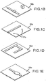
- FIG. 1 depicts a perspective view of a unit cell 100 of a microfluidic device, according to embodiments of the present invention.
- Unit cell 100 includes a first channel 130, a first isolation valve 132, a first chamber 140, a second channel 110, a second isolation valve 112, a second chamber 120, a control channel 150, an interface channel 160, an interface valve 162, and a reaction channel 170.
- these features are at least partially contained, embedded, or formed by or within an elastomeric block 180.
- first channel 130 is at least partially disposed within a first layer 181 of elastomeric block 180.
- Control channel 150 is at least partially disposed within a second layer 182 of elastomeric block 180, where the second layer is adjacent to the first layer.
- Second channel 110 is at least partially disposed within a third layer 183 of elastomeric block 180, where the third layer is adjacent to the second layer.
- Interface channel 160 is at least partially disposed within a fourth layer 184 of elastomeric block 180, where the fourth layer is adjacent to the third layer.
- a first material such as an assay reagent
- first channel 130 can flow through first channel 130, past first isolation valve 132, and into first chamber 140.
- second material such as an assay sample
- second channel 110 can flow through second channel 110, past second isolation valve 112, through via 111, and into second chamber 120.
- first and second isolation valves 132, 112, respectively are both in an open valve state.
- interface valve 162 is in a closed valve state.
- first channel 130 is in open fluid communication with first reaction chamber 140
- second channel 110 is in fluid communication with second reaction chamber 120
- fluid communication between the first and second chambers is interrupted or inhibited.
- Reaction chamber sizes may vary.
- the volume of second reaction chamber 120 is different or greater than the volume of first reaction chamber 140.
- the volume of second reaction chamber 120 can be ten times greater than the volume of first reaction chamber 140.
- Materials can be loaded into their respective chambers under pressure. Relatedly, materials can be loaded into chambers at certain concentrations. In some cases, a reagent solution is loaded into a chamber at a 10x concentration, and is then diluted when reacted with a sample solution contained in another chamber.
- control channel 150 can be activated so as to transform each of first and second isolation valves 132, 112 from an open valve state to a closed valve state. In this way the materials can be confined, optionally under pressure, within the reaction chambers.
- a single control channel for example control channel 150, can control flow of a first material into a first reaction chamber, and can also control flow of a second material into a second reaction chamber.
- Operation of a single control channel can thus act to isolate a first volume of material or solution within the first chamber via actuation of the first isolation valve 132, and can also isolate a second volume of material or solution within the second chamber via actuation of the second isolation valve 112.
- operation of a single control channel can cause a first deflection in a first direction at first isolation valve 132, and a second deflection in a second direction at second isolation valve 112, where first direction is opposite to second direction.
- the deflection in the first isolation valve can be in the upward direction
- the deflection in the second isolation valve can be in the downward direction. Accordingly, control of more than one isolation valve can be effected simultaneously by operation of the single control channel.
- first material such as a reagent can be disposed in first reaction chamber 140 at a first pressure that is within a range from about 0 Pa (0 psi) to about 103421 Pa (15 psi).
- second material such as a sample can be disposed in second reaction chamber 120 at a second pressure that is within a range from about 0 Pa (0 psi) to about 68948 Pa (10 psi).
- material can be contained in the first reaction chamber 140 at about 68948 Pa (10 psi) and material can be contained in the second reaction chamber 120 at about 0 Pa (0 psi).
- loading of the microfluidic device involves introducing material into first channel 130 or second channel 110, or both, under pressure.
- a pressurizing mechanism can be used to drive materials into the chambers.
- a microfluidic system may include a plurality of separate reaction chambers formed in a multi-layer elastomeric block.
- the system may also include a thermal transfer device proximal to or near at least one of the reaction chambers.
- the thermal transfer device can be formed to contact a thermal control source.
- Reagents for carrying out a desired reaction can be introduced into a microfluidic array device or matrix.
- the array device or matrix can be contacted with the thermal control device such that the thermal control device is in thermal communication with the thermal control source so that a temperature of the reaction in at least one of the reaction chamber is changed or controlled as a result of a change in temperature of the thermal control source.
- Exemplary thermal cycling techniques are discussed in U.S. Patent Publication No. 2007/0196912 .
- a microfluidic device or chip can be coupled with or in operative association with an Integrated Heat Spreader (IHS). Such heating mechanisms are discussed in U.S. Patent No. 7,307,802 .
- FIG. 1A shows an exploded perspective view of individual layers of a unit cell 100 of a microfluidic device, according to embodiments of the present invention.
- Each layer typically includes an elastomeric membrane with one or more recesses, channels, chambers, or the like.
- first layer 181 of unit cell 100 includes a first channel 130 in fluid communication with a first chamber 140.
- First layer 181 also includes a second chamber 120.
- Second layer 182 includes a control channel 150, a first via 111, and a second via 131.
- Third layer 183 includes a second channel 110 and a reaction channel 170.
- unit cell 100 can be configured so that second channel 110 and reaction channel 170 are in fluid communication with second chamber 120, optionally by way of via 111.
- creating a fluid passage that extends from second channel 110 to reaction channel 170 can involve removing a portion of second layer 182 that is disposed below second chamber 120. Creation of this fluid passage can also involve removing a corresponding portion of third layer 183 that is disposed below second chamber 120.
- unit cell 100 can be configured so that reaction channel 170 is in fluid communication with first chamber 140, optionally by way of via 131.
- creating a fluid passage that extends from first channel 130 to reaction channel 170 can involve removing a portion of second layer 182 that is disposed below first chamber 140. Creation of this fluid passage can also involve removing a corresponding portion of third layer 183 that is disposed below first chamber 140.
- Fourth layer 184 includes an interface channel 160.
- first channel 130 is at least partially contained within a first layer 181.
- Control channel 150, via 111, and via 131 are each at least partially contained within a second layer 182, where the second layer is adjacent to the first layer.
- Second channel 110 and reaction channel 170 are at least partially contained within a third layer 183, where the third layer is adjacent to the second layer.
- vias 131, 111 are disposed in second layer 182. It is understood that corresponding vias can be formed in third layer 183, so as to provide fluid communication from chamber 140 through via 131 and into channel 170, and fluid communication from chamber 120 through via 111 and into the intersection of channels 110 and 170.
- Interface channel 160 is at least partially contained within a fourth layer 184, where the fourth layer is adjacent to the third layer.
- First chamber 140 is at least partially contained within first layer 181.
- First chamber 140 in some instances can also be least partially contained within or in communication with passages located in second layer 182 and third layer 183, thus providing fluid communication between first chamber 140 and first channel 130, and between first chamber 140 and reaction channel 170.
- Second chamber 120 is at least partially contained within first layer 181. In some instances second chamber 120 can be at least partially contained within or in communication with passages located in second layer 182 and third layer 183, thus providing fluid communication between second chamber 120 and reaction channel 170.
- reaction channel 170 and interface valve 162 are not located within the same plane or level as first chamber 140 and second chamber 120.
- reaction channel 170 is disposed in third layer 183
- interface valve 162 operates at or near the boundary or junction between fourth layer 184 and third layer 183
- first and second chambers 140, 120 are disposed in first layer 181.
- a sidewall of first chamber 140 and a facing sidewall of second chamber 120 are separated by a distance of about 120 microns.
- a distance between facing sidewalls of first and second chambers is within a range from about 40 microns to about 225 microns.
- a first chamber sidewall and a facing second chamber sidewall can be separated by a distance of about 50 microns, about 60 microns, about 70 microns, or about 80 microns.
- interface valve 162 is about 50 microns in width.
- the distance between facing sidewalls of first and second chambers can be less than, about the same as, or more than the diameter or width of the interface valve which controls or modulates flow between the chambers. Accordingly, microfluidic devices employing such architecture can present extremely large numbers of chambers within a given area. Such high densities may be difficult to achieve in situations where a valve that controls flow between two chambers is disposed in the same layer as the chambers.
- First chamber 140 can have a width within a range from about 25 microns to about 75 microns, a length within a range from about 80 microns to about 240 microns, and a height within a range from about 30 microns to about 90 microns.
- first chamber 140 can have a volume within a range from about 0.1 nanoliters to about 10 nanoliters.
- first chamber 140 can have a width of 50 microns, a length of 162.5 microns, a height of 60 microns, and a volume of 0.49 nanoliters.
- Second chamber 120 can have a width within a range from about 70 microns to about 210 microns, a length within a range from about 80 microns to about 240 microns, and a height within a range from about 150 microns to about 450 microns.
- second chamber 120 can have a volume within a range from about 1 nanoliter to about 20 nanoliters.
- second chamber 120 can have a width of 137.5 microns, a length of 162.5 microns, a height of 300 microns, and a volume of 6.7 nanoliters.
- a microfluidic device according to embodiments of the present invention can provide a center-to-center distance between first chamber 120 and second chamber of about 300 microns. In some cases, this center-to-center distance is within a range from about 250 microns to about 350 microns. Optionally, the center-to-center distance between the first chamber and the second chamber is about 312.5 microns.
- a microfluidic device can include one or more layers that have been prepared according to spin or pour fabrication protocols.
- a spin protocol can involve placing a polymeric material on a patterned disc or mold, and spinning the disc to create a layer of polymer across the disc.
- Exemplary polymers include polymethylmethacrylate, polystyrene, polypropylene, polyester, fluoropolymers, polytetrafluoroethylene, polycarbonate, polysilicon, and polydimethylsiloxane (PDMS).
- a pour protocol can involve pouring a PDMS material, for example, on a patterned template or mold, which can result in a layer of PDMS which can be peeled or pulled off the mold intact.
- first layer 181 can be fabricated according to a pour protocol.
- PDMS can be poured onto a mold that has raised portions corresponding to the various desired fluid flow channels and chambers.
- FIG. 1B shows an exemplary mold 190b which can be used to fabricate first layer 181 of FIG. 1A . After curing, the first layer can be peeled away from the mold.
- First layer 181 can include openings, recesses, or other voids that at least partially form or define first channel 130, first chamber 140, and second chamber 120.
- FIG. 1C shows an exemplary mold 190c which can be used to fabricate second layer 182 of FIG . 1A .
- Mold 190c can also include, for example, raised or contoured portions 191c that form corresponding marks in second layer 182. These marks can be used during a laser ablation procedure, such that the laser ablation is directed toward the marks during the ablation. Mold 190c can be spun, so as to provide a thin layer of PDMS across the mold.
- Second layer 182 can include openings, recesses, or other voids that at least partially form or define control channel 150.
- second layer 182 can be exposed to one or more laser ablations.
- An ablative laser beam directed to second layer 182 can form vias 111, 131.
- first layer 181 can be aligned and contacted with the second layer.
- the first layer can adhere with the second layer, and both layers can be peeled off mold 190c simultaneously.
- PDMS can be placed onto a mold that has raised portions corresponding to the various desired containment or control channels.
- FIG. ID shows an exemplary mold 190d which can be used to fabricate third layer 183 of FIG. 1A .
- the mold can be spun, so as to provide a thin layer of PDMS across the mold.
- Third layer 183 can include openings, recesses, or other voids that at least partially form or define second channel 110 and reaction channel 170. After third layer 183 is sufficiently cured, the combined first layer 181 and second layer 182 can be aligned and contacted with the third layer. The third layer can adhere with the second layer, and all three layers can be peeled off mold 190d simultaneously.
- PDMS can be placed onto a mold that has raised portions corresponding to the various desired containment or control channels.
- FIG. 1E shows an exemplary mold 190e which can be used to fabricate fourth layer 184 of FIG. 1A . The mold can be spun, so as to provide a thin layer of PDMS across the mold.
- Fourth layer 184 can include openings, recesses, or other voids that at least partially form or define interface channel 160. After fourth layer 184 is sufficiently cured, the combined first layer 181, second layer 182, and third layer 183 can be aligned and contacted with the fourth layer. The fourth layer can adhere with the third layer, and all four layers can be peeled off mold 190e simultaneously. Optionally, the four layers can be placed on or contacted with a fifth layer 186 as shown in FIG. 1A .
- the fifth layer can include a laminate or tape, or a similarly suitable material, which operates to seal a recess in the fourth layer, so as to form or seal interface channel 160.
- the fifth layer can act as a sealing layer.
- the fifth layer may include an elastomeric material, such as PDMS.
- the fifth layer can include a rigid or hard material such as glass, silicon, or a plastic such as polystyrene.
- the fifth layer may, for example, seal recesses formed in bottom of the fourth layer, so as to provide channels in the fourth layer.
- the sealing layer can include a film which may be attached to the fourth layer via an adhesive. Hence, the sealing layer can form channels from recesses molded or machined into an adjacent layer.
- the sealing layer can be a transparent material, for example, polystyrene, polycarbonate, or polypropylene.
- the sealing layer can be flexible, such as an adhesive tape, and may be suitable for attachment to a substrate by bonding, such as with adhesive or heat sealing, or mechanically attached such as by compression.
- materials used to fabricate a sealing layer are compliant to form fluidic seals with each recess to form a fluidic channel with minimal leakage.
- a sealing layer may further be supported by an additional support layer that is rigid (not shown). In some cases, a sealing layer is rigid.
- passages or vias can be formed between channels or chambers at one layer and channels or chambers at another layer.
- a via 131 through second layer 182 to provide fluid communication between first chamber 140 in first layer 181 and reaction channel 170 in third layer 183.
- a via 111 through second layer 182 to provide fluid communication between second chamber 120 in first layer 181 and second channel 110 and reaction channel 170 in third layer 183.
- creation of these vias can enlarge the volume of the reaction chambers.
- the vias can be formed by using a laser punch to remove or ablate portions of elastomeric membrane. As shown in FIG.
- reaction chambers 120, 140 can have an interior space that extends above a plane defined by the top of first channel 130. This interior space can also extend above a plane defined by the top of second channel 110, and above a plane defined by the top of reaction channel 170.
- fluid can flow through first channel 130 and upward into the interior of first chamber 140.
- fluid can flow through second channel 110 and upward into the interior of second chamber 120, optionally through a via formed in the second layer.
- fluid can flow from the interior of first chamber 140 and downward into reaction channel 170, optionally through a via 131 formed in the second layer.
- fluid can flow from reaction channel 170 and upward into the interior of second chamber 120, optionally through a via 111 formed in the second layer.
- the second, third, fourth, and fifth layers can be processed or laser punched as part of a procedure that forms a loading passage to first channel 130 in first layer 181.
- the fourth and fifth layers can be processed or laser punched as part of a procedure that forms a loading passage to second channel 110 in third layer 183.
- Loading passages, vias, and the like can be formed using a drilling or ablation mechanism.
- a loading passage or via can be fabricated by ablating a portion of the elastomeric block.
- Excimer lasers are well suited for such ablation techniques, as they can produce a laser beam which removes a portion of the elastomeric block.
- loading passages or vias, or portions thereof can be formed before one or more of the individual layers are adhered together.
- a portion of a loading passage or via can be formed in a layer during the molding process, or after the molding process and before the adhesion process.
- formation of at least a portion of the loading passage or via can involve etching one or more elastomeric layers prior to forming the complete multilayer elastomeric block.
- fabrication methods include forming a first elastomeric layer on top of a first micromachined mold, where the first micromachined mold has one or more raised protrusions that form one or more recesses along a bottom surface of the first elastomeric layer.
- Methods may also include forming a second elastomeric layer on top of a second micromachined mold, where the second micromachined mold has one or more raised protrusions that form one or more recesses along a bottom surface of the second elastomeric layer.
- Methods may include bonding or adhering the bottom surface of the first elastomeric layer onto a top surface of the second elastomeric layer such that a channel or chamber forms in a recess between the first and second elastomeric layers. Any desired number of layers can be fabricated in this way. Methods also include positioning the last or final elastomeric layer on top of a planar substrate such that a channel or chamber forms in a recess between the final elastomeric layer and the planar substrate. Embodiments of the present invention encompass multilayer microfluidic devices having any desired elastomeric valve or pump configuration which includes such channels or chambers. Exemplary elastomeric valve and pump fabrication techniques are described in U.S. Patent No. 6,408,87 .
- Microfluidic device embodiments of the invention can be constructed out of any material or combination of materials that can be fabricated to have microfluidic channels and chambers, and valves that regulate flow through channels and into chambers.
- Materials from which a device can be fabricated include, without limitation, elastomers, silicon, glass, metal, polymer, ceramic, inorganic materials, and/or combinations of these materials.
- the methods used in fabrication of a microfluidic device may vary with the materials used, and include soft lithography methods, microassembly, bulk micromachining methods, surface micro-machining methods, standard lithographic methods, wet etching, reactive ion etching, plasma etching, stereolithography and laser chemical three-dimensional writing methods, modular assembly methods, replica molding methods, injection molding methods, hot molding methods, laser ablation methods, combinations of methods, and other methods known in the art or developed in the future.
- the device is fabricated using elastomeric materials. Fabrication methods using elastomeric materials and methods for design of devices and their components have been described in detail in the scientific and patent literature. See, e.g., Unger et al., 2000, Science 288:113-16 ; U.S. Pat. Nos.
- Embodiments of the present invention further encompass aspects of microfluidic fabrication and production, as well as microfluidic device operation and use, as disclosed in U.S. Patent Application No. 12/018,138 filed January 22, 2008 .
- elastomeric material is placed on a wafer or mold, and allowed to cure.
- the elastomeric material can include one or more polymers incorporating materials such as chlorosilanes or methyl-, ethyl-, and phenylsilanes, and polydimethylsiloxane (PDMS) such as Dow Chemical Corp.
- PDMS polydimethylsiloxane
- Sylgard 182, 184 or 186, or aliphatic urethane diacrylates such as (but not limited to) Ebecryl 270 or Irr 245 from UCB Chemical may also be used.
- the elastomeric material is deposited on the wafer or mold in a spin coating process, a spray coating process, a dip coating process, a screen printing process, an inkjet deposition process, or the like.
- the curing procedure can involve baking or room temperature vulcanizing (RTV), photocuring, and the like.
- An elastomeric composition may include multiple parts, which can be mixed together at various ratios to obtain desired bond properties.
- an elastomeric material may include a Part A and a Part B, which when mixed together in prescribed amounts facilitates the desired bond parameters.
- the parts may be mixed in a ratio within a range from about 3:1 to about 30:1.
- an elastomeric PDMS composition is baked to provide a 10:1 RTV layer.
- a photoresist material can be placed on the cured elastomeric material.
- an SU-8 resist available from MicroChem Corp., Newton MA
- Exemplary SU-8 resists include SU-8 2000, SU-8 3000, SU-8 2007, SU-8 3005, and the like.
- the photoresist can be deposited on the elastomeric material in a spin coating procedure, at a desired rotational speed and duration.
- the spin coating can be performed at a rotational speed within a range from about 1000 to about 10,000 rpm, and for a duration within a range from about 20 seconds to about 2,000 seconds.
- the spin coating can be performed at 5000rpm for 200 seconds.
- the photoresist mask can have a thickness or depth within a range from about 0.5 to about 50 microns. In some cases, the thickness is about 5 microns.
- the thickness of the mask can be selected for facile via opening formation, and the selected spin time can eliminate or inhibit beading of the photoresist material.
- the photoresist material can be used as an etch mask.
- the photoresist can be processed at a selected temperature for a selected time duration.
- the photoresist is soft baked at a temperature within a range from about 45°C to about 85°C.
- the photoresist can be baked for a duration within a range from about 1 minute to about 10 minutes. In some cases, the soft bake is performed for 5 minutes at 65°C.
- Such preparation techniques can help to eliminate or inhibit photoresist mask cracking at exposure.
- the preparation procedure may also include cooling the photoresist.
- the photoresist may be cooled at room temperature or at a temperature within a range from about 18°C to about 37°C, and for a duration within a range from about 3 minutes to about 300 minutes. In some cases, the photoresist is cooled for about 30 minutes.
- the lithography procedure can involve multiple exposure steps. For example, a first exposure step can be performed with a first exposure mask, and a second subsequent exposure step can be performed with a second exposure mask.
- An exposure step can involve the application of radiation or energy, through an exposure mask, toward a photoresist.
- Exposure radiation can include ultraviolet light, near ultraviolet light, deep ultraviolet light, visible light, infrared light, or energy at any desired wavelength along the electromagnetic spectrum. In some cases, exposure radiation is delivered at one or more wavelengths within a range from about 10 to about 10 -9 cm.
- the type of radiation or energy is selected based on the composition of the photoresist. For example, specific types of radiation or energy can be applied to I-line photoresists, G-line photoresists, H-line photoresists, and the like.
- the use of multiple masks can help to prevent or inhibit the effect of contaminants on a mask from replicating on the photoresist. For example, if there is an unwanted particle on the first mask at a certain location, exposure with a second mask can help to ensure exposure of the photoresist at that location.
- the exposure process can be followed with a post-exposure bake (PEB) procedure.
- PEB post-exposure bake
- a PEB procedure is performed for a duration within a range from about 0 to about 200 minutes, and at a temperature within a range from about 50°C to about 80°C.
- a PEB can be performed for 2 minutes at 65°C.
- the PEB can operate to cross-link the photoresist mask material, rendering the material nonsoluble.
- the exposed photoresist can be allowed to cool.
- An exemplary cooling process is performed at a temperature within a range from about 18°C to about 37°C for a duration within a range from about 1 hour to about 40 hours. In some cases, the exposed photoresist is cooled at room temperature for about 18 hours.
- a development process can be performed following exposure.
- the photoresist mask is developed for a duration within a range from about 10 seconds to about 10 minutes.
- a developer is applied to the exposed photoresist.
- the developer can include, for example, an organic solvent such as acetate. It is understood that the developer or solvent may be selected based on the composition of the photoresist.
- the developer can operate to dissolve or degrade areas or locations of the photoresist layer that were unexposed or masked during the exposure process.
- the photoresist mask is subject to a drying procedure. For example, the mask can be spin-dried.
- the mask may also be allowed to relax for a desired period of time. In some cases, the mask is allowed to relax at or near room temperature for a duration within a range from about 1 minute to about 48 hours.
- additional elastomeric layers can be spin-coated or otherwise applied onto the developed photoresist.
- an RTV coating have a thickness or depth within a range from about 0.3 microns to about 30 microns can be deposited on the photoresist mask.
- the elastomeric coating can be baked for a duration within a range from about 5 minutes to about 3 hours, at a temperature within a range from about 40°C to about 80°C.
- a 3 micron RTV coating is spin-coated on an SU-8 mask, and baked for 1 hour at 60°C.
- Such techniques can help to minimize lateral etch, and reduce via size nonuniformity.
- the RTV layer can be deposited on a patterned photoresist layer, to help prevent or inhibit the formation of pinholes in the underlying elastomer.
- etching involves removing certain areas of the elastomeric material that are not protected by the photoresist following development.
- etching can be performed for a duration within a range from about 1 minute to about 20 minutes and at a temperature within a range from about 50°C to about 90°C.
- etching can be carried out in an 80% tetrabutylammonium fluoride (TBAF) etchant solution for 6-8 minutes at 70 degrees °C.
- TBAF tetrabutylammonium fluoride
- etching is performed in an ultrasonic bath tank, optionally in degas mode. Such procedures can help to ensure a uniform etching depth, with minimum damage to a photoresist mask during the etching procedure.
- Etching can be followed with a deionized water wash. In some cases, a hot water wash is performed for three minutes. The photoresist mask can be removed with adhesive tape. A deionized water wash can be applied again, optionally for 3 minutes. Stacking procedures can provide additional layers to the elastomer. In some cases, adjacent layers adhere to one another by way of interlayer bonding.
- FIG. 2 illustrates another perspective view of unit cell 100.
- the first material can flow from first reaction chamber 140, through via 131, through reaction channel 170, past interface valve 162, through via 111, and into second reaction chamber 120, where the first material can contact the second material.
- the second material can flow from second reaction chamber 120, through via 111, through reaction channel 170, past interface valve 162, through via 131, and into first reaction chamber.
- the interface channel 160 can be activated so as to transform interface valve 162 from a closed valve state to an open valve state. Under such conditions, the first and second reaction chambers 140, 120 are in open fluid communication by way of the reaction channel and the vias.
- the pressure differential can help to release or open interface valve 162.
- a pressure differential can facilitate mixing between the first material and the second material, as the first material is forcefully expelled from first chamber and into second chamber, thus squirting a stream of first material into a second material contained in the second chamber, where the first material can diffuse into or permeate through the second material.
- the presence, absence, or extent of any reaction between the first and second materials, or involving either or both of the first and second materials, within the second reaction chamber can be characterized, confirmed, detected, or quantified by inspection, for example with a reader, sensor, or imaging device 190.
- An imaging device 190 can include a camera, optionally having a charge-coupled device (CCD), that detects or monitors energy that emits from the chamber. In some cases, the imaging device can detect emission intensity output. Exemplary imaging devices and reader techniques suitable for use with embodiments of the present invention are described in U.S. Patent No. 7,307,802 issued December 11, 2007 . In some cases, a reaction within a chamber is facilitated by a thermal cycler. Embodiments of the present invention encompass systems and methods for mixing or reacting materials within chambers, where such mixing or reacting procedures involve any of a variety of desired thermal cycling heating protocols or thermal gradient modalities.
- FIG. 3 illustrates a perspective view of a matrix 300 having four unit cells 300 (1,1) , 300 (1,2) , 300 (2,1) , and 300 (2,2) arranged in two rows and two columns.
- Matrix 300 includes a plurality of first channels 330 (1) , 330 (2) , a plurality of first isolation valves 332 (1,1) , 332 (1,2) , 332 (2,1) , 332 (2,2) , a plurality of first chambers 340 (1,1) , 340 (1,2) , 340 (2,1) , 340 (2,2) , a plurality of second channels 310 (1) , 310 (2) , a plurality of second isolation valves 312 (1,1) , 312 (1,2) , 312 (2,1) , 312 (2,2) , a plurality of second chambers 320 (1,1) , 320 (1,2) , 320 (2,1) , 320 (2,2) , a plurality of control channels 350 (1) , 350 (2) , a
- a matrix can include 9216 unit cells arranged in 96 rows and 96 columns.
- embodiments of the present invention provide a high density format for reacting a plurality of samples with a plurality of reagents, for example, ninety-six (96) samples with ninety-six (96) reagents.
- Microfluidic device features such as channels, valves, chambers, are often at least partially contained, embedded, or formed by or within one or more layers of an elastomeric block 380.
- a first material such as a reagent can flow through a first channel 330 (1) , past or through a plurality of first isolation valves 332 (1,1) , 332 (1,2) , and into a plurality of first chambers 340 (1,1) , 340 (1,2) , respectively.
- a second material such as a reagent can flow through a first channel 330 (2) , past or through a plurality, of first isolation valves 332 (2,1) , 332 (2,2) , and into a plurality of first chambers 340 (2,1) , 340 (2,2) , respectively.
- materials flow through first channel 330 (1) and first channel 330 (2) in the same direction.
- material flowing through first channel 330 (1) travels in a direction opposite from material flowing through first channel 330 (2) .
- a third material such as a sample can flow through a second channel 310 (1) , past or through a plurality of second isolation valves 312 (1,1) , 312 (2,1) , and into a plurality of second chambers 320 (1,1) , 320 (2,1) , respectively.
- embodiments of the present invention provide microfluidic techniques whereby a material can be flowed through a common passage or trunk of a channel, such as second channel 310 (1) , and into a plurality of individual branches stemming from the common trunk, such as those branch channels which individually feed into second chambers 320 (1,2) , 320 (2,2) .
- a fourth material such as a sample can flow through a second channel 310 (2) , past or through a plurality of second isolation valves 312 (1,2) , 312 (2,2) , and into a plurality of second chambers 320 (1,2) , 320 (2,2) , respectively.
- materials flow through second channel 310 (1) and second channel 310 (2) in the same direction.
- material flowing through second channel 310 (1) travels in a direction opposite from material flowing through second channel 310 (2) . As shown in FIG. 3 , material flowing through second channel 310 (1) and material flowing through second channel 310 (2) travel in opposing directions "B1" and "B2", respectively.
- some samples can be introduced through routing lines on one side of the block, and some samples can be introduced through routing lines on an opposing side of the block. This allows for an even distribution or placement of sample loading route lines on opposite sides of the block, instead of placing all or most sample loading route lines on the same side of the block. Because the sum total of the sample routing lines are divided between different sides of the block, more sample routing lines can be introduced into the block. Consequently, a greater number of samples can be analyzed within the block during a single procedure.
- each of the plurality of first isolation valves 332 (1,1) , 332 (1,2) , 332 (2,1) , 332 (2,2) is in an open valve state.
- each of the plurality of second isolation valves 312 (1,1) , 312 (1,2) , 312 (2,1) , 312 (2,2) is in an open valve state.
- each of the plurality of interface valves 362 (1,1) , 362 (1,2) , 362 (2,1) , 362 (2,2) , respectively, is in a closed valve state.
- first channel 330 (1) is in fluid communication with first reaction chambers 340 (1,1) , 340 (1,2)
- first channel 330 (2) is in fluid communication with first reaction chambers 340 (2,1) , 340 (2,2)
- second channel 310 (1) is in fluid communication with second reaction chambers 320 (1,1) , 320 (2,1)
- second channel 310 (2) is in fluid communication with second reaction chambers 320 (1,2) , 320 (2,2) .
- Fluid communication between first chambers 340 (1,1) , 340 (1,2) , 340 (2,1) , 340 (2,2) and second chambers 320 (1,1) , 320 (1,2) , 320 (2,1) 320 (2,2) , respectively, is interrupted.
- a first material can be loaded into first reaction chambers 340 (1,1) , 340 (1,2) via first channel 330 (1) .
- a second material can be loaded into first reaction chambers 340 (2,1) , 340 (2,2) via first channel 330 (2) .
- a third material can be loaded into second reaction chambers 320 (1,1) , 320 (2,1) via second channel 310 (1) .
- a fourth material can be loaded into second reaction chambers 320 (1,2) , 320 (2,2) via second channel 310 (2) .
- such materials can be loaded into the chambers under a desired or selected pressure.
- Control channel 350 (1) can be activated so as to transform each of first isolation valves 332 (1,1) , 332 (2,1) and second isolation valves 312 (1,1) , 312 (2,1) from an open valve state to a closed valve state.
- control channel 350 (2) can be activated so as to transform each of first isolation valves 332 (1,2) , 332 (2,2) and second isolation valves 312 (1,2) , 312 (2,2) from an open valve state to a closed valve state. In this way the materials can be confined or maintained, optionally under pressure, within the reaction chambers.
- FIG. 4 illustrates another perspective view of matrix 300 having four unit cells 300 (1,1) 300 (1,2) , 300 (2,1) , 300 (2,2) .
- the first material can flow from first reaction chamber 340 (1,1) , through reaction channel 370 (1,1) , past interface valve 362 (1,1) , and into second reaction chamber 320 (1,1 ), where the first material can contact the third material.
- the interface channel 360 (1) can be activated so as to transform interface valve 362 (1,1) from a closed valve state to an open valve state. Under such conditions, first reaction chamber 340 (1,1) and second reaction chamber 320 (1,1) are in fluid communication via reaction channel 370 (1,1) .
- the presence, absence, or extent of any reaction between the first and third materials within second reaction chamber 320 (1,1) can be confirmed, detected, or quantified by inspection, for example with a reader or sensor 390.
- the first material can flow from first reaction chamber 340 (1,2) , through reaction channel 370 (1,2) , past interface valve 362 (1,2) , and into second reaction chamber 320 (1,2) , where the first material can contact the fourth material.
- the interface channel 360 (1) can be activated so as to transform interface valve 362 (1,2) from a closed valve state to an open valve state.
- first reaction chamber 340 (1,2) and second reaction chamber 320 (1,2) are in fluid communication via reaction channel 370 (1,2) .
- the presence, absence, or extent of any reaction between the first and third materials within second reaction chamber 340 (1,2) can be confirmed, detected, or quantified by inspection, for example with a reader or sensor 390.
- the second material can flow from first reaction chamber 340 (2,1) , through reaction channel 370 (2,1) , past interface valve 362 (2,1) , and into second reaction chamber 320 (2,1) , where the second material can contact the third material.
- the interface channel 360 (2) can be activated so as to transform interface valve 362 (2,1) from a closed valve state to an open valve state.
- first reaction chamber 340 (2,1) and second reaction chamber 320 (2,1) are in fluid communication via reaction channel 370 (2,1) .
- the presence, absence, or extent of any reaction between the first and third materials within second reaction chamber 320 (2,1) can be confirmed, detected, or quantified by inspection, for example with a reader or sensor 390.
- the second material can flow from first reaction chamber 340 (2,2) , through reaction channel 370 (2,2) , past interface valve 362 (2,2) , and into second reaction chamber 320 (2,2) , where the second material can contact the fourth material.
- the interface channel 360 (2) can be activated so as to transform interface valve 362 (2,2) from a closed valve state to an open valve state.
- first reaction chamber 340 (2,2) and second reaction chamber 320 (2,2) are in fluid communication via reaction channel 370 (2,2) .
- the presence, absence, or extent of any reaction between the fourth and second materials within second reaction chamber 320 (2,2) can be confirmed, detected, or quantified by inspection, for example with a reader or sensor 390.
- isolation valve and containment valve may be used interchangeably.
- interface valve and reaction valve may be used interchangeably.
- Such valves can be actuated or activated or otherwise controlled by any of a variety of valve operation methods or configurations. Exemplary valve systems and techniques which are well suited for use with embodiments of the present invention are described, for example, in U.S. Patent No. 6,408,878 , the content of which is incorporated herein by reference. Often, such valves include an elastomeric portion that, when actuated, deflects into a recess.
- FIG. 5A shows a side view or cross section of a microfluidic device unit cell 500.
- the unit cell includes a first channel 530 and first sample chamber 540 in a first layer 581 of an elastomeric block 580, control channel 550 and via 511 a in a second layer 582, and a reaction channel 570 in a third layer 583.
- An isolation valve 532 can be actuated, so as to inhibit or prevent flow through first channel 530. Actuation of isolation valve 532 can involve the deflection of an elastomeric portion 532a into a recess 531 of first channel 530.
- Fourth layer 584 includes interface channel 560.
- FIG. 5B shows another side view or cross section of microfluidic device unit cell 500.
- the unit cell includes a sample chamber 520 in a first layer 581, a control channel 550 and via 531b in a second layer 582, and a second channel 510 in a third layer 583.
- Isolation valve 512 can be actuated, so as to inhibit or prevent flow through second channel 510. Actuation of isolation valve 512 can involve the deflection of an elastomeric portion 512a into a recess 511 of second channel 510.
- FIG. 5C shows a side view or cross section which is orthogonal to the side views of FIGS. 5A and 5B . As depicted here, actuation of control channel 550 can operate to activate both isolation valve 532 and isolation valve 512.
- first channel 530 and second channel 510 each present a rectangular cross section. In some instances, either or both of these channels can present a dome shaped cross section, where the dome is upright with regard to first channel 530 and inverted with regard to second channel 510.
- FIG. 6A illustrates a microfluidic device 699 according to embodiments of the present invention.
- Materials can be delivered from wells 605 toward elastomeric block 608 through passages or routing lines 601.
- FIG. 6B depicts microfluidic device 699 in a plan view.
- Microfluidic device 699 includes a substrate 600 with integrated pressure accumulator wells 601 and 602, each having a receptacle 603, 604 that contains a valve, such as a check valve.
- Microfluidic device 699 also includes one or more wells 605 for receiving materials such as samples or reagents, and one or more channels or routing lines disposed between wells 605 and an elastomeric block location 607 of substrate 600.
- An elastomeric block 608 can be coupled with substrate 600 at elastomeric block location 607.
- Elastomeric block can include one or more layers of elastomeric material having microfabricated recesses or channels formed therein.
- Elastomeric block 608 can be coupled with substrate 600 in any of a variety of ways.
- the elastomeric block can be attached or bonded with the substrate.
- the block is directly bonded to the substrate.
- the block is coupled with the substrate without the use of an adhesive.
- the block is coupled with the substrate with an adhesive.
- Within elastomeric block 608 are one or more channels in fluid communication with one or more vias 614, which in turn provide fluid communication between the elastomeric block channels and the substrate channels.
- the substrate channels can provide fluid communication between wells 605 and channels within the elastomeric block.
- valves 611,612, respectively which can be check valves for introducing and holding gas of fluid under pressure into accumulator chambers 615 and 616.
- Valves 611 and 612 are situated inside of receptacles 604 and 603, respectively, which can keep liquid, when present in accumulator chambers 615 and 616, from contacting valves 611 and 612.
- valves 611 and 612 may be mechanically opened by pressing a shave, pin or the like, within a check valve to overcome a self closing force of the check valve, thereby permitting release of pressure from the accumulator chamber, or reducing fluid pressure contained within the accumulator chamber.
- Substrate 600 and associated components may be fabricated from polymers, such as polypropylene, polyethylene, polycarbonate, high-density polyethylene, polytetrafluoroethylene PTFE or Teflon®, glass, quartz, transparent materials, polysilicon, metals, such as aluminum, or the like. Any of a variety of gases, liquids, or fluids can be introduced into accumulator chambers 615 and 616. In some cases, valves 611 and 612 can be actuated to release fluid pressure otherwise held inside of accumulator chambers 615 and 616. Optionally, a portion of substrate 600 beneath the elastomeric block region 607 can be transparent. In some cases, the portion may be opaque or reflective.
- Accumulator chambers 601 and 602 can be in fluid communication with channels contained in elastomeric block region 607, and ultimately, with channels contained in elastomeric block 608. Accumulator operation is described in U.S. Patent Publication No. 2007/0196912 , the content of which is incorporated herein by reference. In some cases, operation of a channel, such as a control channel 150 as shown in FIG. 1 , can be modulated or controlled by an accumulator.
- FIG. 7 illustrates a microfluidic device 700 according to embodiments of the present invention.
- Device 700 includes a carrier 710 coupled with a chip or block 750.
- Carrier or frame 710 includes a plurality of routing lines 712 configured to allow flow from carrier wells toward chip 750.
- routing lines disposed on the "S" side of the carrier can provide for the passage of sample
- routing lines disposed on the "R" side of the carrier can provide for the passage of reagent.
- chip 750 can also include a plurality of routing lines 752.
- routing lines on the chip can provide material transport on the chip from location A to location B, and from location C to location D.
- a portion of the samples loaded onto the carrier can be transported to location E of the chip, and another portion of the samples loaded onto the carrier can be transported to locations D and B of the chip, such that some sample is loaded at one side of the block, and some sample is loaded at an opposing side of the block, as further discussed herein with reference to FIG. 3 .
- FIG. 8 illustrates a microfluidic device 800 according to embodiments of the present invention.
- Device 800 includes a carrier 810 coupled with a chip or block 850.
- Carrier or frame 810 includes a plurality of routing lines 812 configured to allow flow from carrier wells toward chip 850.
- routing lines disposed on the "S" side of the carrier can provide for the passage of sample
- routing lines disposed on the "R" side of the carrier can provide for the passage of reagent.
- 24 samples loaded into wells at zone S 1 flow to the left side of the chip (upper half)
- 24 samples loaded into wells at zone S 2 flow to the upper side of the chip (left half)
- 24 samples loaded into wells at zone S 3 flow to the upper side of the chip (right half)
- 24 samples loaded into wells at zone S 4 flow to the right side of the chip (upper half).
- the S 1 samples flow to the left side of the chip (lower half)
- the S 2 samples flow to the left side of the chip (upper half)
- the S 3 samples flow to the right side of the chip (upper half)
- the S 4 samples flow to the right side of the chip (lower half).
- 24 reagent portions loaded into wells at zone R 1 flow to the left side of the chip (lower half)
- 24 reagent portions loaded into wells at zone R 2 flow to the lower side of the chip (left half)
- 24 reagent portions loaded into wells at zone R 3 flow to the lower side of the chip (right half)
- 24 reagent portions loaded into wells at zone R 4 flow to the right side of the chip (lower half).
- routing lines on or in the chip can provide material transport on or through the chip from one location to another. In this way, a portion of the samples loaded at one end of the carrier (e.g. the "S" end) can be transported such that some sample is loaded at one side of the block, and some sample is loaded at an opposing side of the block, as further discussed herein with reference to FIG. 3 .
- microfluidic devices may contain blind flow channels which include a region that functions as a reaction chamber or reaction site.
- Blind flow or blind fill, can refer to the filling of a dead-end tube or lumen with a liquid where a head of gas is pushed in front of the liquid bolus, and where that head of gas is vented or otherwise released from the lumen, allowing the dead-end lumen to fill fully with the liquid.
- polydimethylsiloxane (PDMS) can be used as an elastomeric material. PDMS is sufficiently gas permeable that liquid pressurized at a few psi can drive the gas out of the channels, leaving them completely filled with liquid.
- Table 1 provides an exemplary experimental design where various materials can be loaded or introduced into a microfluidic device that includes four unit cells. According to this table, sample can be flowed through first channels and reagent can be flowed through second channels. It is understood that alternatively, reagent can be flowed through first channels and sample can be flowed through second channels. Embodiments of the present invention encompass techniques were sample is flowed through a set of first channels and a set of second channels, and reagent is flowed through a set of first channels and a set of second channels.
- Table 1 channel material chamber first channel 330 (1) DNA sample from person A first chambers 340 (1,1) , 340 (1,2) first channel 330 (2) DNA sample from person B first chambers 34 0(2,1) , 340 (2,2) second channel 310 (1) disease X gene primers/probes second chambers 320 (1,1) , 320 (2,1) second channel 310 (2) disease Y gene primers/probes second chambers 320 (1,2) , 320 (2,2)
- Table 2 shows the mixtures occurring in the microfluidic device reaction chambers, and the experimental inquiries which can be answered, for example, by conducting a PCR reaction where the sample contains patient DNA and the reagent contains an oligonucleotide primer and probe set.
- Table 2 reaction chamber materials mixed inquiry second chamber 320 (1,1) DNA sample from person A disease X gene primer/probe person A has gene for disease X? second chamber 320 (1,2) DNA sample from person A disease Y gene primer/probe person A has gene for disease Y? second chamber 320 (2,1) DNA sample from person B disease X gene primer/probe person B has gene for disease X? second chamber 320 (2,2) DNA sample from person B disease Y gene primer/probe person B has gene for disease Y?
- a method includes providing a microfluidic device having a first chamber having a dimension between 1000 ⁇ m and 1 ⁇ m, a second chamber having a dimension between 1000 ⁇ m and 1 ⁇ m, and one or more flow or control channels each having a dimension between 1000 ⁇ m and 1 ⁇ m.
- the first and second chambers can be in fluid communication with each other through a channel.
- a valve can be disposed along a channel which, when actuated to open or close, controls fluid communication between the first and second chambers, or into or out of the first or second chamber, or both.
- the method can include introducing a crystallization reagent into the first chamber, introducing the protein in a solution into the second chamber, opening a valve so that the solution containing the protein in the second chamber becomes in fluid communication with the crystallization reagent in the first chamber, and closing the valve after a period of time to interrupt fluid communication between the first and second chambers.
- a valve can be under the control of an automated valve actuating device, which in turn may be further under control of a computer or processor.
- a multilayer microfluidic device can include at least one elastomeric layer, and a valve can include a deflectable membrane.
- a deflectable membrane of a valve can be deflectable into one or more channels to control fluid movement along the channels.
- Multiple elastomeric membranes may be bonded or adhered together to form an elastomeric block.
- portions of channels or chambers can overlap with portions of other channels or chambers at an overlap region. Such channels or chambers can be in fluid communication through a via located at the overlap region.
- FIGS. 9-13 disclose additional aspects of microfluidic systems and methods according to embodiments of the present invention.
- FIG. 9 shows a photomicrograph, with scale bar, of an exemplary microfluidic device.
- FIGS. 10-12 each show reader images of exemplary microfluidic devices and experimental results provided by the devices.
- FIG. 13 illustrates an exemplary microfluidic device, showing channel connections between input wells and an elastomeric block.
- a microfluidic system can include a microfluidic device having a multiwell plate, optionally referred to as a carrier or frame. Often, the multiwell plate includes a plastic material, such as an injection molded plastic.
- the multiwell plate can include channel connections or passages for providing fluid communication between input wells and an elastomeric block.
- U.S. Patent Application No. 61/030,887 filed February 22, 2008 which is incorporated herein by reference, describes carrier or frame configurations which are suitable for use with microfluidic systems and methods of the instant application.
- FIG. 14 shows further aspects of microfluidic systems and methods according to embodiments of the present invention.
- Additional embodiments of the invention include methods for detecting nucleic acid analytes through their interactions with a nucleic acid probe, such as a hydrolysis probe, a hairpin probe, a padlock probe (PLP) or a hybridization probe.
- the methods of the invention combine the features of using the high throughput microfluidic device as described herein, labeled nucleic acid probes, and homogenous assays to detect and/or quantify nucleic acid analytes with high PCR and probe specificity. Certain methods described herein may allow for the detection of low copy number nucleic acid analyte per cell, have low fluorescence background yielding a high signal to noise ratio.
- the homogeneous assays of the invention may have a dynamic range of at least about 3 orders of magnitude, more often at least about 4, even more often at least about 5, even more often at least about 6, often at least about 7, and sometimes at least about 8 orders of magnitude.
- the detection and/or quantification of a plurality of nucleic acid analytes from a sample may generally be carried out by obtaining a pre-amplified sample, aliquoting the sample and distributing the pre-amplified sample into reaction chambers of a microfluidic device containing the appropriate buffers, primers, probes and enzymes, performing a homogenous assay for the target nucleic analytes of interest, and querying the aliquots for the presence of nucleic acid analytes.
- a sample is obtained which is suspected of containing the target nucleic acid analyte of interest.
- the sample may be first reversed transcribed into cDNA and subjected to a preliminary amplification reaction to generate a pre-amplified sample.
- the reverse transcribed sample is subjected to 14 cycles of PCR in order to increase the nucleic acid analytes by about 16,000 fold.
- aliquots of the pre-amplified sample are distributed into separated compartments of a microfluidic device and combined with the appropriate reagents.
- the aliquot may have a volume of in the range of about 1 picoliter to about 500 nanoliters, more often in the range of about 100 picoliters to about 20 nanoliters, even more often in the range of about 1 nanoliter to about 20 nanoliters, and most often in the range of about 5 nanoliters to about 15 nanoliters.
- the reagents may include a labeled nucleic acid probe, PCR primers (e.g., forward primers and reverse primers), a thermostable DNA polymerase, GT buffer, an aqueous buffer, magnesium chloride and deoxynucleotide truphosphates, and may also include other non-reactive ingredients.
- PCR primers e.g., forward primers and reverse primers
- thermostable DNA polymerase e.g., forward primers and reverse primers
- GT buffer e.g., an aqueous buffer
- magnesium chloride and deoxynucleotide truphosphates e.g., magnesium chloride and deoxynucleotide truphosphates
- a pre-sample mix may be prepared which may include TaqMan Universal PCR master Mix, AmpliTaq-Gold (about 5 units/ ⁇ l), 20x GT buffer, and H 2 O.
- the pre-sample mix may be combined with the nucleic acid of interest
- a 1x GT buffer may contain betaine in a range of about 0.1 M to about 0.8 M, BSA in a range of about 1 mg/ml to about 4 mg/ml, glycerol in a range of about 1% to about 5%, PEG 20,000 in a range of about 1% to about 5%, PEG MME550 in a range of about .05 % to about 5%, MME5000 in a range of 1% about to about 5%, Superblock® in PBS in a range of about 1% to about 15%, Superblock® T20 in a range of about 1% to about 10%, and Tween 20 in a range of 0.1% about to about 3%.
- the 1x GT buffer may contain about 0.4 M betaine, 2 mg/ml BSA, about 2.5% glycerol, about 2% PEG 20,000, about 1% PEG MME550, about 2.5% MME5000, about 10% Superblock® in PBS, about 5% Superblock® T20, and about 0.5% Tween 20.
- the 1x GT buffer may contain about 0.4 M betaine, 4 mg/ml BSA, about 5% glycerol, about 2% PEG 20,000, about 1% PEG MME550, about 2.5% MME5000, about 10% Superblock® in PBS, about 10% Superblock® T20, and about 1% Tween 20.
- a 20x GT buffer may be prepared and may be diluted to a final concentration of 1x when used in the dynamic arrays.
- a 20x GT buffer may include betaine in a range of about 1M to about 10M, BSA in a range of about 5 mg/ml to about 15 mg/ml, and Superblock® T20 (in TBS) in a range of about 20% to about 65%.
- the GT buffer may include about 5 M betaine, about 10 mg/ml BSA, and about 57% Superblock®T20 in TBS.
- the 20x GT buffer would be diluted to 1x in the final reaction mix.
- the PCR primers must be sufficiently long to prime the synthesis of extension products in the presence of the agent for polymerization.
- the exact length and composition of the primer will depend on many factors, including temperature of the annealing reaction, source and composition of the primer, proximity of the probe annealing site to the primer annealing site, and ratio of primer:probe concentration.
- the oligonucleotide primer typically contains in the range of about 15 to about 30 nucleotides, although it may contain more or fewer nucleotides.
- the primers should be sufficiently complementary to selectively anneal to their respective strands and form stable duplexes.
- One skilled in the art appreciates how to select appropriate PCR primer pairs to amplify the target nucleic acid analyte of interest.
- a homogenous assay may be performed such as real-time PCR, for example.
- the labeled nucleic acid probe contains a stretch of nucleic acid sequences that are capable of recognizing 8-mer and 9-mer motifs in the target nucleic acid analyte, as described above. FRET quenching of the labeled nucleic acid probe is irrevocably eliminated when the Taq polymerase reaches the region where the labeled probe is annealed to the target nucleic acid analyte, recognizes the probe-template hybrid as a substrate, and subsequently hydrolyzes phosphodiester bonds of the probe during primer-directed DNA amplification.
- the hydrolysis reaction irrevocably releases the quenching effect of the quencher dye on the reporter dye, thus resulting in increasing detector fluorescence with each successive PCR cycle. It will be appreciated that the invention is not limited to the use of real-time PCR, and that other variations of PCR, described above, may be used to detect and/or quantify the analyte of interest.
- the homogenous assay of the invention should not be construed to be limited to PCR-based detection methods, but may employ any method of detection and /or quantification to detect and/or quantify a target nucleic acid analyte.
- PCR may be used to amplify a target.
- other amplification systems or detection systems may be used, including systems described in U.S. Pat. No. 7,118,910 , which is incorporated herein by reference in its entirety.
- a detection system other than PCR may be used such as an Invader® assay (Third Wave, Madison, WI).
- real time quantification methods may be used to determine the quantity of a target nucleic acid analyte present in a sample by measuring the amount of amplification product formed during or after the amplification process itself.
- Fluorogenic nuclease assays are one specific example of a real time quantification method that may be used successfully with the matrix-type microfluidic devices described herein. This method of monitoring the formation of amplification product involves the continuous measurement of PCR product accumulation using a dual-labeled nucleic acid probe, such as a hydrolysis probe. It will be appreciated that the invention is not limited to use of these probes and any tag-specific probe may be used.
- the aliquots in the reaction chambers may be queried for the presence of the targeted nucleic acid analyte, which is accomplished by the use of the labeled probes.
- the fluorescent signal may be monitored and quantified with fluorescence detectors, such as fluorescence spectrophotometers and commercial systems that allow the monitoring of fluorescence in PCR reactions.
- the probe may be unlabeled, but may be detectable by specific binding with a ligand which is labeled, either directly or indirectly.
- Suitable labels, and method for labeling probes and ligands are well known in the art, and include, for example, radioactive labels which may be incorporated by known methods (e.g., nick translation, random priming or kinasing), biotin, fluorescent groups, chemiluminescent groups (e.g., dioxetanes) enzymes, antibodies, gold nanoparticles and the like. Variations of this basic scheme are known in the art, and include those variations that facilitate separation of the hybrids to be detected from extraneous materials and/or that amplify the signal from the labeled moiety.
- the method may make use of at least about 10, more often at least about 25, still more often at least about 50, even more often at least about 100, in some cases at least about 500 and sometimes at least about 1000 target-specific probes.
Applications Claiming Priority (2)
| Application Number | Priority Date | Filing Date | Title |
|---|---|---|---|
| US4441708P | 2008-04-11 | 2008-04-11 | |
| PCT/US2009/040104 WO2009126826A1 (en) | 2008-04-11 | 2009-04-09 | Multilevel microfluidic systems and methods |
Publications (3)
| Publication Number | Publication Date |
|---|---|
| EP2280905A1 EP2280905A1 (en) | 2011-02-09 |
| EP2280905A4 EP2280905A4 (en) | 2014-12-24 |
| EP2280905B1 true EP2280905B1 (en) | 2016-07-06 |
Family
ID=41162251
Family Applications (1)
| Application Number | Title | Priority Date | Filing Date |
|---|---|---|---|
| EP09730165.9A Active EP2280905B1 (en) | 2008-04-11 | 2009-04-09 | Multilevel microfluidic systems and methods |
Country Status (4)
| Country | Link |
|---|---|
| US (3) | US8475743B2 (zh) |
| EP (1) | EP2280905B1 (zh) |
| CN (1) | CN102056838B (zh) |
| WO (1) | WO2009126826A1 (zh) |
Families Citing this family (43)
| Publication number | Priority date | Publication date | Assignee | Title |
|---|---|---|---|---|
| US20090317798A1 (en) | 2005-06-02 | 2009-12-24 | Heid Christian A | Analysis using microfluidic partitioning devices |
| US8609039B2 (en) * | 2006-01-19 | 2013-12-17 | Rheonix, Inc. | Microfluidic systems and control methods |
| US7976795B2 (en) * | 2006-01-19 | 2011-07-12 | Rheonix, Inc. | Microfluidic systems |
| WO2009126826A1 (en) * | 2008-04-11 | 2009-10-15 | Fluidigm Corporation | Multilevel microfluidic systems and methods |
| CN102281950B (zh) | 2008-12-08 | 2015-05-06 | 富鲁达公司 | 可编程微流体数字阵列 |
| KR20110106922A (ko) | 2009-01-13 | 2011-09-29 | 플루이다임 코포레이션 | 단일 세포 핵산 분석 |
| US8058630B2 (en) | 2009-01-16 | 2011-11-15 | Fluidigm Corporation | Microfluidic devices and methods |
| US8573259B2 (en) * | 2009-03-25 | 2013-11-05 | The Regents Of The University Of Michigan | Modular microfluidic assembly block and system including the same |
| US20110143378A1 (en) * | 2009-11-12 | 2011-06-16 | CyVek LLC. | Microfluidic method and apparatus for high performance biological assays |
| US9855735B2 (en) | 2009-11-23 | 2018-01-02 | Cyvek, Inc. | Portable microfluidic assay devices and methods of manufacture and use |
| US9700889B2 (en) | 2009-11-23 | 2017-07-11 | Cyvek, Inc. | Methods and systems for manufacture of microarray assay systems, conducting microfluidic assays, and monitoring and scanning to obtain microfluidic assay results |
| CN102713621B (zh) | 2009-11-23 | 2016-10-19 | 西维克公司 | 用于施行化验的方法和设备 |
| US9759718B2 (en) | 2009-11-23 | 2017-09-12 | Cyvek, Inc. | PDMS membrane-confined nucleic acid and antibody/antigen-functionalized microlength tube capture elements, and systems employing them, and methods of their use |
| US9651568B2 (en) | 2009-11-23 | 2017-05-16 | Cyvek, Inc. | Methods and systems for epi-fluorescent monitoring and scanning for microfluidic assays |
| US9500645B2 (en) | 2009-11-23 | 2016-11-22 | Cyvek, Inc. | Micro-tube particles for microfluidic assays and methods of manufacture |
| US10065403B2 (en) | 2009-11-23 | 2018-09-04 | Cyvek, Inc. | Microfluidic assay assemblies and methods of manufacture |
| WO2011066588A1 (en) | 2009-11-30 | 2011-06-03 | Fluidigm Corporation | Microfluidic device regeneration |
| JP5753846B2 (ja) * | 2010-06-16 | 2015-07-22 | 株式会社日立ハイテクノロジーズ | 液体混合装置、および液体クロマトグラフ |
| US8729502B1 (en) | 2010-10-28 | 2014-05-20 | The Research Foundation For The State University Of New York | Simultaneous, single-detector fluorescence detection of multiple analytes with frequency-specific lock-in detection |
| CN106552682B (zh) | 2011-03-22 | 2020-06-19 | 西维克公司 | 微流体装置以及制造方法和用途 |
| US9829793B2 (en) * | 2011-10-04 | 2017-11-28 | The University Of Western Ontario | Fabrication of free standing membranes and use thereof for synthesis of nanoparticle patterns |
| EP2822689B1 (en) | 2012-03-08 | 2023-07-26 | Cyvek, Inc. | Micro-tube particles for microfluidic assays and methods of manufacture |
| CA2874343C (en) | 2012-05-21 | 2021-11-09 | Fluidigm Corporation | Single-particle analysis of particle populations |
| US9791068B2 (en) * | 2013-01-15 | 2017-10-17 | The Regents Of The University Of California | Lifting gate polydimethylsiloxane microvalves and pumps for microfluidic control |
| US9834747B2 (en) | 2013-07-31 | 2017-12-05 | Massachusetts Institute Of Technology | Methods and apparatus for transplantation of nucleic acid molecules |
| CN103488217A (zh) * | 2013-10-14 | 2014-01-01 | 徐云鹏 | 一体化微流体控制系统 |
| US9717644B2 (en) | 2014-12-22 | 2017-08-01 | John H. Shadduck | Wearable sensing and actuator systems, and methods of use |
| US10850236B2 (en) | 2015-08-31 | 2020-12-01 | Palo Alto Research Center Incorporated | Low dispersion, fast response mixing device |
| US10228367B2 (en) | 2015-12-01 | 2019-03-12 | ProteinSimple | Segmented multi-use automated assay cartridge |
| EP3248681A1 (en) * | 2016-05-23 | 2017-11-29 | ETH Zurich | Microfluidic device defining an array of sample chambers |
| TWI626209B (zh) * | 2016-08-09 | 2018-06-11 | 綠點高新科技股份有限公司 | 微流道晶片的製法及其製品 |
| US10732712B2 (en) | 2016-12-27 | 2020-08-04 | Facebook Technologies, Llc | Large scale integration of haptic devices |
| WO2018183744A1 (en) | 2017-03-29 | 2018-10-04 | The Research Foundation For The State University Of New York | Microfluidic device and methods |
| US11912970B2 (en) | 2017-05-15 | 2024-02-27 | The University Of Chicago | Universal microfluidic culture system to analyze and control cell dynamics |
| CN108414544B (zh) * | 2018-02-09 | 2021-05-11 | 华中科技大学同济医学院附属协和医院 | 一种检测水生物药物代谢动力学的装置 |
| WO2020021992A1 (ja) * | 2018-07-24 | 2020-01-30 | フコク物産株式会社 | マイクロ流路デバイスとマイクロ流路デバイスの製造方法 |
| KR102294916B1 (ko) | 2018-07-28 | 2021-08-27 | 한국과학기술원 | 모듈형 유체 칩 및 이를 포함하는 유체 유동 시스템 |
| CN116393185A (zh) * | 2018-07-28 | 2023-07-07 | 韩国科学技术院 | 模块化流体芯片及包括模块化流体芯片的流体流动系统 |
| EP3840880A1 (en) * | 2018-08-21 | 2021-06-30 | Waters Technologies Corporation | Reconfigurable fluidic manifold for a liquid chromatography system |
| WO2020102521A1 (en) | 2018-11-16 | 2020-05-22 | Illumina, Inc. | Laminate fluidic circuit for a fluid cartridge |
| KR102346313B1 (ko) * | 2019-08-12 | 2022-01-03 | 한국과학기술원 | 모듈형 유체 칩 |
| CN112892619B (zh) * | 2019-12-04 | 2022-07-15 | 香港城市大学深圳研究院 | 弧形边缘截面的pdms母模、微流控阀和芯片及其制备 |
| CN111607504B (zh) * | 2020-05-14 | 2021-07-16 | 湖南中瑞互信医疗科技有限公司 | 一种微生物检测系统 |
Family Cites Families (99)
| Publication number | Priority date | Publication date | Assignee | Title |
|---|---|---|---|---|
| US4056470A (en) | 1976-08-23 | 1977-11-01 | Mohawk Video Systems Corporation | Automatic chlorinator |
| US4108602A (en) | 1976-10-20 | 1978-08-22 | Hanson Research Corporation | Sample changing chemical analysis method and apparatus |
| US5542821A (en) * | 1995-06-28 | 1996-08-06 | Basf Corporation | Plate-type diaphragm pump and method of use |
| US5788927A (en) | 1996-07-30 | 1998-08-04 | Bayer Corporation | Unified fluid circuit assembly for a clinical hematology instrument |
| US6221654B1 (en) | 1996-09-25 | 2001-04-24 | California Institute Of Technology | Method and apparatus for analysis and sorting of polynucleotides based on size |
| US20030156997A1 (en) | 1997-02-06 | 2003-08-21 | Council For The Central Laboratory Of The Research Councils | Flow cell |
| AU727083B2 (en) * | 1997-04-25 | 2000-11-30 | Caliper Life Sciences, Inc. | Microfluidic devices incorporating improved channel geometries |
| ATE398185T1 (de) | 1997-05-05 | 2008-07-15 | Chemometec As | Verfahren und system zur bestimmung von somazellen in milch |
| US6833242B2 (en) | 1997-09-23 | 2004-12-21 | California Institute Of Technology | Methods for detecting and sorting polynucleotides based on size |
| US7214298B2 (en) | 1997-09-23 | 2007-05-08 | California Institute Of Technology | Microfabricated cell sorter |
| US6540895B1 (en) | 1997-09-23 | 2003-04-01 | California Institute Of Technology | Microfabricated cell sorter for chemical and biological materials |
| US6167910B1 (en) * | 1998-01-20 | 2001-01-02 | Caliper Technologies Corp. | Multi-layer microfluidic devices |
| US6958865B1 (en) | 1998-11-12 | 2005-10-25 | California Institute Of Technology | Microlicensing particles and applications |
| US7144616B1 (en) | 1999-06-28 | 2006-12-05 | California Institute Of Technology | Microfabricated elastomeric valve and pump systems |
| US7306672B2 (en) * | 2001-04-06 | 2007-12-11 | California Institute Of Technology | Microfluidic free interface diffusion techniques |
| US7459022B2 (en) | 2001-04-06 | 2008-12-02 | California Institute Of Technology | Microfluidic protein crystallography |
| KR100865105B1 (ko) * | 1999-06-28 | 2008-10-24 | 캘리포니아 인스티튜트 오브 테크놀로지 | 마이크로 가공된 탄성중합체 밸브 및 펌프 시스템 |
| WO2001067369A2 (en) | 2000-03-03 | 2001-09-13 | California Institute Of Technology | Combinatorial array for nucleic acid analysis |
| US20020005493A1 (en) | 2000-04-04 | 2002-01-17 | Reese Steven A. | Optical components for microarray analysis |
| US20050118073A1 (en) | 2003-11-26 | 2005-06-02 | Fluidigm Corporation | Devices and methods for holding microfluidic devices |
| US7867763B2 (en) | 2004-01-25 | 2011-01-11 | Fluidigm Corporation | Integrated chip carriers with thermocycler interfaces and methods of using the same |
| US7279146B2 (en) | 2003-04-17 | 2007-10-09 | Fluidigm Corporation | Crystal growth devices and systems, and methods for using same |
| US6561208B1 (en) * | 2000-04-14 | 2003-05-13 | Nanostream, Inc. | Fluidic impedances in microfluidic system |
| US6431212B1 (en) * | 2000-05-24 | 2002-08-13 | Jon W. Hayenga | Valve for use in microfluidic structures |
| US7351376B1 (en) | 2000-06-05 | 2008-04-01 | California Institute Of Technology | Integrated active flux microfluidic devices and methods |
| US6885982B2 (en) | 2000-06-27 | 2005-04-26 | Fluidigm Corporation | Object oriented microfluidic design method and system |
| AU2001273057A1 (en) | 2000-06-27 | 2002-01-08 | Fluidigm Corporation | A microfluidic design automation method and system |
| US6301055B1 (en) | 2000-08-16 | 2001-10-09 | California Institute Of Technology | Solid immersion lens structures and methods for producing solid immersion lens structures |
| EP2299256A3 (en) | 2000-09-15 | 2012-10-10 | California Institute Of Technology | Microfabricated crossflow devices and methods |
| US7097809B2 (en) | 2000-10-03 | 2006-08-29 | California Institute Of Technology | Combinatorial synthesis system |
| US7678547B2 (en) | 2000-10-03 | 2010-03-16 | California Institute Of Technology | Velocity independent analyte characterization |
| EP1322936A2 (en) | 2000-10-03 | 2003-07-02 | California Institute Of Technology | Microfluidic devices and methods of use |
| WO2002030486A2 (en) | 2000-10-13 | 2002-04-18 | Fluidigm Corporation | Microfluidic device based sample injection system for analytical devices |
| US7232109B2 (en) | 2000-11-06 | 2007-06-19 | California Institute Of Technology | Electrostatic valves for microfluidic devices |
| EP1331997B1 (en) * | 2000-11-06 | 2004-06-16 | Nanostream, Inc. | Microfluidic flow control devices |
| EP1345698A4 (en) | 2000-11-16 | 2006-05-17 | Fluidigm Corp | MICROFLUID DEVICES FOR THE INTRODUCTION AND DISPOSAL OF FLUIDS FROM MICROFLUID SYSTEMS |
| US7378280B2 (en) | 2000-11-16 | 2008-05-27 | California Institute Of Technology | Apparatus and methods for conducting assays and high throughput screening |
| ATE500051T1 (de) | 2001-04-06 | 2011-03-15 | Fluidigm Corp | Polymeroberflächenmodifikation |
| US6752922B2 (en) | 2001-04-06 | 2004-06-22 | Fluidigm Corporation | Microfluidic chromatography |
| US6960437B2 (en) | 2001-04-06 | 2005-11-01 | California Institute Of Technology | Nucleic acid amplification utilizing microfluidic devices |
| US6802342B2 (en) | 2001-04-06 | 2004-10-12 | Fluidigm Corporation | Microfabricated fluidic circuit elements and applications |
| US7318912B2 (en) * | 2001-06-07 | 2008-01-15 | Nanostream, Inc. | Microfluidic systems and methods for combining discrete fluid volumes |
| US7075162B2 (en) | 2001-08-30 | 2006-07-11 | Fluidigm Corporation | Electrostatic/electrostrictive actuation of elastomer structures using compliant electrodes |
| JP2005505441A (ja) | 2001-10-08 | 2005-02-24 | カリフォルニア インスティテュート オブ テクノロジー | 微小加工レンズ、その製造の方法および応用 |
| WO2003031066A1 (en) | 2001-10-11 | 2003-04-17 | California Institute Of Technology | Devices utilizing self-assembled gel and method of manufacture |
| JP4355210B2 (ja) | 2001-11-30 | 2009-10-28 | フルイディグム コーポレイション | 微小流体デバイスおよび微小流体デバイスの使用方法 |
| US7691333B2 (en) | 2001-11-30 | 2010-04-06 | Fluidigm Corporation | Microfluidic device and methods of using same |
| WO2003085379A2 (en) | 2002-04-01 | 2003-10-16 | Fluidigm Corporation | Microfluidic particle-analysis systems |
| US7059348B2 (en) | 2002-05-13 | 2006-06-13 | Fluidigm Corporation | Drug delivery system |
| AU2003277853A1 (en) | 2002-06-24 | 2004-01-06 | Fluidigm Corporation | Recirculating fluidic network and methods for using the same |
| EP2213615A3 (en) | 2002-09-25 | 2012-02-29 | California Institute of Technology | Microfluidic Large Scale Integration |
| US8220494B2 (en) * | 2002-09-25 | 2012-07-17 | California Institute Of Technology | Microfluidic large scale integration |
| JP5695287B2 (ja) | 2002-10-02 | 2015-04-01 | カリフォルニア インスティテュート オブ テクノロジー | 微小流体の核酸解析 |
| GB0302302D0 (en) | 2003-01-31 | 2003-03-05 | Glaxo Group Ltd | Microfluidic apparatus and method |
| US20050145496A1 (en) * | 2003-04-03 | 2005-07-07 | Federico Goodsaid | Thermal reaction device and method for using the same |
| US8828663B2 (en) | 2005-03-18 | 2014-09-09 | Fluidigm Corporation | Thermal reaction device and method for using the same |
| US7604965B2 (en) | 2003-04-03 | 2009-10-20 | Fluidigm Corporation | Thermal reaction device and method for using the same |
| US7476363B2 (en) * | 2003-04-03 | 2009-01-13 | Fluidigm Corporation | Microfluidic devices and methods of using same |
| AU2004228678A1 (en) | 2003-04-03 | 2004-10-21 | Fluidigm Corp. | Microfluidic devices and methods of using same |
| CA2526368A1 (en) | 2003-05-20 | 2004-12-02 | Fluidigm Corporation | Method and system for microfluidic device and imaging thereof |
| AU2004261655A1 (en) | 2003-07-28 | 2005-02-10 | Fluidigm Corporation | Image processing method and system for microfluidic devices |
| US7413712B2 (en) | 2003-08-11 | 2008-08-19 | California Institute Of Technology | Microfluidic rotary flow reactor matrix |
| US7042649B2 (en) | 2003-08-11 | 2006-05-09 | California Institute Of Technology | Microfabricated rubber microscope using soft solid immersion lenses |
| CN1867795B (zh) * | 2003-08-11 | 2010-12-08 | 加州理工学院 | 微流体的大规模集成 |
| WO2005054441A2 (en) | 2003-12-01 | 2005-06-16 | California Institute Of Technology | Device for immobilizing chemical and biomedical species and methods of using same |
| US7407799B2 (en) | 2004-01-16 | 2008-08-05 | California Institute Of Technology | Microfluidic chemostat |
| AU2005208879B2 (en) | 2004-01-25 | 2010-06-03 | Fluidigm Corporation | Crystal forming devices and systems and methods for making and using the same |
| SG166024A1 (en) * | 2004-05-02 | 2010-11-29 | Fluidigm Corp | Thermal reaction device and method for using the same |
| EP2701194B1 (en) | 2004-06-07 | 2018-08-29 | Fluidigm Corporation | Method and apparatus for imaging a microfluidic device under temperature control |
| KR100618320B1 (ko) | 2004-09-14 | 2006-08-31 | 삼성전자주식회사 | 유체이동장치 및 이를 구비한 일회용칩 |
| WO2006060748A2 (en) | 2004-12-03 | 2006-06-08 | California Institute Of Technology | Microfluidic sieve valves |
| WO2006071470A2 (en) | 2004-12-03 | 2006-07-06 | California Institute Of Technology | Microfluidic devices with chemical reaction circuits |
| KR100682920B1 (ko) | 2005-01-20 | 2007-02-15 | 삼성전자주식회사 | 다중 바이오어세이용 미세유체 칩 및 그 제조방법 |
| EP1882189A2 (en) | 2005-04-20 | 2008-01-30 | Fluidigm Corporation | Analysis engine and database for manipulating parameters for fluidic systems on a chip |
| US20090317798A1 (en) | 2005-06-02 | 2009-12-24 | Heid Christian A | Analysis using microfluidic partitioning devices |
| US20070054293A1 (en) | 2005-08-30 | 2007-03-08 | California Institute Of Technology | Microfluidic chaotic mixing systems and methods |
| WO2007033385A2 (en) | 2005-09-13 | 2007-03-22 | Fluidigm Corporation | Microfluidic assay devices and methods |
| US8206975B2 (en) | 2005-10-28 | 2012-06-26 | California Institute Of Technology | Method and device for regulating fluid flow in microfluidic devices |
| WO2007064813A2 (en) | 2005-12-02 | 2007-06-07 | Voeller John G | Apparatus and method for portable blood cell counting |
| US8039269B2 (en) | 2006-01-26 | 2011-10-18 | California Institute Of Technology | Mechanically induced trapping of molecular interactions |
| US20070248971A1 (en) | 2006-01-26 | 2007-10-25 | California Institute Of Technology | Programming microfluidic devices with molecular information |
| US7815868B1 (en) | 2006-02-28 | 2010-10-19 | Fluidigm Corporation | Microfluidic reaction apparatus for high throughput screening |
| US8828661B2 (en) | 2006-04-24 | 2014-09-09 | Fluidigm Corporation | Methods for detection and quantification of nucleic acid or protein targets in a sample |
| US8055034B2 (en) | 2006-09-13 | 2011-11-08 | Fluidigm Corporation | Methods and systems for image processing of microfluidic devices |
| EP2074341A4 (en) | 2006-10-04 | 2013-04-10 | Fluidigm Corp | MICROFLUIDIC NO-RETURN VALVES |
| US7718420B2 (en) | 2006-10-10 | 2010-05-18 | Postech Academy-Industry Foundation | Microfluidic biochip for blood typing based on agglutination reaction |
| WO2008067552A2 (en) | 2006-11-30 | 2008-06-05 | Fluidigm Corporation | Method and apparatus for biological sample analysis |
| WO2008089493A2 (en) * | 2007-01-19 | 2008-07-24 | Fluidigm Corporation | High precision microfluidic devices and methods |
| CA2682734C (en) | 2007-04-04 | 2017-11-07 | Network Biosystems, Inc. | Plastic microfluidic separation and detection platforms |
| US7974380B2 (en) | 2007-05-09 | 2011-07-05 | Fluidigm Corporation | Method and system for crystallization and X-ray diffraction screening |
| JP5707132B2 (ja) | 2007-09-07 | 2015-04-22 | フルイダイム コーポレイション | コピー数変動の決定、方法およびシステム |
| US8470266B2 (en) | 2007-09-10 | 2013-06-25 | Nec Corporation | Sample packing device |
| WO2009100449A1 (en) | 2008-02-08 | 2009-08-13 | Fluidigm Corporation | Dynamic array assay methods |
| US9487822B2 (en) | 2008-03-19 | 2016-11-08 | Fluidigm Corporation | Method and apparatus for determining copy number variation using digital PCR |
| WO2009126826A1 (en) * | 2008-04-11 | 2009-10-15 | Fluidigm Corporation | Multilevel microfluidic systems and methods |
| KR101606603B1 (ko) | 2008-07-25 | 2016-03-25 | 플루이다임 코포레이션 | 집적형 유체 칩의 제조를 위한 방법 및 시스템 |
| US8617488B2 (en) | 2008-08-07 | 2013-12-31 | Fluidigm Corporation | Microfluidic mixing and reaction systems for high efficiency screening |
| CN102281950B (zh) | 2008-12-08 | 2015-05-06 | 富鲁达公司 | 可编程微流体数字阵列 |
| US8058630B2 (en) | 2009-01-16 | 2011-11-15 | Fluidigm Corporation | Microfluidic devices and methods |
-
2009
- 2009-04-09 WO PCT/US2009/040104 patent/WO2009126826A1/en active Application Filing
- 2009-04-09 EP EP09730165.9A patent/EP2280905B1/en active Active
- 2009-04-09 CN CN2009801210502A patent/CN102056838B/zh active Active
- 2009-04-13 US US12/422,612 patent/US8475743B2/en active Active
-
2013
- 2013-06-03 US US13/909,000 patent/US8616227B1/en active Active
- 2013-11-27 US US14/091,342 patent/US9316331B2/en active Active
Also Published As
| Publication number | Publication date |
|---|---|
| CN102056838A (zh) | 2011-05-11 |
| CN102056838B (zh) | 2013-07-03 |
| EP2280905A4 (en) | 2014-12-24 |
| US8616227B1 (en) | 2013-12-31 |
| WO2009126826A1 (en) | 2009-10-15 |
| US9316331B2 (en) | 2016-04-19 |
| US20140318633A1 (en) | 2014-10-30 |
| US20130337457A1 (en) | 2013-12-19 |
| EP2280905A1 (en) | 2011-02-09 |
| US20090257920A1 (en) | 2009-10-15 |
| US8475743B2 (en) | 2013-07-02 |
Similar Documents
| Publication | Publication Date | Title |
|---|---|---|
| EP2280905B1 (en) | Multilevel microfluidic systems and methods | |
| US9383295B2 (en) | Microfluidic devices and methods | |
| US9498776B2 (en) | Microfluidic devices with removable cover and methods of fabrication and application | |
| EP2125219B1 (en) | High precision microfluidic devices and methods | |
| US9182322B2 (en) | Microfluidic mixing and reaction systems for high efficiency screening | |
| EP2360234B1 (en) | Microfluidic device and methods of using same | |
| EP2340890B1 (en) | Method of performimg digital PCR | |
| US8007746B2 (en) | Microfluidic devices and methods of using same | |
| US20090061428A1 (en) | Thermal Reaction Device and Method for Using the Same | |
| EP2376227A1 (en) | Programmable microfluidic digital array | |
| US8075852B2 (en) | System and method for bubble removal |
Legal Events
| Date | Code | Title | Description |
|---|---|---|---|
| PUAI | Public reference made under article 153(3) epc to a published international application that has entered the european phase |
Free format text: ORIGINAL CODE: 0009012 |
|
| 17P | Request for examination filed |
Effective date: 20101111 |
|
| AK | Designated contracting states |
Kind code of ref document: A1 Designated state(s): AT BE BG CH CY CZ DE DK EE ES FI FR GB GR HR HU IE IS IT LI LT LU LV MC MK MT NL NO PL PT RO SE SI SK TR |
|
| AX | Request for extension of the european patent |
Extension state: AL BA RS |
|
| RIN1 | Information on inventor provided before grant (corrected) |
Inventor name: FOWLER, BRIAN Inventor name: QUAN, EMERSON, CHEUNG Inventor name: UNGER, MARC Inventor name: FACER, GEOFFREY |
|
| DAX | Request for extension of the european patent (deleted) | ||
| A4 | Supplementary search report drawn up and despatched |
Effective date: 20141124 |
|
| RIC1 | Information provided on ipc code assigned before grant |
Ipc: B81B 3/00 20060101AFI20141118BHEP Ipc: B01L 3/00 20060101ALI20141118BHEP Ipc: C12Q 1/68 20060101ALI20141118BHEP Ipc: B01F 5/02 20060101ALI20141118BHEP Ipc: B01F 13/00 20060101ALI20141118BHEP Ipc: F16K 99/00 20060101ALI20141118BHEP |
|
| GRAP | Despatch of communication of intention to grant a patent |
Free format text: ORIGINAL CODE: EPIDOSNIGR1 |
|
| RIC1 | Information provided on ipc code assigned before grant |
Ipc: B01F 13/00 20060101ALI20151118BHEP Ipc: B01F 5/02 20060101ALI20151118BHEP Ipc: C12Q 1/68 20060101ALI20151118BHEP Ipc: B81B 3/00 20060101AFI20151118BHEP Ipc: B01L 3/00 20060101ALI20151118BHEP Ipc: F16K 99/00 20060101ALI20151118BHEP |
|
| INTG | Intention to grant announced |
Effective date: 20151210 |
|
| GRAS | Grant fee paid |
Free format text: ORIGINAL CODE: EPIDOSNIGR3 |
|
| GRAP | Despatch of communication of intention to grant a patent |
Free format text: ORIGINAL CODE: EPIDOSNIGR1 |
|
| GRAA | (expected) grant |
Free format text: ORIGINAL CODE: 0009210 |
|
| INTG | Intention to grant announced |
Effective date: 20160513 |
|
| AK | Designated contracting states |
Kind code of ref document: B1 Designated state(s): AT BE BG CH CY CZ DE DK EE ES FI FR GB GR HR HU IE IS IT LI LT LU LV MC MK MT NL NO PL PT RO SE SI SK TR |
|
| REG | Reference to a national code |
Ref country code: GB Ref legal event code: FG4D |
|
| REG | Reference to a national code |
Ref country code: AT Ref legal event code: REF Ref document number: 810561 Country of ref document: AT Kind code of ref document: T Effective date: 20160715 Ref country code: CH Ref legal event code: EP |
|
| REG | Reference to a national code |
Ref country code: IE Ref legal event code: FG4D |
|
| REG | Reference to a national code |
Ref country code: DE Ref legal event code: R096 Ref document number: 602009039591 Country of ref document: DE |
|
| REG | Reference to a national code |
Ref country code: CH Ref legal event code: NV Representative=s name: MURGITROYD AND COMPANY, CH |
|
| REG | Reference to a national code |
Ref country code: NL Ref legal event code: MP Effective date: 20160706 |
|
| REG | Reference to a national code |
Ref country code: LT Ref legal event code: MG4D |
|
| REG | Reference to a national code |
Ref country code: AT Ref legal event code: MK05 Ref document number: 810561 Country of ref document: AT Kind code of ref document: T Effective date: 20160706 |
|
| PG25 | Lapsed in a contracting state [announced via postgrant information from national office to epo] |
Ref country code: IT Free format text: LAPSE BECAUSE OF FAILURE TO SUBMIT A TRANSLATION OF THE DESCRIPTION OR TO PAY THE FEE WITHIN THE PRESCRIBED TIME-LIMIT Effective date: 20160706 Ref country code: LT Free format text: LAPSE BECAUSE OF FAILURE TO SUBMIT A TRANSLATION OF THE DESCRIPTION OR TO PAY THE FEE WITHIN THE PRESCRIBED TIME-LIMIT Effective date: 20160706 Ref country code: NL Free format text: LAPSE BECAUSE OF FAILURE TO SUBMIT A TRANSLATION OF THE DESCRIPTION OR TO PAY THE FEE WITHIN THE PRESCRIBED TIME-LIMIT Effective date: 20160706 Ref country code: FI Free format text: LAPSE BECAUSE OF FAILURE TO SUBMIT A TRANSLATION OF THE DESCRIPTION OR TO PAY THE FEE WITHIN THE PRESCRIBED TIME-LIMIT Effective date: 20160706 Ref country code: HR Free format text: LAPSE BECAUSE OF FAILURE TO SUBMIT A TRANSLATION OF THE DESCRIPTION OR TO PAY THE FEE WITHIN THE PRESCRIBED TIME-LIMIT Effective date: 20160706 Ref country code: IS Free format text: LAPSE BECAUSE OF FAILURE TO SUBMIT A TRANSLATION OF THE DESCRIPTION OR TO PAY THE FEE WITHIN THE PRESCRIBED TIME-LIMIT Effective date: 20161106 Ref country code: NO Free format text: LAPSE BECAUSE OF FAILURE TO SUBMIT A TRANSLATION OF THE DESCRIPTION OR TO PAY THE FEE WITHIN THE PRESCRIBED TIME-LIMIT Effective date: 20161006 |
|
| PG25 | Lapsed in a contracting state [announced via postgrant information from national office to epo] |
Ref country code: BE Free format text: LAPSE BECAUSE OF FAILURE TO SUBMIT A TRANSLATION OF THE DESCRIPTION OR TO PAY THE FEE WITHIN THE PRESCRIBED TIME-LIMIT Effective date: 20160706 Ref country code: SE Free format text: LAPSE BECAUSE OF FAILURE TO SUBMIT A TRANSLATION OF THE DESCRIPTION OR TO PAY THE FEE WITHIN THE PRESCRIBED TIME-LIMIT Effective date: 20160706 Ref country code: PT Free format text: LAPSE BECAUSE OF FAILURE TO SUBMIT A TRANSLATION OF THE DESCRIPTION OR TO PAY THE FEE WITHIN THE PRESCRIBED TIME-LIMIT Effective date: 20161107 Ref country code: GR Free format text: LAPSE BECAUSE OF FAILURE TO SUBMIT A TRANSLATION OF THE DESCRIPTION OR TO PAY THE FEE WITHIN THE PRESCRIBED TIME-LIMIT Effective date: 20161007 Ref country code: ES Free format text: LAPSE BECAUSE OF FAILURE TO SUBMIT A TRANSLATION OF THE DESCRIPTION OR TO PAY THE FEE WITHIN THE PRESCRIBED TIME-LIMIT Effective date: 20160706 Ref country code: AT Free format text: LAPSE BECAUSE OF FAILURE TO SUBMIT A TRANSLATION OF THE DESCRIPTION OR TO PAY THE FEE WITHIN THE PRESCRIBED TIME-LIMIT Effective date: 20160706 Ref country code: LV Free format text: LAPSE BECAUSE OF FAILURE TO SUBMIT A TRANSLATION OF THE DESCRIPTION OR TO PAY THE FEE WITHIN THE PRESCRIBED TIME-LIMIT Effective date: 20160706 Ref country code: PL Free format text: LAPSE BECAUSE OF FAILURE TO SUBMIT A TRANSLATION OF THE DESCRIPTION OR TO PAY THE FEE WITHIN THE PRESCRIBED TIME-LIMIT Effective date: 20160706 |
|
| REG | Reference to a national code |
Ref country code: DE Ref legal event code: R097 Ref document number: 602009039591 Country of ref document: DE |
|
| REG | Reference to a national code |
Ref country code: FR Ref legal event code: PLFP Year of fee payment: 9 |
|
| PG25 | Lapsed in a contracting state [announced via postgrant information from national office to epo] |
Ref country code: RO Free format text: LAPSE BECAUSE OF FAILURE TO SUBMIT A TRANSLATION OF THE DESCRIPTION OR TO PAY THE FEE WITHIN THE PRESCRIBED TIME-LIMIT Effective date: 20160706 Ref country code: EE Free format text: LAPSE BECAUSE OF FAILURE TO SUBMIT A TRANSLATION OF THE DESCRIPTION OR TO PAY THE FEE WITHIN THE PRESCRIBED TIME-LIMIT Effective date: 20160706 |
|
| PLBE | No opposition filed within time limit |
Free format text: ORIGINAL CODE: 0009261 |
|
| STAA | Information on the status of an ep patent application or granted ep patent |
Free format text: STATUS: NO OPPOSITION FILED WITHIN TIME LIMIT |
|
| PG25 | Lapsed in a contracting state [announced via postgrant information from national office to epo] |
Ref country code: CZ Free format text: LAPSE BECAUSE OF FAILURE TO SUBMIT A TRANSLATION OF THE DESCRIPTION OR TO PAY THE FEE WITHIN THE PRESCRIBED TIME-LIMIT Effective date: 20160706 Ref country code: BG Free format text: LAPSE BECAUSE OF FAILURE TO SUBMIT A TRANSLATION OF THE DESCRIPTION OR TO PAY THE FEE WITHIN THE PRESCRIBED TIME-LIMIT Effective date: 20161006 Ref country code: DK Free format text: LAPSE BECAUSE OF FAILURE TO SUBMIT A TRANSLATION OF THE DESCRIPTION OR TO PAY THE FEE WITHIN THE PRESCRIBED TIME-LIMIT Effective date: 20160706 Ref country code: SK Free format text: LAPSE BECAUSE OF FAILURE TO SUBMIT A TRANSLATION OF THE DESCRIPTION OR TO PAY THE FEE WITHIN THE PRESCRIBED TIME-LIMIT Effective date: 20160706 |
|
| 26N | No opposition filed |
Effective date: 20170407 |
|
| PG25 | Lapsed in a contracting state [announced via postgrant information from national office to epo] |
Ref country code: SI Free format text: LAPSE BECAUSE OF FAILURE TO SUBMIT A TRANSLATION OF THE DESCRIPTION OR TO PAY THE FEE WITHIN THE PRESCRIBED TIME-LIMIT Effective date: 20160706 |
|
| REG | Reference to a national code |
Ref country code: CH Ref legal event code: PL |
|
| REG | Reference to a national code |
Ref country code: IE Ref legal event code: MM4A |
|
| PG25 | Lapsed in a contracting state [announced via postgrant information from national office to epo] |
Ref country code: MC Free format text: LAPSE BECAUSE OF FAILURE TO SUBMIT A TRANSLATION OF THE DESCRIPTION OR TO PAY THE FEE WITHIN THE PRESCRIBED TIME-LIMIT Effective date: 20160706 |
|
| PG25 | Lapsed in a contracting state [announced via postgrant information from national office to epo] |
Ref country code: LU Free format text: LAPSE BECAUSE OF NON-PAYMENT OF DUE FEES Effective date: 20170409 Ref country code: LI Free format text: LAPSE BECAUSE OF NON-PAYMENT OF DUE FEES Effective date: 20170430 Ref country code: CH Free format text: LAPSE BECAUSE OF NON-PAYMENT OF DUE FEES Effective date: 20170430 |
|
| REG | Reference to a national code |
Ref country code: FR Ref legal event code: PLFP Year of fee payment: 10 |
|
| PG25 | Lapsed in a contracting state [announced via postgrant information from national office to epo] |
Ref country code: IE Free format text: LAPSE BECAUSE OF NON-PAYMENT OF DUE FEES Effective date: 20170409 |
|
| PG25 | Lapsed in a contracting state [announced via postgrant information from national office to epo] |
Ref country code: MT Free format text: LAPSE BECAUSE OF NON-PAYMENT OF DUE FEES Effective date: 20170409 |
|
| PG25 | Lapsed in a contracting state [announced via postgrant information from national office to epo] |
Ref country code: HU Free format text: LAPSE BECAUSE OF FAILURE TO SUBMIT A TRANSLATION OF THE DESCRIPTION OR TO PAY THE FEE WITHIN THE PRESCRIBED TIME-LIMIT; INVALID AB INITIO Effective date: 20090409 |
|
| PG25 | Lapsed in a contracting state [announced via postgrant information from national office to epo] |
Ref country code: CY Free format text: LAPSE BECAUSE OF NON-PAYMENT OF DUE FEES Effective date: 20160706 |
|
| PG25 | Lapsed in a contracting state [announced via postgrant information from national office to epo] |
Ref country code: MK Free format text: LAPSE BECAUSE OF FAILURE TO SUBMIT A TRANSLATION OF THE DESCRIPTION OR TO PAY THE FEE WITHIN THE PRESCRIBED TIME-LIMIT Effective date: 20160706 |
|
| PG25 | Lapsed in a contracting state [announced via postgrant information from national office to epo] |
Ref country code: TR Free format text: LAPSE BECAUSE OF FAILURE TO SUBMIT A TRANSLATION OF THE DESCRIPTION OR TO PAY THE FEE WITHIN THE PRESCRIBED TIME-LIMIT Effective date: 20160706 |
|
| PGFP | Annual fee paid to national office [announced via postgrant information from national office to epo] |
Ref country code: FR Payment date: 20230425 Year of fee payment: 15 Ref country code: DE Payment date: 20230427 Year of fee payment: 15 |
|
| PGFP | Annual fee paid to national office [announced via postgrant information from national office to epo] |
Ref country code: GB Payment date: 20230427 Year of fee payment: 15 |