EP2280827B1 - Flexible circuit seal - Google Patents
Flexible circuit seal Download PDFInfo
- Publication number
- EP2280827B1 EP2280827B1 EP08755469.7A EP08755469A EP2280827B1 EP 2280827 B1 EP2280827 B1 EP 2280827B1 EP 08755469 A EP08755469 A EP 08755469A EP 2280827 B1 EP2280827 B1 EP 2280827B1
- Authority
- EP
- European Patent Office
- Prior art keywords
- layer
- adhesive paste
- print head
- flexible circuit
- print heads
- Prior art date
- Legal status (The legal status is an assumption and is not a legal conclusion. Google has not performed a legal analysis and makes no representation as to the accuracy of the status listed.)
- Not-in-force
Links
- 239000000853 adhesive Substances 0.000 claims description 114
- 230000001070 adhesive effect Effects 0.000 claims description 114
- 239000012530 fluid Substances 0.000 claims description 72
- 239000010410 layer Substances 0.000 description 132
- 238000007639 printing Methods 0.000 description 49
- 239000000463 material Substances 0.000 description 45
- 230000037452 priming Effects 0.000 description 29
- 238000012864 cross contamination Methods 0.000 description 13
- 238000007711 solidification Methods 0.000 description 12
- 230000008023 solidification Effects 0.000 description 12
- 238000007789 sealing Methods 0.000 description 11
- 239000000976 ink Substances 0.000 description 9
- 238000000034 method Methods 0.000 description 8
- 238000002955 isolation Methods 0.000 description 7
- 238000004891 communication Methods 0.000 description 6
- 238000012545 processing Methods 0.000 description 6
- 239000004593 Epoxy Substances 0.000 description 5
- 230000007246 mechanism Effects 0.000 description 5
- 239000011324 bead Substances 0.000 description 4
- IISBACLAFKSPIT-UHFFFAOYSA-N bisphenol A Chemical compound C=1C=C(O)C=CC=1C(C)(C)C1=CC=C(O)C=C1 IISBACLAFKSPIT-UHFFFAOYSA-N 0.000 description 4
- 230000008878 coupling Effects 0.000 description 4
- 238000010168 coupling process Methods 0.000 description 4
- 238000005859 coupling reaction Methods 0.000 description 4
- 230000008844 regulatory mechanism Effects 0.000 description 4
- 239000012790 adhesive layer Substances 0.000 description 2
- 230000003466 anti-cipated effect Effects 0.000 description 2
- 230000008859 change Effects 0.000 description 2
- 238000013461 design Methods 0.000 description 2
- 230000002708 enhancing effect Effects 0.000 description 2
- 230000002452 interceptive effect Effects 0.000 description 2
- 230000005012 migration Effects 0.000 description 2
- 238000013508 migration Methods 0.000 description 2
- 230000000717 retained effect Effects 0.000 description 2
- 238000012216 screening Methods 0.000 description 2
- 229920001187 thermosetting polymer Polymers 0.000 description 2
- 206010013642 Drooling Diseases 0.000 description 1
- 239000004952 Polyamide Substances 0.000 description 1
- 208000008630 Sialorrhea Diseases 0.000 description 1
- XUIMIQQOPSSXEZ-UHFFFAOYSA-N Silicon Chemical compound [Si] XUIMIQQOPSSXEZ-UHFFFAOYSA-N 0.000 description 1
- 230000009286 beneficial effect Effects 0.000 description 1
- 239000003086 colorant Substances 0.000 description 1
- 239000003989 dielectric material Substances 0.000 description 1
- 239000006260 foam Substances 0.000 description 1
- 230000006870 function Effects 0.000 description 1
- 239000007788 liquid Substances 0.000 description 1
- 230000002572 peristaltic effect Effects 0.000 description 1
- 230000002085 persistent effect Effects 0.000 description 1
- 229920002647 polyamide Polymers 0.000 description 1
- 230000004044 response Effects 0.000 description 1
- 229910052710 silicon Inorganic materials 0.000 description 1
- 239000010703 silicon Substances 0.000 description 1
Images


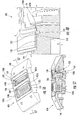


Classifications
-
- B—PERFORMING OPERATIONS; TRANSPORTING
- B41—PRINTING; LINING MACHINES; TYPEWRITERS; STAMPS
- B41J—TYPEWRITERS; SELECTIVE PRINTING MECHANISMS, i.e. MECHANISMS PRINTING OTHERWISE THAN FROM A FORME; CORRECTION OF TYPOGRAPHICAL ERRORS
- B41J2/00—Typewriters or selective printing mechanisms characterised by the printing or marking process for which they are designed
- B41J2/005—Typewriters or selective printing mechanisms characterised by the printing or marking process for which they are designed characterised by bringing liquid or particles selectively into contact with a printing material
- B41J2/01—Ink jet
- B41J2/135—Nozzles
- B41J2/16—Production of nozzles
- B41J2/1621—Manufacturing processes
- B41J2/1623—Manufacturing processes bonding and adhesion
-
- B—PERFORMING OPERATIONS; TRANSPORTING
- B41—PRINTING; LINING MACHINES; TYPEWRITERS; STAMPS
- B41J—TYPEWRITERS; SELECTIVE PRINTING MECHANISMS, i.e. MECHANISMS PRINTING OTHERWISE THAN FROM A FORME; CORRECTION OF TYPOGRAPHICAL ERRORS
- B41J2/00—Typewriters or selective printing mechanisms characterised by the printing or marking process for which they are designed
- B41J2/005—Typewriters or selective printing mechanisms characterised by the printing or marking process for which they are designed characterised by bringing liquid or particles selectively into contact with a printing material
- B41J2/01—Ink jet
- B41J2/135—Nozzles
- B41J2/14—Structure thereof only for on-demand ink jet heads
- B41J2/14016—Structure of bubble jet print heads
- B41J2/14024—Assembling head parts
-
- B—PERFORMING OPERATIONS; TRANSPORTING
- B41—PRINTING; LINING MACHINES; TYPEWRITERS; STAMPS
- B41J—TYPEWRITERS; SELECTIVE PRINTING MECHANISMS, i.e. MECHANISMS PRINTING OTHERWISE THAN FROM A FORME; CORRECTION OF TYPOGRAPHICAL ERRORS
- B41J2/00—Typewriters or selective printing mechanisms characterised by the printing or marking process for which they are designed
- B41J2/005—Typewriters or selective printing mechanisms characterised by the printing or marking process for which they are designed characterised by bringing liquid or particles selectively into contact with a printing material
- B41J2/01—Ink jet
- B41J2/135—Nozzles
- B41J2/14—Structure thereof only for on-demand ink jet heads
- B41J2/14201—Structure of print heads with piezoelectric elements
-
- B—PERFORMING OPERATIONS; TRANSPORTING
- B41—PRINTING; LINING MACHINES; TYPEWRITERS; STAMPS
- B41J—TYPEWRITERS; SELECTIVE PRINTING MECHANISMS, i.e. MECHANISMS PRINTING OTHERWISE THAN FROM A FORME; CORRECTION OF TYPOGRAPHICAL ERRORS
- B41J2/00—Typewriters or selective printing mechanisms characterised by the printing or marking process for which they are designed
- B41J2/005—Typewriters or selective printing mechanisms characterised by the printing or marking process for which they are designed characterised by bringing liquid or particles selectively into contact with a printing material
- B41J2/01—Ink jet
- B41J2/135—Nozzles
- B41J2/16—Production of nozzles
- B41J2/1601—Production of bubble jet print heads
-
- B—PERFORMING OPERATIONS; TRANSPORTING
- B41—PRINTING; LINING MACHINES; TYPEWRITERS; STAMPS
- B41J—TYPEWRITERS; SELECTIVE PRINTING MECHANISMS, i.e. MECHANISMS PRINTING OTHERWISE THAN FROM A FORME; CORRECTION OF TYPOGRAPHICAL ERRORS
- B41J2/00—Typewriters or selective printing mechanisms characterised by the printing or marking process for which they are designed
- B41J2/005—Typewriters or selective printing mechanisms characterised by the printing or marking process for which they are designed characterised by bringing liquid or particles selectively into contact with a printing material
- B41J2/01—Ink jet
- B41J2/135—Nozzles
- B41J2/16—Production of nozzles
- B41J2/1607—Production of print heads with piezoelectric elements
-
- B—PERFORMING OPERATIONS; TRANSPORTING
- B41—PRINTING; LINING MACHINES; TYPEWRITERS; STAMPS
- B41J—TYPEWRITERS; SELECTIVE PRINTING MECHANISMS, i.e. MECHANISMS PRINTING OTHERWISE THAN FROM A FORME; CORRECTION OF TYPOGRAPHICAL ERRORS
- B41J2/00—Typewriters or selective printing mechanisms characterised by the printing or marking process for which they are designed
- B41J2/005—Typewriters or selective printing mechanisms characterised by the printing or marking process for which they are designed characterised by bringing liquid or particles selectively into contact with a printing material
- B41J2/01—Ink jet
- B41J2/135—Nozzles
- B41J2/14—Structure thereof only for on-demand ink jet heads
- B41J2002/14362—Assembling elements of heads
Definitions
- a vacuum is created to draw fluid through nozzles of the print head. Leaks to atmosphere may impair such priming. Fluid communication between adjacent print heads may also lead to cross-contamination.
- EP 0 564 102 A2 describes a wide inkjet printhead.
- a liquid seal and adhesion between a nozzle member and a printhead wall are provided by cutting a slot in a bottom surface of the printhead wall, which is then filled with an adhesive.
- the slot circumscribes silicon dies when the nozzle member is mounted.
- Figures 1 and 2 schematically illustrate printing device 20 according to an example embodiment.
- Figure 1 further illustrates priming device 22 priming and servicing printing device 20.
- printing device 20 is configured to reduce leakage during priming to enhance effectiveness of priming and to reduce cross-contamination.
- printing device 20 includes fluid delivery system 26, print heads 28A, 28B (collectively referred to as print heads 28), flexible circuit 30, controller 32 and solidified adhesive paste layer 34.
- Fluid delivery system 26 comprises a mechanism configured to supply and deliver fluid, such as ink, to print heads 28.
- Fluid delivery system 26 includes a body 40, back pressure regulation mechanisms 44, filters 46 and standpipes 48.
- Body 40 comprises one or more structures configured to contain fluid. In one embodiment, body 40 may comprise a self-contained reservoir of fluid. In another embodiment, body 40 may receive fluid from a remote fluid supply or may circulate fluid to and across print heads 28.
- body 40 includes isolated internal chambers 41A and 41B (collectively referred to as chambers 41) for supplying distinct fluids to print heads 28A and 28B, respectively.
- chambers 41 for supplying distinct fluids to print heads 28A and 28B, respectively.
- a first color of ink may be supplied to print head 28A while a second distinct color of ink is applied to print head 28B.
- color includes black inks.
- body 40 may include greater or fewer of such isolated chambers.
- body 40 includes pockets 42A and 42B (collectively referred to as pockets 42). Pockets 42 comprise recesses or cavities formed in a lower side of body 40 configured to receive print heads 28. Due to clearances between pockets 42 and print heads 28, pockets 42 form gaps or moats 43 between print heads 28 and body 40. Although body 40 is illustrated as including two such pockets, in other embodiments, body 40 may include a greater or fewer of such pockets 42.
- Back pressure regulation mechanisms 44 comprise mechanisms configured to provide a controlled extent of back pressure so as to reduce the likelihood of fluid drooling through print heads 28.
- back pressure regulation mechanisms 44 include, but are not limited to, inflatable bags, foam or other capillary members.
- Filters 46 extend between mechanisms 44 and standpipes 48 to filter fluid prior to entering standpipes 48.
- Standpipes 48 comprise fluid passages including one or more slots for directing fluid to print heads 28.
- fluid delivery system 26 may include other mechanisms for delivering fluid to print heads 28 and may omit one or more of back pressure regulation mechanisms 44, filters 46 and standpipes 48.
- Print heads 28 comprise mechanisms to selectively eject fluid, such as ink, onto a print medium in response to control signal received from controller 32.
- print heads 28 may comprise thermoresistive drop-on-demand inkjet print heads.
- print heads 28 may comprise piezo resistive drop-on-demand inkjet print heads.
- Print heads 28 each include a series or array of openings or nozzles 52 configured to receive fluid from fluid delivery system 26. In the example illustrated, nozzles 52 of print heads 28 are in fluid communication with standpipes 48.
- print head 28A is in fluid communication with chamber 41A so as to selectively eject a first type of fluid.
- Print head 26B is in fluid communication with chamber 41B so as to selectively eject a second distinct type of fluid.
- printing device 20 may include a greater or fewer of such print heads 28.
- Flexible circuit 30 comprises a series or array of electrical circuits encased in a dielectric material, such as a polymeric encasement.
- the polymeric encasement comprises one or more polyamides.
- Flexible circuit extends from controller 32 to print heads 28.
- flexible circuit 30 includes openings 56A and 56B (collectively referred to as openings 56) such that flexible circuit 30 extends completely about or around pockets 42 and print heads 28 on all sides of print heads 28. Openings 56A and 56B are in substantial alignment with pocket 42A and with pocket 42B, as well as print head 28A and print head 28B, respectively.
- a portion of flexible circuit 30 slightly extends beneath or underlies a small portion of print heads 28, facilitating connection between flexible circuit 30 and print heads 28.
- Flexible circuit 30 bends and wraps about fluid delivery system 26, extends towards controller 32 and is coupled to or retained along a side of body 40 so as to not interfere with printing upon the print media.
- Flexible circuit 30 facilitates facilitate communication between print heads 28 and controller 32.
- flexible circuit 30 may have other configurations.
- flexible circuit 30 may openings 56 having different shapes and different relative locations.
- flexible circuit 30 may merely include a single opening 56 or may include greater than two openings 56.
- flexible circuit 30 may not extend completely about and on all sides of print heads 28.
- Controller 32 comprises one or more processing units coupled to print heads 28 by flexible circuit 30.
- processing unit shall mean a presently developed or future developed processing unit that executes sequences of instructions contained in a memory. Execution of the sequences of instructions causes the processing unit to perform steps such as generating control signals.
- the instructions may be loaded in a random access memory (RAM) for execution by the processing unit from a read only memory (ROM), a mass storage device, or some other persistent storage.
- RAM random access memory
- ROM read only memory
- mass storage device or some other persistent storage.
- hard wired circuitry may be used in place of or in combination with software instructions to implement the functions described.
- controller 32 may be embodied as part of one or more application-specific integrated circuits (ASICs).
- ASICs application-specific integrated circuits
- Controller 32 generates control signals which are transmitted by flexible circuit 30 to print heads 28.
- the control signals cause print heads 28 to selectively eject fluid through selected nozzles 52 in a controlled fashion.
- Solidified adhesive paste layer 34 comprises a layer or bead of solidified adhesive paste sandwiched between flexible circuit 30 and a lower surface or face 58 of body 40 at least partially about a perimeter of one or both of print heads 28.
- Solidified adhesive paste layer 34 has sufficiently low viscosity, prior to curing or solidification, such that the adhesive paste may flow into or wet gaps or voids in surface 58 as well as along the exterior of flexible circuit 30.
- layer 34 also accommodates surface irregularities or non-flatness associated with surface 58.
- the adhesive paste of layer 34 forms a hermetic seal between surface 58 and the opposing portion of flexible circuit 30.
- the seal formed by layer 34 between surface 58 of body 40 and flexible circuit 30 inhibits airflow or fluid flow between flexible circuit 30 and body 40. Consequently, priming is enhanced and cross-contamination of different fluids between print heads 28 is reduced.
- the adhesive paste material of layer 34 has a sufficiently low viscosity so as to readily flow into the gaps or voids a long surface 58 and along flexible circuit 30.
- the adhesive paste material has a viscosity at room temperature of less than or equal to about 200,000 centipoise (cp).
- the adhesive paste material a layer 34 comprises an epoxy paste.
- adhesive paste layer 34 comprises a 1 part epoxy paste (does not need mixing, but utilizes a curing process step).
- adhesive paste layer 34 comprises Bisphenol A thermosetting epoxy. In other embodiments, other types of adhesive pastes may be used..
- Adhesive paste layer 34 may be formed between flexible circuit 30 and surface 58 of body 40 in various manners. In one embodiment, adhesive paste material of layer 34 may be initially deposited upon flexible circuit 30, wherein flexible circuit 30 is then pressed against surface 58, bringing layer 34 into contact with surface 58. In another embodiment, adhesive paste material of layer 34 may be initially deposited upon surface 58, wherein flexible circuit 30 is pressed into contact with the adhesive paste material of layer 34 on surface 58.
- the adhesive paste material of layer 34 may be applied on one or both of flexible circuit 30 and surface 58 by various techniques including, but not limited to, robot needle dispensing, showerhead dispensing, manual needle dispensing, silk screening, or patterned preforms. With patterned preforms, the adhesive paste material may be in a non-paste state upon both sides of the preform, wherein the preform is treated, such as with the application of heat, so as to cause the adhesive paste material on the preform or backing to change to a paste state. Once in the paste state, the adhesive paste material on the preform may be pressed into contact with either surface 58 or flexible circuit 30 prior to being joined to the other of surface 58 or flexible circuit 30.
- solidified adhesive paste layer 34 extends at least partially about a perimeter of each of print heads 28.
- layer 34 continuously extends about both of print heads 28, collectively, while being sandwiched between surface 58 and circuit 30. As a result, layer 34 forms a continuous seal between circuit 30 and surface 58 about both of print heads 28.
- solidified adhesive paste layer 34 also continuously extends between print heads 28 while being sandwiched between surface 58 and circuit 30.
- Layer 34 also forms a continuous uninterrupted wall between print heads 28 to isolate print heads 28A and 28B from one another. As a result, layer 34 also inhibits the flow of fluid, such as ink, between circuit 30 and surface 58 from one of print heads 28 to another of print heads 28 to reduce or eliminate cross-contamination during priming.
- Figure 1 schematically illustrates priming using priming device 22.
- Priming device 22 includes cap 62, sealing members 64 and pump 66.
- Cap 62 comprises structure forming basins 68.
- Basins 68 provide volumes configured to be positioned opposite to print heads 28 so as to receive fluid drawn through nozzles 52 during priming of nozzles 52.
- Sealing members 64 comprise structures configured to seal against printing device 20.
- sealing members 64 seal against an underside of flexible circuit 30 or seal against those portions of surface 58 not covered by circuit 30 to prevent fluid flow between members 64 and flexible circuit 30 or to prevent fluid flow between members 64 and surface 58 during priming.
- sealing members 64 comprises elastomeric or compressible rings or gaskets of material configured to deform or compress when forming a seal against circuit 30 or portions of surface 58.
- Pump 66 comprises a fluid pump include communication with basins 68. Pump 66 is configured to draw or pump air from basins 68 so as to create a vacuum in basins 68 against print heads 28. In one embodiment, pump 66 may comprise a peristaltic pump. In other embodiments, pump 66 may have other configurations.
- the vacuum created in basins 68 by pump 66 draws fluid through nozzles 52 of print heads 28 into basins 68 to prime print heads 68.
- the withdrawn fluid is subsequently removed from basins 68 by pump 66.
- the vacuum created in basins 68 may also attempt to draw air between any gaps that may exist between flexible circuit 30 and surface 58 of body 40.
- solidified adhesive paste layer 34 fills any such avoids or irregularities and inhibits leakage of air into basins 68. As a result, priming performance is enhanced.
- the vacuums created within basins 68 may also tend to draw ejected fluid between surface 58 and flexible circuit 30 between print heads 28.
- solidified adhesive paste layer 34 fills any voids or cavities that may exist between circuit 30 and surface 58 between print heads 28 to prevent such fluid flow. As a result, layer 34 reduces or prevents cross-contamination of different types of fluid, such as different colors of ink.
- FIG. 3 illustrates printing device 120, a particular embodiment of printing device 20, with portions omitted for purposes of illustration.
- printing device 120 includes fluid delivery system 126, print heads 128A, 128B (collectively referred to as print heads 128), flexible circuit 130, controller 32 (shown in Figure 1 ) and solidified adhesive paste layer 134.
- Fluid delivery system 126, print heads 128 and flexible circuit 130 are substantially identical to fluid delivery system 26, print heads 28 and flexible circuit 30 shown and described with respect to Figures 1 and 2 .
- print heads 128 are illustrated without an overlying nozzle plate to better illustrate pockets 142A and 142B receiving and extending about print heads 128A and 128B, respectively.
- print heads 128A and 128B have slightly different configurations as compared to print heads 28A and 28B which are schematically shown in Figure 1 and 2 .
- solidified adhesive paste layer 134 comprises a layer or bead of solidified adhesive paste sandwiched between flexible circuit 130 and a lower surface or face 158 of body 140 about both of print heads 128.
- Solidified adhesive paste layer 34 has sufficiently low viscosity, prior to solidification, such that the adhesive paste may flow into or wet gaps or voids in surface 158 as well as along the exterior of flexible circuit 130.
- layer 134 also accommodates surface irregularities or non-flatness associated with surface 158. As a result, upon curing or other solidification, the adhesive paste of layer 134 forms a hermetic seal between surface 158 and the opposing portion of flexible circuit 130.
- the adhesive paste material of layer number 134 may only partially solidify, wherein the final layer 134 has a sufficiently high viscosity to maintain its integrity during priming.
- the seal formed by layer 134 between surface 158 of body 140 and flexible circuit 130 inhibits airflow or fluid flow between flexible circuit 130 and body 140. Consequently, priming is enhanced and cross-contamination of different fluids between print heads 128 is reduced.
- the adhesive paste material of layer 134 has a sufficiently low viscosity so as to readily flow into the gaps or voids along surface 158 and along flexible circuit 130.
- adhesive-paste material has a viscosity at room temperature of less than or equal to about 200,000 centipoise (cp).
- the adhesive paste material a layer 134 a 1 part epoxy paste (does not need mixing, but utilizes a curing process step).
- adhesive paste layer 134 comprises Bisphenol A thermosetting epoxy. In other embodiments, other types of adhesive pastes may be used..
- Adhesive paste layer 134 may be formed between flexible circuit 130 and surface 158 of body 140 in various manners. In one embodiment, adhesive paste material of layer 134 may be initially deposit upon flexible circuit 130, wherein flexible circuit 130 is then pressed against surface 158, bringing layer 134 into contact with surface 158. In another embodiment, adhesive paste material of layer 134 may be initially deposit upon surface 158, wherein flexible circuit 130 is pressed into contact with the adhesive paste material of layer 134 on surface 158.
- the adhesive paste material of layer 134 may be applied on one or both of flexible circuit 130 and surface 158 by various techniques including, but not limited to, robot needle dispensing, showerhead dispensing, manual needle dispensing, silk screening, or patterned preforms. With patterned preforms, the adhesive paste material may be in a non-paste state upon the preforms, wherein the preform is treated, such as with the application of heat, so as to cause the adhesive paste material on both sides of the preform or backing to change to a paste state. Once in the paste state, the adhesive paste material on the preform may be pressed into contact with either surface 158 or flexible circuit 130 prior to being joined to the other of surface 58 or flexible circuit 30.
- Figure 3 illustrates one example pattern 175 for layer 134.
- layer 134 continuously extends about both of print heads 128, collectively, while being sandwiched between surface 158 and circuit 130. As a result, layer 134 forms a continuous seal between circuit 130 and surface 158 about both of print heads 128.
- solidified adhesive paste layer '134 also continuously extends between print heads '128 while being sandwiched between surface ' 158 and circuit '130.
- Pattern 175 includes a loop 176 continuously extending about both print heads 128 and a segment 177 extending between printheads 128 and interconnecting opposite sides of look 176.
- Layer '134 forms a continuous wall between print heads 128 to isolate print heads 128A and 128B from one another. As a result, layer 134 also inhibits the flow of fluid, such as ink, between circuit 130 and surface 158 from one of print heads 128 to another of print heads 128 to reduce or eliminate cross-contamination during priming.
- Figure 3 further illustrates the position of priming device 22 (described above with respect to Figure 1 ) with respect to printing device 120 during priming to form a sealing zone.
- Figure 3 illustrates the relative positioning of sealing members 64 during priming.
- solidified adhesive paste layer 134 is formed between flexible circuit 130 and surface 158 of body 140 such that layer 134 is centrally located midway or equidistantly between the inner edges 178 of pockets 142. Layer 134 is also located midway between or equidistantly between the outer edges 180 of such pockets 142 and outboard edges 182 of flexible circuit 130.
- layer 134 is located midway between such edges, adhesive layer 134 is less likely to squeeze out into moats 143 and into pockets 142 where such adhesive paste may become deposited excessively close to the dies of print heads 128 so as to potentially interfere with wiping and impose strains upon the print head dies. Moreover, those portions of flexible circuit 130 overlying layer 134 are directly opposite to the nominal location or extent of sealing members 64 of priming device 22. As a result, sealing members 64 may better seal against the portion of the flexible circuit 130 rigidified by layer 134.
- adhesive layer 134 may be positioned or formed at other locations relative to edges 178, 180 and 182.
- portions of layer 134 may alternatively be formed proximate to or even along edges 182 or more proximate to and along edges 180. That portion of layer 134 extending between print heads 128 may alternatively extend or proximate to or even adjacent to edge 178 of the print head 128A or edge 178 of print head 128B. Even with such alternative embodiments, reduced leakage and reduced cross-contamination may be achieved.
- Figures 4-13 illustrate other alternative patterns for solidified adhesive paste layer 134.
- Figure 4 illustrates pattern 200 for solidified adhesive paste layer 134.
- Pattern 200 is similar to pattern 175 except that pattern 180 extends closer to edge 178 of print head 128A and additionally includes segments 202. Segments 202 provide additional adhesive areas for securing flexible circuit 130 to body 140. As a result, flexible circuit 130 is more securely retained along body 140.
- FIG. 5 illustrates pattern 205 for solidified adhesive paste layer 134.
- adhesive paste layer 134 comprises two continuous uninterrupted loops 207A, 207B continuously extending about an entire perimeter of each of print heads 128A and 128B, respectively.
- loops 207 are illustrated as being relatively close to print heads 128, in other embodiments, loops 207 may be more greatly spaced from edges of print heads 128 and their associated pockets 142.
- two walls 208 are provided between print heads 128, adding isolation between print heads 128 to reduce cross-contamination.
- Figure 6 illustrates pattern 210 of solidified adhesive paste layer 134.
- Pattern 210 is similar to pattern 205 except that pattern 210 additionally includes segments 212. Segments 212 provide enhanced securement of flexible circuit 130 (shown in Figure 3 ) relative to surface 158.
- Pattern 215 is similar to pattern 175 except that pattern 215 comprises a single loop 217 extending continuously and entirely about both print heads 128 without extending between print heads 128. Pattern 215 provides a lesser degree of isolation between print heads 128, but may be easier to apply and may be beneficial in embodiments where print heads 128 are extremely close to one another.
- Figure 8 illustrates pattern 220 of solidified adhesive paste layer 134.
- Pattern 220 is similar to pattern 215 except that pattern 220 additionally includes segments 222. Segments 222 provide enhanced securement of flexible circuit 130 (shown in Figure 3 ) relative to surface 158.
- Figures 9-12 illustrate various other patterns of adhesive paste layer 134, wherein layer 134 does not completely surround one or both of print heads 128, but alternatively extends along one or more sides of print heads 128.
- Figure 9 illustrates pattern 225 in which layer 34 comprises a single segment or line 227 extending across the shorter side of print heads 128.
- Figure 10 illustrates pattern 230.
- Pattern 230 is similar to pattern 225 except that pattern 230 includes an additional line 232 on an opposite side of print heads 128. Patterns 225 and 230 may reduce leakage along particular sides of print heads 128 and may provide enhanced securement of flexible circuit 130 (shown in Figure 3 ) as compared to a printing device 120 omitting layer 134.
- Figure 11 illustrates pattern 235 of solidified adhesive paste layer 134.
- Pattern 235 includes a pair of opposing segments or lines 237 extending on the longer sides of print heads 128 along opposite side to apprentice 128. Lines 237 may reduce leakage along particular sides of print heads 128 and may provide enhanced securement of flexible circuit 130 (shown in Figure 3 ) as compared to a printing device 120 omitting layer 134.
- Figure 12 illustrates pattern 240 of solidified adhesive paste layer 134.
- Pattern 240 is similar to pattern 235 except that pattern 240 additionally includes segment or line 242.
- Line 242 extends between print heads 128. Line 242 provides additional isolation between print heads 128 to reduce likelihood of cross contamination.
- Figures 13-15 illustrate printing device 320, another embodiment of printing devices 20 and 120.
- Printing device 320 is similar to printing device 120 with pattern 175 of solidified adhesive paste layer 134 except that surface 158 of body 140 of fluid delivery system 126 includes a depression, groove, channel or trench 323 extending into surface 158.
- trench 323 has the same pattern as that of solidified adhesive paste layer 134. In the example illustrated, trench 323 continuously extends about print heads 128 and between print heads 128. In other embodiments wherein layer 134 has other patterns, such as those shown in Figures 4-12 , trench 323 may also have corresponding patterns.
- trench 323 receives solidified adhesive paste layer 134.
- Trench 323 limits or contains extent to which the adhesive paste material of layer 134 may migrate prior to partial or complete solidification.
- Trench 323 further provides flexible circuit 130 with a greater degree of flatness or levelness.
- the material of adhesive paste layer 134 (prior to solidification)- is directly deposited into trench 323 to a height at, just above or proximate to surface 158 so as to contact and seal against flexible circuit 130.
- trench 323 enables a greater volume of the adhesive paste material layer 34 to be applied without a corresponding unevenness of flexible circuit 130 being created.
- Flexible circuit 130 may have a greater degree of parallelism with surface 158.
- trench 323 may enhance subsequent sealing against flexible circuit 130 during priming and may permit printing device 320 to be positioned closer to media during printing.
- trench 323 has a width of between about 0.25mm and about 2mm (nominally about 0.5mm) and a depth of between about 0.1mm and about 2mm (nominally about 0.25mm). In other embodiments, trench 323 may have other widths or depths depending upon the desired amount of adhesive paste material that is to be used to form layer 134.
- FIG 16-18 illustrate printing device 420 another embodiment of printing devices 20 and 120.
- Printing device 420 is similar to printing device 320 except that solidified adhesive paste layer 134 and trenches 323 each have pattern 205 as shown and described above with respect to Figure 5 .
- trenches 323 comprise two distinct loops 427A and 427B (collectively referred to as loops 427). Loop 327A continuously extends about print head 128A. Loop 427 continuously extends about print head 128B.
- loops 427 directly receive adhesive paste material of layer 134.
- Trenches 323 serve to contain the adhesive paste material as it cures or solidifies. As noted above, trench 323 further enhances flatness of flexible circuit 130. Because trenches 323 and layer 134 form two independent isolation walls 430 between print heads 128, enhanced isolation of print heads 128 is provided which may reduce cross-contamination during priming.
- Figures 19-21 illustrate printing device 520, another embodiment of printing devices 20 and 120.
- Printing device 520 is similar to printing device 320 with solidified adhesive paste layer 134 having pattern 175 except that printing device 520 additionally includes impressions, grooves, channels or trenches 523.
- Trenches 523 extend into surface 158 on one or both sides of layer 134. Trenches 523 serve as overflow channels or gutters by receiving excess adhesive paste material of layer 134 as flexible circuit 130 and surface 158 are being pressed against one another prior to curing or solidification of the adhesive paste material of layer 134.
- the material of adhesive paste layer 134 (prior to solidification) is deposited directly upon surface 158 near trenches 523.
- trenches 523 serve to contain the extent to which the adhesive paste material may migrate along surface 158 prior to solidification. Trenches 523 further receive excess adhesive paste material, reducing unevenness of flexible circuit 130 and enhancing the degree of flatness of flexible circuit 130 to potentially improve the ability of priming device 22 (shown in Figure 1 ) to form a seal against flexible circuit 130.
- trenches 532 form two distinct loops 537A and 537B (collectively referred to as loops 537). Those portions of loops 537 between print heads 128 form an intermediate plateau, rib or landing 541. In the example illustrated, the portion of layer 134 extending between print heads 128 is a largely centered on landing 541. As a result, layer 134 between print heads 128 is contained in both directions by trenches 523. Thus, layer 134 may be provided in closer proximity to one or both print heads 128 with a reduced likelihood of layer 134 interfering with or affecting the performance of print heads 128. This allows print is 128 to also be positioned closer to one another for a more compact design. At the same time, layer 134 continues to provide enhanced isolation between print heads 128 to reduce the likelihood of cross-contamination during priming.
- those portions of loops 537 of trenches 523 not between print heads 128 extend on one side of layer 134 to the outside of layer 134.
- layer 134 may be provided distant from pockets 142 and print heads 128 closer to an outer edge of flexible circuit 130 with a reduced likelihood of the adhesive paste material of layer 134 migrating or being squeezed too far to the outside. Since layer 134 is distant pockets 142 and print heads 128, any inward migration of the adhesive paste material of layer 34 has little if any harmful results.
- trenches 523 have a width of between about 0.25mm and about 2mm (nominally about 0.5mm) and a depth of between about 0.25mm and about 2mm (nominally about 0.5mm). In other embodiments, trenches 523 may have other widths or depths depending upon the anticipated extent overflow of adhesive paste material of layer 134 and available area of surface 158. Moreover, in some embodiments, selected portions of trenches 523 may have varying dimensions. For example, portions of trenches 523 between print heads 128 may have a reduced width and increased depth as compared to other portions of trenches 523 not between print heads 128, permitting print heads 128 to be closer to one another.
- trenches 523 may have other patterns and configurations.
- trenches 523 may alternatively extend on the inside edge of layer 134 between layer 134 and moats 143 so as to prevent inward migration of the adhesive paste material of layer 134, prior to solidification or curing, towards print heads 128.
- trenches 523 are illustrated as being continuous, in other embodiments, trenches 523 may be intermittently located along one or both edges of layer 134 while still providing some degree of containment for the adhesive paste material of layer 134.
- Figures 22-24 illustrate printing device 620, another embodiment of printing devices 20 and 120.
- Printing device 620 is similar to printing device 320 with solidified adhesive paste layer 134 having pattern 175 except that printing device 520 additionally includes impressions, grooves, channels or trenches 623.
- Trenches 623 extend into surface 158 on both sides of layer 134. Trenches 623 receive excess adhesive paste material of layer 134 as flexible circuit 130 and surface 158 are being pressed against one another prior to curing or solidification of the adhesive paste material of layer 134.
- trenches 623 serve to contain the extent to which the adhesive paste material may migrate along surface 158 prior to solidification. Trenches 623 further receive excess adhesive paste material, reducing unevenness of flexible circuit 130 and enhancing the degree of flatness of flexible circuit 130 to potentially improve the ability of priming device 22 (shown in Figure 1 ) to form a seal against flexible circuit 130.
- trenches 623 form two distinct interior loops 637A and 637B (collectively referred to as loops 637) extending about print heads 128A and 128B, respectively.
- Trenches 623 further include a continuous outer loop 639 that extends alongside and substantially parallel to a collective outer perimeter of loops 637.
- Intermediate loops 637 are spaced from one another between print heads 128 to form an intermediate plateau, rib or landing 641.
- Outer loop 639 is spaced from inner loops 637 to form an intermediate plateau, rib or landing 643.
- layer 134 is largely centered on landings 641 and 643. As a result, layer 134 between print heads 128 is contained in both directions by trenches 623.
- layer 134 may be provided in closer proximity to one or both print heads 128 between print heads 128 with a reduced likelihood of layer 134 interfering with or affecting the performance of print heads 128. This allows print heads 128 to also be positioned closer to one another for a more compact design. At the same time, layer 134 continues to provide enhanced isolation between print heads 128 to reduce the likelihood of cross-contamination during priming. In addition, layer 134 may also be located closer to an outboard edge of flexible circuit 130 for enhanced sealing.
- trenches 623 of loops 637 have a width of between about 0.25mm and about 2mm (nominally about 0.5mm) and a depth of between about 0.25mm and about 2mm (nominally about 0.5mm).
- Trench 623 of loop 639 has a width of between about 0.25mm and about 2mm (nominally about 0.5mm) and a depth of between about 0.25mm and about 2mm (nominally about 0.5mm).
- trenches 623 may have other widths or depths depending upon the anticipated extent overflow of adhesive paste material of layer numeral 134 and available area of surface 158.
- selected portions of trenches 623 may have varying dimensions. For example, portions of trenches 623 between print heads 128 may have a reduced width and increased depth as compared to other portions of trenches 623 not between print heads 128, permitting print heads 128 to be closer to one another.
- Embodiments relate to an apparatus comprising a flexible circuit 30 having an opening 56 configured to be aligned with a print head 28, and a bead of adhesive material 134 capable of attaining a paste state upon the flexible circuit 30 and surrounding the opening 56.
- Embodiments relate to a method comprising providing a print head 28 having nozzle openings 52, coupling the print head 28 to a fluid delivery system 26, providing a flexible circuit 30, forming a layer 34, 134 of adhesive paste on one of the flexible circuit 30 and the fluid delivery system 26, and positioning the layer 34, 134 of adhesive paste against the other of the flexible circuit 30 and the fluid delivery system 26 at least partially about a perimeter of the print head 28, wherein the layer 34, 134 of adhesive paste is formed by treating a pre-form from a non-paste state to a paste state.
- Embodiments relate to a method comprising providing a print head 28 having nozzle openings 52, coupling the print head 28 to a fluid delivery system 26, providing a flexible circuit 30, forming a layer 34, 134 of adhesive paste on one of the flexible circuit 30 and the fluid delivery system 26, and positioning the layer 34, 134 of adhesive paste against the other of the flexible circuit 30 and the fluid delivery system 26 at least partially about a perimeter of the print head 28, wherein the layer 34, 134 of adhesive paste is formed by ejecting a bead of viscous adhesive paste on one of the flexible circuit 30 and the fluid delivery system 26.
- Embodiments relate to a method comprising providing a print head 28 having nozzle openings 52, coupling the print head 28 to a fluid delivery system 26, providing a flexible circuit 30, forming a layer 34, 134 of adhesive paste on one of the flexible circuit 30 and the fluid delivery system 26, and positioning the layer 34, 134 of adhesive paste against the other of the flexible circuit 30 and the fluid delivery system 26 at least partially about a perimeter of the print head 28, wherein the layer 34, 134 of adhesive paste has a viscosity of less than or equal to about 200,000 centipoise during the forming of the layer 34, 134 on one of the flexible circuit 30 and the fluid delivery system 26.
- Embodiments relate to a method comprising providing a print head 28 having nozzle openings 52, coupling the print head 28 to a fluid delivery system 26, providing a flexible circuit 30, forming a layer 34, 134 of adhesive paste on one of the flexible circuit 30 and the fluid delivery system 26, and positioning the layer 34, 134 of adhesive paste against the other of the flexible circuit 30 and the fluid delivery system 26 at least partially about a perimeter of the print head 28, wherein the fluid delivery system 26 includes a trench 523, 623 spaced from the print head 28 and wherein positioning the layer 134 of adhesive paste against the other of the flexible circuit 30 in the fluid deli system 26 squeezes some of the adhesive paste into the trench 523, 623.
Landscapes
- Engineering & Computer Science (AREA)
- Manufacturing & Machinery (AREA)
- Particle Formation And Scattering Control In Inkjet Printers (AREA)
Description
- During print head priming, a vacuum is created to draw fluid through nozzles of the print head. Leaks to atmosphere may impair such priming. Fluid communication between adjacent print heads may also lead to cross-contamination.
-
EP 0 564 102 A2 -
-
Figure 1 is a sectional view of schematically illustrating priming of a printing device according to an example embodiment. -
Figure 2 is a sectional view of the printing device ofFigure 1 taken along line 2-2 according to an example embodiment. -
Figure 3 is a bottom plan view of another embodiment of the printing device ofFigure 1 illustrating relative positioning of a sealing zone during priming according to an example embodiment. -
Figures 4-12 are bottom plan view the illustrating various patterns for a solidified adhesive paste layer of the printing device ofFigure 3 according to an example embodiment. -
Figure 13 is a top perspective view of another embodiment of the printing device ofFigure 3 according to an example embodiment. -
Figure 14 is a sectional view of the printing device ofFigure 13 taken along line 14-14 according to an example embodiment. -
Figure 15 is an enlarged view of a portion of the printing device ofFigure 14 according to an example embodiment. -
Figure 16 is a top perspective view of another embodiment of the printing device ofFigure 3 according to an example embodiment. -
Figure 17 is a sectional view of the printing device ofFigure 16 taken along line 17-17 according to an example embodiment. -
Figure 18 is an enlarged view of a portion of the printing device ofFigure 17 according to an example embodiment. -
Figure 19 is a top perspective view of another embodiment of the printing device ofFigure 3 according to an example embodiment. -
Figure 20 is a sectional view of the printing device ofFigure 19 taken along line 20-20 according to an example embodiment. -
Figure 21 is an enlarged view of a portion of the printing device ofFigure 20 according to an example embodiment. -
Figure 22 is a top perspective view of another embodiment of the printing device ofFigure 3 according to an example embodiment. -
Figure 23 is a sectional view of the printing device ofFigure 22 taken along line 22-22 according to an example embodiment. -
Figure 24 is an enlarged view of a portion of the printing device ofFigure 22 according to an example embodiment. -
Figures 1 and 2 schematically illustrateprinting device 20 according to an example embodiment.Figure 1 further illustratespriming device 22 priming andservicing printing device 20. As will be described hereafter,printing device 20 is configured to reduce leakage during priming to enhance effectiveness of priming and to reduce cross-contamination. - As shown by
Figure 1 ,printing device 20 includesfluid delivery system 26,print heads flexible circuit 30,controller 32 and solidifiedadhesive paste layer 34.Fluid delivery system 26 comprises a mechanism configured to supply and deliver fluid, such as ink, to print heads 28.Fluid delivery system 26 includes abody 40, backpressure regulation mechanisms 44,filters 46 andstandpipes 48.Body 40 comprises one or more structures configured to contain fluid. In one embodiment,body 40 may comprise a self-contained reservoir of fluid. In another embodiment,body 40 may receive fluid from a remote fluid supply or may circulate fluid to and across print heads 28. - In the embodiment illustrated,
body 40 includes isolatedinternal chambers print heads head 28A while a second distinct color of ink is applied to printhead 28B. For purposes of this disclosure, with reference to inks, the term "color" includes black inks. In other embodiment,body 40 may include greater or fewer of such isolated chambers. - In the example illustrated in
Figure 1 ,body 40 includespockets body 40 configured to receive print heads 28. Due to clearances between pockets 42 and print heads 28, pockets 42 form gaps ormoats 43 between print heads 28 andbody 40. Althoughbody 40 is illustrated as including two such pockets, in other embodiments,body 40 may include a greater or fewer of such pockets 42. - Back pressure regulation mechanisms 44 (schematically shown) comprise mechanisms configured to provide a controlled extent of back pressure so as to reduce the likelihood of fluid drooling through print heads 28. Examples of back
pressure regulation mechanisms 44 include, but are not limited to, inflatable bags, foam or other capillary members.Filters 46 extend betweenmechanisms 44 andstandpipes 48 to filter fluid prior to enteringstandpipes 48.Standpipes 48 comprise fluid passages including one or more slots for directing fluid to print heads 28. In other embodiments,fluid delivery system 26 may include other mechanisms for delivering fluid to print heads 28 and may omit one or more of backpressure regulation mechanisms 44,filters 46 andstandpipes 48. - Print heads 28 comprise mechanisms to selectively eject fluid, such as ink, onto a print medium in response to control signal received from
controller 32. In one embodiment, print heads 28 may comprise thermoresistive drop-on-demand inkjet print heads. In another embodiment, print heads 28 may comprise piezo resistive drop-on-demand inkjet print heads. Print heads 28 each include a series or array of openings ornozzles 52 configured to receive fluid fromfluid delivery system 26. In the example illustrated,nozzles 52 of print heads 28 are in fluid communication withstandpipes 48. - In the particular example illustrated,
print head 28A is in fluid communication withchamber 41A so as to selectively eject a first type of fluid. Print head 26B is in fluid communication withchamber 41B so as to selectively eject a second distinct type of fluid. In other embodiments,printing device 20 may include a greater or fewer of such print heads 28. -
Flexible circuit 30 comprises a series or array of electrical circuits encased in a dielectric material, such as a polymeric encasement. In one embodiment, the polymeric encasement comprises one or more polyamides. Flexible circuit extends fromcontroller 32 to print heads 28. As shown byFigure 2 ,flexible circuit 30 includesopenings flexible circuit 30 extends completely about or around pockets 42 and print heads 28 on all sides of print heads 28.Openings pocket 42A and withpocket 42B, as well asprint head 28A andprint head 28B, respectively. - As shown by
Figure 2 , in the example illustrated, a portion offlexible circuit 30 slightly extends beneath or underlies a small portion of print heads 28, facilitating connection betweenflexible circuit 30 and print heads 28.Flexible circuit 30 bends and wraps aboutfluid delivery system 26, extends towardscontroller 32 and is coupled to or retained along a side ofbody 40 so as to not interfere with printing upon the print media.Flexible circuit 30 facilitates facilitate communication between print heads 28 andcontroller 32. - In other embodiments,
flexible circuit 30 may have other configurations. For example, in other embodiments,flexible circuit 30 may openings 56 having different shapes and different relative locations. In other embodiments,flexible circuit 30 may merely include asingle opening 56 or may include greater than twoopenings 56. In other embodiments,flexible circuit 30 may not extend completely about and on all sides of print heads 28. -
Controller 32 comprises one or more processing units coupled to print heads 28 byflexible circuit 30. For purposes of this application, the term "processing unit" shall mean a presently developed or future developed processing unit that executes sequences of instructions contained in a memory. Execution of the sequences of instructions causes the processing unit to perform steps such as generating control signals. The instructions may be loaded in a random access memory (RAM) for execution by the processing unit from a read only memory (ROM), a mass storage device, or some other persistent storage. In other embodiments, hard wired circuitry may be used in place of or in combination with software instructions to implement the functions described. For example,controller 32 may be embodied as part of one or more application-specific integrated circuits (ASICs). Unless otherwise specifically noted, the controller is not limited to any specific combination of hardware circuitry and software, nor to any particular source for the instructions executed by the processing unit.Controller 32 generates control signals which are transmitted byflexible circuit 30 to print heads 28. The control signals cause print heads 28 to selectively eject fluid through selectednozzles 52 in a controlled fashion. - Solidified
adhesive paste layer 34 comprises a layer or bead of solidified adhesive paste sandwiched betweenflexible circuit 30 and a lower surface or face 58 ofbody 40 at least partially about a perimeter of one or both of print heads 28. Solidifiedadhesive paste layer 34 has sufficiently low viscosity, prior to curing or solidification, such that the adhesive paste may flow into or wet gaps or voids insurface 58 as well as along the exterior offlexible circuit 30. In addition,layer 34 also accommodates surface irregularities or non-flatness associated withsurface 58. As a result, upon curing or other solidification, the adhesive paste oflayer 34 forms a hermetic seal betweensurface 58 and the opposing portion offlexible circuit 30. The seal formed bylayer 34 betweensurface 58 ofbody 40 andflexible circuit 30 inhibits airflow or fluid flow betweenflexible circuit 30 andbody 40. Consequently, priming is enhanced and cross-contamination of different fluids between print heads 28 is reduced. - In the example illustrated, the adhesive paste material of
layer 34 has a sufficiently low viscosity so as to readily flow into the gaps or voids along surface 58 and alongflexible circuit 30. In one embodiment, the adhesive paste material has a viscosity at room temperature of less than or equal to about 200,000 centipoise (cp). In one embodiment, the adhesive paste material alayer 34 comprises an epoxy paste. In one embodiment,adhesive paste layer 34 comprises a 1 part epoxy paste (does not need mixing, but utilizes a curing process step). In one embodiment,adhesive paste layer 34 comprises Bisphenol A thermosetting epoxy. In other embodiments, other types of adhesive pastes may be used.. -
Adhesive paste layer 34 may be formed betweenflexible circuit 30 andsurface 58 ofbody 40 in various manners. In one embodiment, adhesive paste material oflayer 34 may be initially deposited uponflexible circuit 30, whereinflexible circuit 30 is then pressed againstsurface 58, bringinglayer 34 into contact withsurface 58. In another embodiment, adhesive paste material oflayer 34 may be initially deposited uponsurface 58, whereinflexible circuit 30 is pressed into contact with the adhesive paste material oflayer 34 onsurface 58. - The adhesive paste material of
layer 34 may be applied on one or both offlexible circuit 30 andsurface 58 by various techniques including, but not limited to, robot needle dispensing, showerhead dispensing, manual needle dispensing, silk screening, or patterned preforms. With patterned preforms, the adhesive paste material may be in a non-paste state upon both sides of the preform, wherein the preform is treated, such as with the application of heat, so as to cause the adhesive paste material on the preform or backing to change to a paste state. Once in the paste state, the adhesive paste material on the preform may be pressed into contact with eithersurface 58 orflexible circuit 30 prior to being joined to the other ofsurface 58 orflexible circuit 30. - As shown by
Figure 2 , solidifiedadhesive paste layer 34 extends at least partially about a perimeter of each of print heads 28. In the example illustrated,layer 34 continuously extends about both of print heads 28, collectively, while being sandwiched betweensurface 58 andcircuit 30. As a result,layer 34 forms a continuous seal betweencircuit 30 andsurface 58 about both of print heads 28. - As further shown by
Figure 2 , solidifiedadhesive paste layer 34 also continuously extends between print heads 28 while being sandwiched betweensurface 58 andcircuit 30.Layer 34 also forms a continuous uninterrupted wall between print heads 28 to isolateprint heads layer 34 also inhibits the flow of fluid, such as ink, betweencircuit 30 andsurface 58 from one of print heads 28 to another of print heads 28 to reduce or eliminate cross-contamination during priming. -
Figure 1 schematically illustrates priming usingpriming device 22. Primingdevice 22 includescap 62, sealingmembers 64 andpump 66.Cap 62 comprisesstructure forming basins 68.Basins 68 provide volumes configured to be positioned opposite to print heads 28 so as to receive fluid drawn throughnozzles 52 during priming ofnozzles 52. -
Sealing members 64 comprise structures configured to seal againstprinting device 20. In the example illustrated, sealingmembers 64 seal against an underside offlexible circuit 30 or seal against those portions ofsurface 58 not covered bycircuit 30 to prevent fluid flow betweenmembers 64 andflexible circuit 30 or to prevent fluid flow betweenmembers 64 andsurface 58 during priming. In one embodiment, sealingmembers 64 comprises elastomeric or compressible rings or gaskets of material configured to deform or compress when forming a seal againstcircuit 30 or portions ofsurface 58. -
Pump 66 comprises a fluid pump include communication withbasins 68.Pump 66 is configured to draw or pump air frombasins 68 so as to create a vacuum inbasins 68 against print heads 28. In one embodiment, pump 66 may comprise a peristaltic pump. In other embodiments, pump 66 may have other configurations. - As schematically represented by
arrows 70, the vacuum created inbasins 68 bypump 66 draws fluid throughnozzles 52 of print heads 28 intobasins 68 to prime print heads 68. The withdrawn fluid is subsequently removed frombasins 68 bypump 66. As schematically represented by crossed outarrows 72, the vacuum created inbasins 68 may also attempt to draw air between any gaps that may exist betweenflexible circuit 30 andsurface 58 ofbody 40. However, solidifiedadhesive paste layer 34 fills any such avoids or irregularities and inhibits leakage of air intobasins 68. As a result, priming performance is enhanced. - At the same time, as schematically represented by crossed out
arrows 74, the vacuums created withinbasins 68 may also tend to draw ejected fluid betweensurface 58 andflexible circuit 30 between print heads 28. However, solidifiedadhesive paste layer 34 fills any voids or cavities that may exist betweencircuit 30 andsurface 58 between print heads 28 to prevent such fluid flow. As a result,layer 34 reduces or prevents cross-contamination of different types of fluid, such as different colors of ink. -
Figure 3 illustratesprinting device 120, a particular embodiment ofprinting device 20, with portions omitted for purposes of illustration. As shown byFigure 3 ,printing device 120 includesfluid delivery system 126,print heads flexible circuit 130, controller 32 (shown inFigure 1 ) and solidifiedadhesive paste layer 134.Fluid delivery system 126, print heads 128 andflexible circuit 130 are substantially identical tofluid delivery system 26, print heads 28 andflexible circuit 30 shown and described with respect toFigures 1 and 2 . For purposes of illustration, print heads 128 are illustrated without an overlying nozzle plate to better illustratepockets print heads Figure 3 ,print heads print heads Figure 1 and 2 . - As further shown by
Figure 3 , solidifiedadhesive paste layer 134 comprises a layer or bead of solidified adhesive paste sandwiched betweenflexible circuit 130 and a lower surface or face 158 ofbody 140 about both of print heads 128. Solidifiedadhesive paste layer 34 has sufficiently low viscosity, prior to solidification, such that the adhesive paste may flow into or wet gaps or voids insurface 158 as well as along the exterior offlexible circuit 130. In addition,layer 134 also accommodates surface irregularities or non-flatness associated withsurface 158. As a result, upon curing or other solidification, the adhesive paste oflayer 134 forms a hermetic seal betweensurface 158 and the opposing portion offlexible circuit 130. In particular embodiments, the adhesive paste material oflayer number 134 may only partially solidify, wherein thefinal layer 134 has a sufficiently high viscosity to maintain its integrity during priming. The seal formed bylayer 134 betweensurface 158 ofbody 140 andflexible circuit 130 inhibits airflow or fluid flow betweenflexible circuit 130 andbody 140. Consequently, priming is enhanced and cross-contamination of different fluids between print heads 128 is reduced. - In the example illustrated, the adhesive paste material of
layer 134 has a sufficiently low viscosity so as to readily flow into the gaps or voids alongsurface 158 and alongflexible circuit 130. In one embodiment, adhesive-paste material has a viscosity at room temperature of less than or equal to about 200,000 centipoise (cp). In one embodiment, the adhesive paste material a layer 134 a 1 part epoxy paste (does not need mixing, but utilizes a curing process step). In one embodiment,adhesive paste layer 134 comprises Bisphenol A thermosetting epoxy. In other embodiments, other types of adhesive pastes may be used.. -
Adhesive paste layer 134 may be formed betweenflexible circuit 130 andsurface 158 ofbody 140 in various manners. In one embodiment, adhesive paste material oflayer 134 may be initially deposit uponflexible circuit 130, whereinflexible circuit 130 is then pressed againstsurface 158, bringinglayer 134 into contact withsurface 158. In another embodiment, adhesive paste material oflayer 134 may be initially deposit uponsurface 158, whereinflexible circuit 130 is pressed into contact with the adhesive paste material oflayer 134 onsurface 158. - The adhesive paste material of
layer 134 may be applied on one or both offlexible circuit 130 andsurface 158 by various techniques including, but not limited to, robot needle dispensing, showerhead dispensing, manual needle dispensing, silk screening, or patterned preforms. With patterned preforms, the adhesive paste material may be in a non-paste state upon the preforms, wherein the preform is treated, such as with the application of heat, so as to cause the adhesive paste material on both sides of the preform or backing to change to a paste state. Once in the paste state, the adhesive paste material on the preform may be pressed into contact with eithersurface 158 orflexible circuit 130 prior to being joined to the other ofsurface 58 orflexible circuit 30. -
Figure 3 illustrates oneexample pattern 175 forlayer 134. Withpattern 175,layer 134 continuously extends about both of print heads 128, collectively, while being sandwiched betweensurface 158 andcircuit 130. As a result,layer 134 forms a continuous seal betweencircuit 130 andsurface 158 about both of print heads 128. - With
pattern 175, solidified adhesive paste layer '134 also continuously extends between print heads '128 while being sandwiched between surface ' 158 and circuit '130.Pattern 175 includes aloop 176 continuously extending about both print heads 128 and asegment 177 extending between printheads 128 and interconnecting opposite sides oflook 176. Layer '134 forms a continuous wall between print heads 128 to isolateprint heads layer 134 also inhibits the flow of fluid, such as ink, betweencircuit 130 andsurface 158 from one of print heads 128 to another of print heads 128 to reduce or eliminate cross-contamination during priming. -
Figure 3 further illustrates the position of priming device 22 (described above with respect toFigure 1 ) with respect toprinting device 120 during priming to form a sealing zone. In particular,Figure 3 illustrates the relative positioning of sealingmembers 64 during priming. As shown byFigure 3 , solidifiedadhesive paste layer 134 is formed betweenflexible circuit 130 andsurface 158 ofbody 140 such thatlayer 134 is centrally located midway or equidistantly between theinner edges 178 of pockets 142.Layer 134 is also located midway between or equidistantly between theouter edges 180 of such pockets 142 andoutboard edges 182 offlexible circuit 130. Becauselayer 134 is located midway between such edges,adhesive layer 134 is less likely to squeeze out intomoats 143 and into pockets 142 where such adhesive paste may become deposited excessively close to the dies of print heads 128 so as to potentially interfere with wiping and impose strains upon the print head dies. Moreover, those portions offlexible circuit 130overlying layer 134 are directly opposite to the nominal location or extent of sealingmembers 64 of primingdevice 22. As a result, sealingmembers 64 may better seal against the portion of theflexible circuit 130 rigidified bylayer 134. - In other embodiments,
adhesive layer 134 may be positioned or formed at other locations relative toedges layer 134 may alternatively be formed proximate to or even alongedges 182 or more proximate to and alongedges 180. That portion oflayer 134 extending between print heads 128 may alternatively extend or proximate to or even adjacent to edge 178 of theprint head 128A or edge 178 ofprint head 128B. Even with such alternative embodiments, reduced leakage and reduced cross-contamination may be achieved. -
Figures 4-13 illustrate other alternative patterns for solidifiedadhesive paste layer 134.Figure 4 illustratespattern 200 for solidifiedadhesive paste layer 134.Pattern 200 is similar topattern 175 except thatpattern 180 extends closer to edge 178 ofprint head 128A and additionally includessegments 202.Segments 202 provide additional adhesive areas for securingflexible circuit 130 tobody 140. As a result,flexible circuit 130 is more securely retained alongbody 140. -
Figure 5 illustratespattern 205 for solidifiedadhesive paste layer 134. As shown byFigure 5 , withpattern 205,adhesive paste layer 134 comprises two continuousuninterrupted loops print heads pattern 205, twowalls 208 are provided between print heads 128, adding isolation between print heads 128 to reduce cross-contamination. -
Figure 6 illustratespattern 210 of solidifiedadhesive paste layer 134.Pattern 210 is similar topattern 205 except thatpattern 210 additionally includessegments 212.Segments 212 provide enhanced securement of flexible circuit 130 (shown inFigure 3 ) relative to surface 158. -
Figure 7 illustratespattern 215 of solidifiedadhesive paste layer 134.Pattern 215 is similar topattern 175 except thatpattern 215 comprises asingle loop 217 extending continuously and entirely about both print heads 128 without extending between print heads 128.Pattern 215 provides a lesser degree of isolation between print heads 128, but may be easier to apply and may be beneficial in embodiments where print heads 128 are extremely close to one another. -
Figure 8 illustratespattern 220 of solidifiedadhesive paste layer 134.Pattern 220 is similar topattern 215 except thatpattern 220 additionally includessegments 222.Segments 222 provide enhanced securement of flexible circuit 130 (shown inFigure 3 ) relative to surface 158. -
Figures 9-12 illustrate various other patterns ofadhesive paste layer 134, whereinlayer 134 does not completely surround one or both of print heads 128, but alternatively extends along one or more sides of print heads 128.Figure 9 illustratespattern 225 in whichlayer 34 comprises a single segment orline 227 extending across the shorter side of print heads 128.Figure 10 illustratespattern 230.Pattern 230 is similar topattern 225 except thatpattern 230 includes anadditional line 232 on an opposite side of print heads 128.Patterns Figure 3 ) as compared to aprinting device 120omitting layer 134. -
Figure 11 illustratespattern 235 of solidifiedadhesive paste layer 134.Pattern 235 includes a pair of opposing segments orlines 237 extending on the longer sides of print heads 128 along opposite side to apprentice 128.Lines 237 may reduce leakage along particular sides of print heads 128 and may provide enhanced securement of flexible circuit 130 (shown inFigure 3 ) as compared to aprinting device 120omitting layer 134. -
Figure 12 illustratespattern 240 of solidifiedadhesive paste layer 134.Pattern 240 is similar topattern 235 except thatpattern 240 additionally includes segment or line 242. Line 242 extends between print heads 128. Line 242 provides additional isolation between print heads 128 to reduce likelihood of cross contamination. -
Figures 13-15 illustrateprinting device 320, another embodiment ofprinting devices Printing device 320 is similar toprinting device 120 withpattern 175 of solidifiedadhesive paste layer 134 except thatsurface 158 ofbody 140 offluid delivery system 126 includes a depression, groove, channel ortrench 323 extending intosurface 158. As shown byFigure 13 ,trench 323 has the same pattern as that of solidifiedadhesive paste layer 134. In the example illustrated,trench 323 continuously extends about print heads 128 and between print heads 128. In other embodiments whereinlayer 134 has other patterns, such as those shown inFigures 4-12 ,trench 323 may also have corresponding patterns. - As shown by
Figures 14 and 15 ,trench 323 receives solidifiedadhesive paste layer 134. Trench 323 limits or contains extent to which the adhesive paste material oflayer 134 may migrate prior to partial or complete solidification. Trench 323 further providesflexible circuit 130 with a greater degree of flatness or levelness. In particular, the material of adhesive paste layer 134 (prior to solidification)-is directly deposited intotrench 323 to a height at, just above or proximate to surface 158 so as to contact and seal againstflexible circuit 130. As a result,trench 323 enables a greater volume of the adhesivepaste material layer 34 to be applied without a corresponding unevenness offlexible circuit 130 being created.Flexible circuit 130 may have a greater degree of parallelism withsurface 158. As a result,trench 323 may enhance subsequent sealing againstflexible circuit 130 during priming and may permitprinting device 320 to be positioned closer to media during printing. - According to one example embodiment,
trench 323 has a width of between about 0.25mm and about 2mm (nominally about 0.5mm) and a depth of between about 0.1mm and about 2mm (nominally about 0.25mm). In other embodiments,trench 323 may have other widths or depths depending upon the desired amount of adhesive paste material that is to be used to formlayer 134. -
Figure 16-18 illustrateprinting device 420 another embodiment ofprinting devices Printing device 420 is similar toprinting device 320 except that solidifiedadhesive paste layer 134 andtrenches 323 each havepattern 205 as shown and described above with respect toFigure 5 . As shown byFigure 16 ,trenches 323 comprise twodistinct loops print head 128A. Loop 427 continuously extends aboutprint head 128B. As before,trenches 323 directly receive adhesive paste material oflayer 134.Trenches 323 serve to contain the adhesive paste material as it cures or solidifies. As noted above,trench 323 further enhances flatness offlexible circuit 130. Becausetrenches 323 andlayer 134 form twoindependent isolation walls 430 between print heads 128, enhanced isolation of print heads 128 is provided which may reduce cross-contamination during priming. -
Figures 19-21 illustrateprinting device 520, another embodiment ofprinting devices Printing device 520 is similar toprinting device 320 with solidifiedadhesive paste layer 134 havingpattern 175 except thatprinting device 520 additionally includes impressions, grooves, channels ortrenches 523.Trenches 523 extend intosurface 158 on one or both sides oflayer 134.Trenches 523 serve as overflow channels or gutters by receiving excess adhesive paste material oflayer 134 asflexible circuit 130 andsurface 158 are being pressed against one another prior to curing or solidification of the adhesive paste material oflayer 134. In such an embodiment, the material of adhesive paste layer 134 (prior to solidification) is deposited directly uponsurface 158 neartrenches 523. Excess material oflayer 134 is squeezed intotrenches 523. As a result,trenches 523 serve to contain the extent to which the adhesive paste material may migrate alongsurface 158 prior to solidification.Trenches 523 further receive excess adhesive paste material, reducing unevenness offlexible circuit 130 and enhancing the degree of flatness offlexible circuit 130 to potentially improve the ability of priming device 22 (shown inFigure 1 ) to form a seal againstflexible circuit 130. - In the example illustrated, trenches 532 form two
distinct loops landing 541. In the example illustrated, the portion oflayer 134 extending between print heads 128 is a largely centered onlanding 541. As a result,layer 134 between print heads 128 is contained in both directions bytrenches 523. Thus,layer 134 may be provided in closer proximity to one or both print heads 128 with a reduced likelihood oflayer 134 interfering with or affecting the performance of print heads 128. This allows print is 128 to also be positioned closer to one another for a more compact design. At the same time,layer 134 continues to provide enhanced isolation between print heads 128 to reduce the likelihood of cross-contamination during priming. - As further shown by
Figures 20 and 21 , those portions of loops 537 oftrenches 523 not between print heads 128 (the outboard portions of loops 537) extend on one side oflayer 134 to the outside oflayer 134. As a result,layer 134 may be provided distant from pockets 142 and print heads 128 closer to an outer edge offlexible circuit 130 with a reduced likelihood of the adhesive paste material oflayer 134 migrating or being squeezed too far to the outside. Sincelayer 134 is distant pockets 142 and print heads 128, any inward migration of the adhesive paste material oflayer 34 has little if any harmful results. - In the particular embodiment illustrated,
trenches 523 have a width of between about 0.25mm and about 2mm (nominally about 0.5mm) and a depth of between about 0.25mm and about 2mm (nominally about 0.5mm). In other embodiments,trenches 523 may have other widths or depths depending upon the anticipated extent overflow of adhesive paste material oflayer 134 and available area ofsurface 158. Moreover, in some embodiments, selected portions oftrenches 523 may have varying dimensions. For example, portions oftrenches 523 between print heads 128 may have a reduced width and increased depth as compared to other portions oftrenches 523 not between print heads 128, permitting print heads 128 to be closer to one another. - In other embodiments,
trenches 523 may have other patterns and configurations. In other embodiments where solidifiedadhesive paste layer 134 extends in close proximity to pockets 142 and print heads 128,trenches 523 may alternatively extend on the inside edge oflayer 134 betweenlayer 134 andmoats 143 so as to prevent inward migration of the adhesive paste material oflayer 134, prior to solidification or curing, towards print heads 128. Althoughtrenches 523 are illustrated as being continuous, in other embodiments,trenches 523 may be intermittently located along one or both edges oflayer 134 while still providing some degree of containment for the adhesive paste material oflayer 134. -
Figures 22-24 illustrateprinting device 620, another embodiment ofprinting devices Printing device 620 is similar toprinting device 320 with solidifiedadhesive paste layer 134 havingpattern 175 except thatprinting device 520 additionally includes impressions, grooves, channels ortrenches 623.Trenches 623 extend intosurface 158 on both sides oflayer 134.Trenches 623 receive excess adhesive paste material oflayer 134 asflexible circuit 130 andsurface 158 are being pressed against one another prior to curing or solidification of the adhesive paste material oflayer 134. As a result,trenches 623 serve to contain the extent to which the adhesive paste material may migrate alongsurface 158 prior to solidification.Trenches 623 further receive excess adhesive paste material, reducing unevenness offlexible circuit 130 and enhancing the degree of flatness offlexible circuit 130 to potentially improve the ability of priming device 22 (shown inFigure 1 ) to form a seal againstflexible circuit 130. - In the example illustrated,
trenches 623 form two distinctinterior loops print heads Trenches 623 further include a continuousouter loop 639 that extends alongside and substantially parallel to a collective outer perimeter of loops 637. Intermediate loops 637 are spaced from one another between print heads 128 to form an intermediate plateau, rib orlanding 641.Outer loop 639 is spaced from inner loops 637 to form an intermediate plateau, rib orlanding 643. In the embodiment illustrated,layer 134 is largely centered onlandings layer 134 between print heads 128 is contained in both directions bytrenches 623. Thus,layer 134 may be provided in closer proximity to one or both print heads 128 between print heads 128 with a reduced likelihood oflayer 134 interfering with or affecting the performance of print heads 128. This allows print heads 128 to also be positioned closer to one another for a more compact design. At the same time,layer 134 continues to provide enhanced isolation between print heads 128 to reduce the likelihood of cross-contamination during priming. In addition,layer 134 may also be located closer to an outboard edge offlexible circuit 130 for enhanced sealing. - In the particular embodiment illustrated,
trenches 623 of loops 637 have a width of between about 0.25mm and about 2mm (nominally about 0.5mm) and a depth of between about 0.25mm and about 2mm (nominally about 0.5mm). Trench 623 ofloop 639 has a width of between about 0.25mm and about 2mm (nominally about 0.5mm) and a depth of between about 0.25mm and about 2mm (nominally about 0.5mm). In other embodiments,trenches 623 may have other widths or depths depending upon the anticipated extent overflow of adhesive paste material oflayer numeral 134 and available area ofsurface 158. Moreover, in some embodiments, selected portions oftrenches 623 may have varying dimensions. For example, portions oftrenches 623 between print heads 128 may have a reduced width and increased depth as compared to other portions oftrenches 623 not between print heads 128, permitting print heads 128 to be closer to one another. - Embodiments relate to an apparatus comprising a
flexible circuit 30 having anopening 56 configured to be aligned with a print head 28, and a bead ofadhesive material 134 capable of attaining a paste state upon theflexible circuit 30 and surrounding theopening 56. - Embodiments relate to a method comprising providing a print head 28 having
nozzle openings 52, coupling the print head 28 to afluid delivery system 26, providing aflexible circuit 30, forming alayer flexible circuit 30 and thefluid delivery system 26, and positioning thelayer flexible circuit 30 and thefluid delivery system 26 at least partially about a perimeter of the print head 28, wherein thelayer - Embodiments relate to a method comprising providing a print head 28 having
nozzle openings 52, coupling the print head 28 to afluid delivery system 26, providing aflexible circuit 30, forming alayer flexible circuit 30 and thefluid delivery system 26, and positioning thelayer flexible circuit 30 and thefluid delivery system 26 at least partially about a perimeter of the print head 28, wherein thelayer flexible circuit 30 and thefluid delivery system 26. - Embodiments relate to a method comprising providing a print head 28 having
nozzle openings 52, coupling the print head 28 to afluid delivery system 26, providing aflexible circuit 30, forming alayer flexible circuit 30 and thefluid delivery system 26, and positioning thelayer flexible circuit 30 and thefluid delivery system 26 at least partially about a perimeter of the print head 28, wherein thelayer layer flexible circuit 30 and thefluid delivery system 26. - Embodiments relate to a method comprising providing a print head 28 having
nozzle openings 52, coupling the print head 28 to afluid delivery system 26, providing aflexible circuit 30, forming alayer flexible circuit 30 and thefluid delivery system 26, and positioning thelayer flexible circuit 30 and thefluid delivery system 26 at least partially about a perimeter of the print head 28, wherein thefluid delivery system 26 includes atrench layer 134 of adhesive paste against the other of theflexible circuit 30 in thefluid deli system 26 squeezes some of the adhesive paste into thetrench - Although the present disclosure has been described with reference to example embodiments, workers skilled in the art will recognize that changes may be made in form and detail without departing from the scope of the claimed subject matter.
Claims (8)
- An apparatus comprising:a fluid delivery system (26);a first print head (28) coupled to the fluid delivery system (26) having fluid passages leading to nozzle openings (52);a flexible circuit (30) electrically connected to the first print head (28);a solidified adhesive paste layer (34, 134) sandwiched between the flexible circuit (30) and the fluid delivery system, wherein the layer forms a hermetic seal between the flexible circuit (30) and the fluid delivery system (26) at least partially about a perimeter of the first print head (28);a second print head (28), wherein the solidified adhesive paste layer (34, 134) forms a hermetic seal between the flexible circuit (30) and the fluid delivery system (26) at least partially about a perimeter of the second print head (28);a first trench extending into the fluid delivery system (26) adjacent the solidified adhesive paste layer (34, 134), wherein the solidified adhesive paste layer (34, 134) extends in at least portions of the trench, wherein the first trench (323, 523, 623) extends between the first print head (28) and the second print head (28);a second trench (323, 523, 623) parallel to the first trench and between the first print head (28) and the second print head (28); anda landing (541, 641) between a first trench (523, 623) and the second trench (523, 623), wherein the solidified adhesive paste layer (34, 134) extends on the landing (541, 641), and wherein a portion of the solidified adhesive paste layer (34, 134) extending between the first and second print heads (128) is centered on the landing (541, 641).
- The apparatus of claim 1, wherein the first trench extends below and along an edge of the solidified adhesive paste layer (34, 134).
- The apparatus of claim 1, wherein the first trench (323, 523, 623) and the second trench (323, 523, 623) extend about both the first print head (28) and the second print head (28).
- The apparatus of claim 1, wherein the solidified adhesive paste layer (34, 134) continuously extends entirely about the first print head (28) and the second print head (28).
- The apparatus of claim 4, wherein the solidified adhesive paste layer (34, 134) continuously extends between the first print head (28) and the second print head (28).
- The apparatus of claim 1, wherein the solidified adhesive paste layer (34, 134) includes:a first loop (207A) continuously extending about the first print head (28); anda second independent loop (207B) continuously extending about the second print head (28).
- The apparatus of claim 1, wherein the solidified adhesive paste layer (34, 134) includes:a loop (176) continuously extending about both the first print head (28) and the second print head (28); anda segment (177) continuously extending from a first side of the loop (176) to a second opposite side of the loop (176) between the first print head (28) and the second print head (28).
- The apparatus of claim 1, wherein the fluid delivery system (26) includes a first pocket (142) receiving the first print head (28) and a second pocket (142) receiving the second print head (28) and wherein the apparatus further comprises a trench (323, 523, 623) extending into the fluid delivery system (26) adjacent the solidified adhesive paste layer (34, 134) and spaced from the first pocket (142) and the second pocket (142).
Applications Claiming Priority (1)
| Application Number | Priority Date | Filing Date | Title |
|---|---|---|---|
| PCT/US2008/063619 WO2009139773A1 (en) | 2008-05-15 | 2008-05-15 | Flexible circuit seal |
Publications (3)
| Publication Number | Publication Date |
|---|---|
| EP2280827A1 EP2280827A1 (en) | 2011-02-09 |
| EP2280827A4 EP2280827A4 (en) | 2013-09-18 |
| EP2280827B1 true EP2280827B1 (en) | 2015-07-22 |
Family
ID=41318956
Family Applications (1)
| Application Number | Title | Priority Date | Filing Date |
|---|---|---|---|
| EP08755469.7A Not-in-force EP2280827B1 (en) | 2008-05-15 | 2008-05-15 | Flexible circuit seal |
Country Status (8)
| Country | Link |
|---|---|
| US (1) | US9056470B2 (en) |
| EP (1) | EP2280827B1 (en) |
| JP (1) | JP5385974B2 (en) |
| KR (1) | KR101418136B1 (en) |
| CN (1) | CN102026815B (en) |
| BR (1) | BRPI0822350B1 (en) |
| TW (1) | TWI458642B (en) |
| WO (1) | WO2009139773A1 (en) |
Families Citing this family (3)
| Publication number | Priority date | Publication date | Assignee | Title |
|---|---|---|---|---|
| US9610772B2 (en) | 2011-03-31 | 2017-04-04 | Hewlett-Packard Development Company, L.P. | Printhead assembly |
| US8602527B2 (en) | 2011-04-29 | 2013-12-10 | Hewlett-Packard Development Company, L.P. | Printhead assembly |
| US8926077B2 (en) * | 2013-02-26 | 2015-01-06 | Inx International Ink Company | Ink supply system for ink jet printers |
Family Cites Families (31)
| Publication number | Priority date | Publication date | Assignee | Title |
|---|---|---|---|---|
| US4109818A (en) | 1975-06-03 | 1978-08-29 | Semi-Alloys, Inc. | Hermetic sealing cover for a container for semiconductor devices |
| US5469199A (en) | 1990-08-16 | 1995-11-21 | Hewlett-Packard Company | Wide inkjet printhead |
| US5648805A (en) | 1992-04-02 | 1997-07-15 | Hewlett-Packard Company | Inkjet printhead architecture for high speed and high resolution printing |
| US5537133A (en) | 1992-04-02 | 1996-07-16 | Hewlett-Packard Company | Restraining element for a print cartridge body to reduce thermally induced stress |
| JP3222593B2 (en) * | 1992-12-28 | 2001-10-29 | キヤノン株式会社 | Inkjet recording head and monolithic integrated circuit for inkjet recording head |
| SG72611A1 (en) | 1993-04-30 | 2000-05-23 | Hewlett Packard Co | Reliable contact and arrangement on plastic print cartridge |
| US5519425A (en) | 1993-11-15 | 1996-05-21 | Xerox Corporation | Ink supply cartridge for an ink jet printer |
| JP3346064B2 (en) * | 1993-12-28 | 2002-11-18 | セイコーエプソン株式会社 | Inkjet cartridge |
| US5736998A (en) * | 1995-03-06 | 1998-04-07 | Hewlett-Packard Company | Inkjet cartridge design for facilitating the adhesive sealing of a printhead to an ink reservoir |
| CN1197008A (en) * | 1997-03-27 | 1998-10-28 | 莱克斯马克国际公司 | Method for connecting flexible circuit to ink storage container and method for forming sealing layer |
| SG102625A1 (en) * | 1998-05-13 | 2004-03-26 | Seiko Epson Corp | Ink cartridge for ink-jet printing apparatus |
| US6197145B1 (en) | 1998-08-17 | 2001-03-06 | Ford Motor Company | Method of laminating a flexible circuit to a substrate |
| US6364475B2 (en) * | 1999-04-30 | 2002-04-02 | Hewlett-Packard Company | Inkjet print cartridge design to decrease ink shorts due to ink penetration of the printhead |
| JP2000343712A (en) | 1999-06-09 | 2000-12-12 | Casio Comput Co Ltd | Processing method of substrate or thermal inkjet head |
| US6210522B1 (en) | 1999-06-15 | 2001-04-03 | Lexmark International, Inc. | Adhesive bonding laminates |
| JP2001063057A (en) * | 1999-08-24 | 2001-03-13 | Canon Inc | Liquid jet recording head and method of manufacturing the same |
| JP2002026471A (en) | 2000-07-10 | 2002-01-25 | Canon Inc | Flexible printed wiring board, liquid ejection head, head cartridge and image forming apparatus using the same |
| JP4672840B2 (en) * | 2000-09-06 | 2011-04-20 | キヤノン株式会社 | Liquid discharge head |
| TWI232807B (en) * | 2001-01-19 | 2005-05-21 | Benq Corp | Microinject head with driving circuitry and the manufacturing method thereof |
| US6916088B2 (en) * | 2001-04-20 | 2005-07-12 | Hewlett-Packard Development Company, L.P. | Ink container configured to establish reliable fluidic connection to a receiving station |
| TW504461B (en) * | 2001-07-03 | 2002-10-01 | Ind Tech Res Inst | Adhering method for ink cartridge component for inkjet printing |
| JP3970119B2 (en) * | 2002-07-19 | 2007-09-05 | キヤノン株式会社 | Ink jet recording head and recording apparatus using the ink jet recording head |
| JP2004284112A (en) * | 2003-03-20 | 2004-10-14 | Brother Ind Ltd | Inkjet head unit |
| KR100574017B1 (en) * | 2003-08-11 | 2006-04-26 | 삼성전자주식회사 | Ink cartridges in inkjet printers |
| US7097274B2 (en) * | 2004-01-30 | 2006-08-29 | Hewlett-Packard Development Company, L.P. | Removing gas from a printhead |
| JP4617801B2 (en) * | 2004-09-27 | 2011-01-26 | ブラザー工業株式会社 | Flexible wiring board connection structure and connection method |
| JP4290154B2 (en) * | 2004-12-08 | 2009-07-01 | キヤノン株式会社 | Liquid discharge recording head and ink jet recording apparatus |
| JP4630719B2 (en) | 2005-04-14 | 2011-02-09 | キヤノン株式会社 | Inkjet recording head |
| JP4596990B2 (en) * | 2005-06-09 | 2010-12-15 | キヤノン株式会社 | Liquid jet recording head and manufacturing method thereof |
| US7600850B2 (en) * | 2006-03-01 | 2009-10-13 | Lexmark International, Inc. | Internal vent channel in ejection head assemblies and methods relating thereto |
| US20070212551A1 (en) | 2006-03-10 | 2007-09-13 | Andrew Collins | Adhesive composition |
-
2008
- 2008-05-15 JP JP2011509456A patent/JP5385974B2/en not_active Expired - Fee Related
- 2008-05-15 US US12/935,023 patent/US9056470B2/en active Active
- 2008-05-15 BR BRPI0822350-5A patent/BRPI0822350B1/en not_active IP Right Cessation
- 2008-05-15 KR KR1020107025639A patent/KR101418136B1/en not_active Expired - Fee Related
- 2008-05-15 WO PCT/US2008/063619 patent/WO2009139773A1/en not_active Ceased
- 2008-05-15 CN CN2008801292029A patent/CN102026815B/en not_active Expired - Fee Related
- 2008-05-15 EP EP08755469.7A patent/EP2280827B1/en not_active Not-in-force
-
2009
- 2009-05-11 TW TW098115537A patent/TWI458642B/en not_active IP Right Cessation
Also Published As
| Publication number | Publication date |
|---|---|
| JP2011520654A (en) | 2011-07-21 |
| EP2280827A1 (en) | 2011-02-09 |
| BRPI0822350A2 (en) | 2020-08-11 |
| TWI458642B (en) | 2014-11-01 |
| US9056470B2 (en) | 2015-06-16 |
| US20110025784A1 (en) | 2011-02-03 |
| KR20110017857A (en) | 2011-02-22 |
| CN102026815B (en) | 2013-11-06 |
| KR101418136B1 (en) | 2014-07-09 |
| WO2009139773A1 (en) | 2009-11-19 |
| CN102026815A (en) | 2011-04-20 |
| BRPI0822350B1 (en) | 2021-05-18 |
| JP5385974B2 (en) | 2014-01-08 |
| EP2280827A4 (en) | 2013-09-18 |
| TW200948621A (en) | 2009-12-01 |
Similar Documents
| Publication | Publication Date | Title |
|---|---|---|
| JP4741761B2 (en) | Ink jet recording head, ink jet recording apparatus using the ink jet recording head, and method of manufacturing ink jet recording head | |
| EP2133204B1 (en) | Head chip, liquid jet head, and liquid jet device | |
| EP1225049A2 (en) | Ink-jet recording head | |
| US20020003562A1 (en) | Inkjet print cartridge design to decrease ink shorts due to ink penetration of the printhead | |
| JPH07205427A (en) | Print head assembly and its production | |
| WO2007103169A2 (en) | Internal vent channel in ejection head assemblies and methods relating thereto | |
| KR20010045299A (en) | Thermal-compress type ink jetting apparatus having a neck part for prevent backflow of ink | |
| US9056470B2 (en) | Flexible circuit seal | |
| EP1870240A1 (en) | Apparatus for ejecting ink, a fabrication method thereof, and ink cartridge having the apparatus for ejecting ink | |
| EP0982135B1 (en) | Ink jet recording head | |
| JP3552024B2 (en) | Ink jet recording head | |
| JP3508821B2 (en) | Ink jet recording head | |
| EP0737579B1 (en) | Ink jet head and method of producing the same | |
| JP3603932B2 (en) | Ink jet recording apparatus and method for eliminating air bubbles | |
| CN107848301A (en) | Print head assembly | |
| JP3514131B2 (en) | Ink jet recording head | |
| JPH03101952A (en) | An inkjet head, an inkjet cartridge including the head, and an inkjet recording device including the cartridge | |
| JP3466827B2 (en) | Ink jet recording head and method for manufacturing the ink jet recording head | |
| JP3674262B2 (en) | Inkjet head | |
| JP2024081881A (en) | HEAD CHIP, LIQUID JET HEAD, LIQUID JET RECORDING APPARATUS, AND METHOD FOR MANUFACTURING HEAD CHIP | |
| CN114599520A (en) | Droplet ejection head and recording device | |
| JP3126570B2 (en) | Ink jet head, ink jet head cartridge and ink jet device | |
| JPH03101957A (en) | Ink jet head, ink jet cartridge with the head, and ink jet recorder with the cartridge loaded thereon | |
| JP2005138314A (en) | Gas exclusion treatment method, inkjet head gas exclusion treatment method, inkjet head manufacturing method, and inkjet head | |
| JPH04247946A (en) | Recording head and ink jet recorder |
Legal Events
| Date | Code | Title | Description |
|---|---|---|---|
| PUAI | Public reference made under article 153(3) epc to a published international application that has entered the european phase |
Free format text: ORIGINAL CODE: 0009012 |
|
| 17P | Request for examination filed |
Effective date: 20101116 |
|
| AK | Designated contracting states |
Kind code of ref document: A1 Designated state(s): AT BE BG CH CY CZ DE DK EE ES FI FR GB GR HR HU IE IS IT LI LT LU LV MC MT NL NO PL PT RO SE SI SK TR |
|
| AX | Request for extension of the european patent |
Extension state: AL BA MK RS |
|
| DAX | Request for extension of the european patent (deleted) | ||
| A4 | Supplementary search report drawn up and despatched |
Effective date: 20130820 |
|
| RIC1 | Information provided on ipc code assigned before grant |
Ipc: B41J 2/16 20060101AFI20130813BHEP Ipc: B41J 2/045 20060101ALI20130813BHEP |
|
| 17Q | First examination report despatched |
Effective date: 20140502 |
|
| GRAP | Despatch of communication of intention to grant a patent |
Free format text: ORIGINAL CODE: EPIDOSNIGR1 |
|
| INTG | Intention to grant announced |
Effective date: 20150204 |
|
| GRAS | Grant fee paid |
Free format text: ORIGINAL CODE: EPIDOSNIGR3 |
|
| GRAA | (expected) grant |
Free format text: ORIGINAL CODE: 0009210 |
|
| AK | Designated contracting states |
Kind code of ref document: B1 Designated state(s): AT BE BG CH CY CZ DE DK EE ES FI FR GB GR HR HU IE IS IT LI LT LU LV MC MT NL NO PL PT RO SE SI SK TR |
|
| REG | Reference to a national code |
Ref country code: GB Ref legal event code: FG4D |
|
| REG | Reference to a national code |
Ref country code: CH Ref legal event code: EP |
|
| REG | Reference to a national code |
Ref country code: IE Ref legal event code: FG4D |
|
| REG | Reference to a national code |
Ref country code: AT Ref legal event code: REF Ref document number: 737645 Country of ref document: AT Kind code of ref document: T Effective date: 20150815 |
|
| REG | Reference to a national code |
Ref country code: DE Ref legal event code: R096 Ref document number: 602008039132 Country of ref document: DE |
|
| REG | Reference to a national code |
Ref country code: AT Ref legal event code: MK05 Ref document number: 737645 Country of ref document: AT Kind code of ref document: T Effective date: 20150722 |
|
| REG | Reference to a national code |
Ref country code: LT Ref legal event code: MG4D |
|
| REG | Reference to a national code |
Ref country code: NL Ref legal event code: MP Effective date: 20150722 |
|
| PG25 | Lapsed in a contracting state [announced via postgrant information from national office to epo] |
Ref country code: LV Free format text: LAPSE BECAUSE OF FAILURE TO SUBMIT A TRANSLATION OF THE DESCRIPTION OR TO PAY THE FEE WITHIN THE PRESCRIBED TIME-LIMIT Effective date: 20150722 Ref country code: GR Free format text: LAPSE BECAUSE OF FAILURE TO SUBMIT A TRANSLATION OF THE DESCRIPTION OR TO PAY THE FEE WITHIN THE PRESCRIBED TIME-LIMIT Effective date: 20151023 Ref country code: NO Free format text: LAPSE BECAUSE OF FAILURE TO SUBMIT A TRANSLATION OF THE DESCRIPTION OR TO PAY THE FEE WITHIN THE PRESCRIBED TIME-LIMIT Effective date: 20151022 Ref country code: LT Free format text: LAPSE BECAUSE OF FAILURE TO SUBMIT A TRANSLATION OF THE DESCRIPTION OR TO PAY THE FEE WITHIN THE PRESCRIBED TIME-LIMIT Effective date: 20150722 Ref country code: FI Free format text: LAPSE BECAUSE OF FAILURE TO SUBMIT A TRANSLATION OF THE DESCRIPTION OR TO PAY THE FEE WITHIN THE PRESCRIBED TIME-LIMIT Effective date: 20150722 |
|
| PG25 | Lapsed in a contracting state [announced via postgrant information from national office to epo] |
Ref country code: PL Free format text: LAPSE BECAUSE OF FAILURE TO SUBMIT A TRANSLATION OF THE DESCRIPTION OR TO PAY THE FEE WITHIN THE PRESCRIBED TIME-LIMIT Effective date: 20150722 Ref country code: SE Free format text: LAPSE BECAUSE OF FAILURE TO SUBMIT A TRANSLATION OF THE DESCRIPTION OR TO PAY THE FEE WITHIN THE PRESCRIBED TIME-LIMIT Effective date: 20150722 Ref country code: IS Free format text: LAPSE BECAUSE OF FAILURE TO SUBMIT A TRANSLATION OF THE DESCRIPTION OR TO PAY THE FEE WITHIN THE PRESCRIBED TIME-LIMIT Effective date: 20151122 Ref country code: AT Free format text: LAPSE BECAUSE OF FAILURE TO SUBMIT A TRANSLATION OF THE DESCRIPTION OR TO PAY THE FEE WITHIN THE PRESCRIBED TIME-LIMIT Effective date: 20150722 Ref country code: ES Free format text: LAPSE BECAUSE OF FAILURE TO SUBMIT A TRANSLATION OF THE DESCRIPTION OR TO PAY THE FEE WITHIN THE PRESCRIBED TIME-LIMIT Effective date: 20150722 Ref country code: PT Free format text: LAPSE BECAUSE OF FAILURE TO SUBMIT A TRANSLATION OF THE DESCRIPTION OR TO PAY THE FEE WITHIN THE PRESCRIBED TIME-LIMIT Effective date: 20151123 Ref country code: HR Free format text: LAPSE BECAUSE OF FAILURE TO SUBMIT A TRANSLATION OF THE DESCRIPTION OR TO PAY THE FEE WITHIN THE PRESCRIBED TIME-LIMIT Effective date: 20150722 |
|
| REG | Reference to a national code |
Ref country code: FR Ref legal event code: PLFP Year of fee payment: 9 |
|
| REG | Reference to a national code |
Ref country code: DE Ref legal event code: R097 Ref document number: 602008039132 Country of ref document: DE |
|
| PG25 | Lapsed in a contracting state [announced via postgrant information from national office to epo] |
Ref country code: DK Free format text: LAPSE BECAUSE OF FAILURE TO SUBMIT A TRANSLATION OF THE DESCRIPTION OR TO PAY THE FEE WITHIN THE PRESCRIBED TIME-LIMIT Effective date: 20150722 Ref country code: SK Free format text: LAPSE BECAUSE OF FAILURE TO SUBMIT A TRANSLATION OF THE DESCRIPTION OR TO PAY THE FEE WITHIN THE PRESCRIBED TIME-LIMIT Effective date: 20150722 Ref country code: CZ Free format text: LAPSE BECAUSE OF FAILURE TO SUBMIT A TRANSLATION OF THE DESCRIPTION OR TO PAY THE FEE WITHIN THE PRESCRIBED TIME-LIMIT Effective date: 20150722 Ref country code: EE Free format text: LAPSE BECAUSE OF FAILURE TO SUBMIT A TRANSLATION OF THE DESCRIPTION OR TO PAY THE FEE WITHIN THE PRESCRIBED TIME-LIMIT Effective date: 20150722 Ref country code: IT Free format text: LAPSE BECAUSE OF FAILURE TO SUBMIT A TRANSLATION OF THE DESCRIPTION OR TO PAY THE FEE WITHIN THE PRESCRIBED TIME-LIMIT Effective date: 20150722 |
|
| PLBE | No opposition filed within time limit |
Free format text: ORIGINAL CODE: 0009261 |
|
| STAA | Information on the status of an ep patent application or granted ep patent |
Free format text: STATUS: NO OPPOSITION FILED WITHIN TIME LIMIT |
|
| PG25 | Lapsed in a contracting state [announced via postgrant information from national office to epo] |
Ref country code: RO Free format text: LAPSE BECAUSE OF FAILURE TO SUBMIT A TRANSLATION OF THE DESCRIPTION OR TO PAY THE FEE WITHIN THE PRESCRIBED TIME-LIMIT Effective date: 20150722 |
|
| 26N | No opposition filed |
Effective date: 20160425 |
|
| PG25 | Lapsed in a contracting state [announced via postgrant information from national office to epo] |
Ref country code: BE Free format text: LAPSE BECAUSE OF NON-PAYMENT OF DUE FEES Effective date: 20160531 Ref country code: SI Free format text: LAPSE BECAUSE OF FAILURE TO SUBMIT A TRANSLATION OF THE DESCRIPTION OR TO PAY THE FEE WITHIN THE PRESCRIBED TIME-LIMIT Effective date: 20150722 |
|
| PG25 | Lapsed in a contracting state [announced via postgrant information from national office to epo] |
Ref country code: BE Free format text: LAPSE BECAUSE OF FAILURE TO SUBMIT A TRANSLATION OF THE DESCRIPTION OR TO PAY THE FEE WITHIN THE PRESCRIBED TIME-LIMIT Effective date: 20150722 Ref country code: LU Free format text: LAPSE BECAUSE OF FAILURE TO SUBMIT A TRANSLATION OF THE DESCRIPTION OR TO PAY THE FEE WITHIN THE PRESCRIBED TIME-LIMIT Effective date: 20160515 |
|
| REG | Reference to a national code |
Ref country code: CH Ref legal event code: PL |
|
| PG25 | Lapsed in a contracting state [announced via postgrant information from national office to epo] |
Ref country code: CH Free format text: LAPSE BECAUSE OF NON-PAYMENT OF DUE FEES Effective date: 20160531 Ref country code: LI Free format text: LAPSE BECAUSE OF NON-PAYMENT OF DUE FEES Effective date: 20160531 |
|
| REG | Reference to a national code |
Ref country code: IE Ref legal event code: MM4A |
|
| REG | Reference to a national code |
Ref country code: FR Ref legal event code: PLFP Year of fee payment: 10 |
|
| PG25 | Lapsed in a contracting state [announced via postgrant information from national office to epo] |
Ref country code: IE Free format text: LAPSE BECAUSE OF NON-PAYMENT OF DUE FEES Effective date: 20160515 |
|
| PG25 | Lapsed in a contracting state [announced via postgrant information from national office to epo] |
Ref country code: NL Free format text: LAPSE BECAUSE OF FAILURE TO SUBMIT A TRANSLATION OF THE DESCRIPTION OR TO PAY THE FEE WITHIN THE PRESCRIBED TIME-LIMIT Effective date: 20150722 |
|
| REG | Reference to a national code |
Ref country code: FR Ref legal event code: PLFP Year of fee payment: 11 |
|
| PG25 | Lapsed in a contracting state [announced via postgrant information from national office to epo] |
Ref country code: CY Free format text: LAPSE BECAUSE OF FAILURE TO SUBMIT A TRANSLATION OF THE DESCRIPTION OR TO PAY THE FEE WITHIN THE PRESCRIBED TIME-LIMIT Effective date: 20150722 Ref country code: HU Free format text: LAPSE BECAUSE OF FAILURE TO SUBMIT A TRANSLATION OF THE DESCRIPTION OR TO PAY THE FEE WITHIN THE PRESCRIBED TIME-LIMIT; INVALID AB INITIO Effective date: 20080515 |
|
| PG25 | Lapsed in a contracting state [announced via postgrant information from national office to epo] |
Ref country code: MC Free format text: LAPSE BECAUSE OF FAILURE TO SUBMIT A TRANSLATION OF THE DESCRIPTION OR TO PAY THE FEE WITHIN THE PRESCRIBED TIME-LIMIT Effective date: 20150722 Ref country code: MT Free format text: LAPSE BECAUSE OF NON-PAYMENT OF DUE FEES Effective date: 20160531 Ref country code: TR Free format text: LAPSE BECAUSE OF FAILURE TO SUBMIT A TRANSLATION OF THE DESCRIPTION OR TO PAY THE FEE WITHIN THE PRESCRIBED TIME-LIMIT Effective date: 20150722 |
|
| PG25 | Lapsed in a contracting state [announced via postgrant information from national office to epo] |
Ref country code: BG Free format text: LAPSE BECAUSE OF FAILURE TO SUBMIT A TRANSLATION OF THE DESCRIPTION OR TO PAY THE FEE WITHIN THE PRESCRIBED TIME-LIMIT Effective date: 20150722 |
|
| PGFP | Annual fee paid to national office [announced via postgrant information from national office to epo] |
Ref country code: FR Payment date: 20210608 Year of fee payment: 15 |
|
| PGFP | Annual fee paid to national office [announced via postgrant information from national office to epo] |
Ref country code: GB Payment date: 20220426 Year of fee payment: 15 Ref country code: DE Payment date: 20210716 Year of fee payment: 15 |
|
| REG | Reference to a national code |
Ref country code: DE Ref legal event code: R119 Ref document number: 602008039132 Country of ref document: DE |
|
| GBPC | Gb: european patent ceased through non-payment of renewal fee |
Effective date: 20230515 |
|
| PG25 | Lapsed in a contracting state [announced via postgrant information from national office to epo] |
Ref country code: DE Free format text: LAPSE BECAUSE OF NON-PAYMENT OF DUE FEES Effective date: 20231201 Ref country code: GB Free format text: LAPSE BECAUSE OF NON-PAYMENT OF DUE FEES Effective date: 20230515 |
|
| PG25 | Lapsed in a contracting state [announced via postgrant information from national office to epo] |
Ref country code: FR Free format text: LAPSE BECAUSE OF NON-PAYMENT OF DUE FEES Effective date: 20230531 |