EP2280677B1 - Corneal implant system and interface - Google Patents
Corneal implant system and interface Download PDFInfo
- Publication number
- EP2280677B1 EP2280677B1 EP09727264.5A EP09727264A EP2280677B1 EP 2280677 B1 EP2280677 B1 EP 2280677B1 EP 09727264 A EP09727264 A EP 09727264A EP 2280677 B1 EP2280677 B1 EP 2280677B1
- Authority
- EP
- European Patent Office
- Prior art keywords
- corneal
- corneal implant
- implant
- cornea
- control unit
- Prior art date
- Legal status (The legal status is an assumption and is not a legal conclusion. Google has not performed a legal analysis and makes no representation as to the accuracy of the status listed.)
- Not-in-force
Links
- 239000007943 implant Substances 0.000 title claims description 144
- 238000000034 method Methods 0.000 claims description 68
- 238000012937 correction Methods 0.000 claims description 43
- 210000004087 cornea Anatomy 0.000 claims description 42
- 238000001356 surgical procedure Methods 0.000 claims description 9
- 230000004044 response Effects 0.000 claims description 5
- 210000001519 tissue Anatomy 0.000 description 25
- 239000000463 material Substances 0.000 description 16
- 230000003287 optical effect Effects 0.000 description 11
- 238000012545 processing Methods 0.000 description 9
- 238000000926 separation method Methods 0.000 description 9
- 230000004075 alteration Effects 0.000 description 8
- 238000002679 ablation Methods 0.000 description 7
- 238000012544 monitoring process Methods 0.000 description 7
- 238000012384 transportation and delivery Methods 0.000 description 7
- 238000010586 diagram Methods 0.000 description 6
- 238000004806 packaging method and process Methods 0.000 description 5
- 238000004458 analytical method Methods 0.000 description 4
- 230000000694 effects Effects 0.000 description 4
- 230000033001 locomotion Effects 0.000 description 4
- 230000004048 modification Effects 0.000 description 4
- 238000012986 modification Methods 0.000 description 4
- 208000001491 myopia Diseases 0.000 description 4
- 230000004379 myopia Effects 0.000 description 4
- 238000012014 optical coherence tomography Methods 0.000 description 4
- 206010020675 Hypermetropia Diseases 0.000 description 3
- 230000015556 catabolic process Effects 0.000 description 3
- 210000002555 descemet membrane Anatomy 0.000 description 3
- 201000006318 hyperopia Diseases 0.000 description 3
- 230000004305 hyperopia Effects 0.000 description 3
- 208000014733 refractive error Diseases 0.000 description 3
- 230000004308 accommodation Effects 0.000 description 2
- 230000032683 aging Effects 0.000 description 2
- 230000008859 change Effects 0.000 description 2
- 230000003500 cycloplegic effect Effects 0.000 description 2
- 238000011161 development Methods 0.000 description 2
- 230000018109 developmental process Effects 0.000 description 2
- 238000005516 engineering process Methods 0.000 description 2
- 230000004438 eyesight Effects 0.000 description 2
- 238000003384 imaging method Methods 0.000 description 2
- 238000002513 implantation Methods 0.000 description 2
- 238000002430 laser surgery Methods 0.000 description 2
- 230000007246 mechanism Effects 0.000 description 2
- 230000008520 organization Effects 0.000 description 2
- 201000010041 presbyopia Diseases 0.000 description 2
- 239000000126 substance Substances 0.000 description 2
- 208000024891 symptom Diseases 0.000 description 2
- 230000005856 abnormality Effects 0.000 description 1
- 238000010521 absorption reaction Methods 0.000 description 1
- 230000009471 action Effects 0.000 description 1
- 230000003321 amplification Effects 0.000 description 1
- 230000008901 benefit Effects 0.000 description 1
- 238000004891 communication Methods 0.000 description 1
- 230000000295 complement effect Effects 0.000 description 1
- 238000012790 confirmation Methods 0.000 description 1
- 238000010276 construction Methods 0.000 description 1
- 210000003683 corneal stroma Anatomy 0.000 description 1
- 238000013523 data management Methods 0.000 description 1
- 230000003247 decreasing effect Effects 0.000 description 1
- 208000001309 degenerative myopia Diseases 0.000 description 1
- 210000003038 endothelium Anatomy 0.000 description 1
- 210000003560 epithelium corneal Anatomy 0.000 description 1
- 239000012634 fragment Substances 0.000 description 1
- 230000006870 function Effects 0.000 description 1
- 238000011065 in-situ storage Methods 0.000 description 1
- 238000003780 insertion Methods 0.000 description 1
- 230000037431 insertion Effects 0.000 description 1
- 238000000608 laser ablation Methods 0.000 description 1
- 238000013532 laser treatment Methods 0.000 description 1
- 230000007774 longterm Effects 0.000 description 1
- 230000001404 mediated effect Effects 0.000 description 1
- 230000005055 memory storage Effects 0.000 description 1
- 238000003199 nucleic acid amplification method Methods 0.000 description 1
- 230000000149 penetrating effect Effects 0.000 description 1
- 230000002093 peripheral effect Effects 0.000 description 1
- 230000008569 process Effects 0.000 description 1
- 230000004515 progressive myopia Effects 0.000 description 1
- 210000001747 pupil Anatomy 0.000 description 1
- 238000002271 resection Methods 0.000 description 1
- 238000010561 standard procedure Methods 0.000 description 1
- 238000009834 vaporization Methods 0.000 description 1
- 230000008016 vaporization Effects 0.000 description 1
- 230000000007 visual effect Effects 0.000 description 1
Images


Classifications
-
- A—HUMAN NECESSITIES
- A61—MEDICAL OR VETERINARY SCIENCE; HYGIENE
- A61F—FILTERS IMPLANTABLE INTO BLOOD VESSELS; PROSTHESES; DEVICES PROVIDING PATENCY TO, OR PREVENTING COLLAPSING OF, TUBULAR STRUCTURES OF THE BODY, e.g. STENTS; ORTHOPAEDIC, NURSING OR CONTRACEPTIVE DEVICES; FOMENTATION; TREATMENT OR PROTECTION OF EYES OR EARS; BANDAGES, DRESSINGS OR ABSORBENT PADS; FIRST-AID KITS
- A61F9/00—Methods or devices for treatment of the eyes; Devices for putting-in contact lenses; Devices to correct squinting; Apparatus to guide the blind; Protective devices for the eyes, carried on the body or in the hand
- A61F9/007—Methods or devices for eye surgery
- A61F9/008—Methods or devices for eye surgery using laser
-
- A—HUMAN NECESSITIES
- A61—MEDICAL OR VETERINARY SCIENCE; HYGIENE
- A61B—DIAGNOSIS; SURGERY; IDENTIFICATION
- A61B90/00—Instruments, implements or accessories specially adapted for surgery or diagnosis and not covered by any of the groups A61B1/00 - A61B50/00, e.g. for luxation treatment or for protecting wound edges
- A61B90/90—Identification means for patients or instruments, e.g. tags
- A61B90/94—Identification means for patients or instruments, e.g. tags coded with symbols, e.g. text
- A61B90/96—Identification means for patients or instruments, e.g. tags coded with symbols, e.g. text using barcodes
-
- A—HUMAN NECESSITIES
- A61—MEDICAL OR VETERINARY SCIENCE; HYGIENE
- A61B—DIAGNOSIS; SURGERY; IDENTIFICATION
- A61B90/00—Instruments, implements or accessories specially adapted for surgery or diagnosis and not covered by any of the groups A61B1/00 - A61B50/00, e.g. for luxation treatment or for protecting wound edges
- A61B90/90—Identification means for patients or instruments, e.g. tags
- A61B90/98—Identification means for patients or instruments, e.g. tags using electromagnetic means, e.g. transponders
-
- A—HUMAN NECESSITIES
- A61—MEDICAL OR VETERINARY SCIENCE; HYGIENE
- A61F—FILTERS IMPLANTABLE INTO BLOOD VESSELS; PROSTHESES; DEVICES PROVIDING PATENCY TO, OR PREVENTING COLLAPSING OF, TUBULAR STRUCTURES OF THE BODY, e.g. STENTS; ORTHOPAEDIC, NURSING OR CONTRACEPTIVE DEVICES; FOMENTATION; TREATMENT OR PROTECTION OF EYES OR EARS; BANDAGES, DRESSINGS OR ABSORBENT PADS; FIRST-AID KITS
- A61F9/00—Methods or devices for treatment of the eyes; Devices for putting-in contact lenses; Devices to correct squinting; Apparatus to guide the blind; Protective devices for the eyes, carried on the body or in the hand
- A61F9/007—Methods or devices for eye surgery
- A61F9/008—Methods or devices for eye surgery using laser
- A61F9/00802—Methods or devices for eye surgery using laser for photoablation
- A61F9/00812—Inlays; Onlays; Intraocular lenses [IOL]
-
- A—HUMAN NECESSITIES
- A61—MEDICAL OR VETERINARY SCIENCE; HYGIENE
- A61F—FILTERS IMPLANTABLE INTO BLOOD VESSELS; PROSTHESES; DEVICES PROVIDING PATENCY TO, OR PREVENTING COLLAPSING OF, TUBULAR STRUCTURES OF THE BODY, e.g. STENTS; ORTHOPAEDIC, NURSING OR CONTRACEPTIVE DEVICES; FOMENTATION; TREATMENT OR PROTECTION OF EYES OR EARS; BANDAGES, DRESSINGS OR ABSORBENT PADS; FIRST-AID KITS
- A61F9/00—Methods or devices for treatment of the eyes; Devices for putting-in contact lenses; Devices to correct squinting; Apparatus to guide the blind; Protective devices for the eyes, carried on the body or in the hand
- A61F9/007—Methods or devices for eye surgery
- A61F9/008—Methods or devices for eye surgery using laser
- A61F9/00825—Methods or devices for eye surgery using laser for photodisruption
- A61F9/00831—Transplantation
-
- A—HUMAN NECESSITIES
- A61—MEDICAL OR VETERINARY SCIENCE; HYGIENE
- A61F—FILTERS IMPLANTABLE INTO BLOOD VESSELS; PROSTHESES; DEVICES PROVIDING PATENCY TO, OR PREVENTING COLLAPSING OF, TUBULAR STRUCTURES OF THE BODY, e.g. STENTS; ORTHOPAEDIC, NURSING OR CONTRACEPTIVE DEVICES; FOMENTATION; TREATMENT OR PROTECTION OF EYES OR EARS; BANDAGES, DRESSINGS OR ABSORBENT PADS; FIRST-AID KITS
- A61F2/00—Filters implantable into blood vessels; Prostheses, i.e. artificial substitutes or replacements for parts of the body; Appliances for connecting them with the body; Devices providing patency to, or preventing collapsing of, tubular structures of the body, e.g. stents
- A61F2/02—Prostheses implantable into the body
- A61F2/14—Eye parts, e.g. lenses, corneal implants; Implanting instruments specially adapted therefor; Artificial eyes
- A61F2/145—Corneal inlays, onlays, or lenses for refractive correction
-
- A—HUMAN NECESSITIES
- A61—MEDICAL OR VETERINARY SCIENCE; HYGIENE
- A61F—FILTERS IMPLANTABLE INTO BLOOD VESSELS; PROSTHESES; DEVICES PROVIDING PATENCY TO, OR PREVENTING COLLAPSING OF, TUBULAR STRUCTURES OF THE BODY, e.g. STENTS; ORTHOPAEDIC, NURSING OR CONTRACEPTIVE DEVICES; FOMENTATION; TREATMENT OR PROTECTION OF EYES OR EARS; BANDAGES, DRESSINGS OR ABSORBENT PADS; FIRST-AID KITS
- A61F2/00—Filters implantable into blood vessels; Prostheses, i.e. artificial substitutes or replacements for parts of the body; Appliances for connecting them with the body; Devices providing patency to, or preventing collapsing of, tubular structures of the body, e.g. stents
- A61F2/02—Prostheses implantable into the body
- A61F2/14—Eye parts, e.g. lenses, corneal implants; Implanting instruments specially adapted therefor; Artificial eyes
- A61F2/147—Implants to be inserted in the stroma for refractive correction, e.g. ring-like implants
-
- A—HUMAN NECESSITIES
- A61—MEDICAL OR VETERINARY SCIENCE; HYGIENE
- A61F—FILTERS IMPLANTABLE INTO BLOOD VESSELS; PROSTHESES; DEVICES PROVIDING PATENCY TO, OR PREVENTING COLLAPSING OF, TUBULAR STRUCTURES OF THE BODY, e.g. STENTS; ORTHOPAEDIC, NURSING OR CONTRACEPTIVE DEVICES; FOMENTATION; TREATMENT OR PROTECTION OF EYES OR EARS; BANDAGES, DRESSINGS OR ABSORBENT PADS; FIRST-AID KITS
- A61F9/00—Methods or devices for treatment of the eyes; Devices for putting-in contact lenses; Devices to correct squinting; Apparatus to guide the blind; Protective devices for the eyes, carried on the body or in the hand
- A61F9/007—Methods or devices for eye surgery
- A61F9/008—Methods or devices for eye surgery using laser
- A61F2009/00844—Feedback systems
-
- A—HUMAN NECESSITIES
- A61—MEDICAL OR VETERINARY SCIENCE; HYGIENE
- A61F—FILTERS IMPLANTABLE INTO BLOOD VESSELS; PROSTHESES; DEVICES PROVIDING PATENCY TO, OR PREVENTING COLLAPSING OF, TUBULAR STRUCTURES OF THE BODY, e.g. STENTS; ORTHOPAEDIC, NURSING OR CONTRACEPTIVE DEVICES; FOMENTATION; TREATMENT OR PROTECTION OF EYES OR EARS; BANDAGES, DRESSINGS OR ABSORBENT PADS; FIRST-AID KITS
- A61F9/00—Methods or devices for treatment of the eyes; Devices for putting-in contact lenses; Devices to correct squinting; Apparatus to guide the blind; Protective devices for the eyes, carried on the body or in the hand
- A61F9/007—Methods or devices for eye surgery
- A61F9/008—Methods or devices for eye surgery using laser
- A61F2009/00861—Methods or devices for eye surgery using laser adapted for treatment at a particular location
- A61F2009/00872—Cornea
-
- A—HUMAN NECESSITIES
- A61—MEDICAL OR VETERINARY SCIENCE; HYGIENE
- A61F—FILTERS IMPLANTABLE INTO BLOOD VESSELS; PROSTHESES; DEVICES PROVIDING PATENCY TO, OR PREVENTING COLLAPSING OF, TUBULAR STRUCTURES OF THE BODY, e.g. STENTS; ORTHOPAEDIC, NURSING OR CONTRACEPTIVE DEVICES; FOMENTATION; TREATMENT OR PROTECTION OF EYES OR EARS; BANDAGES, DRESSINGS OR ABSORBENT PADS; FIRST-AID KITS
- A61F9/00—Methods or devices for treatment of the eyes; Devices for putting-in contact lenses; Devices to correct squinting; Apparatus to guide the blind; Protective devices for the eyes, carried on the body or in the hand
- A61F9/007—Methods or devices for eye surgery
- A61F9/008—Methods or devices for eye surgery using laser
- A61F2009/00878—Planning
- A61F2009/0088—Planning based on wavefront
-
- A—HUMAN NECESSITIES
- A61—MEDICAL OR VETERINARY SCIENCE; HYGIENE
- A61F—FILTERS IMPLANTABLE INTO BLOOD VESSELS; PROSTHESES; DEVICES PROVIDING PATENCY TO, OR PREVENTING COLLAPSING OF, TUBULAR STRUCTURES OF THE BODY, e.g. STENTS; ORTHOPAEDIC, NURSING OR CONTRACEPTIVE DEVICES; FOMENTATION; TREATMENT OR PROTECTION OF EYES OR EARS; BANDAGES, DRESSINGS OR ABSORBENT PADS; FIRST-AID KITS
- A61F9/00—Methods or devices for treatment of the eyes; Devices for putting-in contact lenses; Devices to correct squinting; Apparatus to guide the blind; Protective devices for the eyes, carried on the body or in the hand
- A61F9/007—Methods or devices for eye surgery
- A61F9/008—Methods or devices for eye surgery using laser
- A61F2009/00878—Planning
- A61F2009/00882—Planning based on topography
Definitions
- the field of the present invention is generally related to corneal implants and more particularly, to corneal implant systems, interfaces, and methods.
- Intracorneal implants have been developed in an attempt to correct abnormalities of the eye.
- the intracorneal implant may be implanted or inserted into a desired region of the cornea, such as within the stroma of the cornea.
- a stromal pocket is created by making an incision in the stromal layer of the cornea or by removing a small amount of stromal tissue during the implant procedure.
- the implant is typically placed in the stromal pocket to reshape the cornea, alter refractive properties of the cornea, or both.
- stromal pockets have been prepared to accommodate implants by mechanically incising and separating corneal lamellae.
- stromal pockets may be manually prepared to accommodate lens and disk-shaped corneal implants.
- surgical lasers using pulsed laser beams have been used to incise corneal tissue for a variety of ophthalmic procedures, such as to produce corneal flaps.
- the surgical laser is programmed to perform one or more specific incisions to scan a stromal bed circumscribed by an edge to create a corneal flap.
- corneal rings such as a single continuous annular ring, two half-ring components, a ring segment, a pair of crescent-shaped corneal implants, or a variety of other shaped implants, either single or multi-component types, can also be embedded within the stromal tissue (e.g., surrounding a central optical zone of the cornea). Development continues for additional implants having different shapes and configurations.
- WO 03/005920 A1 relates to a surgical method for vision correction in which a laser beam is focused to a pre-selected start point within the stromal tissue. According to a pre-planned procedure, the focal point is located on the posterior surface of the prescribed stromal pocket.
- a system including a display operable to present a plurality of images representing a plurality of corneal implants, a laser assembly operable to output a pulsed laser beam, and a control unit coupled to the laser assembly and the display.
- the control unit is configured to direct the laser assembly in response to a selected image of the plurality of images to produce a cavity in the cornea via the pulsed laser beam.
- the cavity is configured to receive a first corneal implant of the plurality of corneal implants corresponding to the selected image.
- a graphical user interface renderable by a display device within a graphical window includes a first area to facilitate a specification of a corneal implant from a plurality of corneal implants, and a second area to facilitate a specification of one or more incision properties. The second area is modified in response to the specification of the corneal implant.
- a system for incising a cornea.
- the system includes a read unit operable to determine an identification representing a corneal implant, a laser assembly operable to output a pulsed laser beam, and a control unit coupled to the read unit and the laser assembly.
- the control unit is configured to direct the laser assembly to form a cavity in the cornea via the pulsed laser beam based on the identification.
- the cavity is configured to receive the corneal implant.
- the present invention provides systems and graphical user interfaces for ophthalmic surgery. More particularly, the present invention provides systems and graphical user interfaces for ophthalmic surgery with corneal implants (e.g., inlays, onlays, and the like).
- the system determines or detects the type of corneal implant desired to be implanted, selects a pre-programmed procedure from among a group of updateable pre-programmed procedures, and directs a laser assembly to produce a cavity in the cornea using a pulsed laser beam.
- the selected pre-programmed procedure corresponds with the desired corneal implant, and the resulting cavity corresponds with the desired corneal implant (e.g., conforms to the shape, material properties, and/or the like, associated with the desired corneal implant).
- a user may optionally modify the pre-programmed procedure to customize the resulting cavity.
- photoalteration of a material may be accomplished using a pulsed laser beam that is directed (e.g., via a scanner) at a desired region of the material.
- a pulsed laser beam may be controlled to scan the desired region (e.g., on the surface or sub-surface) and to create a separation of the material (e.g., which may be used to produce a flap of the material, to separate a portion of the material for transplants, or for a variety of other uses).
- a pulsed laser beam is focused onto a desired area of the material to photoalter the material in this area and, in some instances, the associated peripheral area.
- photoalteration of the material examples include, but are not necessarily limited to, chemical and physical alterations, chemical and physical breakdown, disintegration, ablation, vaporization, or the like.
- systems, graphical user interfaces, and methods for ophthalmic surgery are described, these systems, graphical user interfaces, and methods may be applied to other biological tissues and other materials.
- photoalteration using pulsed laser beams is the photodisruption (e.g., via laser induced optical breakdown) of a material.
- Localized photodisruptions can be placed at or below the surface of the material to produce high-precision material processing.
- a micro-optics scanning system may be used to scan the pulsed laser beams to produce an incision in the material and create a flap, a pocket, or a cavity therefrom.
- the term "scan” or “scanning” refers to the movement of the focal point of the pulsed laser beam along a desired path (e.g., along an x-axis, a y-axis, a z-axis, or any combination thereof) or in a desired pattern.
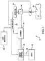
- the system 10 includes, but is not necessarily limited to, a laser source 14 capable of generating a pulsed laser beam 18, an energy control module 16 for varying the pulse energy of the pulsed laser beam 18, a scanner 20, a controller 22, a user interface 28, and focusing optics 28 that direct one or more focal points 30 of the pulsed laser beam 18 onto the surface of or within the eye 12 (e.g., sub-surface into the corneal region, such as sub-epithelium, sub-Bowman's layer, within the stroma, substantially adjacent to Descemet's membrane, and the like).
- a laser source 14 capable of generating a pulsed laser beam 18, an energy control module 16 for varying the pulse energy of the pulsed laser beam 18, a scanner 20, a controller 22, a user interface 28, and focusing optics 28 that direct one or more focal points 30 of the pulsed laser beam 18 onto the surface of or within the eye 12 (e.g., sub-surface into the corneal region, such as sub-epithelium, sub-Bowman's layer,
- the controller 22 (e.g., a processor operating suitable control software) communicates with one or more of the scanner 20, user interface 28, and focusing optics 28 to control the direction of the focal point 30 as it is scanned along the desired region of the eye.
- the user interface 28 provides the user with a variety of input parameters for controlling the system 10. For example, the pulsed laser beam 18 may be controlled based on one or more input parameters to produce a desired incision.
- the user interface 28 determines the type of corneal implant to be used for a particular ophthalmic procedure. Based on this determination, the controller 22 automatically configures the system 10 to a set of pre-determined operating values corresponding with the specific corneal implant. For customization (e.g., patient specific factors, historical performance, and the like), the user may modify one or more of these operating values via the user interface 28.
- software, firmware, or the like can be used (executed by the controller 22 to control or direct one or more components of the system 10) to command the actions and placement of the scanner via a motion control system, such as a closed-loop proportional integral derivative (PID) control system.
- a motion control system such as a closed-loop proportional integral derivative (PID) control system.
- the system 10 further includes a beam splitter 26 and a detector 24 coupled to the controller 22 to provide a feedback control mechanism for the pulsed laser beam 18.
- the beam splitter 26 and detector 24 may also be omitted in other embodiments, for example, with different control mechanisms.
- Movement of the focal point 30 of the pulsed laser beam 18 is accomplished via the scanner 20 in response to the controller 22.
- the scanner 20 scans the pulsed laser beam 18 to produce an incision in the desired region of the cornea.
- a chirped pulse laser amplification system such as described in U.S. Pat. No. RE37,585 , may be used for photoalteration.
- U.S. Pat. Publication No. 2004/0243111 also describes other methods of photoalteration.
- Other devices or systems may be used to generate pulsed laser beams. For example, non-ultraviolet (UV), ultrashort pulsed laser technology can produce pulsed laser beams having pulse durations measured in femtoseconds.
- UV non-ultraviolet
- ultrashort pulsed laser technology can produce pulsed laser beams having pulse durations measured in femtoseconds.
- U.S. Pat. No. 5,993,438 discloses a device for performing ophthalmic surgical procedures to effect high-accuracy corrections of optical aberrations.
- U.S. Pat. No. 5,993,438 discloses an intrastromal photodisruption technique for reshaping the cornea using a non-UV, ultrashort (e.g., femtosecond pulse duration), pulsed laser beam that propagates through corneal tissue and is focused at a point below the surface of the cornea to photodisrupt stromal tissue at the focal point.
- a non-UV, ultrashort e.g., femtosecond pulse duration
- the focusing optics 28 direct the pulsed laser beam 18 toward a region 12 of the eye (e.g., onto the cornea) for plasma mediated (e.g., non-UV) photoablation of superficial tissue on the eye, or into the stroma for intrastromal photodisruption of tissue.
- the system 10 is capable of generating the pulsed laser beam 18 with physical characteristics similar to those of the laser beams generated by a laser system disclosed in U.S. Pat. Nos. 4,764,930 and 5,993,438 , or the like.
- the system 10 can produce a non-UV, ultrashort pulsed laser beam for use as an incising laser beam.
- This pulsed laser beam preferably has laser pulses with durations as long as a few nanoseconds or as short as a few femtoseconds.
- the pulsed laser beam 18 has a wavelength that permits the pulsed laser beam 18 to pass through the cornea without absorption by the corneal tissue.
- the wavelength of the pulsed laser beam 18 is generally in the range of about 3 ⁇ m to about 1.9 nm, and preferably between about 400 nm to about 3000 nm.
- the irradiance of the pulsed laser beam 18 is preferably greater than the threshold for optical breakdown of the tissue.
- the pulsed laser beam 18 may have other pulse durations and different wavelengths in other embodiments (e.g., UV wavelengths for excimer applications and the like).
- Scanning is accomplished with the scanner 20 via the controller 22 by selectively moving the focal point(s) 30 to produce a structured scan pattern (e.g., a raster pattern, a spiral pattern, or the like) of scan spots. Operating the scanner 20 to scan this structured pattern is particularly useful for controlling the spacing between scan spots of the pattern.
- the step rate at which the focal point 30 is moved is referred to herein as the scan rate.
- the scanner 20 can operate at scan rates between about 10 kHz and about 400 kHz, or at any other desired scan rate.
- the scanner 20 generally moves the focal point of the pulsed laser beam 18 through the desired scan pattern at a substantially constant scan rate while maintaining a substantially constant separation between adjacent focal points. Further details of laser scanners are known in the art, such as described, for example, in U.S. Patent No. 5,549,632 .
- the scanner 20 includes, but is not necessarily limited to, a pair of scanning mirrors or other optics (not shown) to angularly deflect and scan input beam (e.g, the pulsed laser beam 18).
- scanning mirrors driven by galvanometers may be employed where each of the mirrors scans along different orthogonal axes (e.g., an x-axis and a y-axis).
- a focusing objective (not shown), having one or more lenses, images the input beam onto a focal plane of the system 10.
- the focal point 30 may thus be scanned in two dimensions (e.g., along the x-axis and the y-axis) within the focal plane of the system 10.
- Scanning along the third dimension i.e., moving the focal plane along an optical axis (e.g., a z-axis) may be achieved by moving the focusing objective, or one or more lenses within the focusing objective, along the optical axis.
- moving the focal plane along an optical axis e.g., a z-axis
- an area e.g., substantially circular, oval, or other shape
- the pulsed laser beam 18 photoalters the stromal tissue.
- the distribution of scan spots is generally determined by the pulse frequency, the scan rate, and the amount of scan line separation.
- higher scan rates enable shorter procedure times by increasing the rate at which corneal tissue can be photoaltered.
- the scan rates may be selected from a range between about 30 MHz and about 1 GHz with a pulse width in a range between about 300 picoseconds and about 10 femtoseconds, although other scan rates and pulse widths may be used.
- the system 10 may additionally acquire detailed information about optical aberrations to be corrected, at least in part, using the system 10. Examples of such detailed information include, but are not necessarily limited to, the extent of the desired correction, and the location in the cornea of the eye associated with the correction (e.g., where the correction can be made most effectively).
- the refractive power of the cornea may be used to indicate corrections.
- Wavefront analysis techniques made possible by devices such as a Hartmann-Shack type sensor (not shown), can be used to generate maps of corneal refractive power. Other wavefront analysis techniques and sensors may also be used (e.g., based on phase diversity or other techniques).
- the maps of corneal refractive power, or similar refractive power information provided by other means, such as corneal topographs or the like, can then be used to identify and locate the optical aberrations of the cornea that require correction.
- Optical aberration information acquired by other methods may also be utilized with the system 10, such as imaging techniques using optical coherence tomography (OCT) or other interferometric imaging schemes.
- OCT optical coherence tomography
- the focal spot 30 is selectively directed (e.g., via the scanner 20) along a beam path to photoalter stromal tissue.
- the focal spot 30 is moved along a predetermined length of the beam path in one reference area.
- the pulsed laser beam 18 is then redirected through another reference area, and the process of photoalteration is repeated.
- the sequence for directing the pulsed laser beam 18 through individually selected reference areas can be varied, and the extent of stromal tissue photoalteration while the incising laser beam is so directed, can be varied.
- the amount of photoalteration can be based on the refractive power map.
- the sequence of reference areas that is followed during a customized procedure will depend on the particular objectives of the procedure.
- the scanner 20 may also scan a predetermined pattern using one or more scan patterns to one or more combinations of these reference areas or scan a single line (e.g., to produce a sidecut or continuous incision).
- a predetermined pattern is the creation of a cavity or a pocket in the cornea.
- the laser focal spot 30 of the pulsed laser beam 18 may be scanned at a pre-determined subsurface depth of the cornea (e.g., such as sub-epithelium, sub-Bowman's layer, within the stroma, substantially adjacent to Descemet's membrane, and the like) to form a pocket bed.
- An incision may be made to connect the surface of the eye with the pocket bed.
- the desired corneal implant or specific component of a multi-component corneal implant, is then inserted through this incision.
- additional incisions may be made to connect the surface of the eye with the pocket bed.
- intrastromal tissue is photoaltered by the system 10 so as to create an isolated lenticle of intrastromal tissue, and the lenticle of tissue can then be removed from the cornea (e.g., through the incision) to create the pocket.
- the incision selection may be based at least in part on the alteration of the shape of the cornea as particular to the vision correction procedure.
- LASIK laser assisted in-situ keratomilieusis
- a flap is cut from the cornea to establish extracorporeal access to the tissue that is to be photoaltered.
- the flap may be created using random scanning or one or more scan patterns of pulsed laser beams.
- a sidecut is created around a desired perimeter of the flap such that the ends of the sidecut terminate, without intersection, to leave an uncut segment. This uncut segment serves as a hinge for the flap.
- the flap is separated from the underlying stromal tissue by scanning the laser focal point across a resection bed, the perimeter of which is approximately defined by and slightly greater than the sidecut.
- the sidecut may be created completely around a desired perimeter (e.g., with the ends terminating with one another) to separate a portion of corneal tissue (e.g., for corneal transplant or the like) from the cornea.
- a desired perimeter e.g., with the ends terminating with one another
- corneal tissue e.g., for corneal transplant or the like
- ophthalmic procedures may be combined to complement the optical benefits provided by the desired corneal implant with the refractive corrections provided by LASIK, corneal transplants, or a variety of other ophthalmic procedures.
- a corneal flap may be formed followed by photoalteration of the flap bed (e.g., creation of a custom-shaped regions) to receive the inlay or implant.
- FIG. 2 is a block diagram of an ophthalmic laser system 70 in accordance with another embodiment of the present invention.
- the ophthalmic laser system 70 illustrates the optical path of the pulsed laser beam in greater detail and includes, but is not necessarily limited to, a laser source 32 providing a pulsed laser beam (e.g. from the laser 14 shown in FIG. 1 ), a beam monitoring and processing module 40, a beam delivery module 50, and a user interface 60.
- the pulsed laser beam is supplied to the beam monitoring and processing module 40 where operating characteristics of the pulsed laser beam are controlled, such as the pulse energy (e.g., varied by the energy control module 16 shown in FIG. 1 ), a focal point separation, a minimum sub-surface depth of the pulsed laser beam, and the like).
- the beam delivery module 50 scans the pulsed laser beam along a desired scan region.
- the ophthalmic laser system 70 can be coupled to an eye 64 via a patient interface 62, and the patient interface 62 may be coupled to the ophthalmic laser system 70 at a loading deck 58, for example.
- a display is provided by the user interface 60 for viewing the eye 64 undergoing laser treatment.
- the beam monitoring and processing module 40 includes, but is not necessarily limited to, an energy attenuator 34, one or more energy monitors 36, and an active beam positioning mirror 38.
- the pulsed laser beam is directed from the laser source 32 to the energy attenuator 34, then to the energy monitor 36, and then to the active beam positioning mirror 38.
- the active beam positioning mirror 38 directs the pulsed laser beam from the beam monitoring and processing module 40 to the beam delivery module 50.
- the pulse energy of the pulsed laser beam may be varied to desired values.
- the spatial separation of the focal points of the pulsed laser beam may be varied by the beam monitoring and processing module 40.
- the beam delivery module 50 scans the pulsed laser beam at the desired scan region (e.g., a sub-surface region of the eye 64, such as within the corneal epithelium and on or within Bowman's layer, the stroma, Descemet's membrane, the endothelium, and the like).
- the beam delivery module 50 includes, but is not necessarily limited to, a beam position monitor 42, an x-y scanner 44 (e.g., such as the scanner 20 shown in FIG. 1 ), a beam expander 46, one or more beam splitters 52, and a z-scanning objective 56.
- the beam delivery module 50 additionally includes an operating microscope 48 and a video camera 54 to enhance viewing of the eye 64.
- the pulsed laser beam is received from the beam monitoring and processing module 40 by the x-y scanner 44 and directed to the beam expander 46, and the beam expander 46 directs the pulsed laser beam to the z-scanning objective via the beam splitter(s) 52.
- the z-scanning objective 56 can vary the focal point depth of the pulsed laser beam.
- the z-scanning objective 56 can vary the focal point depth to the minimum focal point depth determined for the eye 64 or the desired region of the eye 64 and for the selected operating pulse energy and operating focal point separation.
- the configuration of the ophthalmic laser system 70 may vary as well as the organization of the various components and sub-components of the ophthalmic laser system 70.
- some sub-components of the beam delivery module 50 may be incorporated with the beam monitoring and processing module 40 and vice versa.
- the user interface 28 presents a variety of corneal implant options for selection by the user.
- the user interface 28 includes, but is not necessarily limited to, a display and an input device, such as a touch-screen, a mouse, a keyboard, a touch-pad, or the like. Multiple images representing different types of corneal implants are presented on the display, and the user may select the appropriate corneal implant for a particular ophthalmic procedure. For example, the user may indicate a corneal implant selection by touching the image on the touch-screen corresponding with the appropriate corneal implant.
- a variety of pre-programmed and updateable incisions are available to the system 10, 70 for forming an appropriate cavity in the cornea to receive the selected corneal implant.
- incisions associated with IntraLase ® enabled keratoplasty (IEK) and other lamellar keratoplasty or penetrating keratoplasty procedures may be incorporated as part of a suite of pre-programmed incisions utilized by the system 10, 70.
- INK IntraLase ® enabled keratoplasty
- other lamellar keratoplasty or penetrating keratoplasty procedures may be incorporated as part of a suite of pre-programmed incisions utilized by the system 10, 70.
- the user interface 28 includes, but is not necessarily limited to, a read device, such as a radio frequency identification (RFID) interrogator, a bar code scanner, and the like.
- RFID radio frequency identification
- the user simply positions the actual corneal implant label or packaging for identification by the read device.
- the corneal implant may be packaged with an RFID tag.
- RFID interrogator the identification may be made by positioning the packaging within proximity of the RFID interrogator.
- the corneal implant may be packaged with a bar code on the exterior of the packaging. With a bar code scanner, the identification may be made by positioning the bar code within scanning range of the bar code scanner.
- the controller 22 selects a pre-determined procedure, corresponding with the identified corneal implant, from among a stored database of pre-determined procedures.
- FIG. 3 an ophthalmic laser system 80 is shown illustrating corneal implant related communication or data flow in accordance with one embodiment.
- the ophthalmic laser system 80 includes, but is not necessarily limited to, a central processing unit (CPU) 82, a display 84 coupled to the CPU 82, a laser assembly 86 coupled to the CPU 82, a memory 88 having a database 96, 98, 100, 102 coupled to the CPU 82, and an input/output (IO) device 90 coupled to the CPU 82.
- CPU central processing unit
- a display 84 coupled to the CPU 82
- a laser assembly 86 coupled to the CPU 82
- a memory 88 having a database 96, 98, 100, 102 coupled to the CPU 82
- an input/output (IO) device 90 coupled to the CPU 82.
- the display 84 may have a touch-sensitive screen, as previously mentioned regarding the user interface 28 shown in FIG. 1 .
- a user input device 92 e.g., a mouse, a keyboard, a touch-pad, and the like
- a read unit 94 e.g., RFID interrogator, bar code scanner, and the like
- the user input device 92 facilitates user selection of the desired corneal implant type
- the read unit 94 facilitates identification of the desired corneal implant type.
- the memory 88 also stores an operating system module and a graphical user interface (GUI) module.
- the operating system module may include executable instructions for handling various system services, such as file services or for performing hardware dependant tasks.
- the GUI module may rely upon standard techniques to produce graphical components on the display 84, e.g., windows, icons, buttons, menus, drop-down menus, and the like, examples of which are discussed below.
- the GUI module may include executable instructions to receive input from a pointer device (e.g., a mouse, a keyboard, a touch-pad, and the like) or touch-screen and display a cursor on the display 84. Additionally, the GUI module includes executable instructions for selecting items in the GUI.
- the executable modules stored in memory 88 are exemplary. It should be appreciated that the functions of the modules may be combined or divided into additional modules.
- the identification of the desired corneal implant type is determined by user selection on the touch-sensitive screen of the display 84, determined by user input via the user input device 92, or detected by the read unit 94 and communicated to the CPU 82. With the identification, the CPU 82 retrieves a pre-determined incision procedure from the database 96, 98, 100, 102.
- the database includes a catalog of corneal implant types 96 and a catalog of pre-determined incision procedures 98. Although described with catalogs, the database may be implemented with one or more look-up tables or other data management configurations. Each of the incision procedures corresponds to a different corneal implant type, and the catalogs 96 and 98 may be periodically updated via the IO device 90.
- the IO device 90 is a media-specific reader or multimedia reader compatible with a variety of memory storage devices (e.g., flash memory, portable disk drive, floppy disk, memory stick, compact disc, and the like).
- the IO device 90 may have network connectivity, such as to another network capable device (e.g., laptop computer, desktop computer, notebook computer, portable computer, and the like) or the Internet, via a standard network connection or wireless connection.
- additional corneal implant types and corresponding incision procedures are accessible by the IO device 90. For example, new corneal implant types and the corresponding incision procedures may be down-loaded via the media reader or retrieved from the Internet and entered into the catalogs 96 and 98, respectively.
- Obsolete corneal implant types may also be removed from the catalogs 96 and 98 based on the updated information. Additionally, the catalogs 96, 98 may be customizable (e.g., in general, for all selections associated with a type of procedure and/or individually by patient).
- the catalog of corneal implant types 96 includes a variety of implant types (e.g., a Type 1 implant, a Type 2 implant, ..., and a Type N implant).
- the incision procedures in the catalog of incision procedures 98 may be similarly designated for association with the corresponding corneal implant type, although a particular incision procedure may be applicable to more than one of the corneal implant types.
- Some examples of corneal implant types include, but are not necessarily limited to, a variety of discs with varying radii of curvatures associated with the anterior and/or posterior surfaces of the disc and/or with varying cross-sectional shapes, single or multi-perforated discs, multi-component implants, crescents, rings, lenses, and the like.
- corneal implant types may be derived from variants of these examples based on pre-determined sizes or dimensions. Combinations of corneal implant types and incisions to provide refractive corrections may also be cataloged. In one embodiment, the corneal implant types are presented on the display 84 as user-selectable representations (e.g., names, images, icons, buttons, and the like).
- each corneal implant type is associated with specific physical characteristics or properties, such as dimensions (e.g., width, height, thickness, shape, profile, diameter, and the like), material of construction, elasticity, hardness, material strength, and the like, at least some of which are used to pre-determine various aspects of the corresponding incision procedure.
- dimensions e.g., width, height, thickness, shape, profile, diameter, and the like
- material of construction e.g., elasticity, hardness, material strength, and the like
- the dimensions of a corneal implant type may be used to pre-program incision parameters (e.g., length, depth, volume, shape, and the like) to be produced by the incision procedure.
- the incision procedure is preferably pre-programmed to produce a cavity that conforms to the shape of the desired corneal implant type and permits insertion of the desired corneal implant.
- the dimensions and characteristics of each corneal implant in the catalog 96 are used to program software that operates the laser assembly 86 to cut a cavity or pocket for receiving the corresponding corneal implant.
- the incision parameters are presented on the display 84 and may be modified by the user (e.g., for customized ophthalmic procedures).
- drop-down menus, input blocks, incremental blocks, and the like may be used to set or modify one or more incision parameters (e.g., default incision parameter settings), the number and/or type of incisions, and the like associated with the particular incision procedure.
- incision parameters e.g., default incision parameter settings
- the number and/or type of incisions, and the like associated with the particular incision procedure are modifications.
- customization may be based on wavefront analysis, OCT maps, pupil dynamics (e.g., to assist with centration, incision selection, and/or implant selection), centration, iris registration, and the like.
- Refractive corrections may change over time. Multiple photoablations of the cornea over a long duration may not be feasible because of the limited amount of corneal tissue and/or the integrity of the cornea. Additionally, the patient's corneal stromal bed may not be sufficient for ablation with a particular refractive procedure.
- the refractive characteristics associated with the selected corneal implant may be altered by the laser assembly 86 to fine-tune the overall refractive correction provided by the corneal implant. This may be performed immediately following implant or at a subsequent time. Multiple refractive adjustments may be performed on the patient's corneal implant using the prior knowledge of the corneal implant characteristics or properties.
- the corneal implant, and associated incisions and cavity, for a particular patient may be stored by the system 10, 70, 80 for subsequent recall and additional refractive correction (e.g., removal of the implant, exchange of the implant, ablation of the implant, and the like, for over or under correction, long-term refractive error correction, provision of monovision for presbyopic relief, and the like).
- additional refractive correction e.g., removal of the implant, exchange of the implant, ablation of the implant, and the like, for over or under correction, long-term refractive error correction, provision of monovision for presbyopic relief, and the like.
- the corneal implant may be selected to provide a gross refractive correction (e.g., by modifying lens shape, thickness, and/or refractive index differences), and surface corneal implant laser ablation can provide fine-tuning or refractive error and higher order aberrations.
- Myopic patients retaining the option for future monovision correction to relieve presbyopia symptoms may opt for a partial correction of the myopic prescription and correct the remaining myopia (e.g., from about -0.75D to about -2.50D correction) via a corneal implant. Over time as presbyopia effects increase, the myopic patient can seek to remove the corneal implant and result in a low myopic eye with monovision effect.
- a thirty-five (35) year old patient with -6.00D for both eyes can have a -6.00D correction via photoalteration of the dominant eye and a -4.00D correction of the non-dominant corneal stroma via photoalteration with a -2.00D correction via a corneal inlay (e.g., lens shape or ablation of the inlay).
- the inlay may be subsequently removed at a presbyopic year to result in a -2.00 myopia on the non-dominant eye and a 2.00D add monovision.
- Post-LASIK patients desiring monovision correction without cornea ablation may select a corneal implant to create a low degree of myopia in one eye to provide near visual relief.
- a fifty-five (55) year old post-LASIK patient with piano refraction desiring monovision to relieve presbyopic symptoms can have a corneal inlay with +1.50D correction implanted under the LASIK flap on one eye (e.g., the non-dominant eye).
- Patients with adult on-set myopia or progressive myopia may increase myopic refractive error over time during adulthood.
- Full or partial correction may be performed on the cornea during a first photoablation with an intra-corneal lens/corneal inlay procedure used for future fine tuning via photoablation on the intra-corneal lens/corneal inlay.
- the lenses/inlays may be removed and exchanged with different lenses/inlays (e.g., adjusted lens diameter, thickness curvature, and/or refractive index) to provide better myopic effect.
- a hyperopic patient with a cycloplegic refraction significantly greater than the manifest refraction is generally classified as latent hyperopia.
- Patients with latent hyperopia may not tolerate full refractive correction.
- a latent hyperope without full correction may experience hyperopic progression as accommodation relaxes or declines with aging.
- the manifest refraction is corrected or the two refractions are averaged. Further correction may be needed as the patient gets used to the correction and/or the accommodation is relaxed or reduced.
- Full or partial correction on the cornea may be performed during the first photoablation, and an intra-corneal lens may be implanted for future fine tuning via ablation on the intra-corneal lens.
- a twenty-five (25) year old patient with +2.00D manifest refraction and +3.50 D cycloplegic refraction can have +3.50D correction via photoablation on the cornea with -0.75D correction (e.g., half of the refraction discrepancy) provided by a corneal inlay (e.g., via ablation of the inlay or lens shape).
- a corneal inlay e.g., via ablation of the inlay or lens shape.
- This combination provides the patient with a total of +2.75D correction.
- the corneal inlay may be subsequently remove to provide a total of +3.50D correction for a full refractive correction.
- the inlay may be photoablated or exchanged.
- Intra-corneal inlays can also be used to provide partial correction or gross correction in combination with corneal photoablation for fine correction, including higher order aberrations, for patients with thin corneas that may not have sufficient residual stromal bed following photoablation.
- the system 10, 70, 80 may be used for the photoablative refractive corrections on or in the cornea and one or in the corneal implant.
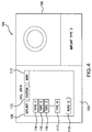
- FIG. 4 is an elevational view of a display screen 104 illustrating a graphical user interface in accordance with one embodiment.
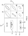
- FIG. 5 is an elevational view of a display screen 120 illustrating a graphical user interface in accordance with another embodiment.
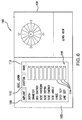
- FIG. 6 is an elevational view of a display screen 140 illustrating a graphical user interface in accordance with another embodiment.
- the screens 104, 120, 140 may each be displayed on the user interface 28 ( FIG. 1 ) or 60 ( FIG. 2 ), the display 84 ( FIG. 3 ), or the like and is partitioned into multiple areas.
- the GUI includes, but is not necessarily limited to, a first area 105 of the screen 104 and a second area 106 of the screen 104.
- the first area 105 presents general system operating parameters and navigation tools
- the second area 106 presents a representation (e.g., a photo image) of a selected corneal implant.
- the first area 105 provides tabbed pages 108, 110, 112 (e.g., an IMPLANT tabbed page 108, a CUSTOM tabbed page 110, and a MAIN tabbed page 112) of various system operating parameters for selection, entry of parameter values, modification, or any combination thereof.
- the type and variety of tabbed pages may vary based on user convenience, ergonomics, other ease-of use considerations, or the like. Additionally, the organization of the graphical user interface may vary.
- the tabbed pages 108, 110, 112 may be substituted by a toolbar providing the general system operating parameters with drop-down menus for each of the parameters.
- the screens 104, 120, 140 may also include additional windows, such as for eye images and diagnostics displays (e.g., OCT, wavefront analysis, and the like).
- selection of a particular selectable item presented on the display screen 104 may be performed by the user input device 92 ( FIG. 3 ), by a touch-screen coupled with the display 84 ( FIG. 3 ), or the like.
- the IMPLANT tabbed page 108 has been selected and lists buttons 114, 115, 116, 117 corresponding with the different corneal implant types (e.g., Type 1, Type 2, Type 3, ..., and Type N) available for selection. Selecting one of the other tabbed pages (e.g., the tabbed pages 110 or 112) would display parameters corresponding with the tabbed page.
- Each of the corneal implant types on the IMPLANT page 108 is represented by a selectable button.
- a first button 114 represents the Type 1 implant
- a second button 115 represents the Type 2 implant
- a third button 116 represents the Type 3 implant
- another button 117 represents the Type N implant.
- the button 116 indicates that the Type 3 implant has been selected, and a representation (e.g., a photograph or other image) of the Type 3 implant is presented in the second area 106. Additional parameters and navigation tools may also be presented on the display screen 104.
- an AUTO ID button 118 is presented in the first area 105.
- the identification of the corneal implant type may be determined via the read unit 94 ( FIG. 3 ) (e.g., by RFID, bar code scanning, or the like).
- the incision type may be displayed for confirmation with the selected implant.
- an alert may be provided by the display 84 in the event that the corneal implant type does not match with the particular incision.
- the GUI includes, but is not necessarily limited to, a first area 121 of the screen 120, a second area 123 of the screen 120, and a third area 125 of the screen 120.
- the first area 121 presents a prompt for implant selection
- the second area 123 presents navigational tools (e.g., a BACK button 136 for returning to a previously displayed screen and a NEXT button 138 for advancing to a subsequent screen)
- the third area 125 presents representations (e.g., images) of a selected corneal implant for user selection.
- the third area 125 includes, but is not necessarily limited to, a first selectable image 122 representing a corneal implant with a central pin-hole, a second selectable image 124 representing a ring implant, a third selectable image 126 representing a two-piece corneal implant, a fourth selectable image 128 representing a disc or a lens, a fifth selectable image 130 representing a small disc or lens, and a sixth selectable image 132 representing a substantially planar disc or lens.
- the corneal implants shown in FIG. 5 are merely exemplary, and other types of corneal implants may be substituted for one or more of the selectable images 122, 124, 126, 128, 130, 132 or included as part of a larger collection displayed over this screen 120 and other screens.
- the GUI includes, but is not necessarily limited to, a first area 141 of the screen 140 and a second area 142 of the screen 140.
- the first area 141 is similar to the first area 105 shown in FIG. 4 and presents general system operating parameters and navigation tools.
- the second area 142 provides a view of the patient's eye, such as via the video camera 54 shown in FIG. 2 .
- the CUSTOM tabbed page 110 has been selected and lists various incision parameters (e.g., depth, diameter, bed energy, side pattern, side depth, side energy, side angle, hinge, spot separation, and line separation), which are exemplary and not inclusive. Each of these parameters is associated with an entry block 144 that displays a current parameter setting.
- One or more of these parameter settings may be modified using incremental arrows 146 associated with each block 144.
- the entry blocks 144 display parameter settings (e.g., default values stored in the catalog 98 shown in FIG. 3 ) associated with incision procedure corresponding with the selected or identified corneal implant type. These parameter settings may be increased by selecting an upward arrow and decreased by selecting a downward arrow.
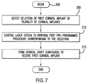
- FIG. 7 is a flow diagram of a method 200 for ophthalmic surgery given as an example not part of the invention.
- a selection of a first corneal implant of a plurality of corneal implants is detected, as indicated at step 205.
- a plurality of items representing a plurality of corneal implants is displayed.
- selection of a first item from the plurality of items is detected, where the first item represents the first corneal implant.
- the items may be the selectable buttons 114, 115, 116, 117 provided on the screen 104, or the selectable images 122, 124, 126, 128, 130, 132 provided on the screen 120, for example.
- a first identification of a plurality of identifications is detected, where the first identification represents the first corneal implant.
- the read unit 94 detects the identification associated with a desired corneal implant by scanning a bar code on the packaging for the desired corneal implant, interrogating an RFID tag included in the packaging for the desired corneal implant, or the like.
- a laser system is controlled to perform a first pre-programmed procedure corresponding to the selection, as indicated at step 210.
- the CPU 82 selects and retrieves the corresponding incision procedure from the incision catalog 98 corresponding with the selected corneal implant.
- the CPU 82 controls the laser assembly 86 to perform the corresponding incision procedure.
- a corneal cavity configured to receive the first corneal implant is formed, as indicated at step 215, and the corneal implant may be implanted in the corneal cavity.
- systems, graphical user interfaces, and methods for ophthalmic surgery that operate with and manage multiple corneal implant types, establish a corneal pocket suitable for accommodating a selected corneal implant, and/or automatically select a pre-programmed incision procedure based on a corneal implant desired for implantation.
- additional refractive eye surgery applications for the systems 10, 70, and 80 include, but are not necessarily limited to, photorefractive keratectomy (PRK), LASIK, laser assisted sub-epithelium keratomileusis (LASEK), corneal transplant, intraocular lens or the like.
- PRK photorefractive keratectomy
- LASIK laser assisted sub-epithelium keratomileusis
- corneal transplant intraocular lens or the like.
- the systems 10, 70, and 80 are capable of forming a corneal pocket for receiving a corneal implant, the systems 10, 70, and 80 may also be used to form cavities within various regions of the eye, such as for intraocular lens procedures and the like.
Description
- The field of the present invention is generally related to corneal implants and more particularly, to corneal implant systems, interfaces, and methods.
- Intracorneal implants have been developed in an attempt to correct abnormalities of the eye. The intracorneal implant may be implanted or inserted into a desired region of the cornea, such as within the stroma of the cornea. In one technique, a stromal pocket is created by making an incision in the stromal layer of the cornea or by removing a small amount of stromal tissue during the implant procedure. The implant is typically placed in the stromal pocket to reshape the cornea, alter refractive properties of the cornea, or both.
- In the past, stromal pockets have been prepared to accommodate implants by mechanically incising and separating corneal lamellae. For example, stromal pockets may be manually prepared to accommodate lens and disk-shaped corneal implants. More recently, surgical lasers using pulsed laser beams have been used to incise corneal tissue for a variety of ophthalmic procedures, such as to produce corneal flaps. Typically, the surgical laser is programmed to perform one or more specific incisions to scan a stromal bed circumscribed by an edge to create a corneal flap.
- Many different types of corneal implants are currently available or in development. For example, corneal rings, such as a single continuous annular ring, two half-ring components, a ring segment, a pair of crescent-shaped corneal implants, or a variety of other shaped implants, either single or multi-component types, can also be embedded within the stromal tissue (e.g., surrounding a central optical zone of the cornea). Development continues for additional implants having different shapes and configurations.
- Accordingly, it is desirable to provide systems and methods for ophthalmic laser surgery that operate with and manage multiple corneal implant types. It is also desirable to provide systems and methods for establishing a corneal pocket or other retaining region suitable for accommodating a selected corneal implant. It is also desirable to provide systems and methods for modifying and customizing the characteristics of the corneal pocket or other retaining region once identified for the selected corneal implant. It is further desirable to provide systems and methods for corneal laser surgery that automatically selects a pre-programmed incision procedure based on a corneal implant desired for implantation. Additionally, other desirable features and characteristics of the present invention will become apparent from the subsequent detailed description and the appended claims, taken in conjunction with the accompanying drawings and the foregoing technical field and background.
-
WO 03/005920 A1 - The present invention is as defined in the independent claims and is directed towards systems and graphical user interfaces. In one embodiment, a system is provided including a display operable to present a plurality of images representing a plurality of corneal implants, a laser assembly operable to output a pulsed laser beam, and a control unit coupled to the laser assembly and the display. The control unit is configured to direct the laser assembly in response to a selected image of the plurality of images to produce a cavity in the cornea via the pulsed laser beam. The cavity is configured to receive a first corneal implant of the plurality of corneal implants corresponding to the selected image.
- In another embodiment, a graphical user interface renderable by a display device within a graphical window is provided. The interface includes a first area to facilitate a specification of a corneal implant from a plurality of corneal implants, and a second area to facilitate a specification of one or more incision properties. The second area is modified in response to the specification of the corneal implant.
- In another embodiment, a system is provided for incising a cornea. The system includes a read unit operable to determine an identification representing a corneal implant, a laser assembly operable to output a pulsed laser beam, and a control unit coupled to the read unit and the laser assembly. The control unit is configured to direct the laser assembly to form a cavity in the cornea via the pulsed laser beam based on the identification. The cavity is configured to receive the corneal implant.
- In the drawings, wherein like reference numerals refer to similar components:
-
FIG. 1 is a block diagram of an ophthalmic laser system in accordance with one embodiment of the present invention; -
FIG. 2 is a schematic diagram of an ophthalmic laser system in accordance with another embodiment; -
FIG. 3 is a block diagram of an ophthalmic laser system in accordance with another embodiment; -
FIG. 4 is an elevational view of a display screen illustrating a graphical user interface in accordance with one embodiment; -
FIG. 5 is an elevational view of a display screen illustrating a graphical user interface in accordance with another embodiment; -
FIG. 6 is an elevational view of a display screen illustrating a graphical user interface in accordance with another embodiment; -
FIG. 7 is a flow diagram of a method for ophthalmic surgery given as an example. - The present invention provides systems and graphical user interfaces for ophthalmic surgery. More particularly, the present invention provides systems and graphical user interfaces for ophthalmic surgery with corneal implants (e.g., inlays, onlays, and the like). In one embodiment, the system determines or detects the type of corneal implant desired to be implanted, selects a pre-programmed procedure from among a group of updateable pre-programmed procedures, and directs a laser assembly to produce a cavity in the cornea using a pulsed laser beam. The selected pre-programmed procedure corresponds with the desired corneal implant, and the resulting cavity corresponds with the desired corneal implant (e.g., conforms to the shape, material properties, and/or the like, associated with the desired corneal implant). A user may optionally modify the pre-programmed procedure to customize the resulting cavity.
- In general, photoalteration of a material may be accomplished using a pulsed laser beam that is directed (e.g., via a scanner) at a desired region of the material. For example, a pulsed laser beam may be controlled to scan the desired region (e.g., on the surface or sub-surface) and to create a separation of the material (e.g., which may be used to produce a flap of the material, to separate a portion of the material for transplants, or for a variety of other uses). Typically, a pulsed laser beam is focused onto a desired area of the material to photoalter the material in this area and, in some instances, the associated peripheral area. Examples of photoalteration of the material include, but are not necessarily limited to, chemical and physical alterations, chemical and physical breakdown, disintegration, ablation, vaporization, or the like. Although various embodiments of systems, graphical user interfaces, and methods for ophthalmic surgery are described, these systems, graphical user interfaces, and methods may be applied to other biological tissues and other materials.
- One example of photoalteration using pulsed laser beams is the photodisruption (e.g., via laser induced optical breakdown) of a material. Localized photodisruptions can be placed at or below the surface of the material to produce high-precision material processing. For example, a micro-optics scanning system may be used to scan the pulsed laser beams to produce an incision in the material and create a flap, a pocket, or a cavity therefrom. The term "scan" or "scanning" refers to the movement of the focal point of the pulsed laser beam along a desired path (e.g., along an x-axis, a y-axis, a z-axis, or any combination thereof) or in a desired pattern.
- Referring to the drawings, an
ophthalmic laser system 10 is shown inFIG. 1 . Thesystem 10 includes, but is not necessarily limited to, alaser source 14 capable of generating apulsed laser beam 18, anenergy control module 16 for varying the pulse energy of thepulsed laser beam 18, ascanner 20, acontroller 22, auser interface 28, and focusingoptics 28 that direct one or morefocal points 30 of thepulsed laser beam 18 onto the surface of or within the eye 12 (e.g., sub-surface into the corneal region, such as sub-epithelium, sub-Bowman's layer, within the stroma, substantially adjacent to Descemet's membrane, and the like). The controller 22 (e.g., a processor operating suitable control software) communicates with one or more of thescanner 20,user interface 28, and focusingoptics 28 to control the direction of thefocal point 30 as it is scanned along the desired region of the eye. Theuser interface 28 provides the user with a variety of input parameters for controlling thesystem 10. For example, thepulsed laser beam 18 may be controlled based on one or more input parameters to produce a desired incision. In one embodiment, theuser interface 28 determines the type of corneal implant to be used for a particular ophthalmic procedure. Based on this determination, thecontroller 22 automatically configures thesystem 10 to a set of pre-determined operating values corresponding with the specific corneal implant. For customization (e.g., patient specific factors, historical performance, and the like), the user may modify one or more of these operating values via theuser interface 28. - In one embodiment, software, firmware, or the like, can be used (executed by the
controller 22 to control or direct one or more components of the system 10) to command the actions and placement of the scanner via a motion control system, such as a closed-loop proportional integral derivative (PID) control system. In this embodiment, thesystem 10 further includes abeam splitter 26 and adetector 24 coupled to thecontroller 22 to provide a feedback control mechanism for thepulsed laser beam 18. Thebeam splitter 26 anddetector 24 may also be omitted in other embodiments, for example, with different control mechanisms. - Movement of the
focal point 30 of thepulsed laser beam 18 is accomplished via thescanner 20 in response to thecontroller 22. In one embodiment, thescanner 20 scans thepulsed laser beam 18 to produce an incision in the desired region of the cornea. To provide thepulsed laser beam 18, a chirped pulse laser amplification system, such as described inU.S. Pat. No. RE37,585 , may be used for photoalteration.U.S. Pat. Publication No. 2004/0243111 also describes other methods of photoalteration. Other devices or systems may be used to generate pulsed laser beams. For example, non-ultraviolet (UV), ultrashort pulsed laser technology can produce pulsed laser beams having pulse durations measured in femtoseconds. Some of the non-UV, ultrashort pulsed laser technology may be used in ophthalmic applications. For example,U.S. Pat. No. 5,993,438 discloses a device for performing ophthalmic surgical procedures to effect high-accuracy corrections of optical aberrations.U.S. Pat. No. 5,993,438 discloses an intrastromal photodisruption technique for reshaping the cornea using a non-UV, ultrashort (e.g., femtosecond pulse duration), pulsed laser beam that propagates through corneal tissue and is focused at a point below the surface of the cornea to photodisrupt stromal tissue at the focal point. - In this case, the focusing
optics 28 direct thepulsed laser beam 18 toward aregion 12 of the eye (e.g., onto the cornea) for plasma mediated (e.g., non-UV) photoablation of superficial tissue on the eye, or into the stroma for intrastromal photodisruption of tissue. Thesystem 10 is capable of generating thepulsed laser beam 18 with physical characteristics similar to those of the laser beams generated by a laser system disclosed inU.S. Pat. Nos. 4,764,930 and5,993,438 , or the like. For example, thesystem 10 can produce a non-UV, ultrashort pulsed laser beam for use as an incising laser beam. This pulsed laser beam preferably has laser pulses with durations as long as a few nanoseconds or as short as a few femtoseconds. For intrastromal photodisruption of the tissue, thepulsed laser beam 18 has a wavelength that permits thepulsed laser beam 18 to pass through the cornea without absorption by the corneal tissue. The wavelength of thepulsed laser beam 18 is generally in the range of about 3 µm to about 1.9 nm, and preferably between about 400 nm to about 3000 nm. For accomplishing photodisruption of stromal tissues at the focal point, the irradiance of thepulsed laser beam 18 is preferably greater than the threshold for optical breakdown of the tissue. Although a non-UV, ultrashort pulsed laser beam is described in this embodiment, thepulsed laser beam 18 may have other pulse durations and different wavelengths in other embodiments (e.g., UV wavelengths for excimer applications and the like). - Scanning is accomplished with the
scanner 20 via thecontroller 22 by selectively moving the focal point(s) 30 to produce a structured scan pattern (e.g., a raster pattern, a spiral pattern, or the like) of scan spots. Operating thescanner 20 to scan this structured pattern is particularly useful for controlling the spacing between scan spots of the pattern. The step rate at which thefocal point 30 is moved is referred to herein as the scan rate. For example, thescanner 20 can operate at scan rates between about 10 kHz and about 400 kHz, or at any other desired scan rate. In one embodiment, thescanner 20 generally moves the focal point of thepulsed laser beam 18 through the desired scan pattern at a substantially constant scan rate while maintaining a substantially constant separation between adjacent focal points. Further details of laser scanners are known in the art, such as described, for example, inU.S. Patent No. 5,549,632 . - In one embodiment, the
scanner 20 includes, but is not necessarily limited to, a pair of scanning mirrors or other optics (not shown) to angularly deflect and scan input beam (e.g, the pulsed laser beam 18). For example, scanning mirrors driven by galvanometers may be employed where each of the mirrors scans along different orthogonal axes (e.g., an x-axis and a y-axis). A focusing objective (not shown), having one or more lenses, images the input beam onto a focal plane of thesystem 10. Thefocal point 30 may thus be scanned in two dimensions (e.g., along the x-axis and the y-axis) within the focal plane of thesystem 10. Scanning along the third dimension, i.e., moving the focal plane along an optical axis (e.g., a z-axis), may be achieved by moving the focusing objective, or one or more lenses within the focusing objective, along the optical axis. - For ophthalmic applications (e.g., preparing a cornea for flap separation, corneal transplant, preparing a pocket or cavity in the cornea, or the like), an area (e.g., substantially circular, oval, or other shape) may be scanned with a scan pattern based on the movement of the scanning mirrors. As the
focal point 30 is scanned along a corneal bed, thepulsed laser beam 18 photoalters the stromal tissue. Using structured patterns, the distribution of scan spots is generally determined by the pulse frequency, the scan rate, and the amount of scan line separation. Generally, higher scan rates, enable shorter procedure times by increasing the rate at which corneal tissue can be photoaltered. For example, the scan rates may be selected from a range between about 30 MHz and about 1 GHz with a pulse width in a range between about 300 picoseconds and about 10 femtoseconds, although other scan rates and pulse widths may be used. - The
system 10 may additionally acquire detailed information about optical aberrations to be corrected, at least in part, using thesystem 10. Examples of such detailed information include, but are not necessarily limited to, the extent of the desired correction, and the location in the cornea of the eye associated with the correction (e.g., where the correction can be made most effectively). The refractive power of the cornea may be used to indicate corrections. Wavefront analysis techniques, made possible by devices such as a Hartmann-Shack type sensor (not shown), can be used to generate maps of corneal refractive power. Other wavefront analysis techniques and sensors may also be used (e.g., based on phase diversity or other techniques). The maps of corneal refractive power, or similar refractive power information provided by other means, such as corneal topographs or the like, can then be used to identify and locate the optical aberrations of the cornea that require correction. Optical aberration information acquired by other methods may also be utilized with thesystem 10, such as imaging techniques using optical coherence tomography (OCT) or other interferometric imaging schemes. - In general, when the
laser source 14 is activated, thefocal spot 30 is selectively directed (e.g., via the scanner 20) along a beam path to photoalter stromal tissue. For example, thefocal spot 30 is moved along a predetermined length of the beam path in one reference area. Thepulsed laser beam 18 is then redirected through another reference area, and the process of photoalteration is repeated. The sequence for directing thepulsed laser beam 18 through individually selected reference areas can be varied, and the extent of stromal tissue photoalteration while the incising laser beam is so directed, can be varied. Specifically, as indicated above, the amount of photoalteration can be based on the refractive power map. On the other hand, the sequence of reference areas that is followed during a customized procedure will depend on the particular objectives of the procedure. - The
scanner 20 may also scan a predetermined pattern using one or more scan patterns to one or more combinations of these reference areas or scan a single line (e.g., to produce a sidecut or continuous incision). One example of an ophthalmic scanning application is the creation of a cavity or a pocket in the cornea. The laserfocal spot 30 of thepulsed laser beam 18 may be scanned at a pre-determined subsurface depth of the cornea (e.g., such as sub-epithelium, sub-Bowman's layer, within the stroma, substantially adjacent to Descemet's membrane, and the like) to form a pocket bed. An incision may be made to connect the surface of the eye with the pocket bed. The desired corneal implant, or specific component of a multi-component corneal implant, is then inserted through this incision. Although a single incision is described in this embodiment, additional incisions may be made to connect the surface of the eye with the pocket bed. In another embodiment, intrastromal tissue is photoaltered by thesystem 10 so as to create an isolated lenticle of intrastromal tissue, and the lenticle of tissue can then be removed from the cornea (e.g., through the incision) to create the pocket. The incision selection may be based at least in part on the alteration of the shape of the cornea as particular to the vision correction procedure. - Another example of an ophthalmic scanning application is a laser assisted in-situ keratomilieusis (LASIK) type procedure where a flap is cut from the cornea to establish extracorporeal access to the tissue that is to be photoaltered. The flap may be created using random scanning or one or more scan patterns of pulsed laser beams. To create the corneal flap, a sidecut is created around a desired perimeter of the flap such that the ends of the sidecut terminate, without intersection, to leave an uncut segment. This uncut segment serves as a hinge for the flap. The flap is separated from the underlying stromal tissue by scanning the laser focal point across a resection bed, the perimeter of which is approximately defined by and slightly greater than the sidecut. Once this access has been achieved, photoalteration is completed and the residual fragments of the photoaltered tissue are removed from the cornea. In another embodiment, the sidecut may be created completely around a desired perimeter (e.g., with the ends terminating with one another) to separate a portion of corneal tissue (e.g., for corneal transplant or the like) from the cornea. With the availability of these different ophthalmic scanning applications in the
system 10, ophthalmic procedures may be combined to complement the optical benefits provided by the desired corneal implant with the refractive corrections provided by LASIK, corneal transplants, or a variety of other ophthalmic procedures. For example, a corneal flap may be formed followed by photoalteration of the flap bed (e.g., creation of a custom-shaped regions) to receive the inlay or implant. -
FIG. 2 is a block diagram of anophthalmic laser system 70 in accordance with another embodiment of the present invention. Theophthalmic laser system 70 illustrates the optical path of the pulsed laser beam in greater detail and includes, but is not necessarily limited to, alaser source 32 providing a pulsed laser beam (e.g. from thelaser 14 shown inFIG. 1 ), a beam monitoring andprocessing module 40, abeam delivery module 50, and auser interface 60. The pulsed laser beam is supplied to the beam monitoring andprocessing module 40 where operating characteristics of the pulsed laser beam are controlled, such as the pulse energy (e.g., varied by theenergy control module 16 shown inFIG. 1 ), a focal point separation, a minimum sub-surface depth of the pulsed laser beam, and the like). Thebeam delivery module 50 scans the pulsed laser beam along a desired scan region. In this embodiment, theophthalmic laser system 70 can be coupled to aneye 64 via apatient interface 62, and thepatient interface 62 may be coupled to theophthalmic laser system 70 at aloading deck 58, for example. A display is provided by theuser interface 60 for viewing theeye 64 undergoing laser treatment. - In one embodiment, the beam monitoring and
processing module 40 includes, but is not necessarily limited to, anenergy attenuator 34, one or more energy monitors 36, and an activebeam positioning mirror 38. The pulsed laser beam is directed from thelaser source 32 to theenergy attenuator 34, then to theenergy monitor 36, and then to the activebeam positioning mirror 38. The activebeam positioning mirror 38 directs the pulsed laser beam from the beam monitoring andprocessing module 40 to thebeam delivery module 50. Using theenergy attenuator 34 andenergy monitor 36, the pulse energy of the pulsed laser beam may be varied to desired values. Additionally, the spatial separation of the focal points of the pulsed laser beam may be varied by the beam monitoring andprocessing module 40. - The
beam delivery module 50 scans the pulsed laser beam at the desired scan region (e.g., a sub-surface region of theeye 64, such as within the corneal epithelium and on or within Bowman's layer, the stroma, Descemet's membrane, the endothelium, and the like). In one embodiment, thebeam delivery module 50 includes, but is not necessarily limited to, a beam position monitor 42, an x-y scanner 44 (e.g., such as thescanner 20 shown inFIG. 1 ), abeam expander 46, one ormore beam splitters 52, and a z-scanningobjective 56. In this embodiment, thebeam delivery module 50 additionally includes an operatingmicroscope 48 and avideo camera 54 to enhance viewing of theeye 64. - The pulsed laser beam is received from the beam monitoring and
processing module 40 by thex-y scanner 44 and directed to thebeam expander 46, and thebeam expander 46 directs the pulsed laser beam to the z-scanning objective via the beam splitter(s) 52. The z-scanningobjective 56 can vary the focal point depth of the pulsed laser beam. For example, the z-scanningobjective 56 can vary the focal point depth to the minimum focal point depth determined for theeye 64 or the desired region of theeye 64 and for the selected operating pulse energy and operating focal point separation. - The configuration of the
ophthalmic laser system 70 may vary as well as the organization of the various components and sub-components of theophthalmic laser system 70. For example, some sub-components of thebeam delivery module 50 may be incorporated with the beam monitoring andprocessing module 40 and vice versa. - For corneal implant applications, the
user interface 28 presents a variety of corneal implant options for selection by the user. In one embodiment, theuser interface 28 includes, but is not necessarily limited to, a display and an input device, such as a touch-screen, a mouse, a keyboard, a touch-pad, or the like. Multiple images representing different types of corneal implants are presented on the display, and the user may select the appropriate corneal implant for a particular ophthalmic procedure. For example, the user may indicate a corneal implant selection by touching the image on the touch-screen corresponding with the appropriate corneal implant. A variety of pre-programmed and updateable incisions are available to thesystem system - In another embodiment, the
user interface 28 includes, but is not necessarily limited to, a read device, such as a radio frequency identification (RFID) interrogator, a bar code scanner, and the like. In this embodiment, the user simply positions the actual corneal implant label or packaging for identification by the read device. For example, the corneal implant may be packaged with an RFID tag. With an RFID interrogator, the identification may be made by positioning the packaging within proximity of the RFID interrogator. In another example, the corneal implant may be packaged with a bar code on the exterior of the packaging. With a bar code scanner, the identification may be made by positioning the bar code within scanning range of the bar code scanner. - Once desired corneal implant is identified by the
user interface 28, this identification is provided to the controller 22 (FIG. 1 ). Thecontroller 22 selects a pre-determined procedure, corresponding with the identified corneal implant, from among a stored database of pre-determined procedures. Referring toFIG. 3 , anophthalmic laser system 80 is shown illustrating corneal implant related communication or data flow in accordance with one embodiment. Theophthalmic laser system 80 includes, but is not necessarily limited to, a central processing unit (CPU) 82, adisplay 84 coupled to theCPU 82, alaser assembly 86 coupled to theCPU 82, amemory 88 having adatabase CPU 82, and an input/output (IO)device 90 coupled to theCPU 82. Thedisplay 84 may have a touch-sensitive screen, as previously mentioned regarding theuser interface 28 shown inFIG. 1 . Additionally, at least one of a user input device 92 (e.g., a mouse, a keyboard, a touch-pad, and the like) and a read unit 94 (e.g., RFID interrogator, bar code scanner, and the like) may be coupled to theCPU 82 for different embodiments of theophthalmic laser system 80. For example, as previously mentioned, theuser input device 92 facilitates user selection of the desired corneal implant type, and theread unit 94 facilitates identification of the desired corneal implant type. - In one embodiment, the
memory 88 also stores an operating system module and a graphical user interface (GUI) module. The operating system module may include executable instructions for handling various system services, such as file services or for performing hardware dependant tasks. The GUI module may rely upon standard techniques to produce graphical components on thedisplay 84, e.g., windows, icons, buttons, menus, drop-down menus, and the like, examples of which are discussed below. The GUI module may include executable instructions to receive input from a pointer device (e.g., a mouse, a keyboard, a touch-pad, and the like) or touch-screen and display a cursor on thedisplay 84. Additionally, the GUI module includes executable instructions for selecting items in the GUI. The executable modules stored inmemory 88 are exemplary. It should be appreciated that the functions of the modules may be combined or divided into additional modules. - The identification of the desired corneal implant type is determined by user selection on the touch-sensitive screen of the
display 84, determined by user input via theuser input device 92, or detected by theread unit 94 and communicated to theCPU 82. With the identification, theCPU 82 retrieves a pre-determined incision procedure from thedatabase pre-determined incision procedures 98. Although described with catalogs, the database may be implemented with one or more look-up tables or other data management configurations. Each of the incision procedures corresponds to a different corneal implant type, and thecatalogs IO device 90. In one embodiment, theIO device 90 is a media-specific reader or multimedia reader compatible with a variety of memory storage devices (e.g., flash memory, portable disk drive, floppy disk, memory stick, compact disc, and the like). In the alternative or supplementary thereto, theIO device 90 may have network connectivity, such as to another network capable device (e.g., laptop computer, desktop computer, notebook computer, portable computer, and the like) or the Internet, via a standard network connection or wireless connection. In all embodiments, additional corneal implant types and corresponding incision procedures are accessible by theIO device 90. For example, new corneal implant types and the corresponding incision procedures may be down-loaded via the media reader or retrieved from the Internet and entered into thecatalogs catalogs catalogs - The catalog of corneal implant types 96 includes a variety of implant types (e.g., a
Type 1 implant, aType 2 implant, ..., and a Type N implant). The incision procedures in the catalog ofincision procedures 98 may be similarly designated for association with the corresponding corneal implant type, although a particular incision procedure may be applicable to more than one of the corneal implant types. Some examples of corneal implant types include, but are not necessarily limited to, a variety of discs with varying radii of curvatures associated with the anterior and/or posterior surfaces of the disc and/or with varying cross-sectional shapes, single or multi-perforated discs, multi-component implants, crescents, rings, lenses, and the like. Additional corneal implant types may be derived from variants of these examples based on pre-determined sizes or dimensions. Combinations of corneal implant types and incisions to provide refractive corrections may also be cataloged. In one embodiment, the corneal implant types are presented on thedisplay 84 as user-selectable representations (e.g., names, images, icons, buttons, and the like). - Depending on the identification of the corneal implant type, the
CPU 82 retrieves the corresponding incision procedure from the catalog ofincision procedures 98. Each corneal implant type is associated with specific physical characteristics or properties, such as dimensions (e.g., width, height, thickness, shape, profile, diameter, and the like), material of construction, elasticity, hardness, material strength, and the like, at least some of which are used to pre-determine various aspects of the corresponding incision procedure. For example, the dimensions of a corneal implant type may be used to pre-program incision parameters (e.g., length, depth, volume, shape, and the like) to be produced by the incision procedure. The incision procedure is preferably pre-programmed to produce a cavity that conforms to the shape of the desired corneal implant type and permits insertion of the desired corneal implant. For example, the dimensions and characteristics of each corneal implant in thecatalog 96 are used to program software that operates thelaser assembly 86 to cut a cavity or pocket for receiving the corresponding corneal implant. - In one embodiment, at least some of the incision parameters are presented on the
display 84 and may be modified by the user (e.g., for customized ophthalmic procedures). For example, drop-down menus, input blocks, incremental blocks, and the like may be used to set or modify one or more incision parameters (e.g., default incision parameter settings), the number and/or type of incisions, and the like associated with the particular incision procedure. These modifications enhance user customization of the entire ophthalmic procedure by accounting for user experience, historical procedural results, patient specific factors, and the like. For example, customization may be based on wavefront analysis, OCT maps, pupil dynamics (e.g., to assist with centration, incision selection, and/or implant selection), centration, iris registration, and the like. - Refractive corrections (e.g., existing refractive corrections, such as provided by a corneal implant, or as needed at a later time) may change over time. Multiple photoablations of the cornea over a long duration may not be feasible because of the limited amount of corneal tissue and/or the integrity of the cornea. Additionally, the patient's corneal stromal bed may not be sufficient for ablation with a particular refractive procedure. In another embodiment, the refractive characteristics associated with the selected corneal implant may be altered by the
laser assembly 86 to fine-tune the overall refractive correction provided by the corneal implant. This may be performed immediately following implant or at a subsequent time. Multiple refractive adjustments may be performed on the patient's corneal implant using the prior knowledge of the corneal implant characteristics or properties. For example, the corneal implant, and associated incisions and cavity, for a particular patient may be stored by thesystem - The corneal implant may be selected to provide a gross refractive correction (e.g., by modifying lens shape, thickness, and/or refractive index differences), and surface corneal implant laser ablation can provide fine-tuning or refractive error and higher order aberrations. Myopic patients retaining the option for future monovision correction to relieve presbyopia symptoms may opt for a partial correction of the myopic prescription and correct the remaining myopia (e.g., from about -0.75D to about -2.50D correction) via a corneal implant. Over time as presbyopia effects increase, the myopic patient can seek to remove the corneal implant and result in a low myopic eye with monovision effect. For example, a thirty-five (35) year old patient with -6.00D for both eyes can have a -6.00D correction via photoalteration of the dominant eye and a -4.00D correction of the non-dominant corneal stroma via photoalteration with a -2.00D correction via a corneal inlay (e.g., lens shape or ablation of the inlay). The inlay may be subsequently removed at a presbyopic year to result in a -2.00 myopia on the non-dominant eye and a 2.00D add monovision.
- Post-LASIK patients desiring monovision correction without cornea ablation may select a corneal implant to create a low degree of myopia in one eye to provide near visual relief. For example, a fifty-five (55) year old post-LASIK patient with piano refraction desiring monovision to relieve presbyopic symptoms can have a corneal inlay with +1.50D correction implanted under the LASIK flap on one eye (e.g., the non-dominant eye).
- Patients with adult on-set myopia or progressive myopia may increase myopic refractive error over time during adulthood. Full or partial correction may be performed on the cornea during a first photoablation with an intra-corneal lens/corneal inlay procedure used for future fine tuning via photoablation on the intra-corneal lens/corneal inlay. The lenses/inlays may be removed and exchanged with different lenses/inlays (e.g., adjusted lens diameter, thickness curvature, and/or refractive index) to provide better myopic effect.
- A hyperopic patient with a cycloplegic refraction significantly greater than the manifest refraction is generally classified as latent hyperopia. Patients with latent hyperopia may not tolerate full refractive correction. A latent hyperope without full correction may experience hyperopic progression as accommodation relaxes or declines with aging. Currently, to correct latent hyperopia, the manifest refraction is corrected or the two refractions are averaged. Further correction may be needed as the patient gets used to the correction and/or the accommodation is relaxed or reduced. Full or partial correction on the cornea may be performed during the first photoablation, and an intra-corneal lens may be implanted for future fine tuning via ablation on the intra-corneal lens. For example, a twenty-five (25) year old patient with +2.00D manifest refraction and +3.50 D cycloplegic refraction can have +3.50D correction via photoablation on the cornea with -0.75D correction (e.g., half of the refraction discrepancy) provided by a corneal inlay (e.g., via ablation of the inlay or lens shape). This combination provides the patient with a total of +2.75D correction. The corneal inlay may be subsequently remove to provide a total of +3.50D correction for a full refractive correction. In the event the patient's hyperopic correction changes over time, the inlay may be photoablated or exchanged.
- Lenticular change becomes more apparent typically starting in the forties. The overall refractive index of the lens tends to decrease with aging, and the lens can become thicker, both of which alter the refraction of the lens. An implanted intra-corneal lens can be photoablated or exchanged to fine tune the changing refraction of the lens. Intra-corneal inlays can also be used to provide partial correction or gross correction in combination with corneal photoablation for fine correction, including higher order aberrations, for patients with thin corneas that may not have sufficient residual stromal bed following photoablation. In all of these applications, the
system -
FIG. 4 is an elevational view of adisplay screen 104 illustrating a graphical user interface in accordance with one embodiment.FIG. 5 is an elevational view of adisplay screen 120 illustrating a graphical user interface in accordance with another embodiment.FIG. 6 is an elevational view of adisplay screen 140 illustrating a graphical user interface in accordance with another embodiment. Thescreens FIG. 1 ) or 60 (FIG. 2 ), the display 84 (FIG. 3 ), or the like and is partitioned into multiple areas. Referring toFIG. 4 , the GUI includes, but is not necessarily limited to, afirst area 105 of thescreen 104 and asecond area 106 of thescreen 104. Thefirst area 105 presents general system operating parameters and navigation tools, and thesecond area 106 presents a representation (e.g., a photo image) of a selected corneal implant. In this embodiment, thefirst area 105 provides tabbedpages page 108, a CUSTOM tabbedpage 110, and a MAIN tabbed page 112) of various system operating parameters for selection, entry of parameter values, modification, or any combination thereof. The type and variety of tabbed pages may vary based on user convenience, ergonomics, other ease-of use considerations, or the like. Additionally, the organization of the graphical user interface may vary. For example, the tabbedpages screens - In general, selection of a particular selectable item presented on the
display screen 104 may be performed by the user input device 92 (FIG. 3 ), by a touch-screen coupled with the display 84 (FIG. 3 ), or the like. The IMPLANT tabbedpage 108 has been selected and listsbuttons Type 1,Type 2,Type 3, ..., and Type N) available for selection. Selecting one of the other tabbed pages (e.g., the tabbedpages 110 or 112) would display parameters corresponding with the tabbed page. Each of the corneal implant types on theIMPLANT page 108 is represented by a selectable button. For example, afirst button 114 represents theType 1 implant, asecond button 115 represents theType 2 implant, and athird button 116 represents theType 3 implant, ..., and anotherbutton 117 represents the Type N implant. Thebutton 116 indicates that theType 3 implant has been selected, and a representation (e.g., a photograph or other image) of theType 3 implant is presented in thesecond area 106. Additional parameters and navigation tools may also be presented on thedisplay screen 104. For example, anAUTO ID button 118 is presented in thefirst area 105. When thebutton 118 is selected, the identification of the corneal implant type may be determined via the read unit 94 (FIG. 3 ) (e.g., by RFID, bar code scanning, or the like). The incision type may be displayed for confirmation with the selected implant. Additionally, an alert may be provided by thedisplay 84 in the event that the corneal implant type does not match with the particular incision. - Referring to
FIG. 5 , the GUI includes, but is not necessarily limited to, afirst area 121 of thescreen 120, asecond area 123 of thescreen 120, and athird area 125 of thescreen 120. In this embodiment, thefirst area 121 presents a prompt for implant selection, thesecond area 123 presents navigational tools (e.g., aBACK button 136 for returning to a previously displayed screen and aNEXT button 138 for advancing to a subsequent screen), and thethird area 125 presents representations (e.g., images) of a selected corneal implant for user selection. Thethird area 125 includes, but is not necessarily limited to, a firstselectable image 122 representing a corneal implant with a central pin-hole, a secondselectable image 124 representing a ring implant, a thirdselectable image 126 representing a two-piece corneal implant, a fourthselectable image 128 representing a disc or a lens, a fifthselectable image 130 representing a small disc or lens, and a sixthselectable image 132 representing a substantially planar disc or lens. The corneal implants shown inFIG. 5 are merely exemplary, and other types of corneal implants may be substituted for one or more of theselectable images screen 120 and other screens. - Referring to
FIG. 6 , the GUI includes, but is not necessarily limited to, a first area 141 of thescreen 140 and a second area 142 of thescreen 140. The first area 141 is similar to thefirst area 105 shown inFIG. 4 and presents general system operating parameters and navigation tools. The second area 142 provides a view of the patient's eye, such as via thevideo camera 54 shown inFIG. 2 . In the first area 141, the CUSTOM tabbedpage 110 has been selected and lists various incision parameters (e.g., depth, diameter, bed energy, side pattern, side depth, side energy, side angle, hinge, spot separation, and line separation), which are exemplary and not inclusive. Each of these parameters is associated with anentry block 144 that displays a current parameter setting. One or more of these parameter settings may be modified usingincremental arrows 146 associated with eachblock 144. For example, based on the selected or identified corneal implant type, the entry blocks 144 display parameter settings (e.g., default values stored in thecatalog 98 shown inFIG. 3 ) associated with incision procedure corresponding with the selected or identified corneal implant type. These parameter settings may be increased by selecting an upward arrow and decreased by selecting a downward arrow. -
FIG. 7 is a flow diagram of a method 200 for ophthalmic surgery given as an example not part of the invention. A selection of a first corneal implant of a plurality of corneal implants is detected, as indicated at step 205. In one embodiment, a plurality of items representing a plurality of corneal implants is displayed. In this embodiment, selection of a first item from the plurality of items is detected, where the first item represents the first corneal implant. Referring toFIGS. 1-4 and7 , the items may be theselectable buttons screen 104, or theselectable images screen 120, for example. In another embodiment, a first identification of a plurality of identifications is detected, where the first identification represents the first corneal implant. For example, theread unit 94 detects the identification associated with a desired corneal implant by scanning a bar code on the packaging for the desired corneal implant, interrogating an RFID tag included in the packaging for the desired corneal implant, or the like. - A laser system is controlled to perform a first pre-programmed procedure corresponding to the selection, as indicated at
step 210. For example, theCPU 82 selects and retrieves the corresponding incision procedure from theincision catalog 98 corresponding with the selected corneal implant. TheCPU 82 controls thelaser assembly 86 to perform the corresponding incision procedure. A corneal cavity configured to receive the first corneal implant is formed, as indicated atstep 215, and the corneal implant may be implanted in the corneal cavity. - Thus, systems, graphical user interfaces, and methods for ophthalmic surgery are disclosed that operate with and manage multiple corneal implant types, establish a corneal pocket suitable for accommodating a selected corneal implant, and/or automatically select a pre-programmed incision procedure based on a corneal implant desired for implantation. Examples of additional refractive eye surgery applications for the
systems systems systems - The description of the invention and its applications as set forth herein is illustrative and is not intended to limit the scope of the invention. Variations and modifications of the embodiments disclosed herein are possible, and practical alternatives to and equivalents of the various elements of the embodiments would be understood to those of ordinary skill in the art upon study of this patent document. These and other variations and modifications of the embodiments disclosed herein may be made without departing from the scope of the invention.
Claims (6)
- A system (80) for performing ophthalmic surgery on a cornea, the system comprising:a display (84) operable to present a plurality of images representing a plurality of corneal implants;a laser assembly (86) operable to output a pulsed laser beam; anda control unit (82) coupled to the laser assembly and the display, the control unit configured to direct the laser assembly in response to a selected image of the plurality of images to produce a cavity in the cornea via the pulsed laser beam, the cavity configured to receive a first corneal implant of the plurality of corneal implants corresponding to the selected image, in particular wherein the first corneal implant has a shape, and wherein the cavity conforms with the shape, characterized bya memory (88) coupled to the control unit, the memory comprising a database of a plurality of procedures; wherein the database preferably comprises a set of predetermined instructions to form a different cavity in the cornea; and wherein the control unit is further configured to:select a first procedure from the database in response to the selected image; anddirect the laser assembly in accordance with the first procedure to produce the cavity in the cornea.
- A system of claim 1, wherein the control unit is further configured to detect a selection of the selected image of the plurality of images, the selected image representing a first corneal implant of the plurality of corneal implants.
- A system of claim 2, wherein the display comprises a touch-sensitive screen, and wherein the control unit is further configured to detect a user contact on the touch-sensitive screen corresponding with the selection of the selected image of the plurality of images.
- A system of claim 1, further comprising an input device (92) coupled to the control unit and the display, the input device configured to indicate to the control unit a selection of the selected image of the plurality of images.
- The system of claim 1, wherein the control unit is further configured for one of a group consisting of:directing the laser assembly to photoablate the first corneal implant after the first corneal implant is received by the cavity; anddirecting the laser assembly to photoablate a desired region of the cornea and thereby produce a refractive correction in combination with the first corneal implant.
- The system of claim 1, wherein the control unit is further configured to direct the laser assembly to photoablate the corneal implant after the corneal implant is received by the cavity, and/or
wherein the control unit is further configured to direct the laser assembly to photoablate a desired region of the cornea and thereby produce a refractive correction in combination with the corneal implant.
Applications Claiming Priority (2)
| Application Number | Priority Date | Filing Date | Title |
|---|---|---|---|
| US4154408P | 2008-04-01 | 2008-04-01 | |
| PCT/US2009/039200 WO2009124143A1 (en) | 2008-04-01 | 2009-04-01 | Corneal implant system, interface, and method |
Publications (2)
| Publication Number | Publication Date |
|---|---|
| EP2280677A1 EP2280677A1 (en) | 2011-02-09 |
| EP2280677B1 true EP2280677B1 (en) | 2016-07-27 |
Family
ID=40793088
Family Applications (1)
| Application Number | Title | Priority Date | Filing Date |
|---|---|---|---|
| EP09727264.5A Not-in-force EP2280677B1 (en) | 2008-04-01 | 2009-04-01 | Corneal implant system and interface |
Country Status (5)
| Country | Link |
|---|---|
| US (1) | US20090247999A1 (en) |
| EP (1) | EP2280677B1 (en) |
| AU (1) | AU2009231690B2 (en) |
| CA (1) | CA2720509C (en) |
| WO (1) | WO2009124143A1 (en) |
Families Citing this family (14)
| Publication number | Priority date | Publication date | Assignee | Title |
|---|---|---|---|---|
| US20110224659A1 (en) * | 2007-12-17 | 2011-09-15 | Luis Antonio Ruiz | Intrastromal Hyperplanes for Vision Correction |
| US8146825B1 (en) * | 2011-06-01 | 2012-04-03 | Branko Prpa | Sterile implant tracking device and method |
| US9355289B2 (en) * | 2011-06-01 | 2016-05-31 | Matrix It Medical Tracking Systems, Inc. | Sterile implant tracking device and method |
| US8430320B2 (en) * | 2011-06-01 | 2013-04-30 | Branko Prpa | Sterile implant tracking device and method |
| US9095414B2 (en) * | 2011-06-24 | 2015-08-04 | The Regents Of The University Of California | Nonlinear optical photodynamic therapy (NLO-PDT) of the cornea |
| US8986290B2 (en) * | 2011-10-06 | 2015-03-24 | Douglas Patton | Systems and methods for combined femto-phaco cataract surgery |
| KR101624600B1 (en) * | 2011-11-10 | 2016-05-26 | 웨이브라이트 게엠베하 | Laser-assisted epithelial removal |
| JP6040578B2 (en) * | 2012-06-02 | 2016-12-07 | 株式会社ニデック | Ophthalmic laser surgery device |
| EP2682079B1 (en) * | 2012-07-06 | 2014-12-31 | Neoptics AG | System for inserting an intracorneal lens |
| US9931199B2 (en) * | 2014-05-05 | 2018-04-03 | Roberto Gustavo ALBERTAZZI | Methods and apparatus for treating keratoconus |
| AU2015400186A1 (en) | 2015-06-23 | 2018-01-18 | Amo Development, Llc | Compact ultra-short pulsed laser eye surgery workstation |
| DE112020001935T5 (en) * | 2019-04-15 | 2022-01-13 | Carl Zeiss Meditec Ag | Devices and methods for laser eye surgery, in particular for keratoplasty |
| US11751953B2 (en) | 2019-05-03 | 2023-09-12 | Lensar, Inc. | Cloud based system cataract treatment database and algorithm system |
| WO2021198106A1 (en) * | 2020-04-01 | 2021-10-07 | Carl Zeiss Meditec Ag | Equipment and methods for refractive surgery, particularly for keratoplasty |
Family Cites Families (14)
| Publication number | Priority date | Publication date | Assignee | Title |
|---|---|---|---|---|
| US4764930A (en) * | 1988-01-27 | 1988-08-16 | Intelligent Surgical Lasers | Multiwavelength laser source |
| US5098426A (en) * | 1989-02-06 | 1992-03-24 | Phoenix Laser Systems, Inc. | Method and apparatus for precision laser surgery |
| US5549632A (en) * | 1992-10-26 | 1996-08-27 | Novatec Laser Systems, Inc. | Method and apparatus for ophthalmic surgery |
| US5993438A (en) * | 1993-11-12 | 1999-11-30 | Escalon Medical Corporation | Intrastromal photorefractive keratectomy |
| US5656186A (en) * | 1994-04-08 | 1997-08-12 | The Regents Of The University Of Michigan | Method for controlling configuration of laser induced breakdown and ablation |
| US20030014042A1 (en) * | 2001-07-13 | 2003-01-16 | Tibor Juhasz | Method of creating stromal pockets for corneal implants |
| US6702807B2 (en) * | 2001-09-10 | 2004-03-09 | Minu, L.L.C. | Ablatable intracorneal inlay with predetermined refractive properties |
| EP1384132B1 (en) * | 2002-03-21 | 2007-04-11 | Alcon, Inc. | Surgical system |
| ES2253141T3 (en) * | 2003-04-11 | 2015-04-20 | Technolas Perfect Vision Gmbh | Method and system associated with treatment planning to correct vision |
| US7351241B2 (en) * | 2003-06-02 | 2008-04-01 | Carl Zeiss Meditec Ag | Method and apparatus for precision working of material |
| US7547102B2 (en) * | 2004-03-03 | 2009-06-16 | Amo Manufacturing Usa, Llc | Wavefront propagation from one plane to another |
| JP4609838B2 (en) * | 2004-08-10 | 2011-01-12 | 株式会社ニデック | Cornea surgery device |
| US20080082086A1 (en) * | 2006-09-05 | 2008-04-03 | Kurtz Ronald M | System and method for resecting corneal tissue |
| DE102007019815A1 (en) * | 2007-04-26 | 2008-10-30 | Carl Zeiss Meditec Ag | Corneal transplantation |
-
2009
- 2009-04-01 EP EP09727264.5A patent/EP2280677B1/en not_active Not-in-force
- 2009-04-01 WO PCT/US2009/039200 patent/WO2009124143A1/en active Application Filing
- 2009-04-01 US US12/416,877 patent/US20090247999A1/en not_active Abandoned
- 2009-04-01 AU AU2009231690A patent/AU2009231690B2/en not_active Ceased
- 2009-04-01 CA CA2720509A patent/CA2720509C/en not_active Expired - Fee Related
Also Published As
| Publication number | Publication date |
|---|---|
| AU2009231690B2 (en) | 2014-01-30 |
| US20090247999A1 (en) | 2009-10-01 |
| CA2720509C (en) | 2016-03-15 |
| AU2009231690A1 (en) | 2009-10-08 |
| WO2009124143A1 (en) | 2009-10-08 |
| EP2280677A1 (en) | 2011-02-09 |
| CA2720509A1 (en) | 2009-10-08 |
Similar Documents
| Publication | Publication Date | Title |
|---|---|---|
| EP2280677B1 (en) | Corneal implant system and interface | |
| EP2337523B1 (en) | System for modifying a refractive profile using a corneal tissue inlay | |
| EP2214609B1 (en) | System for incising material | |
| US11717443B2 (en) | Systems and methods for femtosecond laser photorefractive keratectomy | |
| US9427357B2 (en) | Preformed lens systems and methods | |
| US20120035598A1 (en) | Device and method for producing control data for the surgical correction of defective eye vision | |
| US11272986B2 (en) | Device for surgically correcting ametropia of an eye and method for creating control data therefor | |
| EP3335679A1 (en) | System and method for intrastromal refractive correction | |
| US11944575B2 (en) | Lenticular laser incision for low myopia and/or hyperopiapatients | |
| WO2019073374A1 (en) | Systems and methods for high speed modulation of a resonant scanner in ophthalmic laser applications | |
| KR101496217B1 (en) | Device for machining the human eye using laser technology |
Legal Events
| Date | Code | Title | Description |
|---|---|---|---|
| PUAI | Public reference made under article 153(3) epc to a published international application that has entered the european phase |
Free format text: ORIGINAL CODE: 0009012 |
|
| 17P | Request for examination filed |
Effective date: 20101026 |
|
| AK | Designated contracting states |
Kind code of ref document: A1 Designated state(s): AT BE BG CH CY CZ DE DK EE ES FI FR GB GR HR HU IE IS IT LI LT LU LV MC MK MT NL NO PL PT RO SE SI SK TR |
|
| AX | Request for extension of the european patent |
Extension state: AL BA RS |
|
| DAX | Request for extension of the european patent (deleted) | ||
| 17Q | First examination report despatched |
Effective date: 20130624 |
|
| REG | Reference to a national code |
Ref country code: DE Ref legal event code: R079 Ref document number: 602009039972 Country of ref document: DE Free format text: PREVIOUS MAIN CLASS: A61F0009010000 Ipc: A61F0009008000 |
|
| RIC1 | Information provided on ipc code assigned before grant |
Ipc: A61F 2/14 20060101ALI20160128BHEP Ipc: A61F 9/008 20060101AFI20160128BHEP |
|
| GRAP | Despatch of communication of intention to grant a patent |
Free format text: ORIGINAL CODE: EPIDOSNIGR1 |
|
| INTG | Intention to grant announced |
Effective date: 20160315 |
|
| GRAS | Grant fee paid |
Free format text: ORIGINAL CODE: EPIDOSNIGR3 |
|
| GRAA | (expected) grant |
Free format text: ORIGINAL CODE: 0009210 |
|
| AK | Designated contracting states |
Kind code of ref document: B1 Designated state(s): AT BE BG CH CY CZ DE DK EE ES FI FR GB GR HR HU IE IS IT LI LT LU LV MC MK MT NL NO PL PT RO SE SI SK TR |
|
| REG | Reference to a national code |
Ref country code: GB Ref legal event code: FG4D |
|
| REG | Reference to a national code |
Ref country code: CH Ref legal event code: EP |
|
| REG | Reference to a national code |
Ref country code: AT Ref legal event code: REF Ref document number: 815179 Country of ref document: AT Kind code of ref document: T Effective date: 20160815 |
|
| REG | Reference to a national code |
Ref country code: IE Ref legal event code: FG4D |
|
| REG | Reference to a national code |
Ref country code: DE Ref legal event code: R096 Ref document number: 602009039972 Country of ref document: DE |
|
| RIN2 | Information on inventor provided after grant (corrected) |
Inventor name: CATLIN, SCOTT, J. Inventor name: PANG, ANDREW Inventor name: TUAN, KUANG-MON, ASHLEY |
|
| RAP2 | Party data changed (patent owner data changed or rights of a patent transferred) |
Owner name: CATLIN, SCOTT J. Owner name: TUAN, KUANG-MON ASHLEY Owner name: PANG, ANDREW Owner name: AMO DEVELOPMENT, LLC |
|
| REG | Reference to a national code |
Ref country code: LT Ref legal event code: MG4D |
|
| REG | Reference to a national code |
Ref country code: NL Ref legal event code: MP Effective date: 20160727 |
|
| REG | Reference to a national code |
Ref country code: AT Ref legal event code: MK05 Ref document number: 815179 Country of ref document: AT Kind code of ref document: T Effective date: 20160727 |
|
| PG25 | Lapsed in a contracting state [announced via postgrant information from national office to epo] |
Ref country code: IT Free format text: LAPSE BECAUSE OF FAILURE TO SUBMIT A TRANSLATION OF THE DESCRIPTION OR TO PAY THE FEE WITHIN THE PRESCRIBED TIME-LIMIT Effective date: 20160727 Ref country code: LT Free format text: LAPSE BECAUSE OF FAILURE TO SUBMIT A TRANSLATION OF THE DESCRIPTION OR TO PAY THE FEE WITHIN THE PRESCRIBED TIME-LIMIT Effective date: 20160727 Ref country code: NO Free format text: LAPSE BECAUSE OF FAILURE TO SUBMIT A TRANSLATION OF THE DESCRIPTION OR TO PAY THE FEE WITHIN THE PRESCRIBED TIME-LIMIT Effective date: 20161027 Ref country code: FI Free format text: LAPSE BECAUSE OF FAILURE TO SUBMIT A TRANSLATION OF THE DESCRIPTION OR TO PAY THE FEE WITHIN THE PRESCRIBED TIME-LIMIT Effective date: 20160727 Ref country code: HR Free format text: LAPSE BECAUSE OF FAILURE TO SUBMIT A TRANSLATION OF THE DESCRIPTION OR TO PAY THE FEE WITHIN THE PRESCRIBED TIME-LIMIT Effective date: 20160727 Ref country code: IS Free format text: LAPSE BECAUSE OF FAILURE TO SUBMIT A TRANSLATION OF THE DESCRIPTION OR TO PAY THE FEE WITHIN THE PRESCRIBED TIME-LIMIT Effective date: 20161127 Ref country code: NL Free format text: LAPSE BECAUSE OF FAILURE TO SUBMIT A TRANSLATION OF THE DESCRIPTION OR TO PAY THE FEE WITHIN THE PRESCRIBED TIME-LIMIT Effective date: 20160727 |
|
| PG25 | Lapsed in a contracting state [announced via postgrant information from national office to epo] |
Ref country code: ES Free format text: LAPSE BECAUSE OF FAILURE TO SUBMIT A TRANSLATION OF THE DESCRIPTION OR TO PAY THE FEE WITHIN THE PRESCRIBED TIME-LIMIT Effective date: 20160727 Ref country code: GR Free format text: LAPSE BECAUSE OF FAILURE TO SUBMIT A TRANSLATION OF THE DESCRIPTION OR TO PAY THE FEE WITHIN THE PRESCRIBED TIME-LIMIT Effective date: 20161028 Ref country code: PL Free format text: LAPSE BECAUSE OF FAILURE TO SUBMIT A TRANSLATION OF THE DESCRIPTION OR TO PAY THE FEE WITHIN THE PRESCRIBED TIME-LIMIT Effective date: 20160727 Ref country code: LV Free format text: LAPSE BECAUSE OF FAILURE TO SUBMIT A TRANSLATION OF THE DESCRIPTION OR TO PAY THE FEE WITHIN THE PRESCRIBED TIME-LIMIT Effective date: 20160727 Ref country code: SE Free format text: LAPSE BECAUSE OF FAILURE TO SUBMIT A TRANSLATION OF THE DESCRIPTION OR TO PAY THE FEE WITHIN THE PRESCRIBED TIME-LIMIT Effective date: 20160727 Ref country code: AT Free format text: LAPSE BECAUSE OF FAILURE TO SUBMIT A TRANSLATION OF THE DESCRIPTION OR TO PAY THE FEE WITHIN THE PRESCRIBED TIME-LIMIT Effective date: 20160727 Ref country code: BE Free format text: LAPSE BECAUSE OF FAILURE TO SUBMIT A TRANSLATION OF THE DESCRIPTION OR TO PAY THE FEE WITHIN THE PRESCRIBED TIME-LIMIT Effective date: 20160727 Ref country code: PT Free format text: LAPSE BECAUSE OF FAILURE TO SUBMIT A TRANSLATION OF THE DESCRIPTION OR TO PAY THE FEE WITHIN THE PRESCRIBED TIME-LIMIT Effective date: 20161128 |
|
| REG | Reference to a national code |
Ref country code: FR Ref legal event code: PLFP Year of fee payment: 9 |
|
| PG25 | Lapsed in a contracting state [announced via postgrant information from national office to epo] |
Ref country code: RO Free format text: LAPSE BECAUSE OF FAILURE TO SUBMIT A TRANSLATION OF THE DESCRIPTION OR TO PAY THE FEE WITHIN THE PRESCRIBED TIME-LIMIT Effective date: 20160727 Ref country code: EE Free format text: LAPSE BECAUSE OF FAILURE TO SUBMIT A TRANSLATION OF THE DESCRIPTION OR TO PAY THE FEE WITHIN THE PRESCRIBED TIME-LIMIT Effective date: 20160727 |
|
| REG | Reference to a national code |
Ref country code: DE Ref legal event code: R097 Ref document number: 602009039972 Country of ref document: DE |
|
| PG25 | Lapsed in a contracting state [announced via postgrant information from national office to epo] |
Ref country code: CZ Free format text: LAPSE BECAUSE OF FAILURE TO SUBMIT A TRANSLATION OF THE DESCRIPTION OR TO PAY THE FEE WITHIN THE PRESCRIBED TIME-LIMIT Effective date: 20160727 Ref country code: BG Free format text: LAPSE BECAUSE OF FAILURE TO SUBMIT A TRANSLATION OF THE DESCRIPTION OR TO PAY THE FEE WITHIN THE PRESCRIBED TIME-LIMIT Effective date: 20161027 Ref country code: SK Free format text: LAPSE BECAUSE OF FAILURE TO SUBMIT A TRANSLATION OF THE DESCRIPTION OR TO PAY THE FEE WITHIN THE PRESCRIBED TIME-LIMIT Effective date: 20160727 Ref country code: DK Free format text: LAPSE BECAUSE OF FAILURE TO SUBMIT A TRANSLATION OF THE DESCRIPTION OR TO PAY THE FEE WITHIN THE PRESCRIBED TIME-LIMIT Effective date: 20160727 |
|
| PLBE | No opposition filed within time limit |
Free format text: ORIGINAL CODE: 0009261 |
|
| STAA | Information on the status of an ep patent application or granted ep patent |
Free format text: STATUS: NO OPPOSITION FILED WITHIN TIME LIMIT |
|
| 26N | No opposition filed |
Effective date: 20170502 |
|
| PG25 | Lapsed in a contracting state [announced via postgrant information from national office to epo] |
Ref country code: SI Free format text: LAPSE BECAUSE OF FAILURE TO SUBMIT A TRANSLATION OF THE DESCRIPTION OR TO PAY THE FEE WITHIN THE PRESCRIBED TIME-LIMIT Effective date: 20160727 |
|
| REG | Reference to a national code |
Ref country code: IE Ref legal event code: MM4A |
|
| PG25 | Lapsed in a contracting state [announced via postgrant information from national office to epo] |
Ref country code: MC Free format text: LAPSE BECAUSE OF FAILURE TO SUBMIT A TRANSLATION OF THE DESCRIPTION OR TO PAY THE FEE WITHIN THE PRESCRIBED TIME-LIMIT Effective date: 20160727 |
|
| PG25 | Lapsed in a contracting state [announced via postgrant information from national office to epo] |
Ref country code: LU Free format text: LAPSE BECAUSE OF NON-PAYMENT OF DUE FEES Effective date: 20170401 |
|
| REG | Reference to a national code |
Ref country code: FR Ref legal event code: PLFP Year of fee payment: 10 |
|
| REG | Reference to a national code |
Ref country code: CH Ref legal event code: NV Representative=s name: E. BLUM AND CO. AG PATENT- UND MARKENANWAELTE , CH Ref country code: CH Ref legal event code: PUE Owner name: AMO DEVELOPMENT, LLC, US Free format text: FORMER OWNER: AMO DEVELOPMENT, LLC, US |
|
| PG25 | Lapsed in a contracting state [announced via postgrant information from national office to epo] |
Ref country code: IE Free format text: LAPSE BECAUSE OF NON-PAYMENT OF DUE FEES Effective date: 20170401 |
|
| PG25 | Lapsed in a contracting state [announced via postgrant information from national office to epo] |
Ref country code: MT Free format text: LAPSE BECAUSE OF NON-PAYMENT OF DUE FEES Effective date: 20170401 |
|
| PGFP | Annual fee paid to national office [announced via postgrant information from national office to epo] |
Ref country code: FR Payment date: 20190313 Year of fee payment: 11 Ref country code: GB Payment date: 20190327 Year of fee payment: 11 |
|
| PG25 | Lapsed in a contracting state [announced via postgrant information from national office to epo] |
Ref country code: HU Free format text: LAPSE BECAUSE OF FAILURE TO SUBMIT A TRANSLATION OF THE DESCRIPTION OR TO PAY THE FEE WITHIN THE PRESCRIBED TIME-LIMIT; INVALID AB INITIO Effective date: 20090401 |
|
| PGFP | Annual fee paid to national office [announced via postgrant information from national office to epo] |
Ref country code: CH Payment date: 20190416 Year of fee payment: 11 |
|
| PG25 | Lapsed in a contracting state [announced via postgrant information from national office to epo] |
Ref country code: CY Free format text: LAPSE BECAUSE OF NON-PAYMENT OF DUE FEES Effective date: 20160727 |
|
| PG25 | Lapsed in a contracting state [announced via postgrant information from national office to epo] |
Ref country code: MK Free format text: LAPSE BECAUSE OF FAILURE TO SUBMIT A TRANSLATION OF THE DESCRIPTION OR TO PAY THE FEE WITHIN THE PRESCRIBED TIME-LIMIT Effective date: 20160727 |
|
| PG25 | Lapsed in a contracting state [announced via postgrant information from national office to epo] |
Ref country code: TR Free format text: LAPSE BECAUSE OF FAILURE TO SUBMIT A TRANSLATION OF THE DESCRIPTION OR TO PAY THE FEE WITHIN THE PRESCRIBED TIME-LIMIT Effective date: 20160727 |
|
| REG | Reference to a national code |
Ref country code: CH Ref legal event code: PL |
|
| PG25 | Lapsed in a contracting state [announced via postgrant information from national office to epo] |
Ref country code: CH Free format text: LAPSE BECAUSE OF NON-PAYMENT OF DUE FEES Effective date: 20200430 Ref country code: LI Free format text: LAPSE BECAUSE OF NON-PAYMENT OF DUE FEES Effective date: 20200430 Ref country code: FR Free format text: LAPSE BECAUSE OF NON-PAYMENT OF DUE FEES Effective date: 20200430 |
|
| GBPC | Gb: european patent ceased through non-payment of renewal fee |
Effective date: 20200401 |
|
| PG25 | Lapsed in a contracting state [announced via postgrant information from national office to epo] |
Ref country code: GB Free format text: LAPSE BECAUSE OF NON-PAYMENT OF DUE FEES Effective date: 20200401 |
|
| PGFP | Annual fee paid to national office [announced via postgrant information from national office to epo] |
Ref country code: DE Payment date: 20220302 Year of fee payment: 14 |
|
| REG | Reference to a national code |
Ref country code: DE Ref legal event code: R119 Ref document number: 602009039972 Country of ref document: DE |
|
| PG25 | Lapsed in a contracting state [announced via postgrant information from national office to epo] |
Ref country code: DE Free format text: LAPSE BECAUSE OF NON-PAYMENT OF DUE FEES Effective date: 20231103 |