EP2280341B1 - Low power FIR filter in multi-mac architecture - Google Patents
Low power FIR filter in multi-mac architecture Download PDFInfo
- Publication number
- EP2280341B1 EP2280341B1 EP10170647.1A EP10170647A EP2280341B1 EP 2280341 B1 EP2280341 B1 EP 2280341B1 EP 10170647 A EP10170647 A EP 10170647A EP 2280341 B1 EP2280341 B1 EP 2280341B1
- Authority
- EP
- European Patent Office
- Prior art keywords
- multiply
- accumulator
- adder
- mac
- output
- Prior art date
- Legal status (The legal status is an assumption and is not a legal conclusion. Google has not performed a legal analysis and makes no representation as to the accuracy of the status listed.)
- Active
Links
Images

Classifications
-
- G—PHYSICS
- G06—COMPUTING OR CALCULATING; COUNTING
- G06F—ELECTRIC DIGITAL DATA PROCESSING
- G06F7/00—Methods or arrangements for processing data by operating upon the order or content of the data handled
- G06F7/38—Methods or arrangements for performing computations using exclusively denominational number representation, e.g. using binary, ternary, decimal representation
- G06F7/48—Methods or arrangements for performing computations using exclusively denominational number representation, e.g. using binary, ternary, decimal representation using non-contact-making devices, e.g. tube, solid state device; using unspecified devices
- G06F7/544—Methods or arrangements for performing computations using exclusively denominational number representation, e.g. using binary, ternary, decimal representation using non-contact-making devices, e.g. tube, solid state device; using unspecified devices for evaluating functions by calculation
- G06F7/5443—Sum of products
Definitions
- DSP digital signal processors
- MAC high-throughput multiply-accumulate
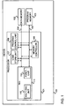
- Fig. 1 is a high level block diagram of an exemplary device according to embodiments of the present invention.
- Fig. 2 is a block diagram of an exemplary multi-MAC configuration according to embodiments of the present invention.
- Fig. 3 is a block diagram of an exemplary multi-MAC configuration according to embodiments of the present invention.
- Fig. 4 is a block diagram of an exemplary multi-MAC configuration according to embodiments of the present invention.
- Fig. 5 is flowchart of a method for scheduling MAC operations according to demonstrative embodiments of the present invention.
- the terms “plurality” and “a plurality” as used herein may include, for example, “multiple” or “two or more”.
- the terms “plurality” or “a plurality” may be used throughout the specification to describe two or more components, devices, elements, units, parameters, or the like.
- Embodiments of the invention may be used in signal processing in a variety of fields such as audio and speech signal processing, sonar and radar signal processing, sensor array processing, spectral estimation, statistical signal processing, digital image processing, signal processing for communications, biomedical signal processing, seismic data processing and the like.
- Embodiments of the invention may be implemented in digital signal processors (DSP's), for example in finite impulse response (FIR) filtering and in hardware accelerators.
- DSP's digital signal processors
- FIR finite impulse response
- some embodiments of the invention are described with respect to FIR filters, however, the invention is not limited to FIR filters and is applicable to any multi-multiply and accumulate (multi-MAC) architectures.
- Embodiments of the invention may include a chain of two or more multiply accumulators, each comprises a multiplier and an adder.
- the multiply accumulators may be arranged such that an output result of a first multiply accumulator of the chain may be delivered as an input to an adder of a second subsequent multiply accumulator of the chain and an output result of a last multiply accumulator of the chain may be delivered as an input to an adder of the first multiply accumulator of the chain.
- An exemplary device 100 may comprise a processor 101, a data memory unit 102 and a program memory unit 103.
- Device 100 may be a computer device, cellular device, a consumer electronics device or any other digital device.
- Processor 101 may be a digital signal processor (DSP), an application-specific integrated circuit (ASIC), a field-programmable gate array (FPGA) or may be implemented in any other hardware, software or a combination of hardware and software.
- DSP digital signal processor
- ASIC application-specific integrated circuit
- FPGA field-programmable gate array
- Processor 101 may be coupled to data memory unit 102 via a data memory bus 104 and to program memory unit 103 via a program memory bus 105.
- Data memory 102 and program memory 103 may be implemented as two separate memories or integrated within a single memory unit.
- Processor 101 may include a program control unit 108, a load/store unit 107, an arithmetic logic unit (ALU) 111 and a memory controller 109.
- Memory controller 109 may include a data memory controller (not shown) coupled to a data memory bus 104, and a program memory controller (not shown) coupled to a program memory bus 105.
- Load/store unit 107 may perform load and store operations from/to data memory unit 102.
- Program control unit 108 may retrieve, decode and dispatch machine language instructions from program memory unit 103 and may be responsible, in general, to the program flow.
- ALU 111 may include a multi multiply-accumulate (MAC) unit or multi multiply-accumulator 110 comprising two or more multiply-accumulate (MAC) units or structures and an arithmetic logic or functional unit 112.
- Functional unit 112 may perform one or more functionalities including add functions, subtract functions, bit manipulation, arithmetic logic and/or other general operations and any combination thereof.
- Multi MAC unit 110 may maximize the performance of the processor by using a plurality of MAC units simultaneously.
- Multi MAC unit 110 may be configured to enable scheduling MAC operations on multiple MAC units with low power dissipation.
- device 100 may further include other blocks, modules, operations and units which may perform or may take part in performing processing functions or operations.
- processor 101 includes program control unit 108, load/store unit 107, ALU 111, and memory controller 109, however, it should be understood to a person skilled in art that the invention is not limited in this respect and according to embodiments of the present invention any number and any kind of blocks, units and/or modules may be included in processor 101 and in device 100.
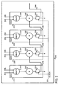
- FIG. 2 is a block diagram of an exemplary multi-MAC unit according to demonstrative embodiments of the invention.
- a multi-MAC unit such as multi MAC unit 200 may be part of a processor, such as processor 101 of Fig. 1 .
- Multi-MAC unit 200 may include a plurality of MAC units or structures, for example, MAC unit 210, MAC unit 220, MAC unit 230 and MAC unit 240.
- MAC unit 210 MAC unit 210
- MAC unit 220 MAC unit 230
- MAC unit 240 a plurality of MAC units or structures
- four MAC units are shown, it should be understood to a person skilled in art that the invention is not limited in this respect and according to embodiments of the present invention two or more MAC units may be used.
- each of the MAC units may include a multiplier, an adder and a memory element or unit.
- MAC unit 210 may include a multiplier 211, an adder 212 and a memory unit or element 213;
- MAC unit 220 may include a multiplier 221, an adder 222 and a memory element 223;
- MAC unit 230 may include a multiplier 231, an adder 232 and a memory element 233;
- MAC unit 240 may include a multiplier 241, an adder 242 and a memory element 243.
- Memory elements 213, 223, 233 and 243 may be clocked memory elements operated by a clock signal 201 and each memory element may store values, received from its respective adder, for a predetermined period determined by the clock signal.
- Each of the MAC units 210, 220, 230 and 240 may include two input signals to receive input operands.
- the input operands may be received, for example, from data memory 102 via load/store unit 107 of Fig. 1 .
- multiplier 211 of MAC unit 210 may receive a coefficient value via an input signal 214 and a data value via an input signal 215
- multiplier 221 of MAC unit 220 may receive a coefficient value via an input signal 224 and a data value via an input signal 225
- multiplier 231 of MAC unit 230 may receive a coefficient value via an input signal 234 and a data value via an input signal 235
- multiplier 241 of MAC unit 240 may receive a coefficient value via an input signal 244 and a data value via an input signal 245.
- multi-MAC unit 200 may be used for FIR filtering.
- the MAC unit may receive a coefficient value and a data value of the input signal as the input operands and may perform a single MAC operation on every clock cycle.
- the coefficient value c[i] is multiplied by the data value x[n-i] and the result is accumulated on a single accumulator as y[n] output signal.
- the coefficient c[i+1] is multiplied by the data value x[n-i-1] and the result is accumulated to the same y[n] output.
- the four parallel operations may be scheduled on four available MAC units, such as units 210-240, in an efficient manner that may reduce power dissipation.
- Relatively low power dissipation may be achieved by using for each MAC unit, a single coefficient value as an input operand to the multiplier for all the cycles required to calculate the output.
- Tables 1 and 2 show a schedule for four parallel MAC units that use the same coefficient input for eight cycles while the data multiplicand input is replaced in every cycle by the next data index. During these eight cycles, eleven different output signals are being handled by the four MAC units (from y[n+k-7] to y[n+k+3]).
- cycle 1 may include the following operations: (1) the coefficient c[1] received on input node 214 of multiplier 211 of MAC unit 210 is multiplied by the multiplicand x[n] and accumulated to the output signal y[n+1] on adder or accumulator 212 of MAC unit 210; (2) the coefficient c[2] received on input node 224 of multiplier 221 of MAC unit 220 is multiplied by the multiplicand x[n] and accumulated to the output signal y[n+2] on adder or accumulator 222 of MAC unit 220; (3) the coefficient c[3] received on input node 234 of multiplier 231 of MAC unit 230 is multiplied by the multiplicand x[n] and accumulated to the output signal y[n+3] on adder or accumulator 232 of MAC unit 230; and (4) the coefficient c[1] received on input node 214 of multiplier 211 of MAC unit 210 is multiplied by the multiplicand
- each of MAC units 210, 220, 230 and 240 may receive the same coefficient input in all the cycles, namely, the multipliers of MAC units 210, 220, 230 and 240 may receive coefficient, e.g., of a finite impulse response filter, that may be constant or unchanged for a predetermined time duration .
- the same coefficient value, c[k] may be received on input signal 214 of multiplier 211 of MAC unit 210 for all the cycles, designate k to k+7, as shown in column 2 of Table 1.
- the coefficient c[k+1] may be received on input node 224 of multiplier 221 of MAC unit 220 for the eight cycles, as shown in column 5 of Table 1; the coefficient c[k+2] may be received on input 234 of multiplier 231 of MAC unit 230 for all the cycles, as shown in column 2 of Table 2 and the coefficient c[k+3] may be received on input 244 of multiplier 241 of MAC unit 240 for the eight cycles, as shown in column 5 of Table 2.
- the number of MAC units may be smaller than the number of coefficients used to calculate each output signal y[n].
- each output signal y[n] may use eight c[i] coefficients. Accordingly, after completing the accumulation based on the first four coefficients for each output signal, the accumulation may continue for each eleven output signals for the next set of coefficients c[5] to c[8].
- MAC unit 210 may receive the coefficient c[5] for the next cycles
- MAC unit 220 may receive the coefficient c[6] for the next cycles
- MAC unit 230 may receive the coefficient c[7] for the next cycles
- MAC unit 240 may receive the coefficient c[8] for the next cycles.
- the data multiplicand input in every cycle may be replaced by the next data index.
- data x[n] is replaced by data x[n-1]
- data x[n-m] is replaced by data x[n-m-1].
- cycle 2 may include the following operations: (1) the coefficient c[1] received on input signal 214 of multiplier 211 of MAC unit 210 is multiplied by the multiplicand x[n-1] and accumulated to the output signal y[n] on adder or accumulator 212 of MAC unit 210; (2) the coefficient c[2] received on input signal 224 of multiplier 221 of MAC unit 220 is multiplied by the multiplicand x[n-1] and accumulated to the output signal y[n+1] on adder 222 of MAC unit 220; (3) the coefficient c[3] received on input signal 234 of multiplier 231 of MAC unit 230 is multiplied by the multiplicand x[n-1] and accumulated to the output signal y[n+2] on adder 232 of MAC unit 230; and (4) the coefficient c[4] received on input signal 244 of multiplier 241 of MAC unit 240 is multiplied by the multiplicand x[n-1] and accumulated
- the output result of each multiplication may be accumulated into a different accumulator or adder 212, 222, 232 or 242, where for each cycle another MAC unit may be used. From the last MAC unit, the result may be shifted out of multi-MAC unit 200 to be revisited for the accumulation of additional coefficients at a later stage of the schedule.
- This may be implemented by shifting the output result of an accumulator to an adjacent MAC unit for the following cycle.
- an output result in cycle k of adder 212 of MAC unit 210 may be transferred, shifted or mapped to adder 222 of MAC unit 220 via memory element 213 and output line 216 for the next cycle.
- accumulator 212 of MAC unit 210 may hold output signal y[n+k] at cycle k while accumulator 222 of MAC unit 220 may hold output signal y[n+k] at the next cycle k+1.
- the output result in cycle k+1 of accumulator 222 of MAC unit 220 may be transferred, shifted or mapped via memory element 223 and output line 226 to adder or accumulator 232 of MAC unit 230 for the next cycle.
- accumulator or adder 232 of MAC unit 230 may hold output signal y[n+k] at cycle k+2.
- the output result in cycle k+2 of accumulator 232 of MAC unit 230 may be transferred, shifted or mapped via memory element 233 and signal line 236 to adder 242 of MAC unit 240 for the next cycle.
- accumulator or adder 242 of MAC unit 240 may hold output signal y[n+k] at cycle k+3.
- the output result of accumulator 242 of MAC unit 240 for output signal y[n+k] may be shifted out via memory element 243 and signal line 246 as the final result of multi-MAC unit 200.
- the schedule implemented by Fig. 2 as described by Tables 1 and 2 may reduce power dissipation relative to using four "stand alone" MAC units, where each MAC unit accumulates a different output signal y[n] using the same coefficient c[i] as input to all four multipliers and a different data multiplicand x[n-i] through x[n+3-i].
- the coefficient c[i+1] may be used as an input to all four multipliers, while each multiplier may use the next data multiplicand x[n-i-1] through x[n+3-i-1].
- the schedule presented by Tables 1 and 2 may be most suitable when the number of available MAC units in the multi-MAC architecture does not exceed the number of coefficients in an output signal. but may be costly in terms of storing and re-loading each of the outputs if the number of coefficients is larger than the number of MAC units capable or processing simultaneously.
- the multi-MAC architecture may be generalized to any number of MAC units. If the number of MAC units is P, the output signal y[n] is operated P times before being shifted out. When the number of MAC units is greater than or equals the number of i coefficients, the schedule presented by Tables 1-2 may be an efficient optimal schedule in terms of both power dissipation and bandwidth. However, if the number of coefficients used to calculate an output signal i is larger than the number of MAC units P, then the partial output result of each output signal y[n] would need to be re-loaded back into the multi-MAC unit. The storing and re-loading operation of the partial output signal results may reduce, in certain conditions, the efficiency in terms of storage, bandwidth and power dissipation.
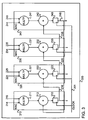
- FIG. 3 is block diagram of an exemplary multi-MAC unit according to some embodiments of the present invention.
- a multi-MAC unit such as multi-MAC unit may be part of a processor, such as processor 101 of Fig. 1 .
- Multi-MAC unit 300 may include a plurality of MAC units or structures, for example, MAC unit 310, MAC unit 320, MAC unit 330 and MAC unit 340. Each multi-MAC unit 310-340 may include a respective multiplier, adder and accumulator.
- Multi-MAC unit 300 is similar to multi-MAC unit 200 of Fig. 2 and similar elements are referenced with similar numerals. Although in the exemplary illustration of Fig. 3 , four MAC units are shown, it should be understood to a person skilled in art that the invention is not limited in this respect and according to embodiments of the present invention two or more MAC units may be used.
- memory element 243 of multi-MAC unit 340 may be coupled to adder 212 of multi-MAC unit 310 via a signal line 246.
- the architecture of multi-MAC unit 300 may enable the use of the schedule presented by Tables 3 and 4. Such a schedule may be suitable when the number of coefficients used to calculate the output signal is greater than the number of MAC structures in the multi-MAC unit.
- the schedule that may be implemented by multi-MAC mit 300 having four MAC units.
- Each MAC unit may receive as input the same coefficient operand for four cycles. Then, the coefficient indexed may be incremented by four.
- an architecture with P MAC units may maintain the coefficient index k of the coefficient inputs to every multiplier for P cycles before replacing the coefficient index with a new index k+P.
- Such a schedule may optimize the multiplier power dissipation while operating on the output y[n] for all i coefficients before storing the result.
- Tables 3 and 4 show a schedule for four parallel MAC units that use the same coefficient input for four cycles and then incrementing the coefficient index by four and using the new coefficient input for another for cycles. In this schedule the data multiplicand input is replaced in every cycle by the next data index. During these eight cycles, four output signals are being handled by the four MAC units (from y[n+k-3] to y[n+k]).
- the coefficient c[k] may be received on input 214 of multiplier 211 of MAC unit 310 for four cycles (from cycle k to cycle k+3) and after four cycles the coefficient c[k+4] may be received on the same input for another four cycles (from cycle k+4 to cycle k+7).
- the data multiplicand input may be replaced, in every cycle, by the next data index. For example, in MAC unit 310 after cycle k, data x[n] is replaced by data x[n-1], and after cycle k+m, data x[n-m] is replaced by data x[n-m-1].
- This may be implemented by shifting the output result of an accumulator to an adjacent MAC unit for the following cycle.
- the output of each multiplication may be accumulated into a different accumulator on each cycle.
- the output result of each multiplication may be accumulated into a different accumulator 212, 222, 232 or 242, where for each cycle another MAC unit may be used.
- the result may be transferred from the last MAC unit in the chain 240 to the first MAC unit of the chain 210.
- This may be implemented by shifting each of the accumulator outputs to the adjacent MAC unit for the following cycle.
- the output of the last MAC unit may be shifted back to the adder of the first MAC unit.
- Output 216 of adder 212 of MAC unit 310 may be transferred to adder 222 of MAC unit 320, output 226 from adder 222 of MAC unit 320 may be transferred to adder 232 of MAC unit 330, output 236 from adder 232 of MAC unit 330 may be transferred to adder 242 of MAC unit 340 and output 246 may be shifted back as an input to adder 212 of MAC unit 310.
- an output result in cycle k of accumulator 212 of MAC unit 310 may be transferred, shifted or mapped via signal line 216 to adder 222 of MAC unit 320 for the next cycle.
- accumulator 212 of MAC unit 310 may hold output signal y[n+k] at cycle k while accumulator 222 of MAC unit 320 may hold output signal y[n+k] at the next cycle k+1.
- the output result in cycle k+1 of accumulator 222 of MAC unit 320 may be transferred, shifted or mapped via signal line 226 to adder 232 of MAC unit 330 for the next cycle.
- accumulator 232 of MAC unit 330 may hold output signal y[n+k] at cycle k+2. Further, the output result in cycle k+2 of accumulator 232 of MAC unit 330 may be transferred, shifted or mapped via signal line 236 to adder 242 of MAC unit 340 for the next cycle. As shown by Table 4, accumulator 242 of MAC unit 340 may hold output signal y[n+k] at cycle k+3. The output result in cycle k+3 of accumulator 242 of MAC unit 340 for output signal y[n+k] may be shifted back to accumulator or adder 212 of MAC unit 310 via signal line 246.
- the schedule continues for another four cycles and the final output result of multi-MAC unit for the output signal y[n+k] includes all the multiplications for all 8 coefficients.
- each output y[n] of an adder is operated on four times, accumulating the results of four multiplications of the four multipliers, before being shifted back to the first adder 212.
- this architecture may be generalized to architecture with P MAC units, where each output may be operated on P times before being shifted back.
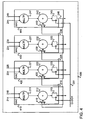
- FIG. 4 is a block diagram of an exemplary multi-MAC unit according to embodiments of the present invention.
- a multi-MAC unit, for example 400 may be implemented, for example as multi-MAC unit 110 of Fig. 1 .
- the architecture of multi-MAC unit 400 may enable the implementation of two or more schedules.
- Multi-MAC unit 400 may include a plurality of MAC units or MAC structures, for example, MAC unit 410, MAC unit 420, MAC unit 430 and MAC unit 440. Although in the exemplary illustration of Fig. 4 , four MAC units are shown, it should be understood to a person skilled in art that the invention is not limited in this respect and according to embodiments of the present invention two or more MAC units may be used.
- Each of MAC units 410-440 may include a multiplier, an adder and a memory element, similarly to MAC units 200 and 300, and further a multiplexer.
- the output of an accumulator may be shifted to another MAC unit to be accumulated into a different accumulator on each cycle or may be accumulated into the same adder.
- a selection may be made regarding whether to use the output of the adder as an input to the same adder or to shift the output of the adder as an input to the adder of the adjacent MAC unit.
- Such logic may be implemented by multiplexers 419, 429, 439 and 449 shown by Fig. 4 .
- Multiplexer 429 may select between the output of adder 212 and the output of adder 222 and may transfer one of the outputs to the input of adder 222.
- Multiplexer 439 may select between the output of adder 222 and the output of adder 232 and may transfer one of the outputs to the input of adder 232.
- Multiplexer 449 may select between the output of adder 232 and the output of adder 242 and may transfer one of the outputs to the input of adder 242.
- Multiplexer 419 may select between the output of adder 212 and the output of adder 242 and may transfer one of the outputs to the input of adder 212.
- FIG. 4 may be generalized to an architecture with any number MAC units.
- An embodiment of the invention having an architecture with two MAC units, namely a first and a second MAC units may include a first multiplexer to select either the output of the first adder or the output of the second adder as an input to the first adder and a second multiplexer to select either the output of the second adder or the output of the first adder as an input to the second adder.
- Fig. 5 is a flowchart of a method for scheduling MAC operations on multiple MAC units according to embodiments of the present invention. Operations of the method may be implemented by, for example, multi-MAC unit 110 of Fig. 1 , multi-MAC unit 200 of Fig. 2 , multi-MAC unit 300 of Fig. 3 and/or by any other suitable units, devices, and/or systems.
- the method may include receiving operands by each multiply accumulator of a chain of two or more multiply accumulators or MAC units.
- Each MAC unit may include at least a multiplier and an adder.
- a two-MAC unit implementation may include a first MAC unit "A” and a second MAC unit “B”.
- MAC unit "A” may include a first multiplier “A” and a first adder “A”
- MAC unit “B” may include a second multiplier "B” and a second adder "B”.
- the method may include multiplying the received operands by the multipliers of each of the MAC units.
- the method may include multiplying two operands by the first multiplier "A" and multiplying two other operands by the second multiplier "B".
- the multiplications may be performed simultaneously, for example, the multiplying process may be synchronized by a clocked signal.
- one of the two operands multiplied by the first multiplier is constant for a predetermined duration, e.g., for a predetermined clock cycles
- one of the two operands multiplied by the second multiplier is constant for a predetermined duration, e.g., for a predetermined clock cycles.
- the method may include adding by the second adder "B” a product of the second multiplier "B” to the output of the first adder "A".
- the output of the first adder “A” may be identical to the product of the first multiplier "A", if the product of the first multiplier "A” is the only input to the first adder "A", as presented for example, by Fig. 2 .
- the output of the first adder “A” may be different from the product of the first multiplier "A” since adder "A” may receive another input, for example, a stored result, e.g., output from the second adder "B” as presented, for example, by Fig. 3 and further indicated at box 530.
- Each of the adding results of adder "A" and adder “B” may be transferred and stored in a dedicated clocked memory element, for example, a D-flip flop element.
- a dedicated clocked memory element for example, a D-flip flop element.
- the sum of the product of the second multiplier "B” and the output of the first adder "A" of the first MAC unit may be saved for a predetermined duration, e.g., for a clock cycle, in a first memory element coupled to the first adder "A".
- the method may optionally include adding the output of the second adder "B” to the product of the first multiplier "A” by the first adder "A". It should be understood to a person skilled in the art the accumulated output result of the second adder “B” is being added to the result of the first multiplier "A” in a following clock cycle, i.e., the accumulated output result of the second adder "B” is being added the result of multiplying two new operands by multiplier "A".
- a chain of MAC units may include two or more MAC units.
- each adder of each of the MAC units may transfer its output to the adder of the consecutive, subsequent or adjacent MAC unit while the first adder of the first MAC unit may receive the output of the last adder and may add it to the product of the first multiplier of the first MAC in the following cycle, i.e., to the product of the next two operands multiplied by the first multiplier.
- Other operations or sets of operations may be used in accordance with embodiments of the invention.
- Embodiments of the invention may include an article such as a computer or processor readable medium, or a computer or processor storage medium, such as for example a memory, a disk drive, or a USB flash memory, encoding, including or storing instructions, e.g., computer-executable instructions, which when executed by a processor or controller, carry out methods disclosed herein.
- an article such as a computer or processor readable medium, or a computer or processor storage medium, such as for example a memory, a disk drive, or a USB flash memory, encoding, including or storing instructions, e.g., computer-executable instructions, which when executed by a processor or controller, carry out methods disclosed herein.
- Embodiments of the invention may include components such as, but not limited to, a plurality of central processing units (CPU) or any other suitable multi-purpose or specific processors or controllers, a plurality of input units, a plurality of output units, a plurality of memory units, and a plurality of storage units.
- Such system may additionally include other suitable hardware components and/or software components.
- such system may include or may be, for example, a personal computer, a desktop computer, a mobile computer, a laptop computer, a notebook computer, a terminal, a workstation, a server computer, a Personal Digital Assistant (PDA) device, a tablet computer, a network device, or any other suitable computing device.
- PDA Personal Digital Assistant
- an architecture with a minimum value of "P" equals two MAC units may include a first MAC unit may comprise a first multiplier and a first adder, wherein the first multiplier may receive and multiply two operands and a second MAC unit may comprise a second multiplier and a second adder, wherein the second multiplier may receive and multiply two operands and wherein the second adder may receive and add a product of the second multiplier to an output of the first adder.
- the first adder may optionally receive and add a product of the first multiplier to an output of the second adder (presented by Fig.
- the first adder may optionally receive and add a product of the first multiplier to a pre-stored output.
- Another embodiment may further include a third MAC unit which may comprise a third multiplier and a third adder, wherein the third multiplier may receive and multiply two operands and wherein the third adder may receive and add a product of the third multiplier to an output of the second adder.
- the first adder may optionally receive and add a product of the first multiplier to an output of the third adder (presented by Fig. 3 ).
- one of the two operands received by the first multiplier may be the same for a predetermined duration, e.g., for a predetermined number of clock cycles and one of the two operands received by the second multiplier may be the same for a predetermined duration, e.g., for a predetermined number of clock cycles.
- the first MAC unit may further comprise a first memory element to hold the output of the first adder for a predetermined duration, e.g., for a predetermined number of clock cycles
- the second MAC unit may comprise a second memory element to hold the output of the second adder for a predetermined duration, e.g., for a predetermined number of clock cycles.
Landscapes
- Engineering & Computer Science (AREA)
- Physics & Mathematics (AREA)
- General Physics & Mathematics (AREA)
- Theoretical Computer Science (AREA)
- Computational Mathematics (AREA)
- Computing Systems (AREA)
- Mathematical Analysis (AREA)
- Mathematical Optimization (AREA)
- Pure & Applied Mathematics (AREA)
- General Engineering & Computer Science (AREA)
- Complex Calculations (AREA)
Applications Claiming Priority (1)
| Application Number | Priority Date | Filing Date | Title |
|---|---|---|---|
| US12/512,032 US8706791B2 (en) | 2009-07-30 | 2009-07-30 | Low power fir filter in multi-MAC architecture |
Publications (2)
| Publication Number | Publication Date |
|---|---|
| EP2280341A1 EP2280341A1 (en) | 2011-02-02 |
| EP2280341B1 true EP2280341B1 (en) | 2013-06-05 |
Family
ID=43216926
Family Applications (1)
| Application Number | Title | Priority Date | Filing Date |
|---|---|---|---|
| EP10170647.1A Active EP2280341B1 (en) | 2009-07-30 | 2010-07-23 | Low power FIR filter in multi-mac architecture |
Country Status (4)
| Country | Link |
|---|---|
| US (1) | US8706791B2 (enExample) |
| EP (1) | EP2280341B1 (enExample) |
| JP (1) | JP5544240B2 (enExample) |
| CA (1) | CA2711027C (enExample) |
Cited By (2)
| Publication number | Priority date | Publication date | Assignee | Title |
|---|---|---|---|---|
| WO2020046642A1 (en) * | 2018-08-31 | 2020-03-05 | Flex Logix Technologies, Inc. | Multiplier-accumulator circuit, logic tile architecture for multiply-accumulate and ic including logic tile array |
| US11768790B2 (en) | 2020-04-18 | 2023-09-26 | Flex Logix Technologies, Inc. | MAC processing pipelines, circuitry to control and configure same, and methods of operating same |
Families Citing this family (15)
| Publication number | Priority date | Publication date | Assignee | Title |
|---|---|---|---|---|
| JP7165018B2 (ja) * | 2018-10-03 | 2022-11-02 | キヤノン株式会社 | 情報処理装置、情報処理方法 |
| US11194585B2 (en) | 2019-03-25 | 2021-12-07 | Flex Logix Technologies, Inc. | Multiplier-accumulator circuitry having processing pipelines and methods of operating same |
| US11314504B2 (en) | 2019-04-09 | 2022-04-26 | Flex Logix Technologies, Inc. | Multiplier-accumulator processing pipelines and processing component, and methods of operating same |
| US11288076B2 (en) | 2019-09-13 | 2022-03-29 | Flex Logix Technologies, Inc. | IC including logic tile, having reconfigurable MAC pipeline, and reconfigurable memory |
| US11455368B2 (en) | 2019-10-02 | 2022-09-27 | Flex Logix Technologies, Inc. | MAC processing pipeline having conversion circuitry, and methods of operating same |
| US12015428B2 (en) | 2019-11-05 | 2024-06-18 | Flex Logix Technologies, Inc. | MAC processing pipeline using filter weights having enhanced dynamic range, and methods of operating same |
| US11693625B2 (en) | 2019-12-04 | 2023-07-04 | Flex Logix Technologies, Inc. | Logarithmic addition-accumulator circuitry, processing pipeline including same, and methods of operation |
| US11960856B1 (en) | 2020-01-15 | 2024-04-16 | Flex Logix Technologies, Inc. | Multiplier-accumulator processing pipeline using filter weights having gaussian floating point data format |
| US12282748B1 (en) | 2020-05-26 | 2025-04-22 | Analog Devices, Inc. | Coarse floating point accumulator circuit, and MAC processing pipelines including same |
| US11604645B2 (en) | 2020-07-22 | 2023-03-14 | Flex Logix Technologies, Inc. | MAC processing pipelines having programmable granularity, and methods of operating same |
| US12282749B2 (en) | 2020-08-20 | 2025-04-22 | Analog Devices, Inc. | Configurable MAC pipelines for finite-impulse-response filtering, and methods of operating same |
| US12455723B2 (en) | 2021-02-02 | 2025-10-28 | Analog Devices, Inc. | MAC processing pipeline having activation circuitry, and methods of operating same |
| US12461713B2 (en) | 2021-03-03 | 2025-11-04 | Analog Devices, Inc. | MAC processing pipelines, circuitry to configure same, and methods of operating same |
| US12430100B2 (en) * | 2021-06-01 | 2025-09-30 | Ceremorphic, Inc. | Analog multiplier accumulator with unit element gain balancing |
| CN120045162B (zh) * | 2025-04-25 | 2025-09-16 | 北京凯芯微科技有限公司 | 一种抗混叠降采样电路、电路模组、芯片和信号处理装置 |
Family Cites Families (7)
| Publication number | Priority date | Publication date | Assignee | Title |
|---|---|---|---|---|
| JP3693367B2 (ja) * | 1994-07-28 | 2005-09-07 | 富士通株式会社 | 積和演算器 |
| US5931892A (en) * | 1996-12-20 | 1999-08-03 | Compaq Computer Corporation | Enhanced adaptive filtering technique |
| US5862063A (en) | 1996-12-20 | 1999-01-19 | Compaq Computer Corporation | Enhanced wavetable processing technique on a vector processor having operand routing and slot selectable operations |
| JPH1196136A (ja) | 1997-09-24 | 1999-04-09 | Fujitsu Ltd | 積和演算モジュール |
| JP2002073586A (ja) | 2000-08-28 | 2002-03-12 | Matsushita Electric Ind Co Ltd | 演算処理装置 |
| US6978287B1 (en) * | 2001-04-04 | 2005-12-20 | Altera Corporation | DSP processor architecture with write datapath word conditioning and analysis |
| US7570704B2 (en) | 2005-11-30 | 2009-08-04 | Intel Corporation | Transmitter architecture for high-speed communications |
-
2009
- 2009-07-30 US US12/512,032 patent/US8706791B2/en active Active
-
2010
- 2010-07-23 EP EP10170647.1A patent/EP2280341B1/en active Active
- 2010-07-29 CA CA2711027A patent/CA2711027C/en active Active
- 2010-07-30 JP JP2010173110A patent/JP5544240B2/ja active Active
Cited By (2)
| Publication number | Priority date | Publication date | Assignee | Title |
|---|---|---|---|---|
| WO2020046642A1 (en) * | 2018-08-31 | 2020-03-05 | Flex Logix Technologies, Inc. | Multiplier-accumulator circuit, logic tile architecture for multiply-accumulate and ic including logic tile array |
| US11768790B2 (en) | 2020-04-18 | 2023-09-26 | Flex Logix Technologies, Inc. | MAC processing pipelines, circuitry to control and configure same, and methods of operating same |
Also Published As
| Publication number | Publication date |
|---|---|
| CA2711027C (en) | 2016-05-10 |
| US20110029589A1 (en) | 2011-02-03 |
| US8706791B2 (en) | 2014-04-22 |
| CA2711027A1 (en) | 2011-01-30 |
| JP5544240B2 (ja) | 2014-07-09 |
| EP2280341A1 (en) | 2011-02-02 |
| JP2011034566A (ja) | 2011-02-17 |
Similar Documents
| Publication | Publication Date | Title |
|---|---|---|
| EP2280341B1 (en) | Low power FIR filter in multi-mac architecture | |
| CN115039067B (zh) | 包括具有高效预规格化和扩展动态范围的熔合乘法累加的脉动阵列 | |
| CN114868108B (zh) | 组合多个整数和浮点数据类型的脉动阵列部件 | |
| US20230064381A1 (en) | Memory-Size- and Bandwidth-Efficient Method for Feeding Systolic Array Matrix Multipliers | |
| US12020151B2 (en) | Neural network processor | |
| US10817260B1 (en) | Reducing dynamic power consumption in arrays | |
| US5880981A (en) | Method and apparatus for reducing the power consumption in a programmable digital signal processor | |
| US9613232B1 (en) | Digital signal processing blocks with embedded arithmetic circuits | |
| US20140365548A1 (en) | Vector matrix product accelerator for microprocessor integration | |
| Mohanty et al. | A high-performance VLSI architecture for reconfigurable FIR using distributed arithmetic | |
| CN117813585B (zh) | 具有高效输入缩减和扩展阵列性能的脉动阵列 | |
| EP3796190A1 (en) | Memory device and method | |
| CN110109646B (zh) | 数据处理方法、装置和乘加器及存储介质 | |
| US9632752B2 (en) | System and method for implementing a multiplication | |
| US6675286B1 (en) | Multimedia instruction set for wide data paths | |
| US20230075348A1 (en) | Computing device and method using multiplier-accumulator | |
| US9082476B2 (en) | Data accessing method to boost performance of FIR operation on balanced throughput data-path architecture | |
| CN114341796B (zh) | 带符号多字乘法器 | |
| US20220156344A1 (en) | Systolic array cells with output post-processing | |
| KR20080050226A (ko) | 모듈러 곱셈 장치 및 설계 방법 | |
| JP5262248B2 (ja) | 積和演算回路 | |
| Das et al. | Hardware implementation of parallel FIR filter using modified distributed arithmetic | |
| Raj et al. | A paradigm of distributed arithmetic (DA) approaches for digital FIR filter | |
| US20210034956A1 (en) | Minimum memory digital convolver | |
| Ou et al. | An energy-efficient, high-precision SFP LPFIR filter engine for digital hearing aids |
Legal Events
| Date | Code | Title | Description |
|---|---|---|---|
| PUAI | Public reference made under article 153(3) epc to a published international application that has entered the european phase |
Free format text: ORIGINAL CODE: 0009012 |
|
| AK | Designated contracting states |
Kind code of ref document: A1 Designated state(s): AL AT BE BG CH CY CZ DE DK EE ES FI FR GB GR HR HU IE IS IT LI LT LU LV MC MK MT NL NO PL PT RO SE SI SK SM TR |
|
| AX | Request for extension of the european patent |
Extension state: BA ME RS |
|
| 17P | Request for examination filed |
Effective date: 20110722 |
|
| GRAP | Despatch of communication of intention to grant a patent |
Free format text: ORIGINAL CODE: EPIDOSNIGR1 |
|
| RIC1 | Information provided on ipc code assigned before grant |
Ipc: G06F 7/544 20060101AFI20121205BHEP |
|
| RAP1 | Party data changed (applicant data changed or rights of an application transferred) |
Owner name: CEVA D.S.P. LTD. |
|
| GRAS | Grant fee paid |
Free format text: ORIGINAL CODE: EPIDOSNIGR3 |
|
| GRAA | (expected) grant |
Free format text: ORIGINAL CODE: 0009210 |
|
| AK | Designated contracting states |
Kind code of ref document: B1 Designated state(s): AL AT BE BG CH CY CZ DE DK EE ES FI FR GB GR HR HU IE IS IT LI LT LU LV MC MK MT NL NO PL PT RO SE SI SK SM TR |
|
| REG | Reference to a national code |
Ref country code: GB Ref legal event code: FG4D |
|
| REG | Reference to a national code |
Ref country code: CH Ref legal event code: EP |
|
| REG | Reference to a national code |
Ref country code: AT Ref legal event code: REF Ref document number: 616010 Country of ref document: AT Kind code of ref document: T Effective date: 20130615 |
|
| REG | Reference to a national code |
Ref country code: IE Ref legal event code: FG4D |
|
| REG | Reference to a national code |
Ref country code: DE Ref legal event code: R096 Ref document number: 602010007508 Country of ref document: DE Effective date: 20130801 |
|
| REG | Reference to a national code |
Ref country code: AT Ref legal event code: MK05 Ref document number: 616010 Country of ref document: AT Kind code of ref document: T Effective date: 20130605 |
|
| PG25 | Lapsed in a contracting state [announced via postgrant information from national office to epo] |
Ref country code: SI Free format text: LAPSE BECAUSE OF FAILURE TO SUBMIT A TRANSLATION OF THE DESCRIPTION OR TO PAY THE FEE WITHIN THE PRESCRIBED TIME-LIMIT Effective date: 20130605 Ref country code: FI Free format text: LAPSE BECAUSE OF FAILURE TO SUBMIT A TRANSLATION OF THE DESCRIPTION OR TO PAY THE FEE WITHIN THE PRESCRIBED TIME-LIMIT Effective date: 20130605 Ref country code: NO Free format text: LAPSE BECAUSE OF FAILURE TO SUBMIT A TRANSLATION OF THE DESCRIPTION OR TO PAY THE FEE WITHIN THE PRESCRIBED TIME-LIMIT Effective date: 20130905 Ref country code: ES Free format text: LAPSE BECAUSE OF FAILURE TO SUBMIT A TRANSLATION OF THE DESCRIPTION OR TO PAY THE FEE WITHIN THE PRESCRIBED TIME-LIMIT Effective date: 20130916 Ref country code: GR Free format text: LAPSE BECAUSE OF FAILURE TO SUBMIT A TRANSLATION OF THE DESCRIPTION OR TO PAY THE FEE WITHIN THE PRESCRIBED TIME-LIMIT Effective date: 20130906 Ref country code: SE Free format text: LAPSE BECAUSE OF FAILURE TO SUBMIT A TRANSLATION OF THE DESCRIPTION OR TO PAY THE FEE WITHIN THE PRESCRIBED TIME-LIMIT Effective date: 20130605 Ref country code: AT Free format text: LAPSE BECAUSE OF FAILURE TO SUBMIT A TRANSLATION OF THE DESCRIPTION OR TO PAY THE FEE WITHIN THE PRESCRIBED TIME-LIMIT Effective date: 20130605 Ref country code: LT Free format text: LAPSE BECAUSE OF FAILURE TO SUBMIT A TRANSLATION OF THE DESCRIPTION OR TO PAY THE FEE WITHIN THE PRESCRIBED TIME-LIMIT Effective date: 20130605 |
|
| REG | Reference to a national code |
Ref country code: NL Ref legal event code: VDEP Effective date: 20130605 |
|
| REG | Reference to a national code |
Ref country code: LT Ref legal event code: MG4D |
|
| PG25 | Lapsed in a contracting state [announced via postgrant information from national office to epo] |
Ref country code: BG Free format text: LAPSE BECAUSE OF FAILURE TO SUBMIT A TRANSLATION OF THE DESCRIPTION OR TO PAY THE FEE WITHIN THE PRESCRIBED TIME-LIMIT Effective date: 20130905 Ref country code: HR Free format text: LAPSE BECAUSE OF FAILURE TO SUBMIT A TRANSLATION OF THE DESCRIPTION OR TO PAY THE FEE WITHIN THE PRESCRIBED TIME-LIMIT Effective date: 20130605 |
|
| PG25 | Lapsed in a contracting state [announced via postgrant information from national office to epo] |
Ref country code: LV Free format text: LAPSE BECAUSE OF FAILURE TO SUBMIT A TRANSLATION OF THE DESCRIPTION OR TO PAY THE FEE WITHIN THE PRESCRIBED TIME-LIMIT Effective date: 20130605 |
|
| PG25 | Lapsed in a contracting state [announced via postgrant information from national office to epo] |
Ref country code: BE Free format text: LAPSE BECAUSE OF FAILURE TO SUBMIT A TRANSLATION OF THE DESCRIPTION OR TO PAY THE FEE WITHIN THE PRESCRIBED TIME-LIMIT Effective date: 20130605 Ref country code: EE Free format text: LAPSE BECAUSE OF FAILURE TO SUBMIT A TRANSLATION OF THE DESCRIPTION OR TO PAY THE FEE WITHIN THE PRESCRIBED TIME-LIMIT Effective date: 20130605 Ref country code: IS Free format text: LAPSE BECAUSE OF FAILURE TO SUBMIT A TRANSLATION OF THE DESCRIPTION OR TO PAY THE FEE WITHIN THE PRESCRIBED TIME-LIMIT Effective date: 20131005 Ref country code: PT Free format text: LAPSE BECAUSE OF FAILURE TO SUBMIT A TRANSLATION OF THE DESCRIPTION OR TO PAY THE FEE WITHIN THE PRESCRIBED TIME-LIMIT Effective date: 20131007 Ref country code: SK Free format text: LAPSE BECAUSE OF FAILURE TO SUBMIT A TRANSLATION OF THE DESCRIPTION OR TO PAY THE FEE WITHIN THE PRESCRIBED TIME-LIMIT Effective date: 20130605 Ref country code: CZ Free format text: LAPSE BECAUSE OF FAILURE TO SUBMIT A TRANSLATION OF THE DESCRIPTION OR TO PAY THE FEE WITHIN THE PRESCRIBED TIME-LIMIT Effective date: 20130605 |
|
| PG25 | Lapsed in a contracting state [announced via postgrant information from national office to epo] |
Ref country code: RO Free format text: LAPSE BECAUSE OF FAILURE TO SUBMIT A TRANSLATION OF THE DESCRIPTION OR TO PAY THE FEE WITHIN THE PRESCRIBED TIME-LIMIT Effective date: 20130605 Ref country code: NL Free format text: LAPSE BECAUSE OF FAILURE TO SUBMIT A TRANSLATION OF THE DESCRIPTION OR TO PAY THE FEE WITHIN THE PRESCRIBED TIME-LIMIT Effective date: 20130605 Ref country code: PL Free format text: LAPSE BECAUSE OF FAILURE TO SUBMIT A TRANSLATION OF THE DESCRIPTION OR TO PAY THE FEE WITHIN THE PRESCRIBED TIME-LIMIT Effective date: 20130605 |
|
| PG25 | Lapsed in a contracting state [announced via postgrant information from national office to epo] |
Ref country code: MC Free format text: LAPSE BECAUSE OF FAILURE TO SUBMIT A TRANSLATION OF THE DESCRIPTION OR TO PAY THE FEE WITHIN THE PRESCRIBED TIME-LIMIT Effective date: 20130605 |
|
| PLBE | No opposition filed within time limit |
Free format text: ORIGINAL CODE: 0009261 |
|
| STAA | Information on the status of an ep patent application or granted ep patent |
Free format text: STATUS: NO OPPOSITION FILED WITHIN TIME LIMIT |
|
| PG25 | Lapsed in a contracting state [announced via postgrant information from national office to epo] |
Ref country code: DK Free format text: LAPSE BECAUSE OF FAILURE TO SUBMIT A TRANSLATION OF THE DESCRIPTION OR TO PAY THE FEE WITHIN THE PRESCRIBED TIME-LIMIT Effective date: 20130605 |
|
| 26N | No opposition filed |
Effective date: 20140306 |
|
| PG25 | Lapsed in a contracting state [announced via postgrant information from national office to epo] |
Ref country code: IT Free format text: LAPSE BECAUSE OF FAILURE TO SUBMIT A TRANSLATION OF THE DESCRIPTION OR TO PAY THE FEE WITHIN THE PRESCRIBED TIME-LIMIT Effective date: 20130605 |
|
| REG | Reference to a national code |
Ref country code: DE Ref legal event code: R097 Ref document number: 602010007508 Country of ref document: DE Effective date: 20140306 |
|
| PG25 | Lapsed in a contracting state [announced via postgrant information from national office to epo] |
Ref country code: SM Free format text: LAPSE BECAUSE OF FAILURE TO SUBMIT A TRANSLATION OF THE DESCRIPTION OR TO PAY THE FEE WITHIN THE PRESCRIBED TIME-LIMIT Effective date: 20130605 |
|
| PG25 | Lapsed in a contracting state [announced via postgrant information from national office to epo] |
Ref country code: TR Free format text: LAPSE BECAUSE OF FAILURE TO SUBMIT A TRANSLATION OF THE DESCRIPTION OR TO PAY THE FEE WITHIN THE PRESCRIBED TIME-LIMIT Effective date: 20130605 Ref country code: CY Free format text: LAPSE BECAUSE OF FAILURE TO SUBMIT A TRANSLATION OF THE DESCRIPTION OR TO PAY THE FEE WITHIN THE PRESCRIBED TIME-LIMIT Effective date: 20130605 Ref country code: MT Free format text: LAPSE BECAUSE OF FAILURE TO SUBMIT A TRANSLATION OF THE DESCRIPTION OR TO PAY THE FEE WITHIN THE PRESCRIBED TIME-LIMIT Effective date: 20130605 |
|
| PG25 | Lapsed in a contracting state [announced via postgrant information from national office to epo] |
Ref country code: HU Free format text: LAPSE BECAUSE OF FAILURE TO SUBMIT A TRANSLATION OF THE DESCRIPTION OR TO PAY THE FEE WITHIN THE PRESCRIBED TIME-LIMIT; INVALID AB INITIO Effective date: 20100723 Ref country code: LU Free format text: LAPSE BECAUSE OF NON-PAYMENT OF DUE FEES Effective date: 20130723 Ref country code: MK Free format text: LAPSE BECAUSE OF FAILURE TO SUBMIT A TRANSLATION OF THE DESCRIPTION OR TO PAY THE FEE WITHIN THE PRESCRIBED TIME-LIMIT Effective date: 20130605 |
|
| REG | Reference to a national code |
Ref country code: FR Ref legal event code: PLFP Year of fee payment: 7 |
|
| REG | Reference to a national code |
Ref country code: FR Ref legal event code: PLFP Year of fee payment: 8 |
|
| REG | Reference to a national code |
Ref country code: FR Ref legal event code: PLFP Year of fee payment: 9 |
|
| PG25 | Lapsed in a contracting state [announced via postgrant information from national office to epo] |
Ref country code: AL Free format text: LAPSE BECAUSE OF FAILURE TO SUBMIT A TRANSLATION OF THE DESCRIPTION OR TO PAY THE FEE WITHIN THE PRESCRIBED TIME-LIMIT Effective date: 20130605 |
|
| PGFP | Annual fee paid to national office [announced via postgrant information from national office to epo] |
Ref country code: DE Payment date: 20250722 Year of fee payment: 16 |
|
| PGFP | Annual fee paid to national office [announced via postgrant information from national office to epo] |
Ref country code: GB Payment date: 20250722 Year of fee payment: 16 |
|
| PGFP | Annual fee paid to national office [announced via postgrant information from national office to epo] |
Ref country code: FR Payment date: 20250725 Year of fee payment: 16 |
|
| PGFP | Annual fee paid to national office [announced via postgrant information from national office to epo] |
Ref country code: CH Payment date: 20250801 Year of fee payment: 16 |
|
| PGFP | Annual fee paid to national office [announced via postgrant information from national office to epo] |
Ref country code: IE Payment date: 20250723 Year of fee payment: 16 |