EP2280171A1 - Reciprocating compressor - Google Patents
Reciprocating compressor Download PDFInfo
- Publication number
- EP2280171A1 EP2280171A1 EP09724940A EP09724940A EP2280171A1 EP 2280171 A1 EP2280171 A1 EP 2280171A1 EP 09724940 A EP09724940 A EP 09724940A EP 09724940 A EP09724940 A EP 09724940A EP 2280171 A1 EP2280171 A1 EP 2280171A1
- Authority
- EP
- European Patent Office
- Prior art keywords
- valve plate
- cylinder block
- opposing
- suction
- holes
- Prior art date
- Legal status (The legal status is an assumption and is not a legal conclusion. Google has not performed a legal analysis and makes no representation as to the accuracy of the status listed.)
- Withdrawn
Links
Images


Classifications
-
- F—MECHANICAL ENGINEERING; LIGHTING; HEATING; WEAPONS; BLASTING
- F04—POSITIVE - DISPLACEMENT MACHINES FOR LIQUIDS; PUMPS FOR LIQUIDS OR ELASTIC FLUIDS
- F04B—POSITIVE-DISPLACEMENT MACHINES FOR LIQUIDS; PUMPS
- F04B27/00—Multi-cylinder pumps specially adapted for elastic fluids and characterised by number or arrangement of cylinders
- F04B27/08—Multi-cylinder pumps specially adapted for elastic fluids and characterised by number or arrangement of cylinders having cylinders coaxial with, or parallel or inclined to, main shaft axis
- F04B27/10—Multi-cylinder pumps specially adapted for elastic fluids and characterised by number or arrangement of cylinders having cylinders coaxial with, or parallel or inclined to, main shaft axis having stationary cylinders
- F04B27/1009—Distribution members
-
- F—MECHANICAL ENGINEERING; LIGHTING; HEATING; WEAPONS; BLASTING
- F04—POSITIVE - DISPLACEMENT MACHINES FOR LIQUIDS; PUMPS FOR LIQUIDS OR ELASTIC FLUIDS
- F04B—POSITIVE-DISPLACEMENT MACHINES FOR LIQUIDS; PUMPS
- F04B39/00—Component parts, details, or accessories, of pumps or pumping systems specially adapted for elastic fluids, not otherwise provided for in, or of interest apart from, groups F04B25/00 - F04B37/00
- F04B39/10—Adaptations or arrangements of distribution members
- F04B39/1066—Valve plates
-
- F—MECHANICAL ENGINEERING; LIGHTING; HEATING; WEAPONS; BLASTING
- F04—POSITIVE - DISPLACEMENT MACHINES FOR LIQUIDS; PUMPS FOR LIQUIDS OR ELASTIC FLUIDS
- F04B—POSITIVE-DISPLACEMENT MACHINES FOR LIQUIDS; PUMPS
- F04B39/00—Component parts, details, or accessories, of pumps or pumping systems specially adapted for elastic fluids, not otherwise provided for in, or of interest apart from, groups F04B25/00 - F04B37/00
- F04B39/10—Adaptations or arrangements of distribution members
- F04B39/1073—Adaptations or arrangements of distribution members the members being reed valves
-
- Y—GENERAL TAGGING OF NEW TECHNOLOGICAL DEVELOPMENTS; GENERAL TAGGING OF CROSS-SECTIONAL TECHNOLOGIES SPANNING OVER SEVERAL SECTIONS OF THE IPC; TECHNICAL SUBJECTS COVERED BY FORMER USPC CROSS-REFERENCE ART COLLECTIONS [XRACs] AND DIGESTS
- Y10—TECHNICAL SUBJECTS COVERED BY FORMER USPC
- Y10T—TECHNICAL SUBJECTS COVERED BY FORMER US CLASSIFICATION
- Y10T137/00—Fluid handling
- Y10T137/7722—Line condition change responsive valves
- Y10T137/7837—Direct response valves [i.e., check valve type]
- Y10T137/7838—Plural
- Y10T137/7843—Integral resilient member forms plural valves
Definitions
- the present invention relates to a reciprocating compressor.
- Patent Document No.1 teaches a reciprocating compressor comprising a cylinder block provided with cylinder bores, pistons fitted in the cylinder bores, a front housing opposing one of the end faces of the cylinder block to cooperate with the cylinder block and thereby form a crank chamber accommodating a piston driving mechanism, a valve plate opposing the other one of the end faces of the cylinder block and provided with suction holes and discharge holes communicating with the cylinder bores, a rear housing provided with a suction chamber and a discharge chamber and opposing the other one of the end faces of the cylinder block with the valve plate inserted between them, strap-shaped suction valves fitted on the end face of the valve plate opposing the cylinder block to abut the valve plate, thereby opening and closing the suction holes at tip portions, discharge valves fitted on the end face of the valve plate opposing the rear housing to open and close the discharge holes, and through-bolts passed through the front housing, the crank chamber, the cylinder block, the valve plate and the rear housing to assemble them as a unitary
- the technology of the Patent Document No.1 is aimed at decreasing adhesion of lubrication oil existing between the suction valves and the valve plate, thereby decreasing the resistance force against the opening of the suction valves.
- the present invention takes a different viewpoint from that of the conventional technology in that delayed opening of the suction valves is prevented by decreasing the resistance force against the opening of the suction valves.
- An object of the present invention is to provide a technology for increasing force for promoting the opening of the suction valves to prevent delayed opening of suction valves.
- a reciprocating compressor comprising a cylinder block provided with cylinder bores, pistons fitted in the cylinder bores, a front housing opposing one of the end faces of the cylinder block to cooperate with the cylinder block and thereby form a crank chamber accommodating a piston driving mechanism, a valve plate opposing the other one of the end faces of the cylinder block and provided with suction holes and discharge holes communicating with the cylinder bores, a rear housing provided with a suction chamber and a discharge chamber and opposing the other one of the end faces of the cylinder block with the valve plate inserted between them, strap-shaped suction valves fitted on the end face of the valve plate opposing the cylinder block to abut the valve plate, thereby opening and closing the suction holes at tip portions, discharge valves fitted on the end face of the valve plate opposing the rear housing to open and close the discharge holes, and through-bolts passed through the front housing, the crank chamber, the cylinder block, the valve plate and the rear housing to assemble them as
- crank chamber pressure is applied to the surfaces of the suction valves abutting the valve plate through holes for accommodating the through-bolts and the grooves formed in the valve plate to force the suction valves in the direction of opening.
- the grooves extend beyond the portions opposing the roots of the suction valves to the portions near the suction holes.
- the area of the suction valves receiving the crank chamber pressure increases to increase the force for promoting the opening of the suction valves.
- a reciprocating compressor wherein force for promoting the opening of the suction valves is increased to prevent delayed opening of suction valves.
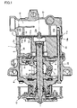
- a variable displacement swash plate compressor 1 comprises a circular-column-shaped cylinder block 2 provided with a plurality of cylinder bores 2a, a front housing 4 given a cylindrical shape closed at one end and opposing one of the end faces of the cylinder block 2 to cooperate with the cylinder block 2 and thereby form a crank chamber 3, a rotation shaft 5 disposed in the crank chamber 3, rotatably supported by the cylinder block 2 and the front housing 4, and extending out of the crank chamber 3 through the front housing 4 at one end, a rotor 6 disposed in the crank chamber 3 and fixed to the rotation shaft 5, a swash plate 8 disposed in the crank chamber 3, connected to the rotor 6 through a link member 7, engaging the rotation shaft 5 at a variable inclination, and rotated by the rotation shaft 5, pairs of shoes 9 disposed in the crank chamber 3 and slidably engaging the outer peripheral portion of the swash plate 8, pistons 10 fitted in the cylinder bores 2a and slidably engaging the outer peripheral portion of
- the rotation shaft 5, the rotor 6, the link member 7, the swash plate 8 and the shoes 9 constitute a piston driving mechanism.
- the cylinder bores 2a, the pistons 10, the suction holes 11a, the discharge holes 11b, the suction valves 13, the discharge valves 14 and pairs of shoes 9 are distanced from each other in the circumferential direction.
- the suction chamber 12a communicates with the evaporator of a car air conditioner through a suction port 16.
- the discharge chamber 12b communicates with the condenser of the car air conditioner through a discharge port.
- the evaporator, the condenser, the car air conditioner and the discharge port are not shown in Figure 1 .
- the rotation shaft 5 is directly connected to a car engine through a power transmission device 17 at one end protruding out of the crank chamber 3.
- the car engine is not shown in Figure 1 .
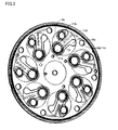
- the suction valves 13 are made by punching U-shaped holes 18a through a circular thin plate 18.
- the circular thin plate 18 is provided with holes 18b for accommodating the through-bolts 15, in addition to the U-shaped holes 18a.
- the valve plate 11 cooperates with the cylinder block 2 to clamp the circular thin plate 18, thereby making the circular thin plate 18 abut on the valve plate 11.
- the suction valves 13 are fitted on the valve plate 11.
- the U-shaped holes 18a oppose the discharge holes 11b formed in the valve plate 11 when the circular thin plate 18 is clamped by the valve plate 11 and the cylinder block 2 to abut on the valve plate 11.
- the valve plate 11 is provided with holes 11c for accommodating the through-bolts 15, in addition to the suction holes 11a and the discharge holes 11b.
- the valve plate 11 is provided with grooves 11d in the end face opposing the cylinder block 2 through the circular thin plate 18.
- the grooves 11d extend from the holes 11c to the portions abutting the suction valves 13 without interfering with the adjacent discharge holes 11b or opposing the U-shaped holes 18a of the circular thin plate 18 abutting the valve plate 11.
- the grooves 11d extend beyond the portions opposing the roots of the suction valves 13 to the portions near the suction holes 11a.
- the grooves 11d communicate with the crank chamber 3 through the holes 11c formed in the valve plate 11 and accommodating the-through bolts, the holes 18b formed in the circular thin plate 18 and accommodating the through-bolts, and holes 2b formed in the cylinder block 2 and accommodating the through-bolts.
- variable displacement swash plate compressor 1 the rotation shaft 5 is rotated by the car engine, the swash plate 8 rotates synchronously with the rotation of the rotation shaft 5, and the pistons 10 reciprocally move. Synchronously with the reciprocal movement of the pistons 10, coolant gas returns to the compressor from the evaporator of the car air conditioner, flows into the cylinder bores 2a through the suction port 16, the suction chamber 12a, the suction holes 11a and the suction valves 13, becomes compressed in the cylinder bores 2a, and flows out of the compressor 1 to the condenser of the car air conditioner through the discharge holes 11b, the discharge valves 14, the discharge chamber 12b and the discharge port.
- crank chamber pressure is applied on the surfaces of the suction valves 13 abutting the valve plate 11 through the holes 2b formed in the cylinder block 2 and accommodating the through-bolts, holes 18b formed in the circular thin plate 18 and accommodating the through-bolts, holes 11c formed in the valve plate 11 and accommodating the through-bolts, and pressure induction passages formed by the grooves 11d formed in the end face of the valve plate 11 opposing the cylinder block 2 and the circular thin plate 18 abutting the valve plate 11.
- the crank chamber pressure applied on the suction valves 13 forces the suction valves 13 in the opening direction.
- the present invention can be widely used in various kinds of reciprocating compressors including swash plate compressors, wobble plate compressors, etc.
Landscapes
- Engineering & Computer Science (AREA)
- Mechanical Engineering (AREA)
- General Engineering & Computer Science (AREA)
- Compressors, Vaccum Pumps And Other Relevant Systems (AREA)
- Compressor (AREA)
Abstract
[Object of the Invention] An object of the present invention is to provide a technology for increasing force for promoting opening of the suction valves of a reciprocating compressor, thereby preventing delayed opening of the suction valves.
[Disclosure of the Invention] A reciprocating compressor comprises a cylinder block 2 provided with cylinder bores 2a, pistons 10 fitted in the cylinder bores 2a, a front housing 4 opposing one of the end faces of the cylinder block 2 to cooperate with the cylinder block 2 and thereby form a crank chamber 3 accommodating a piston driving mechanism, a valve plate 11 opposing the other one of the end faces of the cylinder block 2 and provided with suction holes 11a and discharge holes 11b communicating with the cylinder bores 2a, a rear housing 12 provided with a suction chamber 12a and a discharge chamber 12b and opposing the other one of the end faces of the cylinder block 2 with the valve plate 11 inserted between them, strap-shaped suction valves 13 fitted on the end face of the valve plate 11 opposing the cylinder block 2 to abut the valve plate 11, thereby opening and closing the suction holes 11a at tip portions, discharge valves 14 fitted on the end face of the valve plate 11 opposing the rear housing 12 to open and close the discharge holes 11b, and through-bolts 15 passed through the front housing 4, the crank chamber 3 , the cylinder block 2, the valve plate 11, and the rear housing 12 to assemble them as a unitary body. The valve plate 11 is provided with grooves 11d extending from holes 11c for accommodating the through-bolts 15 to portions abutting the suction valves 13 in the end face opposing the cylinder block 2.
Description
- The present invention relates to a reciprocating compressor.
- Patent Document No.1 teaches a reciprocating compressor comprising a cylinder block provided with cylinder bores, pistons fitted in the cylinder bores, a front housing opposing one of the end faces of the cylinder block to cooperate with the cylinder block and thereby form a crank chamber accommodating a piston driving mechanism, a valve plate opposing the other one of the end faces of the cylinder block and provided with suction holes and discharge holes communicating with the cylinder bores, a rear housing provided with a suction chamber and a discharge chamber and opposing the other one of the end faces of the cylinder block with the valve plate inserted between them, strap-shaped suction valves fitted on the end face of the valve plate opposing the cylinder block to abut the valve plate, thereby opening and closing the suction holes at tip portions, discharge valves fitted on the end face of the valve plate opposing the rear housing to open and close the discharge holes, and through-bolts passed through the front housing, the crank chamber, the cylinder block, the valve plate and the rear housing to assemble them as a unitary body, wherein the valve plate is roughened at the portions around the suction holes to be abutted by the suction valves to decrease adhesion of lubrication oil existing between the suction valves and the valve plate, thereby preventing the adhesion of the suction valves to the valve plate to prevent delayed opening of the suction valves, enhance the performance of the compressor, and prevent self-excited vibration of the suction valves.
Patent Document No.1: Japanese Patent Laid-Open Publication No.2007-064196 - The technology of the Patent Document No.1 is aimed at decreasing adhesion of lubrication oil existing between the suction valves and the valve plate, thereby decreasing the resistance force against the opening of the suction valves.
The present invention takes a different viewpoint from that of the conventional technology in that delayed opening of the suction valves is prevented by decreasing the resistance force against the opening of the suction valves. An object of the present invention is to provide a technology for increasing force for promoting the opening of the suction valves to prevent delayed opening of suction valves. - In accordance with the present invention, there is provided a reciprocating compressor comprising a cylinder block provided with cylinder bores, pistons fitted in the cylinder bores, a front housing opposing one of the end faces of the cylinder block to cooperate with the cylinder block and thereby form a crank chamber accommodating a piston driving mechanism, a valve plate opposing the other one of the end faces of the cylinder block and provided with suction holes and discharge holes communicating with the cylinder bores, a rear housing provided with a suction chamber and a discharge chamber and opposing the other one of the end faces of the cylinder block with the valve plate inserted between them, strap-shaped suction valves fitted on the end face of the valve plate opposing the cylinder block to abut the valve plate, thereby opening and closing the suction holes at tip portions, discharge valves fitted on the end face of the valve plate opposing the rear housing to open and close the discharge holes, and through-bolts passed through the front housing, the crank chamber, the cylinder block, the valve plate and the rear housing to assemble them as a unitary body, wherein the valve plate is provided with grooves extending from holes for accommodating the through-bolts to portions abutting the suction valves on the end face opposing the cylinder block.
In the reciprocating compressor in accordance with the present invention, crank chamber pressure is applied to the surfaces of the suction valves abutting the valve plate through holes for accommodating the through-bolts and the grooves formed in the valve plate to force the suction valves in the direction of opening. Thus, force for promoting the opening of the suction valves increases, delayed opening of the suction valves is prevented, the performance of the compressor is enhanced, and self-excited vibration of the suction valves is prevented. - In accordance with a preferred embodiment of the present invention, the grooves extend beyond the portions opposing the roots of the suction valves to the portions near the suction holes.
When the grooves extend beyond the portions opposing the roots of the suction valves to the portions near the suction holes, the area of the suction valves receiving the crank chamber pressure increases to increase the force for promoting the opening of the suction valves. - In accordance with the present invention, there is provided a reciprocating compressor wherein force for promoting the opening of the suction valves is increased to prevent delayed opening of suction valves.
- A reciprocating compressor in accordance with a preferred embodiment of the present invention will be described.
- As shown in
Figure 1 , a variable displacement swash plate compressor 1 comprises a circular-column-shaped cylinder block 2 provided with a plurality ofcylinder bores 2a, afront housing 4 given a cylindrical shape closed at one end and opposing one of the end faces of the cylinder block 2 to cooperate with the cylinder block 2 and thereby form acrank chamber 3, arotation shaft 5 disposed in thecrank chamber 3, rotatably supported by the cylinder block 2 and thefront housing 4, and extending out of thecrank chamber 3 through thefront housing 4 at one end, a rotor 6 disposed in thecrank chamber 3 and fixed to therotation shaft 5, aswash plate 8 disposed in thecrank chamber 3, connected to the rotor 6 through a link member 7, engaging therotation shaft 5 at a variable inclination, and rotated by therotation shaft 5, pairs of shoes 9 disposed in thecrank chamber 3 and slidably engaging the outer peripheral portion of theswash plate 8,pistons 10 fitted in thecylinder bores 2a and slidably engaging the outer peripheral portion of theswash plate 8 through the shoes 9 to reciprocate synchronously with the rotation of theswash plate 8, a circular-disk-shaped valve plate 11 provided withsuction holes 11a anddischarge holes 11b communicating with thecylinder bores 2a and opposing the other of the end faces of the cylinder block 2, arear housing 12 given a cylindrical shape closed at one end, provided with asuction chamber 12a at the radial center and adischarge chamber 12b surrounding thesuction chamber 12a at radial periphery, and opposing the other one of the end faces of the cylinder block 2 with thevalve plate 11 inserted between them, strap-shaped suction valves 13 fitted on the end face of thevalve plate 11 opposing the cylinder block 2 to abut thevalve plate 11, thereby opening and closing thesuction holes 11a at tip portions,discharge valves 14 fitted on the end face of the valve plate opposing therear housing 12 to open and close thedischarge holes 11b, and through-bolts 15 passed through thefront housing 4, thecrank chamber 3, the cylinder block 2, thevalve plate 11 and therear housing 12 to assemble them as a unitary body. - The
rotation shaft 5, the rotor 6, the link member 7, theswash plate 8 and the shoes 9 constitute a piston driving mechanism.
Thecylinder bores 2a, thepistons 10, thesuction holes 11a, thedischarge holes 11b, thesuction valves 13, thedischarge valves 14 and pairs of shoes 9 are distanced from each other in the circumferential direction.
Thesuction chamber 12a communicates with the evaporator of a car air conditioner through asuction port 16. Thedischarge chamber 12b communicates with the condenser of the car air conditioner through a discharge port. The evaporator, the condenser, the car air conditioner and the discharge port are not shown inFigure 1 .
Therotation shaft 5 is directly connected to a car engine through apower transmission device 17 at one end protruding out of thecrank chamber 3. The car engine is not shown inFigure 1 . - As shown in
Figures 2 and3 , thesuction valves 13 are made by punching U-shapedholes 18a through a circularthin plate 18. The circularthin plate 18 is provided withholes 18b for accommodating the through-bolts 15, in addition to theU-shaped holes 18a. Thevalve plate 11 cooperates with the cylinder block 2 to clamp the circularthin plate 18, thereby making the circularthin plate 18 abut on thevalve plate 11. Thus, thesuction valves 13 are fitted on thevalve plate 11. TheU-shaped holes 18a oppose thedischarge holes 11b formed in thevalve plate 11 when the circularthin plate 18 is clamped by thevalve plate 11 and the cylinder block 2 to abut on thevalve plate 11.
As shown inFigures 2 and3 , thevalve plate 11 is provided withholes 11c for accommodating the through-bolts 15, in addition to thesuction holes 11a and thedischarge holes 11b. Thevalve plate 11 is provided withgrooves 11d in the end face opposing the cylinder block 2 through the circularthin plate 18. Thegrooves 11d extend from theholes 11c to the portions abutting thesuction valves 13 without interfering with theadjacent discharge holes 11b or opposing theU-shaped holes 18a of the circularthin plate 18 abutting thevalve plate 11. Thegrooves 11d extend beyond the portions opposing the roots of thesuction valves 13 to the portions near thesuction holes 11a. Thegrooves 11d communicate with thecrank chamber 3 through theholes 11c formed in thevalve plate 11 and accommodating the-through bolts, theholes 18b formed in the circularthin plate 18 and accommodating the through-bolts, andholes 2b formed in the cylinder block 2 and accommodating the through-bolts. - In the variable displacement swash plate compressor 1, the
rotation shaft 5 is rotated by the car engine, theswash plate 8 rotates synchronously with the rotation of therotation shaft 5, and thepistons 10 reciprocally move. Synchronously with the reciprocal movement of thepistons 10, coolant gas returns to the compressor from the evaporator of the car air conditioner, flows into thecylinder bores 2a through thesuction port 16, thesuction chamber 12a, thesuction holes 11a and thesuction valves 13, becomes compressed in thecylinder bores 2a, and flows out of the compressor 1 to the condenser of the car air conditioner through thedischarge holes 11b, thedischarge valves 14, thedischarge chamber 12b and the discharge port. - In the variable displacement swash plate compressor 1, crank chamber pressure is applied on the surfaces of the
suction valves 13 abutting thevalve plate 11 through theholes 2b formed in the cylinder block 2 and accommodating the through-bolts,holes 18b formed in the circularthin plate 18 and accommodating the through-bolts,holes 11c formed in thevalve plate 11 and accommodating the through-bolts, and pressure induction passages formed by thegrooves 11d formed in the end face of thevalve plate 11 opposing the cylinder block 2 and the circularthin plate 18 abutting thevalve plate 11. The crank chamber pressure applied on thesuction valves 13 forces thesuction valves 13 in the opening direction. In the conventional reciprocating compressor, only the forces due to the differential pressure between the suction chamber pressure and the cylinder bore pressure applied on the portions of thesuction valves 13 opposing thesuction holes 11a operate on thesuction valves 13 to push them open. In the variable displacement swash plate compressor 1, in addition to the forces due to the aforementioned differential pressure, forces due to the differential pressure between the crank chamber pressure and the cylinder bore pressure applied on the portions of thesuction valves 13 opposing thegrooves 11d are also applied on thesuction valves 13 to push thesuction valves 13 open. Thus, force for promoting the opening of the suction valves becomes larger than that in the conventional reciprocating compressor, delayed opening of thesuction valves 13 is prevented, the performance of the compressor is enhanced, and the self-excited vibration of thesuction valves 13 is prevented.
When thegrooves 11d extend beyond the portions opposing the roots of thesuction valves 13 to the portions near thesuction holes 11a, the area of the portions of thesuction valves 13 receiving the crank chamber pressure increases to increase the forces for pushing thesuction valves 13 open. - When the
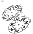
discharge chamber 12b is disposed at the radial center and thesuction chamber 12a is disposed at radial periphery to surround thedischarge chamber 12b, it is possible, as shown inFigures 4 and5 , to form on the end face of thevalve plate 11 opposing the cylinder block 2 through the circularthin plate 18grooves 11d extending from theholes 11c accommodating the through-bolts to the portions abutting thesuction valves 13 without interfering with thedischarge holes 11b and make thegrooves 11d extend beyond the portions opposing the roots of thesuction valves 13 to the portions near thesuction holes 11a, thereby applying the crank chamber pressure on the surfaces of thesuction valves 13 abutting thevalve plate 11 through theholes 2b formed in the cylinder block 2 and accommodating the through-bolts,holes 18b formed in the circularthin plate 18 and accommodating the through-bolts,holes 11c formed in thevalve plate 11 and accommodating the through bolts, and thegrooves 11d formed in the end face of thevalve plate 11 opposing the cylinder block 2. The pressure forces thesuction valves 13 in the opening direction. Thus, the forces for pushing thesuction valves 13 open become larger than that by the conventional technology, the delayed opening of thesuction valves 13 is prevented more effectively than by the conventional technology, and the self-excited vibration of the suction valves is prevented more effectively than by the conventional technology. - The present invention can be widely used in various kinds of reciprocating compressors including swash plate compressors, wobble plate compressors, etc.
-
-
Figure 1 is a sectional view of a variable displacement swash plate compressor in accordance with a preferred embodiment of the present invention. -
Figure 2 is a set of perspective views of the suction valves and the valve plate provided for the variable displacement swash plate compressor in accordance with a preferred embodiment of the present invention. -
Figure 3 is a set of perspective views of the suction valves and the valve plate ofFigure 2 wherein the suction valves are fitted on the valve plate. -
Figure 4 is a set of perspective views of the suction valves and the valve plate provided for the variable displacement swash plate compressor in accordance with another preferred embodiment of the present invention. -
Figure 5 is a set of perspective views of the suction valves and the valve plate ofFigure 4 wherein the suction valves are fitted on the valve plate. -
- 1
- Variable displacement swash plate compressor
- 2
- Cylinder block
- 2a
- Cylinder bore
- 2b
- Hole for accommodating through-bolt
- 3
- Crank chamber
- 4
- Front housing
- 5
- Rotation shaft
- 8
- Swash plate
- 10
- Piston
- 11 1
- Valve plate
- 11a
- Suction hole
- 11b
- Discharge hole
- 11c
- Hole for accommodating through-bolt
- 11d
- Groove
- 12a
- Suction chamber
- 12b
- Discharge chamber
- 13
- Suction valve
- 15
- Through-bolt
Claims (2)
- A reciprocating compressor comprising a cylinder block provided with cylinder bores, pistons fitted in the cylinder bores, a front housing opposing one of the end faces of the cylinder block to cooperate with the cylinder block and thereby form a crank chamber accommodating a piston driving mechanism, a valve plate opposing the other one of the end faces of the cylinder block and provided with suction holes and discharge holes communicating with the cylinder bores, a rear housing provided with a suction chamber and a discharge chamber and opposing the other one of the end faces of the cylinder block with the valve plate inserted between them, strap-shaped suction valves fitted on the end face of the valve plate opposing the cylinder block to abut the valve plate, thereby opening and closing the suction holes at tip portions, discharge valves fitted on the end face of the valve plate opposing the rear housing to open and close the discharge holes, and through-bolts passed through the front housing, the crank chamber, the cylinder block, the valve plate and the rear housing to assemble them as a unitary body, wherein the valve plate is provided with grooves extending from holes for accommodating the through-bolts to portions abutting the suction valves in the end face opposing the cylinder block.
- A reciprocating compressor of claim 1, wherein the grooves extend beyond the portions opposing the roots of the suction valves to the portions near the suction holes.
Applications Claiming Priority (2)
| Application Number | Priority Date | Filing Date | Title |
|---|---|---|---|
| JP2008087337A JP5065120B2 (en) | 2008-03-28 | 2008-03-28 | Reciprocating compressor |
| PCT/JP2009/054650 WO2009119316A1 (en) | 2008-03-28 | 2009-03-11 | Reciprocating compressor |
Publications (2)
| Publication Number | Publication Date |
|---|---|
| EP2280171A1 true EP2280171A1 (en) | 2011-02-02 |
| EP2280171A4 EP2280171A4 (en) | 2011-05-25 |
Family
ID=41113514
Family Applications (1)
| Application Number | Title | Priority Date | Filing Date |
|---|---|---|---|
| EP09724940A Withdrawn EP2280171A4 (en) | 2008-03-28 | 2009-03-11 | Reciprocating compressor |
Country Status (5)
| Country | Link |
|---|---|
| US (1) | US8684703B2 (en) |
| EP (1) | EP2280171A4 (en) |
| JP (1) | JP5065120B2 (en) |
| CN (1) | CN101970878B (en) |
| WO (1) | WO2009119316A1 (en) |
Cited By (1)
| Publication number | Priority date | Publication date | Assignee | Title |
|---|---|---|---|---|
| EP3023640A1 (en) * | 2014-11-10 | 2016-05-25 | LG Electronics Inc. | Reciprocating compressor |
Families Citing this family (7)
| Publication number | Priority date | Publication date | Assignee | Title |
|---|---|---|---|---|
| JP5324893B2 (en) * | 2008-11-18 | 2013-10-23 | サンデン株式会社 | Compressor valve plate device |
| JP5559720B2 (en) * | 2010-03-31 | 2014-07-23 | 株式会社豊田自動織機 | Compressor |
| AT509081B1 (en) * | 2010-04-08 | 2011-06-15 | Hoerbiger Kompressortech Hold | HOLLOW VALVE PLATE |
| BRPI1105143B1 (en) * | 2011-12-15 | 2021-07-27 | Embraco Indústria De Compressores E Soluções Em Refrigeração Ltda | SUCTION VALVE ASSEMBLY FOR ALTERNATIVE COMPRESSOR |
| CN104179656B (en) * | 2014-08-18 | 2016-09-21 | 合肥达因汽车空调有限公司 | A kind of variable displacement swash plate compressor |
| JP2016070167A (en) * | 2014-09-30 | 2016-05-09 | 株式会社ヴァレオジャパン | Reciprocation type compressor |
| CN104533596B (en) * | 2014-11-15 | 2017-01-18 | 汪培杰 | Design method of trigger wheel for fluid transfer device |
Family Cites Families (24)
| Publication number | Priority date | Publication date | Assignee | Title |
|---|---|---|---|---|
| US5044892A (en) * | 1990-03-05 | 1991-09-03 | General Motors Corporation | Swash plate compressor lubrication system |
| JP2587085Y2 (en) * | 1992-05-06 | 1998-12-14 | 株式会社豊田自動織機製作所 | Suction reed valve mechanism of piston type compressor |
| JPH0886279A (en) * | 1994-09-16 | 1996-04-02 | Toyota Autom Loom Works Ltd | Reciprocating type compressor |
| US5795139A (en) * | 1995-03-17 | 1998-08-18 | Kabushiki Kaisha Toyoda Jidoshokki Seisakusho | Swash plate type refrigerant compressor with improved internal lubricating system |
| JPH08254183A (en) * | 1995-03-17 | 1996-10-01 | Toyota Autom Loom Works Ltd | Swash plate type compressor |
| US5672053A (en) * | 1995-04-03 | 1997-09-30 | General Motors Corporation | Compressor reed valve with valve plate channel |
| JPH10196536A (en) * | 1997-01-13 | 1998-07-31 | Toyota Autom Loom Works Ltd | Deterioration preventing structure of sealing member in reciprocating compressor |
| JPH10299656A (en) * | 1997-04-22 | 1998-11-10 | Zexel Corp | Reciprocating compressor |
| JPH1162823A (en) * | 1997-08-08 | 1999-03-05 | Sanden Corp | Variable displacement compressor |
| JP2000329066A (en) * | 1999-05-19 | 2000-11-28 | Toyota Autom Loom Works Ltd | Suction valve construction of piston type compressor |
| JP4242990B2 (en) * | 1999-11-25 | 2009-03-25 | サンデン株式会社 | Swash plate compressor |
| JP2001193649A (en) * | 1999-12-28 | 2001-07-17 | Zexel Valeo Climate Control Corp | Reciprocating refrigerant compressor |
| US7004734B2 (en) * | 1999-12-28 | 2006-02-28 | Zexel Valco Climate Control Corporation | Reciprocating refrigerant compressor |
| FR2809459A1 (en) * | 2000-05-24 | 2001-11-30 | Sanden Corp | INCLINED CAM TYPE VARIABLE CYLINDER COMPRESSOR WITH CAPACITY CONTROL MECHANISM |
| JP2003028057A (en) * | 2001-07-13 | 2003-01-29 | Toyota Industries Corp | Throttle structure of variable displacement type compressor |
| US7390176B2 (en) * | 2001-10-05 | 2008-06-24 | Carrier Corporation | Multi-port suction reed valve with optimized tips |
| JP2005105975A (en) * | 2003-09-30 | 2005-04-21 | Calsonic Kansei Corp | Valve structure of compressor |
| KR20060096003A (en) * | 2003-09-30 | 2006-09-05 | 칼소닉 칸세이 가부시끼가이샤 | Compressor and suction valve structure |
| JP2007064196A (en) | 2005-08-05 | 2007-03-15 | Valeo Thermal Systems Japan Corp | Method for processing valve mechanism constituting member |
| JP4794274B2 (en) * | 2005-10-27 | 2011-10-19 | カルソニックカンセイ株式会社 | Variable capacity compressor |
| JP4737076B2 (en) * | 2006-05-19 | 2011-07-27 | 株式会社豊田自動織機 | Compressor |
| JP4706617B2 (en) * | 2006-11-03 | 2011-06-22 | 株式会社豊田自動織機 | Compressor suction throttle valve |
| JP4730317B2 (en) * | 2007-02-02 | 2011-07-20 | 株式会社豊田自動織機 | Double-head piston compressor |
| EP2088318A1 (en) * | 2008-02-05 | 2009-08-12 | Kabushiki Kaisha Toyota Jidoshokki | Swash plate compressor |
-
2008
- 2008-03-28 JP JP2008087337A patent/JP5065120B2/en not_active Expired - Fee Related
-
2009
- 2009-03-11 US US12/935,245 patent/US8684703B2/en not_active Expired - Fee Related
- 2009-03-11 EP EP09724940A patent/EP2280171A4/en not_active Withdrawn
- 2009-03-11 CN CN2009801098502A patent/CN101970878B/en not_active Expired - Fee Related
- 2009-03-11 WO PCT/JP2009/054650 patent/WO2009119316A1/en not_active Ceased
Cited By (2)
| Publication number | Priority date | Publication date | Assignee | Title |
|---|---|---|---|---|
| EP3023640A1 (en) * | 2014-11-10 | 2016-05-25 | LG Electronics Inc. | Reciprocating compressor |
| US10180131B2 (en) | 2014-11-10 | 2019-01-15 | Lg Electronics Inc. | Reciprocating compressor |
Also Published As
| Publication number | Publication date |
|---|---|
| JP2009243276A (en) | 2009-10-22 |
| US8684703B2 (en) | 2014-04-01 |
| JP5065120B2 (en) | 2012-10-31 |
| CN101970878B (en) | 2013-08-07 |
| US20110020158A1 (en) | 2011-01-27 |
| CN101970878A (en) | 2011-02-09 |
| EP2280171A4 (en) | 2011-05-25 |
| WO2009119316A1 (en) | 2009-10-01 |
Similar Documents
| Publication | Publication Date | Title |
|---|---|---|
| US8684703B2 (en) | Reciprocating compressor | |
| JP4514232B2 (en) | Compressor | |
| EP2865893B1 (en) | Valve assembly for variable swash plate compressor | |
| KR20140104300A (en) | Intake checking valve | |
| EP1174619A3 (en) | Swash plate compressor housing | |
| EP2045465A1 (en) | Compressor | |
| US9157427B2 (en) | Compressor | |
| KR20080106007A (en) | compressor | |
| US6632074B2 (en) | Pressure setting means for a multistage type piston compressor | |
| JP3858814B2 (en) | Adjustment method of rotating machine | |
| EP3604818A1 (en) | Oscillating piston-type compressor | |
| KR20150060199A (en) | Reciprocating compressor | |
| US8215924B2 (en) | Oil separating structure of variable displacement compressor | |
| EP1947336A1 (en) | Reciprocating compressor | |
| US6912948B2 (en) | Swash plate compressor | |
| KR20040086130A (en) | Piston type compressor | |
| KR101515643B1 (en) | Compressor | |
| KR20080055117A (en) | Variable displacement swash plate compressor | |
| KR101336436B1 (en) | Piston for swash plate type compressor | |
| EP2489877A1 (en) | Compressor | |
| KR100532133B1 (en) | Variable Swash Plate Type Compressor | |
| JP2002021717A (en) | Single head piston type compressor | |
| KR20040094155A (en) | A swash plate type compressor | |
| KR20110072317A (en) | Variable displacement swash plate compressor | |
| JP2007278180A (en) | Reciprocating compressor |
Legal Events
| Date | Code | Title | Description |
|---|---|---|---|
| PUAI | Public reference made under article 153(3) epc to a published international application that has entered the european phase |
Free format text: ORIGINAL CODE: 0009012 |
|
| 17P | Request for examination filed |
Effective date: 20101020 |
|
| AK | Designated contracting states |
Kind code of ref document: A1 Designated state(s): AT BE BG CH CY CZ DE DK EE ES FI FR GB GR HR HU IE IS IT LI LT LU LV MC MK MT NL NO PL PT RO SE SI SK TR |
|
| AX | Request for extension of the european patent |
Extension state: AL BA RS |
|
| A4 | Supplementary search report drawn up and despatched |
Effective date: 20110427 |
|
| STAA | Information on the status of an ep patent application or granted ep patent |
Free format text: STATUS: THE APPLICATION HAS BEEN WITHDRAWN |
|
| 18W | Application withdrawn |
Effective date: 20110526 |
|
| DAX | Request for extension of the european patent (deleted) |