EP2279970A1 - Method for conveying silicon granules in an encapsulated conveying channel - Google Patents
Method for conveying silicon granules in an encapsulated conveying channel Download PDFInfo
- Publication number
- EP2279970A1 EP2279970A1 EP10169347A EP10169347A EP2279970A1 EP 2279970 A1 EP2279970 A1 EP 2279970A1 EP 10169347 A EP10169347 A EP 10169347A EP 10169347 A EP10169347 A EP 10169347A EP 2279970 A1 EP2279970 A1 EP 2279970A1
- Authority
- EP
- European Patent Office
- Prior art keywords
- silicon
- conveyor
- encapsulated
- conveying device
- conveying
- Prior art date
- Legal status (The legal status is an assumption and is not a legal conclusion. Google has not performed a legal analysis and makes no representation as to the accuracy of the status listed.)
- Granted
Links
- 238000000034 method Methods 0.000 title claims abstract description 28
- 239000008187 granular material Substances 0.000 title claims abstract description 21
- 229910052710 silicon Inorganic materials 0.000 title claims description 21
- 239000010703 silicon Substances 0.000 title claims description 21
- XUIMIQQOPSSXEZ-UHFFFAOYSA-N Silicon Chemical compound [Si] XUIMIQQOPSSXEZ-UHFFFAOYSA-N 0.000 title claims description 19
- 230000005672 electromagnetic field Effects 0.000 claims abstract description 10
- 230000005284 excitation Effects 0.000 claims abstract description 4
- 230000006641 stabilisation Effects 0.000 claims abstract 2
- 238000011105 stabilization Methods 0.000 claims abstract 2
- 229910021420 polycrystalline silicon Inorganic materials 0.000 claims description 6
- 239000013078 crystal Substances 0.000 claims description 3
- 229910021421 monocrystalline silicon Inorganic materials 0.000 claims description 2
- 229910021422 solar-grade silicon Inorganic materials 0.000 claims description 2
- 238000002425 crystallisation Methods 0.000 claims 1
- 230000008025 crystallization Effects 0.000 claims 1
- 239000000463 material Substances 0.000 description 9
- 238000004519 manufacturing process Methods 0.000 description 7
- 229920003023 plastic Polymers 0.000 description 5
- 238000011109 contamination Methods 0.000 description 4
- 239000002245 particle Substances 0.000 description 4
- 239000002210 silicon-based material Substances 0.000 description 4
- 229910001220 stainless steel Inorganic materials 0.000 description 4
- 239000010935 stainless steel Substances 0.000 description 4
- 229920005591 polysilicon Polymers 0.000 description 3
- 239000000523 sample Substances 0.000 description 3
- 238000005299 abrasion Methods 0.000 description 2
- 239000000428 dust Substances 0.000 description 2
- 238000009434 installation Methods 0.000 description 2
- 238000005070 sampling Methods 0.000 description 2
- KPLQYGBQNPPQGA-UHFFFAOYSA-N cobalt samarium Chemical compound [Co].[Sm] KPLQYGBQNPPQGA-UHFFFAOYSA-N 0.000 description 1
- 230000008878 coupling Effects 0.000 description 1
- 238000010168 coupling process Methods 0.000 description 1
- 238000005859 coupling reaction Methods 0.000 description 1
- 238000009826 distribution Methods 0.000 description 1
- 238000005538 encapsulation Methods 0.000 description 1
- 229920002457 flexible plastic Polymers 0.000 description 1
- 229920001903 high density polyethylene Polymers 0.000 description 1
- 239000000696 magnetic material Substances 0.000 description 1
- 238000012423 maintenance Methods 0.000 description 1
- 229910052751 metal Inorganic materials 0.000 description 1
- 239000002184 metal Substances 0.000 description 1
- 239000000203 mixture Substances 0.000 description 1
- 229910000938 samarium–cobalt magnet Inorganic materials 0.000 description 1
- 239000007787 solid Substances 0.000 description 1
- 238000003860 storage Methods 0.000 description 1
- 238000003466 welding Methods 0.000 description 1
Images

Classifications
-
- B—PERFORMING OPERATIONS; TRANSPORTING
- B65—CONVEYING; PACKING; STORING; HANDLING THIN OR FILAMENTARY MATERIAL
- B65G—TRANSPORT OR STORAGE DEVICES, e.g. CONVEYORS FOR LOADING OR TIPPING, SHOP CONVEYOR SYSTEMS OR PNEUMATIC TUBE CONVEYORS
- B65G27/00—Jigging conveyors
- B65G27/10—Applications of devices for generating or transmitting jigging movements
- B65G27/16—Applications of devices for generating or transmitting jigging movements of vibrators, i.e. devices for producing movements of high frequency and small amplitude
- B65G27/24—Electromagnetic devices
-
- B—PERFORMING OPERATIONS; TRANSPORTING
- B29—WORKING OF PLASTICS; WORKING OF SUBSTANCES IN A PLASTIC STATE IN GENERAL
- B29B—PREPARATION OR PRETREATMENT OF THE MATERIAL TO BE SHAPED; MAKING GRANULES OR PREFORMS; RECOVERY OF PLASTICS OR OTHER CONSTITUENTS OF WASTE MATERIAL CONTAINING PLASTICS
- B29B9/00—Making granules
- B29B9/16—Auxiliary treatment of granules
- B29B2009/165—Crystallizing granules
Definitions
- the invention relates to a method for the promotion of silicon granules in an encapsulated conveyor trough.
- the object of the invention was therefore to provide a new system and a method for the promotion and silicon granules, in which the device without direct external connection in Pressure chamber can be housed and in which no large vibrational movements act on the granules to prevent abrasion of the granules and on the mechanical parts. Furthermore, the system should be easy to install outside the reactor to facilitate access.
- the invention relates to a method for conveying granular silicon by means of horizontal and / or vertical movement of the conveying device, characterized in that the conveying device is completely encapsulated to the outside and the forward movement of the granules by a tumbling motion of the conveyor by means of the excitation of at least one of the Conveyor mounted permanent magnet is generated by an electromagnetic field, wherein the electromagnetic field is applied from an outside of the pressure chamber arranged coil to the encapsulated device.
- the shaking movement of the method according to the invention takes place in the encapsulated conveyor trough by the tumbling movement of a permanent magnet, which is excited by an external alternating electromagnetic field.
- the conveying device can be completely encapsulated in a housing to the outside and requires no feedthroughs for electrical leads or compressed air lines.
- the conveyor device for the method according to the invention has at least two connection possibilities to the outside, preferably one on each side of the conveyor trough as an inlet and outlet. These connections are preferably designed as nozzles or flange connections to connect the conveyor pressure-tight to a pipeline, a reactor or a container for storing granules.
- the device can be used for example as a certified pressure device in a fluidized bed plant for the production of polysilicon.
- the conveyor can be operated depending on the design of the components in a vacuum or at elevated pressure.
- the process is preferably carried out at a pressure of 0.1 bar to 100 bar, more preferably at 1 to 10 bar.
- the conveyor can also be used in systems with high design pressures and / or high purity requirements.
- the conveyor trough inside the conveyor itself is not pressurized component and can therefore be performed in a suitable material for the respective material.
- materials for housing, internal gutter, compensators and magnets can be selected, which are specially designed for longevity and which do not or little contaminate the product to be conveyed. As a result, the maintenance is very low.
- the housing of the encapsulated conveyor trough preferably consists of a metallic pipe with welding socket and flange connection to the inlets and outlets.
- the conveyor trough within the encapsulated device is movably mounted on the housing.
- the conveyor trough is a pipe in the form of a closed tube with openings at inlet and outlet, which is flexibly connected at least one point with the outer dwelling.
- the flexible mounts can represent, for example, springs, rubber bands, movable straps or other flexible devices.
- inlet and outlet nozzles are provided with plastic liners.
- a strong permanent magnet is attached at one end of the plastic tube. This can be connected, for example, in a separate chamber attached to this tube to avoid contamination of the interior by the magnet.
- a strong cylindrical permanent magnet is welded into a plastic container which is attached to the conveyor tube.
- the freedom of movement within the chamber for the magnet is to be dimensioned so that the permanent magnet on the one hand has room for its wobbling movement, which sets the conveyor trough in vibration, but on the other hand does not allow free rotation of the magnet.
- the tumbling motion of the permanent magnet is excited by an external electromagnetic alternating field of a coil that is coupled to the permanent magnet.
- the axis of the magnet must be arranged perpendicular to the coil axis (axis of the electromagnetic field). In order to protect the permanent magnet from abrasion by the permanent wobbling, this is preferably coated or welded in a jacket made of stainless steel.
- the permanent magnets all technically usable magnets can be used. Preference is given to magnets containing rare earths, particularly preferably samarium-cobalt magnets. The exact composition of the magnets and their magnetic force are not critical to the invention. In principle, the permanent magnet may have any shapes, but preferably a cylindrical shape is used.
- magnets with a size ratio (height to diameter) of 1.3: 1 are used.
- the Magnetbehausung in which the permanent magnet is housed requires sufficient space so that it can move freely in a tumbling motion and thus produces a correct momentum transfer to the delivery pipe.
- the ratio of the cavity of the magnetic housing to the magnet diameter is preferably 1.2: 1 and the preferred height of the magnetic chamber to the magnetic height 1.2: 1.
- the permanent magnet used is preferably installed standing. When creating an alternating field, the permanent magnet tries to center in the field and transmits in this rotary motion pulses to the wall of the Magnetbehausung and thus to the attached conveyor trough.
- the flow rate of silicon granules through the conveyor is expressed as an analogous quantity via the modulation of amplitude (coil current) and frequency of the alternating electromagnetic field of the coil, e.g. set by means of a frequency converter.
- the frequency is adjusted to the natural frequency of the conveyor trough in the respective installation situation.
- a single-phase magnetic field is used.
- Preferred is a variable frequency of 0.1 to 1000 Hz, more preferably 5 to 100 Hz.
- the frequency is tuned to resonance according to the installation conditions.
- a frequency converter can be used for tuning.
- the frequency of the tumbling motion corresponds to the frequency of the exciter field.
- a plurality of inputs and outputs may be attached to the conveying device, for example for a plurality of feed containers or for taking smaller quantities of granulate for sampling from the conveying path thereof.
- an encapsulated conveying device in which an additional device for taking a product sample is possible ( FIG. 2 ).
- two outlet nozzles (9 and 10) are arranged one behind the other.
- the shaking movement of the channel conveys the material further to the second outlet (10), from which it then flows into the sample strand.
- the sampling is stopped by reopening the valve below the first outlet.
- the inventive method can also be used to promote almost all other solid particles.
- the inventive method was in a conveyor trough according to FIG. 1 executed.
- the housing (1) made of stainless steel had a diameter of 120mm and a length of 1000mm.
- the delivery pipe (2) consisted of a plastic pipe with a diameter of 50mm and a length of 700mm.
- the plastic housing for the permanent magnet had a diameter of 50mm and a length of 100mm.
- Flexible plastic expansion joints (3) were installed between the inlet and outlet flange and the delivery pipe.
- the retaining springs (7) consisted of metal and plastic.
- As flange stainless steel Anschweisflansche were selected to seal the device by means of DIN flange gaskets.
- a coil (6) was wound on a cylinder and positioned on the outer tube at the level of the permanent magnet (4).
- a cobalt-samarium magnet with an outside diameter of 30 mm and a length of 40 mm was used in a stainless steel jacket.
- the frequency of the wobble was varied between 0.1 and 70 Hz. It was possible to continuously adjust the transport of the conveyed material from 0 to 100 kg / h.
- the conveyed goods were high-purity silicon granules (hyper-pure silicon for electronic and solar applications) and a particle size distribution of 20 ⁇ m to 1000 ⁇ m and average particle sizes of between 300 ⁇ m and 500 ⁇ m.
Abstract
Description
Die Erfindung betrifft ein Verfahren zur Förderung von Siliciumgranulat in einer gekapselten Förderrinne.The invention relates to a method for the promotion of silicon granules in an encapsulated conveyor trough.
Bei der Herstellung von polykristallinem Siliciumgranulat in einem Wirbelschichtreaktor ist es im laufenden Prozess nötig, Siliciummaterial in regelmäßigen Abständen oder kontinuierlich in den Reaktor zu dosieren und an anderer Stelle fertig gewachsenes Granulat aus dem Reaktor zu entnehmen.In the production of polycrystalline silicon granules in a fluidized bed reactor, it is necessary in the current process to meter silicon material into the reactor at regular intervals or continuously and to remove ready-grown granules from the reactor elsewhere.
Dazu werden in der Produktion meistens einfache Auf-Zu-Armaturen, wie beispielsweise Schieber, eingesetzt. Um eine Kontamination des hochreinen Siliciums auszuschließen werden dabei in der Regel Schieber aus Siliciummaterial verwendet. Nachteilig dabei ist aber der hohe Verschleiß dieser Schieber, der sich aus der Abrassivität von Siliciumgranulat ergibt. Aus diesem Grund müssen diese Armaturen daher in einem kurzen Zyklus getauscht werden.For this purpose, mostly simple on-off valves, such as slides, are used in production. In order to exclude contamination of the high-purity silicon, slides made of silicon material are generally used. The disadvantage here is the high wear of these slides, which results from the Abrassivität of silicon granules. For this reason, these fittings must therefore be replaced in a short cycle.
Ein weiterer Nachteil dieser Schieber ist die Neigung zum Verblocken. In diesem Fall muss die jeweilige Anlage dabei abgestellt werden um die Verblockung in der Armatur manuell zu beseitigen. Zudem kann durch die einfache Auf-Zu-Steuerung nur eine begrenzte Regelung der Dosier- und Abzugsmenge erreicht werden.Another disadvantage of these slides is the tendency to lock. In this case, the respective system must be turned off to manually eliminate the blockage in the valve. In addition, only a limited control of the metering and withdrawal amount can be achieved by the simple on-off control.
Üblicherweise werden in der Technik zur Förderung von Schüttgütern offene sowie geschlossene Förderrinnen mit einer direkten Einkopplung durch elektrische oder pneumatische Vibrationsmotoren verwendet.Usually open and closed conveyor troughs with a direct coupling by electric or pneumatic vibration motors are used in the art for conveying bulk materials.
Bei der Herstellung von Siliciumeinkristallen muss die Beladung und das Nachchargieren eines Schmelztiegels mit hochreinem Siliciummaterial aus Reinheitsgründen unter Vakuumatmosphäre durchgeführt werden.In the production of silicon single crystals, the charging and recharging of a crucible with high purity silicon material must be carried out for reasons of purity under a vacuum atmosphere.
Aus
Aus
Bei der Herstellung von Polysiliciumgranulat in einem Wirbelschichtreaktor stellt der Reaktor mit seinen Zugabe- und Abzugsleitungen dagegen ein geschlossenes System dar, dass in der Regel mit einem Auslegungsdruck von bis zu 10 bar Überdruck arbeitet. Aus diesem Grund können bekannte Schwingförderrinnen mit elektrischem oder pneumatischem Vibrationsmotor, die direkt an der Schwingrinne einkoppeln, nicht eingesetzt werden.In the production of polysilicon granulate in a fluidized bed reactor, however, the reactor with its addition and withdrawal lines is a closed system that usually works with a design pressure of up to 10 bar overpressure. For this reason, known Schwingförderrinnen with electric or pneumatic vibration motor, which couple directly to the vibrating trough, can not be used.
Aufgabe der Erfindung war es daher ein neues System und ein Verfahren zur Förderung und Siliciumgranulat bereit zu stellen, bei dem die Vorrichtung ohne direkte äußere Verbindung im Druckraum eingehaust werden kann und bei dem keine großen Vibrationsbewegungen auf das Granulat einwirken um einen Abrieb am Granulat und an den mechanischen Teilen zu verhindern. Weiterhin soll das System wartungsfreundlich außerhalb des Reaktors angebracht werden können, um einen eventuellen Zugriff zu erleichtern.The object of the invention was therefore to provide a new system and a method for the promotion and silicon granules, in which the device without direct external connection in Pressure chamber can be housed and in which no large vibrational movements act on the granules to prevent abrasion of the granules and on the mechanical parts. Furthermore, the system should be easy to install outside the reactor to facilitate access.
Gegenstand der Erfindung ist ein Verfahren zur Förderung von granulatförmigen Silicium mittels horizontaler und /oder vertikaler Bewegung der Fördervorrichtung, dadurch gekennzeichnet, dass die Fördervorrichtung nach außen vollständig abgekapselt ist und die Vorwärtsbewegung des Granulats durch eine Taumelbewegung der Fördervorrichtung mittels der Anregung von mindestens einem an der Fördervorrichtung angebrachten Permanentmagneten durch ein elektromagnetisches Feldes erzeugt wird, wobei das elektromagnetische Feld von einer außerhalb des Druckraumes angeordneten Spule an die gekapselte Vorrichtung angelegt wird.The invention relates to a method for conveying granular silicon by means of horizontal and / or vertical movement of the conveying device, characterized in that the conveying device is completely encapsulated to the outside and the forward movement of the granules by a tumbling motion of the conveyor by means of the excitation of at least one of the Conveyor mounted permanent magnet is generated by an electromagnetic field, wherein the electromagnetic field is applied from an outside of the pressure chamber arranged coil to the encapsulated device.
Gegenüber Förderrinnen, die mittels Vibrationsmotoren angeregt werden, erfolgt die Rüttelbewegung des erfindungsgemäßen Verfahrens in der gekapselten Förderrinne durch die Taumelbewegung eines Permanentmagneten, der durch ein externes elektromagnetisches Wechselfeld angeregt wird. Dadurch läßt sich die Fördervorrichtung vollständig in einem Gehäuse nach außen kapseln und benötigt keine Durchführungen für elektrische Zuleitungen oder Druckluftleitungen.Compared with conveyor troughs, which are excited by means of vibration motors, the shaking movement of the method according to the invention takes place in the encapsulated conveyor trough by the tumbling movement of a permanent magnet, which is excited by an external alternating electromagnetic field. As a result, the conveying device can be completely encapsulated in a housing to the outside and requires no feedthroughs for electrical leads or compressed air lines.
Die Fördervorrichtung für das erfindungsgemäße Verfahren besitzt nach außen mindestens zwei Anschlussmöglichkeiten, vorzugsweise jeweils eine an jeder Seite der Förderrinne als Ein- und Auslass. Diese Anschlüsse sind bevorzugt als Stutzen oder Flanschverbindungen ausgebildet um die Fördervorrichtung druckdicht an eine Rohrleitung, einen Reaktor oder einen Behälter zur Bevorratung von Granulat anzuschließen. Dadurch kann die Vorrichtung beispielsweise als zertifiziertes Druckgerät in einer Wirbelschichtanlage zur Herstellung von Polysilicium eingesetzt werden.The conveyor device for the method according to the invention has at least two connection possibilities to the outside, preferably one on each side of the conveyor trough as an inlet and outlet. These connections are preferably designed as nozzles or flange connections to connect the conveyor pressure-tight to a pipeline, a reactor or a container for storing granules. As a result, the device can be used for example as a certified pressure device in a fluidized bed plant for the production of polysilicon.
Die Fördervorrichtung kann je nach Auslegung der Bauteile im Vakuum oder mit erhöhtem Druck betrieben werden. Bevorzugt wird das Verfahren bei einem Druck von 0,1 bar bis 100 bar, besonders bevorzugt bei 1 bis 10 bar ausgeführt.The conveyor can be operated depending on the design of the components in a vacuum or at elevated pressure. The process is preferably carried out at a pressure of 0.1 bar to 100 bar, more preferably at 1 to 10 bar.
Durch die vollständige Kapselung in einem Gehäuse kann die Fördervorrichtung auch in Anlagen mit hohen Auslegungsdrücken und/ oder hohen Reinheitsansprüchen eingesetzt werden.Due to the complete encapsulation in a housing, the conveyor can also be used in systems with high design pressures and / or high purity requirements.
Die Förderrinne im Inneren der Fördervorrichtung ist selbst kein druckbeaufschlagtes Bauteil und kann daher in einem für das jeweilige Fördergut geeigneten Werkstoff ausgeführt werden. Dadurch können Werkstoffe für Gehäuse, innenliegende Rinne, Kompensatoren und Magneten gewählt werden, die speziell auf Langlebigkeit ausgelegt sind und die das zu fördernde Produkt nicht oder wenig kontaminieren. Dadurch ist der Wartungsaufwand sehr gering.The conveyor trough inside the conveyor itself is not pressurized component and can therefore be performed in a suitable material for the respective material. As a result, materials for housing, internal gutter, compensators and magnets can be selected, which are specially designed for longevity and which do not or little contaminate the product to be conveyed. As a result, the maintenance is very low.
Das Gehäuse der gekapselten Förderrinne besteht bevorzugt aus einer metallischen Rohrleitung mit Anschweißstutzen und Flanschverbindung an den Ein- und Ausläufen.The housing of the encapsulated conveyor trough preferably consists of a metallic pipe with welding socket and flange connection to the inlets and outlets.
Die Förderrinne innerhalb der gekapselten Vorrichtung ist am Gehäuse beweglich befestigt. Bevorzugt handelt es sich bei der Förderrinne um eine Rohrleitung in Form eines geschlossenen Rohres mit Öffnungen an Ein- und Auslauf, welches an mindestens einem Punkt mit der äußeren Behausung flexibel verbunden ist. Die flexiblen Halterungen können beispielsweise Federn, Gummibänder, bewegliche Haltebänder oder sonstige flexible Einrichtungen darstellen.The conveyor trough within the encapsulated device is movably mounted on the housing. Preferably, the conveyor trough is a pipe in the form of a closed tube with openings at inlet and outlet, which is flexibly connected at least one point with the outer dwelling. The flexible mounts can represent, for example, springs, rubber bands, movable straps or other flexible devices.
Aus Gründen der Produktreinheit sind Ein- und Auslaufstutzen mit Kunststoffinlinern versehen. An einem Ende des Kunststoffrohres ist ein starker Permanentmagnet befestigt. Dieser kann beispielsweise in einer an diesem Rohr befestigten separaten Kammer angeschlossen sein, um eine Kontamination des Innenraums durch den Magneten zu vermeiden. Besonders bevorzugt ist eine Ausführung bei der ein starker zylinderförmiger Permanentmagnet in ein Kunstoffbehältnis eingeschweißt ist, welches am Förderrohr angebracht ist.For reasons of product purity, inlet and outlet nozzles are provided with plastic liners. At one end of the plastic tube, a strong permanent magnet is attached. This can be connected, for example, in a separate chamber attached to this tube to avoid contamination of the interior by the magnet. Especially preferred is an embodiment in which a strong cylindrical permanent magnet is welded into a plastic container which is attached to the conveyor tube.
Die Bewegungsfreiheit innerhalb der Kammer für den Magneten ist so zu bemessen, daß der Permanentmagnet einerseits Spielraum für seine Taumelbewegung hat, welche die Förderrinne in Schwingung versetzt, andererseits aber keine freie Drehbewegung des Magneten zuläßt.The freedom of movement within the chamber for the magnet is to be dimensioned so that the permanent magnet on the one hand has room for its wobbling movement, which sets the conveyor trough in vibration, but on the other hand does not allow free rotation of the magnet.
Die Taumelbewegung des Permanentmagneten wird durch ein externes elektromagnetisches Wechselfeld einer Spule angeregt, dass mit dem Permanentmagneten gekoppelt ist.The tumbling motion of the permanent magnet is excited by an external electromagnetic alternating field of a coil that is coupled to the permanent magnet.
Die Achse des Magneten muß senkrecht zur Spulenachse (Achse des elektromagnetischen Feldes) angeordnet sein. Um den Permanentmagneten vor Abrieb durch die permanenten Taumelbewegungen zu schützen, wird dieser vorzugsweise beschichtet oder in einen Mantel aus Edelstahl eingeschweißt.The axis of the magnet must be arranged perpendicular to the coil axis (axis of the electromagnetic field). In order to protect the permanent magnet from abrasion by the permanent wobbling, this is preferably coated or welded in a jacket made of stainless steel.
Als Materialen für den Permanentmagneten können alle technisch verwendbaren Magneten eingesetzt werden. Bevorzugt werden Magneten enthaltend seltene Erden, besonders bevorzugt Samarium-Kobalt Magneten. Die genaue Zusammensetzung der Magneten und deren Magnetkraft sind nicht entscheidend für die Erfindung. Grundsätzlich kann der Permanentmagnet beliebige Formen besitzen, vorzugsweise wird aber eine zylindrische Form eingesetzt.As materials for the permanent magnets all technically usable magnets can be used. Preference is given to magnets containing rare earths, particularly preferably samarium-cobalt magnets. The exact composition of the magnets and their magnetic force are not critical to the invention. In principle, the permanent magnet may have any shapes, but preferably a cylindrical shape is used.
Bevorzugt kommen Magneten mit einem Größenverhältnis (Höhe zu Durchmesser) von 1,3:1 zum Einsatz.
Die Magnetbehausung, in dem der Permanentmagnet untergebracht ist benötigt ausreichend Freiraum damit sich dieser in einer Taumelbewegung frei bewegen kann und damit eine korrekte Impulsübertragung auf das Förderrohr entsteht. Das Verhältnis des Hohlraumes der Magnetbehausung zum Magnetdurchmesser beträgt bevorzugt 1,2:1 und die bevorzugte Höhe der Magnetkammer zur Magnethöhe 1,2:1.Preferably, magnets with a size ratio (height to diameter) of 1.3: 1 are used.
The Magnetbehausung, in which the permanent magnet is housed requires sufficient space so that it can move freely in a tumbling motion and thus produces a correct momentum transfer to the delivery pipe. The ratio of the cavity of the magnetic housing to the magnet diameter is preferably 1.2: 1 and the preferred height of the magnetic chamber to the magnetic height 1.2: 1.
Der verwendete Permanentmagnet wird bevorzugt stehend eingebaut. Beim Anlegen eines Wechselfeldes versucht sich der Permanentmagnet im Feld zu zentrieren und überträgt bei dieser Drehbewegung Impulse an die Wand der Magnetbehausung und damit an die daran befestigte Förderrinne.The permanent magnet used is preferably installed standing. When creating an alternating field, the permanent magnet tries to center in the field and transmits in this rotary motion pulses to the wall of the Magnetbehausung and thus to the attached conveyor trough.
Die Durchsatzmenge von Siliciumgranulat durch die Fördervorrichtung wird als analoge Größe über die Modulation von Amplitude (Spulenstrom) und Frequenz des elektromagnetischen Wechselfeldes der Spule z.B. mittels eines Frequenzumrichters eingestellt. Die Frequenz wird dabei auf die Eigenfrequenz der Förderrinne in der jeweiligen Einbausituation abgestimmt. Durch die Auswahl des entsprechenden Magnetmaterials, die Dimensionierung des Hohlraumdurchmessers, die Neigung der inneren Förderrinne und die Größe des Permanentmagneten können Arbeitsbereiche für unterschiedliche Anwendungensfälle definiert werden.The flow rate of silicon granules through the conveyor is expressed as an analogous quantity via the modulation of amplitude (coil current) and frequency of the alternating electromagnetic field of the coil, e.g. set by means of a frequency converter. The frequency is adjusted to the natural frequency of the conveyor trough in the respective installation situation. By selecting the appropriate magnetic material, the dimensioning of the cavity diameter, the inclination of the inner conveyor trough and the size of the permanent magnet working areas can be defined for different applications.
Zur Anregung des Magneten wird ein einphasiges Magnetfeld verwendet. Bevorzugt wird dabei eine variablen Frequenz von 0,1 bis 1000 Hz, besonders bevorzugt 5 bis 100 Hz. Die Frequenz wird entsprechend den Einbaugegebenheiten auf Resonanz abgestimmt. Zur Abstimmung kann beispielsweise ein Frequenzumrichter eingesetzt werden. Die Frequenz der Taumelbewegung entspricht der Frequenz des Erregerfeldes.To excite the magnet, a single-phase magnetic field is used. Preferred is a variable frequency of 0.1 to 1000 Hz, more preferably 5 to 100 Hz. The frequency is tuned to resonance according to the installation conditions. For example, a frequency converter can be used for tuning. The frequency of the tumbling motion corresponds to the frequency of the exciter field.
Zur Einstellung der benötigten Durchsatzmenge der Förderrinne kann die Stromamplitude stufenlos geregelt werden. Dies erfolgt bevorzugt in einem Bereich von 0,1 bis 100A, besonders bevorzugt in einem Bereich von 0,1 bis 5 A.
Die Feldstärke ergibt sich aus der eingesetzten Ampere-Windungszahl und variiert mit der für die benötigte Fördermenge eingestellten Stromstärke.
-
Figur 1
The field strength results from the ampere-turn number used and varies with the set current for the required flow rate.
-
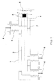
FIG. 1 shows an embodiment of the method according to the invention. The conveyor trough (2) is pressure-tight within a housing (1). For flexible connection of the inside lying conveyor trough (2) this is connected to the input and output flange by means of a flexible compensator (3). The conveyor trough itself is also flexibly connected within the dwelling (1) via a plurality of retaining springs (7). At one end of the internal conveyor trough (2), a housing (5) for a permanent magnet (4) is mounted. This is brought into motion by an externally applied alternating field (6). As a result of the movement of the inner conveyor channel (2), the silicon granules introduced through the feed opening (8) are moved forward as far as the opening for the product outlet (9).
Es können auch mehrere Ein- und Ausgänge an der Fördervorrichtung angebracht sein, beispielsweise für mehrere Vorlagebehälter oder zur Entnahme kleinerer Granulatmengen zur Beprobung aus deren Förderweg.It is also possible for a plurality of inputs and outputs to be attached to the conveying device, for example for a plurality of feed containers or for taking smaller quantities of granulate for sampling from the conveying path thereof.
Als eine besondere Ausführungsform des erfindungsgemäßen Verfahrens wird eine gekapselte Fördervorrichtung eingesetzt, bei der eine zusätzliche Vorrichtung für die Entnahme einer Produktprobe möglich ist (
Das erfindungsgemäße Verfahren kann auch zur Förderung nahezu aller anderen Feststoffpartikel eingesetzt werden. Besonders bevorzugt wir das erfindungsgemäße Verfahren zur Förderung von hochreinem Silicium, wie beispielsweise solar-grade-silicon für die Herstellung von Solarzellen oder hyper-pure-silicon für die Herstellung von mono- oder multikristallinen Siliciumkristallen für die Elektroindustrie.The inventive method can also be used to promote almost all other solid particles. We particularly prefer the inventive method for the promotion of high-purity silicon, such as solar grade silicon for the production of solar cells or hyper-pure-silicon for the production of monocrystalline or multicrystalline silicon crystals for the electrical industry.
Anhand des folgenden Beispiels soll die Erfindung näher erläutert werden.The invention will be explained in more detail with reference to the following example.
Das erfindungsgemäße Verfahren wurde in einer Förderrinne gemäß
Bei dem Fördergut handelte es sich um Siliciumgranulat mit hohem Reinheitsgrad (hyper-pure silicon for electronic and solar applications) und einer Korngrößenverteilung von 20µm bis 1000µm und mittleren Korngrößen zwischen 300µm und 500µm.The conveyed goods were high-purity silicon granules (hyper-pure silicon for electronic and solar applications) and a particle size distribution of 20 μm to 1000 μm and average particle sizes of between 300 μm and 500 μm.
Am Siliciumgranulat und an der Vorrichtung selbst konnten nach dem Durchlaufen der erfindungsgemäßen Vorrichtung keine Verunreinigung festgestellt werden.On the silicon granules and on the device itself no contamination could be detected after passing through the device according to the invention.
Claims (11)
Applications Claiming Priority (1)
| Application Number | Priority Date | Filing Date | Title |
|---|---|---|---|
| DE102009028166A DE102009028166A1 (en) | 2009-07-31 | 2009-07-31 | Method of conveying silicon granules in an encapsulated conveyor trough |
Publications (2)
| Publication Number | Publication Date |
|---|---|
| EP2279970A1 true EP2279970A1 (en) | 2011-02-02 |
| EP2279970B1 EP2279970B1 (en) | 2011-06-22 |
Family
ID=42938215
Family Applications (1)
| Application Number | Title | Priority Date | Filing Date |
|---|---|---|---|
| EP10169347A Active EP2279970B1 (en) | 2009-07-31 | 2010-07-13 | Method for conveying silicon granules in an encapsulated conveying channel |
Country Status (9)
| Country | Link |
|---|---|
| US (1) | US8939277B2 (en) |
| EP (1) | EP2279970B1 (en) |
| JP (1) | JP5394336B2 (en) |
| KR (1) | KR101242019B1 (en) |
| CN (1) | CN101987694B (en) |
| AT (1) | ATE513773T1 (en) |
| CA (1) | CA2708997C (en) |
| DE (1) | DE102009028166A1 (en) |
| ES (1) | ES2366017T3 (en) |
Families Citing this family (8)
| Publication number | Priority date | Publication date | Assignee | Title |
|---|---|---|---|---|
| JP5255734B1 (en) * | 2011-09-05 | 2013-08-07 | ダイヤモンドエンジニアリング株式会社 | Powder supply apparatus and powder supply method |
| DE102013215096A1 (en) * | 2013-08-01 | 2015-02-05 | Wacker Chemie Ag | Oscillating conveyor and method for conveying silicon fragments |
| DE102014200080A1 (en) | 2014-01-08 | 2015-07-09 | Wacker Chemie Ag | Process for producing granular polysilicon |
| DE102015203654A1 (en) * | 2015-03-02 | 2016-09-08 | Wacker Chemie Ag | Promotion and fractionation of polysilicon granules in a conveyor trough |
| DE102015209589A1 (en) * | 2015-05-26 | 2016-12-01 | Wacker Chemie Ag | Apparatus for conveying a product stream of polysilicon or polysilicon granules |
| CN105084009A (en) * | 2015-09-09 | 2015-11-25 | 上海隆麦机械设备工程有限公司 | Special expansion joint for pneumatic material conveying system |
| WO2017172748A1 (en) * | 2016-03-30 | 2017-10-05 | Sitec Gmbh | Systems and methods for dust suppressed silicon charging in a vacuum |
| US10040637B2 (en) | 2016-10-25 | 2018-08-07 | Rec Silicon Inc | Oscillatory feeder |
Citations (4)
| Publication number | Priority date | Publication date | Assignee | Title |
|---|---|---|---|---|
| GB1162989A (en) * | 1965-10-26 | 1969-09-04 | Rex Chainbelt Inc | Vibration Generator Controls |
| US5462010A (en) | 1991-10-15 | 1995-10-31 | Shin-Etsu Handotai Co., Ltd. | Apparatus for supplying granular raw material for a semiconductor single crystal pulling apparatus |
| EP1043249A1 (en) * | 1999-04-01 | 2000-10-11 | Wacker-Chemie GmbH | Vibratory conveyor and method for feeding bulk silicium |
| US6609870B2 (en) | 2001-10-23 | 2003-08-26 | Memc Electronic Materials, Inc. | Granular semiconductor material transport system and process |
Family Cites Families (17)
| Publication number | Priority date | Publication date | Assignee | Title |
|---|---|---|---|---|
| US2762658A (en) * | 1951-12-29 | 1956-09-11 | Houdry Process Corp | Method and apparatus for elevating granular material |
| JPS6270667U (en) | 1985-10-23 | 1987-05-06 | ||
| CN2035347U (en) | 1988-11-07 | 1989-04-05 | 天津大学 | Low-frequency stable-amplitude electromagnetic vibration conveyer |
| JPH0342631A (en) * | 1989-07-11 | 1991-02-22 | Citizen Watch Co Ltd | Production of mim type nonlinear switching element |
| JPH0818007B2 (en) | 1989-10-31 | 1996-02-28 | 有限会社パウドコーポレイション | Vibration device for mesh / membrane |
| CN2083571U (en) | 1990-11-27 | 1991-08-28 | 绍兴县五金标准件二厂 | Electromagnetic vibration feeding machine |
| US5718581A (en) * | 1995-05-09 | 1998-02-17 | Danville Manufacturing, Inc. | Air abrasive particle apparatus |
| JPH09142631A (en) | 1995-11-21 | 1997-06-03 | Sumitomo Special Metals Co Ltd | Rectilinear vibration feeder |
| US5997234A (en) * | 1997-04-29 | 1999-12-07 | Ebara Solar, Inc. | Silicon feed system |
| CN2321476Y (en) * | 1998-01-13 | 1999-06-02 | 徐龙生 | Pain stopping therapeutic apparatus |
| US6711958B2 (en) * | 2000-05-12 | 2004-03-30 | Endress + Hauser Flowtec Ag | Coriolis mass flow rate/density/viscoy sensor with two bent measuring tubes |
| DE10312706B4 (en) | 2003-03-21 | 2005-09-22 | Feintool International Holding | A linear vibratory conveyor |
| US7371269B2 (en) * | 2004-12-28 | 2008-05-13 | Techno Takatsuki Co., Ltd. | Electromagnetic vibrating pump |
| WO2006115145A1 (en) * | 2005-04-21 | 2006-11-02 | Kyoto University | Powdery/granular material fluidity evaluating device and method |
| JP2006298629A (en) * | 2005-04-25 | 2006-11-02 | Matsushita Electric Ind Co Ltd | Material supply device and material supply method |
| JP2008189406A (en) * | 2007-02-01 | 2008-08-21 | Shinko Electric Co Ltd | Vibration feeding device |
| US7553418B2 (en) * | 2007-08-18 | 2009-06-30 | Khudenko Engineering, Inc. | Method for water filtration |
-
2009
- 2009-07-31 DE DE102009028166A patent/DE102009028166A1/en not_active Withdrawn
-
2010
- 2010-07-05 CA CA2708997A patent/CA2708997C/en not_active Expired - Fee Related
- 2010-07-13 EP EP10169347A patent/EP2279970B1/en active Active
- 2010-07-13 AT AT10169347T patent/ATE513773T1/en active
- 2010-07-13 ES ES10169347T patent/ES2366017T3/en active Active
- 2010-07-14 KR KR1020100067911A patent/KR101242019B1/en active IP Right Grant
- 2010-07-27 US US12/844,218 patent/US8939277B2/en active Active
- 2010-07-30 CN CN201010243425.7A patent/CN101987694B/en active Active
- 2010-08-02 JP JP2010173519A patent/JP5394336B2/en active Active
Patent Citations (4)
| Publication number | Priority date | Publication date | Assignee | Title |
|---|---|---|---|---|
| GB1162989A (en) * | 1965-10-26 | 1969-09-04 | Rex Chainbelt Inc | Vibration Generator Controls |
| US5462010A (en) | 1991-10-15 | 1995-10-31 | Shin-Etsu Handotai Co., Ltd. | Apparatus for supplying granular raw material for a semiconductor single crystal pulling apparatus |
| EP1043249A1 (en) * | 1999-04-01 | 2000-10-11 | Wacker-Chemie GmbH | Vibratory conveyor and method for feeding bulk silicium |
| US6609870B2 (en) | 2001-10-23 | 2003-08-26 | Memc Electronic Materials, Inc. | Granular semiconductor material transport system and process |
Also Published As
| Publication number | Publication date |
|---|---|
| CN101987694B (en) | 2015-08-19 |
| DE102009028166A1 (en) | 2011-02-03 |
| JP2011032100A (en) | 2011-02-17 |
| KR20110013229A (en) | 2011-02-09 |
| US8939277B2 (en) | 2015-01-27 |
| CN101987694A (en) | 2011-03-23 |
| EP2279970B1 (en) | 2011-06-22 |
| JP5394336B2 (en) | 2014-01-22 |
| CA2708997C (en) | 2012-11-27 |
| CA2708997A1 (en) | 2011-01-31 |
| ES2366017T3 (en) | 2011-10-14 |
| US20110024266A1 (en) | 2011-02-03 |
| ATE513773T1 (en) | 2011-07-15 |
| KR101242019B1 (en) | 2013-03-11 |
Similar Documents
| Publication | Publication Date | Title |
|---|---|---|
| EP2279970B1 (en) | Method for conveying silicon granules in an encapsulated conveying channel | |
| EP0937004B1 (en) | Process and device for pneumatically conveying powdery substances | |
| EP1106547B1 (en) | Device and method for pneumatically conveying powdered materials, and use of the device | |
| EP1688718B1 (en) | Method and device for dosing and pneumatic conveyance of low flowability bulk material | |
| EP1776301B1 (en) | Device and method for pneumatically conveying bulk materials in a dense flow method | |
| CN102616501B (en) | Powder feeding device | |
| EP1619124A1 (en) | Device and procedure for filling powder-like products | |
| CN1375426A (en) | Power filling method and apparatus | |
| EP1742725B1 (en) | Method and device for pneumatic treatment of powder materials | |
| WO2016116427A1 (en) | Apparatus and method for filling an open container | |
| CN205294015U (en) | A screw feeder for preparing rare earth oxide | |
| EP1427657B1 (en) | Device and method for transferring a dusty, powdery, grain-like or granular conveyed material out of a storage receptacle and into a working or transfer receptacle or a similar accommodating space | |
| DE2805945C3 (en) | Device for the continuous feeding and emptying of a device operating in a vacuum | |
| WO2016139084A1 (en) | Method of conveying and fractionating granular polysilicon in a conveying channel and corresponding apparatus | |
| EP1525920A2 (en) | Powder source for a powder coating installation | |
| DE102007022828A1 (en) | packing machine | |
| EP2415698B1 (en) | Feed device and method for feeding a powdery material from a reservoir to a device which processes powder | |
| DE102005010573A1 (en) | Emptying device for storage containers such as containers for sacks and big bags in emptying stations, etc. comprises conical closing device closing in a lower position and releasing in upper position inlet opening of discharge funnel | |
| CN212221414U (en) | Automatic conveying and coal returning device for producing reduced titanium by rotary kiln | |
| CN219210245U (en) | Pigment powder de-ironing separator | |
| CN206384807U (en) | A kind of leek flower sauce removal of impurities filling apparatus | |
| DE19503204A1 (en) | Device for introducing of bulk material into feeder system, esp. into conveyor pipe | |
| DE1000285B (en) | Allocation device which can be set in vibrations and is connected to a conveyor channel or the like and which feeds the conveyed material by gravity | |
| CN204021900U (en) | A kind of powder disinfectant feedway of large-area smog disinfectant anti-epidemic equipment | |
| DE202011102062U1 (en) | Walk-in air expansion elements for bulk material discharge support |
Legal Events
| Date | Code | Title | Description |
|---|---|---|---|
| PUAI | Public reference made under article 153(3) epc to a published international application that has entered the european phase |
Free format text: ORIGINAL CODE: 0009012 |
|
| 17P | Request for examination filed |
Effective date: 20100713 |
|
| AK | Designated contracting states |
Kind code of ref document: A1 Designated state(s): AL AT BE BG CH CY CZ DE DK EE ES FI FR GB GR HR HU IE IS IT LI LT LU LV MC MK MT NL NO PL PT RO SE SI SK SM TR |
|
| AX | Request for extension of the european patent |
Extension state: BA ME RS |
|
| GRAP | Despatch of communication of intention to grant a patent |
Free format text: ORIGINAL CODE: EPIDOSNIGR1 |
|
| GRAS | Grant fee paid |
Free format text: ORIGINAL CODE: EPIDOSNIGR3 |
|
| GRAA | (expected) grant |
Free format text: ORIGINAL CODE: 0009210 |
|
| AK | Designated contracting states |
Kind code of ref document: B1 Designated state(s): AL AT BE BG CH CY CZ DE DK EE ES FI FR GB GR HR HU IE IS IT LI LT LU LV MC MK MT NL NO PL PT RO SE SI SK SM TR |
|
| REG | Reference to a national code |
Ref country code: GB Ref legal event code: FG4D Free format text: NOT ENGLISH |
|
| REG | Reference to a national code |
Ref country code: CH Ref legal event code: EP |
|
| REG | Reference to a national code |
Ref country code: IE Ref legal event code: FG4D Free format text: LANGUAGE OF EP DOCUMENT: GERMAN |
|
| REG | Reference to a national code |
Ref country code: DE Ref legal event code: R096 Ref document number: 502010000037 Country of ref document: DE Effective date: 20110804 |
|
| REG | Reference to a national code |
Ref country code: NL Ref legal event code: T3 |
|
| REG | Reference to a national code |
Ref country code: NO Ref legal event code: T2 Effective date: 20110622 |
|
| REG | Reference to a national code |
Ref country code: ES Ref legal event code: FG2A Ref document number: 2366017 Country of ref document: ES Kind code of ref document: T3 Effective date: 20111014 |
|
| PG25 | Lapsed in a contracting state [announced via postgrant information from national office to epo] |
Ref country code: HR Free format text: LAPSE BECAUSE OF FAILURE TO SUBMIT A TRANSLATION OF THE DESCRIPTION OR TO PAY THE FEE WITHIN THE PRESCRIBED TIME-LIMIT Effective date: 20110622 Ref country code: LT Free format text: LAPSE BECAUSE OF FAILURE TO SUBMIT A TRANSLATION OF THE DESCRIPTION OR TO PAY THE FEE WITHIN THE PRESCRIBED TIME-LIMIT Effective date: 20110622 Ref country code: SE Free format text: LAPSE BECAUSE OF FAILURE TO SUBMIT A TRANSLATION OF THE DESCRIPTION OR TO PAY THE FEE WITHIN THE PRESCRIBED TIME-LIMIT Effective date: 20110622 |
|
| PG25 | Lapsed in a contracting state [announced via postgrant information from national office to epo] |
Ref country code: SI Free format text: LAPSE BECAUSE OF FAILURE TO SUBMIT A TRANSLATION OF THE DESCRIPTION OR TO PAY THE FEE WITHIN THE PRESCRIBED TIME-LIMIT Effective date: 20110622 Ref country code: FI Free format text: LAPSE BECAUSE OF FAILURE TO SUBMIT A TRANSLATION OF THE DESCRIPTION OR TO PAY THE FEE WITHIN THE PRESCRIBED TIME-LIMIT Effective date: 20110622 Ref country code: LV Free format text: LAPSE BECAUSE OF FAILURE TO SUBMIT A TRANSLATION OF THE DESCRIPTION OR TO PAY THE FEE WITHIN THE PRESCRIBED TIME-LIMIT Effective date: 20110622 Ref country code: GR Free format text: LAPSE BECAUSE OF FAILURE TO SUBMIT A TRANSLATION OF THE DESCRIPTION OR TO PAY THE FEE WITHIN THE PRESCRIBED TIME-LIMIT Effective date: 20110923 Ref country code: CY Free format text: LAPSE BECAUSE OF FAILURE TO SUBMIT A TRANSLATION OF THE DESCRIPTION OR TO PAY THE FEE WITHIN THE PRESCRIBED TIME-LIMIT Effective date: 20110622 |
|
| REG | Reference to a national code |
Ref country code: IE Ref legal event code: FD4D |
|
| PG25 | Lapsed in a contracting state [announced via postgrant information from national office to epo] |
Ref country code: IS Free format text: LAPSE BECAUSE OF FAILURE TO SUBMIT A TRANSLATION OF THE DESCRIPTION OR TO PAY THE FEE WITHIN THE PRESCRIBED TIME-LIMIT Effective date: 20111022 Ref country code: IE Free format text: LAPSE BECAUSE OF FAILURE TO SUBMIT A TRANSLATION OF THE DESCRIPTION OR TO PAY THE FEE WITHIN THE PRESCRIBED TIME-LIMIT Effective date: 20110622 Ref country code: EE Free format text: LAPSE BECAUSE OF FAILURE TO SUBMIT A TRANSLATION OF THE DESCRIPTION OR TO PAY THE FEE WITHIN THE PRESCRIBED TIME-LIMIT Effective date: 20110622 Ref country code: PT Free format text: LAPSE BECAUSE OF FAILURE TO SUBMIT A TRANSLATION OF THE DESCRIPTION OR TO PAY THE FEE WITHIN THE PRESCRIBED TIME-LIMIT Effective date: 20111024 Ref country code: CZ Free format text: LAPSE BECAUSE OF FAILURE TO SUBMIT A TRANSLATION OF THE DESCRIPTION OR TO PAY THE FEE WITHIN THE PRESCRIBED TIME-LIMIT Effective date: 20110622 |
|
| PG25 | Lapsed in a contracting state [announced via postgrant information from national office to epo] |
Ref country code: PL Free format text: LAPSE BECAUSE OF FAILURE TO SUBMIT A TRANSLATION OF THE DESCRIPTION OR TO PAY THE FEE WITHIN THE PRESCRIBED TIME-LIMIT Effective date: 20110622 Ref country code: MC Free format text: LAPSE BECAUSE OF NON-PAYMENT OF DUE FEES Effective date: 20110731 Ref country code: SK Free format text: LAPSE BECAUSE OF FAILURE TO SUBMIT A TRANSLATION OF THE DESCRIPTION OR TO PAY THE FEE WITHIN THE PRESCRIBED TIME-LIMIT Effective date: 20110622 |
|
| PLBE | No opposition filed within time limit |
Free format text: ORIGINAL CODE: 0009261 |
|
| STAA | Information on the status of an ep patent application or granted ep patent |
Free format text: STATUS: NO OPPOSITION FILED WITHIN TIME LIMIT |
|
| REG | Reference to a national code |
Ref country code: FR Ref legal event code: ST Effective date: 20120406 |
|
| 26N | No opposition filed |
Effective date: 20120323 |
|
| PG25 | Lapsed in a contracting state [announced via postgrant information from national office to epo] |
Ref country code: DK Free format text: LAPSE BECAUSE OF FAILURE TO SUBMIT A TRANSLATION OF THE DESCRIPTION OR TO PAY THE FEE WITHIN THE PRESCRIBED TIME-LIMIT Effective date: 20110622 |
|
| REG | Reference to a national code |
Ref country code: DE Ref legal event code: R097 Ref document number: 502010000037 Country of ref document: DE Effective date: 20120323 |
|
| PG25 | Lapsed in a contracting state [announced via postgrant information from national office to epo] |
Ref country code: FR Free format text: LAPSE BECAUSE OF NON-PAYMENT OF DUE FEES Effective date: 20110822 |
|
| BERE | Be: lapsed |
Owner name: WACKER CHEMIE A.G. Effective date: 20120731 |
|
| PG25 | Lapsed in a contracting state [announced via postgrant information from national office to epo] |
Ref country code: MK Free format text: LAPSE BECAUSE OF FAILURE TO SUBMIT A TRANSLATION OF THE DESCRIPTION OR TO PAY THE FEE WITHIN THE PRESCRIBED TIME-LIMIT Effective date: 20110622 |
|
| PG25 | Lapsed in a contracting state [announced via postgrant information from national office to epo] |
Ref country code: BE Free format text: LAPSE BECAUSE OF NON-PAYMENT OF DUE FEES Effective date: 20120731 |
|
| PG25 | Lapsed in a contracting state [announced via postgrant information from national office to epo] |
Ref country code: BG Free format text: LAPSE BECAUSE OF FAILURE TO SUBMIT A TRANSLATION OF THE DESCRIPTION OR TO PAY THE FEE WITHIN THE PRESCRIBED TIME-LIMIT Effective date: 20110922 |
|
| PG25 | Lapsed in a contracting state [announced via postgrant information from national office to epo] |
Ref country code: MT Free format text: LAPSE BECAUSE OF FAILURE TO SUBMIT A TRANSLATION OF THE DESCRIPTION OR TO PAY THE FEE WITHIN THE PRESCRIBED TIME-LIMIT Effective date: 20110622 |
|
| PG25 | Lapsed in a contracting state [announced via postgrant information from national office to epo] |
Ref country code: TR Free format text: LAPSE BECAUSE OF FAILURE TO SUBMIT A TRANSLATION OF THE DESCRIPTION OR TO PAY THE FEE WITHIN THE PRESCRIBED TIME-LIMIT Effective date: 20110622 |
|
| PG25 | Lapsed in a contracting state [announced via postgrant information from national office to epo] |
Ref country code: HU Free format text: LAPSE BECAUSE OF FAILURE TO SUBMIT A TRANSLATION OF THE DESCRIPTION OR TO PAY THE FEE WITHIN THE PRESCRIBED TIME-LIMIT Effective date: 20110622 |
|
| PG25 | Lapsed in a contracting state [announced via postgrant information from national office to epo] |
Ref country code: AL Free format text: LAPSE BECAUSE OF FAILURE TO SUBMIT A TRANSLATION OF THE DESCRIPTION OR TO PAY THE FEE WITHIN THE PRESCRIBED TIME-LIMIT Effective date: 20110622 |
|
| PG25 | Lapsed in a contracting state [announced via postgrant information from national office to epo] |
Ref country code: LU Free format text: LAPSE BECAUSE OF NON-PAYMENT OF DUE FEES Effective date: 20110713 Ref country code: SM Free format text: LAPSE BECAUSE OF FAILURE TO SUBMIT A TRANSLATION OF THE DESCRIPTION OR TO PAY THE FEE WITHIN THE PRESCRIBED TIME-LIMIT Effective date: 20110622 |
|
| REG | Reference to a national code |
Ref country code: CH Ref legal event code: PL |
|
| GBPC | Gb: european patent ceased through non-payment of renewal fee |
Effective date: 20140713 |
|
| PG25 | Lapsed in a contracting state [announced via postgrant information from national office to epo] |
Ref country code: CH Free format text: LAPSE BECAUSE OF NON-PAYMENT OF DUE FEES Effective date: 20140731 Ref country code: LI Free format text: LAPSE BECAUSE OF NON-PAYMENT OF DUE FEES Effective date: 20140731 |
|
| PG25 | Lapsed in a contracting state [announced via postgrant information from national office to epo] |
Ref country code: GB Free format text: LAPSE BECAUSE OF NON-PAYMENT OF DUE FEES Effective date: 20140713 |
|
| REG | Reference to a national code |
Ref country code: AT Ref legal event code: MM01 Ref document number: 513773 Country of ref document: AT Kind code of ref document: T Effective date: 20150713 |
|
| PG25 | Lapsed in a contracting state [announced via postgrant information from national office to epo] |
Ref country code: AT Free format text: LAPSE BECAUSE OF NON-PAYMENT OF DUE FEES Effective date: 20150713 |
|
| PGFP | Annual fee paid to national office [announced via postgrant information from national office to epo] |
Ref country code: NL Payment date: 20190719 Year of fee payment: 10 |
|
| PGFP | Annual fee paid to national office [announced via postgrant information from national office to epo] |
Ref country code: IT Payment date: 20190730 Year of fee payment: 10 Ref country code: ES Payment date: 20190822 Year of fee payment: 10 |
|
| REG | Reference to a national code |
Ref country code: NL Ref legal event code: MM Effective date: 20200801 |
|
| PG25 | Lapsed in a contracting state [announced via postgrant information from national office to epo] |
Ref country code: NL Free format text: LAPSE BECAUSE OF NON-PAYMENT OF DUE FEES Effective date: 20200801 |
|
| PG25 | Lapsed in a contracting state [announced via postgrant information from national office to epo] |
Ref country code: IT Free format text: LAPSE BECAUSE OF NON-PAYMENT OF DUE FEES Effective date: 20200713 |
|
| REG | Reference to a national code |
Ref country code: ES Ref legal event code: FD2A Effective date: 20211228 |
|
| PG25 | Lapsed in a contracting state [announced via postgrant information from national office to epo] |
Ref country code: ES Free format text: LAPSE BECAUSE OF NON-PAYMENT OF DUE FEES Effective date: 20200714 |
|
| P01 | Opt-out of the competence of the unified patent court (upc) registered |
Effective date: 20230502 |
|
| PGFP | Annual fee paid to national office [announced via postgrant information from national office to epo] |
Ref country code: NO Payment date: 20230721 Year of fee payment: 14 |
|
| PGFP | Annual fee paid to national office [announced via postgrant information from national office to epo] |
Ref country code: DE Payment date: 20230719 Year of fee payment: 14 |