EP2279833B1 - Système robotisé de positionnement d'un patient par rapport à une source de particules - Google Patents
Système robotisé de positionnement d'un patient par rapport à une source de particules Download PDFInfo
- Publication number
- EP2279833B1 EP2279833B1 EP10169458.6A EP10169458A EP2279833B1 EP 2279833 B1 EP2279833 B1 EP 2279833B1 EP 10169458 A EP10169458 A EP 10169458A EP 2279833 B1 EP2279833 B1 EP 2279833B1
- Authority
- EP
- European Patent Office
- Prior art keywords
- robotized
- treatment couch
- arms
- robotized system
- patient
- Prior art date
- Legal status (The legal status is an assumption and is not a legal conclusion. Google has not performed a legal analysis and makes no representation as to the accuracy of the status listed.)
- Active
Links
- 239000002245 particle Substances 0.000 title claims description 30
- 238000001959 radiotherapy Methods 0.000 claims description 2
- 238000000034 method Methods 0.000 description 3
- 238000001356 surgical procedure Methods 0.000 description 3
- 201000010099 disease Diseases 0.000 description 2
- 208000037265 diseases, disorders, signs and symptoms Diseases 0.000 description 2
- 206010028980 Neoplasm Diseases 0.000 description 1
- 201000011510 cancer Diseases 0.000 description 1
- 230000001419 dependent effect Effects 0.000 description 1
- 230000000694 effects Effects 0.000 description 1
- 210000002149 gonad Anatomy 0.000 description 1
- 150000002500 ions Chemical class 0.000 description 1
- 238000004519 manufacturing process Methods 0.000 description 1
- 239000002184 metal Substances 0.000 description 1
- 230000000399 orthopedic effect Effects 0.000 description 1
Images


Classifications
-
- A—HUMAN NECESSITIES
- A61—MEDICAL OR VETERINARY SCIENCE; HYGIENE
- A61N—ELECTROTHERAPY; MAGNETOTHERAPY; RADIATION THERAPY; ULTRASOUND THERAPY
- A61N5/00—Radiation therapy
- A61N5/10—X-ray therapy; Gamma-ray therapy; Particle-irradiation therapy
- A61N5/1077—Beam delivery systems
- A61N5/1078—Fixed beam systems
-
- A—HUMAN NECESSITIES
- A61—MEDICAL OR VETERINARY SCIENCE; HYGIENE
- A61N—ELECTROTHERAPY; MAGNETOTHERAPY; RADIATION THERAPY; ULTRASOUND THERAPY
- A61N5/00—Radiation therapy
- A61N5/10—X-ray therapy; Gamma-ray therapy; Particle-irradiation therapy
- A61N5/1048—Monitoring, verifying, controlling systems and methods
- A61N5/1049—Monitoring, verifying, controlling systems and methods for verifying the position of the patient with respect to the radiation beam
-
- B—PERFORMING OPERATIONS; TRANSPORTING
- B25—HAND TOOLS; PORTABLE POWER-DRIVEN TOOLS; MANIPULATORS
- B25J—MANIPULATORS; CHAMBERS PROVIDED WITH MANIPULATION DEVICES
- B25J5/00—Manipulators mounted on wheels or on carriages
- B25J5/02—Manipulators mounted on wheels or on carriages travelling along a guideway
-
- B—PERFORMING OPERATIONS; TRANSPORTING
- B25—HAND TOOLS; PORTABLE POWER-DRIVEN TOOLS; MANIPULATORS
- B25J—MANIPULATORS; CHAMBERS PROVIDED WITH MANIPULATION DEVICES
- B25J9/00—Programme-controlled manipulators
- B25J9/0009—Constructional details, e.g. manipulator supports, bases
- B25J9/0018—Bases fixed on ceiling, i.e. upside down manipulators
-
- B—PERFORMING OPERATIONS; TRANSPORTING
- B25—HAND TOOLS; PORTABLE POWER-DRIVEN TOOLS; MANIPULATORS
- B25J—MANIPULATORS; CHAMBERS PROVIDED WITH MANIPULATION DEVICES
- B25J9/00—Programme-controlled manipulators
- B25J9/0084—Programme-controlled manipulators comprising a plurality of manipulators
- B25J9/009—Programme-controlled manipulators comprising a plurality of manipulators being mechanically linked with one another at their distal ends
-
- A—HUMAN NECESSITIES
- A61—MEDICAL OR VETERINARY SCIENCE; HYGIENE
- A61N—ELECTROTHERAPY; MAGNETOTHERAPY; RADIATION THERAPY; ULTRASOUND THERAPY
- A61N5/00—Radiation therapy
- A61N5/10—X-ray therapy; Gamma-ray therapy; Particle-irradiation therapy
- A61N2005/1085—X-ray therapy; Gamma-ray therapy; Particle-irradiation therapy characterised by the type of particles applied to the patient
- A61N2005/1087—Ions; Protons
-
- A—HUMAN NECESSITIES
- A61—MEDICAL OR VETERINARY SCIENCE; HYGIENE
- A61N—ELECTROTHERAPY; MAGNETOTHERAPY; RADIATION THERAPY; ULTRASOUND THERAPY
- A61N5/00—Radiation therapy
- A61N5/10—X-ray therapy; Gamma-ray therapy; Particle-irradiation therapy
- A61N2005/1085—X-ray therapy; Gamma-ray therapy; Particle-irradiation therapy characterised by the type of particles applied to the patient
- A61N2005/1089—Electrons
Definitions
- the present invention relates to a robotized system for positioning a patient with respect to at least one source of a particle beam (such as, for example, protons, light ions, photons, electrons, etc.) that have been proven to be effective for the treatment of diseases such as cancer, for example.
- a particle beam such as, for example, protons, light ions, photons, electrons, etc.
- Apparatuses are known for treating such diseases by way of particle beams that include -besides the at least one source (not described herein since per se known) that emits a beam of particles as collimated as possible - means for adjusting the relative position of the at least one source of a particle beam and a treatment couch that carries the patient, so that the at least one particle beam hits the target exactly (i.e. the patient's tissues to be irradiated) without affecting (or affecting as little as possible) the surrounding healthy tissues.
- the patient Once the location of the target is acquired, it is necessary to position the patient with respect to the at least one source so that the at least one beam can hit the target as foreseen by the treatment plan, without affecting tissues (such as, for example, gonads) that are (or can be) seriously damaged by the smallest possible particles and affecting as little as possible the healthy tissue surrounding the target.
- tissues such as, for example, gonads
- the patient's body can be moved with respect to the at least one source so that the target is hit by the at least one particle beam for the entire duration of the session.
- the at least one source of a particle beam is carried from a structure (called "gantry") - usually consisting of a hemispheric metal structure having a varying diameter from three to twelve meters and being strong enough to carry the at least one source of a particle beam - which allows the at least one source to move with respect to the patient's body as desired by the physician performing the treatment.
- gantry usually consisting of a hemispheric metal structure having a varying diameter from three to twelve meters and being strong enough to carry the at least one source of a particle beam - which allows the at least one source to move with respect to the patient's body as desired by the physician performing the treatment.
- WO 2009/036169 describes a robotized arm having five axes of rotation and one axis of vertical translation carrying the treatment couch: if the jack which forms the axis of vertical translation is fixed to the floor without being supported by a column, the robotized arm does not have "dead areas". Such a robotized arm however does not allow to place the treatment couch near the floor and in any case at a height less than the length of said jack when fully retracted, nor to make a 360° axial rotation of the treatment couch or a vertical positioning of the patient or irradiate the back of the patient. Furthermore, a cylindrical volume obtained by axially rotating the treatment couch by 360° is not free from mechanical elements or other obstacles.
- WO 2006/124434 describes a device comprising at least a one first robotized arm carrying the treatment couch, a second robotized arm carrying a source of a particle beam and a logic unit that controls and coordinates the movements of the two robotized arms to position, if possible, the patient with respect to the source of the particle beam.
- the treatment couch, the source of the particle beam and/or the robotized arms that carry them can interfere with each other, creating "dead areas" that hinder the optimal positioning of the patient with respect to the source of the particle beam (or vice versa).
- Such a device also has the same drawbacks of the robotized arm described by WO 2009/036169 .
- DE 20 2004 017 881 U1 describes a robotized system for taking a car off the production line and moving it to another work platform by executing a vertical and horizontal translation of the car.
- US 2004/0133983 A1 describes a surgery table, in particular a surgery table that can be arranged for various types of orthopedic surgery.
- the object of the present invention is to achieve a robotized system for positioning a patient with respect to at least one fixed source of a particle beam that is free from the limitations and drawbacks presented by known positioning systems.
- one object of the invention is to provide a robotized system allowing the positioning of the patient in any position of the space without constraints in the volume between the arms of the system.
- Another object of the invention is to provide such a robotized system that allows, in any position of the space as defined above, a full 360° rotation of the patient around its longitudinal axis.
- a robotized system comprises at least one fixed source of a particle beam, two robotized arms, a treatment couch for the patient and a logic unit which controls and coordinates the movements of the two robotized arms.
- Each end of the treatment couch is connected to one end of the robotized arms and the at least one particle beam emitted by the at least one fixed source is always included in the space between the ends of the two robotized arms.
- Figure 1 schematically shows a side view of a first embodiment of a robotized system 1 according to the invention, comprising at least one fixed source of a particle beam, the robotized arms (3, 4), the treatment couch 5 and a logic unit which controls and coordinates the movements of the two robotized arms (3, 4), preferably having six axes of rotation and a horizontal translation axis.
- Each end of the treatment couch 5 is connected to the end of one of the robotized arms (3, 4), which are placed on opposite sides with respect to the at least one fixed source so that the at least one particle beam emitted by the at least one fixed source is always included in the space between the ends of the two robotized arms (3, 4).
- the at least one fixed source of a particle beam and the logic unit are omitted in the attached figures for simplifying the graphic representation; in addition, the logic unit and the robotized arms (3, 4) will not be described because they are per se known and therefore able to carried out by a technician without recourse to inventive activity,
- the patient is lying on the treatment couch 5 but, departing from the scope of the invention, the patient may be sitting on the treatment couch 5 or on a seat integral with the treatment couch 5.
- the robotized arm 3 is movable along a linear guide 31 and the robotized arm 4 is movable along a linear guide 32, parallel to the linear guide 31; without departing from the scope of the invention, the linear guides 31 and 32 may be skew.
- the linear guide 31 is integral with the floor 11 ( Figure 8 ) of the room in which the robotized system 1 is installed and the linear guide 32 is integral with the ceiling 10 ( Figure 8 ) of said room, whereas, without departing from the scope of the invention, the linear guide 31 can be integral with the ceiling 10 of the room in which the robotized system 1 is installed and the linear guide 32 can be integral with the floor 11 of said room or both linear guides (31, 32) can be integral with the ceiling 11 or the floor 10 of the room in which the robotized system 1 is installed. Similarly, the linear guides (31, 32) may be placed between the walls of the room or between a wall and the floor or ceiling.
- the robotized system allows the positioning of the treatment couch 5 (and the patient fastened to the treatment couch 5) in any position of the space comprised between the two robotized arms (3, 4) without restrictions, limitations and/or "dead areas" due to the robotized arms (3, 4) and/or to the fixed source.
- the treatment couch 5, and therefore the patient can be made to axially rotate by 360° around the line joining the ends of the robotized arms (3, 4).
- the floor 11 and ceiling 10 are omitted in Figures 1 to 7 for simplifying the graphic representation.
- the at least one particle beam generated by the at least one fixed source is advantageously parallel to the linear guides 31 and 32 but without departing from the scope of the invention, the at least one particle beam can be perpendicular to the linear guides 31 and 32 or be skew with respect to the guides themselves.
- Figures 3 and 4 respectively show a side view and a top view of the robotized system of Figure 1 , with the treatment couch 5 in a second position;
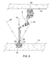
- figures 5 , 6 and 7 schematically show side views of the robotized system of Figure 1 with the treatment couch 5 in additional possible positions.
- FIGS 8 and 9 schematically show two side views of a second embodiment of a robotized system 1 according to the invention, which differs from that shown above in that one of the robotized arms, in the example the robotized arm 3, consists of a carriage 21, moveable along a linear guide 31 parallel to the linear guide 32, along which the other robotized arm 4 slides, and carries a jack 22 which, in turn carries a ball joint 23 to which an end of the treatment couch 5 is connected.
- the linear guide 31 is placed in an opening formed in the floor 11 of the room in which the robotized system 1 is installed.
- the linear guide 20 along which the robotized arm 3 moves is parallel to the guide 32, fixed to the ceiling 10 of the room in which the robotized system 1 is installed, along which the robotized arm 4 moves, but without departing from the scope of the invention, the guide 32 can be fixed to the floor 11 of the room in which the robotized system 1 is installed and the guide 31 can be fixed to the ceiling 10 of said room.
- a ball joint 23 allows cost reduction of the robotized system 1 but restricts the movement of the treatment couch 5 that, in the embodiment shown in Figures 8 and 9 , always remains in a substantially vertical position.
- the treatment couch 5 can rotate by 360° about the axis 41 passing through the end of the other robotized arm (4, 3), it can be vertically translated by the jack 22 and it can swing with respect to the axis 41 about the ball joint 23.
- the treatment couch 5 can therefore occupy any position within a cone having the vertex in the ball joint 23 and defined by the half-lines 42 and 43.
- the amplitude of the angle at the vertex of the cone depends on the characteristics of the ball joint 23; if the ball joint 23 allows a vertex angle of 180°, the cone becomes a hemisphere.
- the linear guide 31 which carries the carriage 21 may be placed within an opening formed in a side wall of the room in which the robotized system 1 is installed: in this case, the treatment couch 5 is in a substantially horizontal position and can rotate by 360° about the axis passing through the end of the other robotized arm (4, 3), it can be horizontally translated by the jack 22 and it can swing with respect to the axis 41 within a cone, having the vertex in the ball joint 23 and defined by half-lines 42 and 43.
- the amplitude of the angle at the vertex of such a cone depends on the characteristics of the ball joint 23: if the ball joint 23 allows a vertex angle of 180°, the cone becomes a hemisphere.
Landscapes
- Engineering & Computer Science (AREA)
- Health & Medical Sciences (AREA)
- Biomedical Technology (AREA)
- Robotics (AREA)
- Mechanical Engineering (AREA)
- Nuclear Medicine, Radiotherapy & Molecular Imaging (AREA)
- Life Sciences & Earth Sciences (AREA)
- Animal Behavior & Ethology (AREA)
- General Health & Medical Sciences (AREA)
- Public Health (AREA)
- Veterinary Medicine (AREA)
- Radiology & Medical Imaging (AREA)
- Pathology (AREA)
- Radiation-Therapy Devices (AREA)
- Accommodation For Nursing Or Treatment Tables (AREA)
- Manipulator (AREA)
Claims (10)
- Système robotisé (1) pour positionner un patient par rapport à au moins une source d'un faisceau de particules, comprenant au moins une source fixe d'un faisceau de particules pour la radiothérapie, deux bras robotisés (3, 4) et des guides linéaires respectifs (31, 32), un divan de traitement (5) pour le patient, chaque extrémité de celui-ci étant relié à l'extrémité desdits bras robotisés (3, 4) et une unité logique configurée pour contrôler et coordonner les mouvements des deux bras robotisés (3, 4), où- chaque bras robotisé (3, 4) est mobile le long du guide linéaire respectif (31, 32) configuré pour être fixé au sol (11), au plafond (10) ou à un mur de la pièce où le système robotisé (1) est installé, lesdits bras robotisés (3, 4) ayant six axes de rotation et un axe de translation horizontal,- ladite au moins une source est fixe et produit un faisceau de particules toujours compris dans l'espace entre les extrémités des deux bras robotisés (3, 4),- le divan de traitement (5) étant apte à être positionné dans toute position de l'espace comprise entre les deux bras robotisés (3, 4), et configure pour tourner axialement de 360° autour de la ligne joignant les extrémités des bras robotisés (3, 4).
- Système robotisé (1) selon la revendication 1, où les deux guides linéaires (31, 32) sont parallèles ou obliques l'un à l'autre.
- Système robotisé (1) selon la revendication 1 ou 2, où l'un des deux guides linéaires (31, 32) est configuré pour être fixé au sol (11) de la pièce où le système robotisé (1) est installé, tandis que l'autre guide linéaire (32, 31) est configuré pour être fixé au plafond (10) de ladite pièce.
- Système robotisé (1) selon la revendication 1 ou 2, où les deux guides linéaires (31, 32) sont configurés pour être fixés au plafond (10) ou au sol (11) de la pièce où le système robotisé (1) est installé.
- Système robotisé (1) selon la revendication 1, où le faisceau de particules est parallèle ou orthogonal aux guides linéaires (31, 32) ou incliné par rapport auxdits guides.
- Système robotisé (1) selon la revendication 1, où un des bras robotisés (3, 4) comprend un chariot (21) mobile le long d'un guide linéaire (31, 32) parallèle au guide linéaire (32, 31) le long duquel l'autre bras robotisé (4, 3) glisse, et ledit chariot (21) transporte un poussoir (22), qui à son tour transporte un joint à rotule (23) auquel une extrémité du divan de traitement (5) est reliée.
- Système robotisé (1) selon la revendication 6, où le guide linéaire le long duquel le chariot (21) glisse est placé dans un creux formé dans le sol (11), dans le plafond (10) ou dans un mur de la pièce où le système robotisé (1) est installé.
- Système robotisé (1) selon la revendication 6, où ledit divan de traitement (5) est configuré pour être translaté par le poussoir (22), et pour osciller autour du joint à rotule (23) par rapport à l'axe (41) passant par l'extrémité de l'autre bras robotisé, de manière à occuper toute position dans un cône ayant son sommet dans le joint à rotule (23).
- Système robotisé (1) selon la revendication 8, où ledit joint à rotule (23) autorise un angle au sommet de 180°C et où le divan de traitement (5) est apte à occuper toute position dans une demi-sphère ayant son sommet dans le joint à rotule (23).
- Système robotisé (1) selon l'une quelconque des revendications précédentes, où le divan de traitement (5) assure un siège intégrant audit divan de traitement (5).
Priority Applications (1)
| Application Number | Priority Date | Filing Date | Title |
|---|---|---|---|
| PL10169458T PL2279833T3 (pl) | 2009-07-28 | 2010-07-13 | Zrobotyzowany układ do pozycjonowania pacjenta w stosunku do źródła cząstek |
Applications Claiming Priority (1)
| Application Number | Priority Date | Filing Date | Title |
|---|---|---|---|
| ITMI2009A001344A IT1395114B1 (it) | 2009-07-28 | 2009-07-28 | Sistema robotizzato per il posizionamento di un paziente rispetto ad almeno una sorgente di particelle |
Publications (2)
| Publication Number | Publication Date |
|---|---|
| EP2279833A1 EP2279833A1 (fr) | 2011-02-02 |
| EP2279833B1 true EP2279833B1 (fr) | 2013-06-05 |
Family
ID=41467075
Family Applications (1)
| Application Number | Title | Priority Date | Filing Date |
|---|---|---|---|
| EP10169458.6A Active EP2279833B1 (fr) | 2009-07-28 | 2010-07-13 | Système robotisé de positionnement d'un patient par rapport à une source de particules |
Country Status (7)
| Country | Link |
|---|---|
| US (1) | US8449184B2 (fr) |
| EP (1) | EP2279833B1 (fr) |
| CN (1) | CN101985059B (fr) |
| DK (1) | DK2279833T3 (fr) |
| ES (1) | ES2427045T3 (fr) |
| IT (1) | IT1395114B1 (fr) |
| PL (1) | PL2279833T3 (fr) |
Families Citing this family (3)
| Publication number | Priority date | Publication date | Assignee | Title |
|---|---|---|---|---|
| US8584281B2 (en) * | 2011-04-07 | 2013-11-19 | Mizuho Orthopedic Systems, Inc | Surgery table having coordinated motion |
| DE102012223063A1 (de) * | 2012-12-13 | 2014-06-18 | Kuka Roboter Gmbh | Roboterarm |
| GB2535979A (en) * | 2015-02-05 | 2016-09-07 | Univ Bristol | Arrangement for machining a workpiece |
Family Cites Families (19)
| Publication number | Priority date | Publication date | Assignee | Title |
|---|---|---|---|---|
| CN1045345A (zh) * | 1989-03-06 | 1990-09-19 | 王化明 | 可调式手术依托器 |
| US6193142B1 (en) * | 1996-12-25 | 2001-02-27 | Nissan Motor Co., Ltd. | Assembling apparatus assembling body side of automotive vehicle and assembling method thereof |
| US6094760A (en) * | 1997-08-04 | 2000-08-01 | Sumitomo Heavy Industries, Ltd. | Bed system for radiation therapy |
| DE29909047U1 (de) * | 1999-05-22 | 2000-10-19 | Kuka Schweissanlagen Gmbh | Positioniervorrichtung für Werkstückträger oder Werkstücke |
| JP4678999B2 (ja) * | 2001-07-27 | 2011-04-27 | 株式会社東芝 | X線診断装置 |
| US20040133983A1 (en) * | 2003-01-13 | 2004-07-15 | Newkirk David C. | Surgical table |
| CZ13757U1 (cs) * | 2003-04-07 | 2003-10-21 | Daniševský Spol. S R.O. | Výškově přestavitelný instalační komplex pro zdravotnická pracoviště, zejména pro operační sály |
| KR101081839B1 (ko) * | 2003-08-12 | 2011-11-09 | 로마 린다 유니버시티 메디칼 센터 | 모듈러 환자 서포트 시스템 |
| CN1972732A (zh) * | 2004-02-05 | 2007-05-30 | 莫托里卡股份有限公司 | 康复锻炼和训练的方法和装置 |
| US8160205B2 (en) * | 2004-04-06 | 2012-04-17 | Accuray Incorporated | Robotic arm for patient positioning assembly |
| DE102004062473B4 (de) * | 2004-09-30 | 2006-11-30 | Siemens Ag | Medizinische Strahlentherapieanordnung |
| DE202004017881U1 (de) * | 2004-11-17 | 2006-03-23 | Kuka Schweissanlagen Gmbh | Handlingvorrichtung |
| US7152261B2 (en) * | 2005-02-22 | 2006-12-26 | Jackson Roger P | Modular multi-articulated patient support system |
| US7565708B2 (en) * | 2005-02-22 | 2009-07-28 | Jackson Roger P | Patient positioning support structure |
| US7983380B2 (en) * | 2005-04-29 | 2011-07-19 | Varian Medical Systems, Inc. | Radiation systems |
| DE102005041606B4 (de) * | 2005-09-01 | 2007-09-27 | Siemens Ag | Patientenpositioniervorrichtung für die Strahlentherapie |
| US7847275B2 (en) * | 2007-05-24 | 2010-12-07 | Pcure Ltd. | Method and apparatus for teletherapy positioning and validation |
| JP2010527683A (ja) * | 2007-05-24 | 2010-08-19 | ピー−キュアー リミテッド | 照射治療装置と方法 |
| DK2190530T3 (en) | 2007-09-13 | 2018-02-19 | Toby D Henderson | PATIENT POSITIONING SYSTEM |
-
2009
- 2009-07-28 IT ITMI2009A001344A patent/IT1395114B1/it active
-
2010
- 2010-07-13 PL PL10169458T patent/PL2279833T3/pl unknown
- 2010-07-13 EP EP10169458.6A patent/EP2279833B1/fr active Active
- 2010-07-13 DK DK10169458.6T patent/DK2279833T3/da active
- 2010-07-13 ES ES10169458T patent/ES2427045T3/es active Active
- 2010-07-14 US US12/836,100 patent/US8449184B2/en active Active
- 2010-07-28 CN CN201010243763.0A patent/CN101985059B/zh active Active
Also Published As
| Publication number | Publication date |
|---|---|
| US20110029129A1 (en) | 2011-02-03 |
| CN101985059B (zh) | 2015-04-01 |
| DK2279833T3 (da) | 2013-08-26 |
| US8449184B2 (en) | 2013-05-28 |
| ITMI20091344A1 (it) | 2011-01-29 |
| IT1395114B1 (it) | 2012-09-05 |
| EP2279833A1 (fr) | 2011-02-02 |
| CN101985059A (zh) | 2011-03-16 |
| PL2279833T3 (pl) | 2013-11-29 |
| ES2427045T3 (es) | 2013-10-28 |
Similar Documents
| Publication | Publication Date | Title |
|---|---|---|
| EP3089787B1 (fr) | Système pour une arcthérapie stéréotaxique à intensité modulée | |
| US8488739B2 (en) | Linear kinematics system with rotatable treatment head | |
| JP4289955B2 (ja) | アイソセンタ方式の粒子ビーム誘導用等速ガントリー装置およびその設計方法 | |
| JP4616843B2 (ja) | 多重室照射治療システム | |
| CN105126261B (zh) | 利用Stewart机器人平台进行跟踪定位的放疗装置 | |
| US11759659B2 (en) | Radiation therapy system | |
| CN105920746A (zh) | 一种放射治疗设备 | |
| CN203379504U (zh) | 一种适用于固定式强子束的360度治疗装置 | |
| CN105920745A (zh) | 放射治疗系统 | |
| EP2279833B1 (fr) | Système robotisé de positionnement d'un patient par rapport à une source de particules | |
| CN204619201U (zh) | 一种可实现全轨迹放射治疗设备 | |
| CN108042929B (zh) | 术中放射治疗装置 | |
| US20150248945A1 (en) | Apparatus to emit therapeutic radiations | |
| JP2014113419A (ja) | 粒子線治療装置 | |
| US20210161491A1 (en) | Adjustable support | |
| CN205084237U (zh) | 基于三自由度工作台的自适应放疗系统 | |
| CN116531680A (zh) | 直观高精度多轴运动机械臂 | |
| GB2592970A (en) | A radiotherapy apparatus for positioning a subject | |
| GB2586346A (en) | Beam delivery system with movement detection | |
| GB2587086A (en) | Beam delivery system | |
| GB2587085A (en) | Beam delivery system | |
| WO2016128255A1 (fr) | Appareil de radiothérapie |
Legal Events
| Date | Code | Title | Description |
|---|---|---|---|
| PUAI | Public reference made under article 153(3) epc to a published international application that has entered the european phase |
Free format text: ORIGINAL CODE: 0009012 |
|
| AK | Designated contracting states |
Kind code of ref document: A1 Designated state(s): AL AT BE BG CH CY CZ DE DK EE ES FI FR GB GR HR HU IE IS IT LI LT LU LV MC MK MT NL NO PL PT RO SE SI SK SM TR |
|
| AX | Request for extension of the european patent |
Extension state: BA ME RS |
|
| 17P | Request for examination filed |
Effective date: 20110630 |
|
| RIC1 | Information provided on ipc code assigned before grant |
Ipc: B25J 9/00 20060101AFI20121016BHEP |
|
| GRAP | Despatch of communication of intention to grant a patent |
Free format text: ORIGINAL CODE: EPIDOSNIGR1 |
|
| GRAS | Grant fee paid |
Free format text: ORIGINAL CODE: EPIDOSNIGR3 |
|
| GRAA | (expected) grant |
Free format text: ORIGINAL CODE: 0009210 |
|
| AK | Designated contracting states |
Kind code of ref document: B1 Designated state(s): AL AT BE BG CH CY CZ DE DK EE ES FI FR GB GR HR HU IE IS IT LI LT LU LV MC MK MT NL NO PL PT RO SE SI SK SM TR |
|
| REG | Reference to a national code |
Ref country code: GB Ref legal event code: FG4D |
|
| REG | Reference to a national code |
Ref country code: CH Ref legal event code: EP |
|
| REG | Reference to a national code |
Ref country code: AT Ref legal event code: REF Ref document number: 615366 Country of ref document: AT Kind code of ref document: T Effective date: 20130615 |
|
| REG | Reference to a national code |
Ref country code: IE Ref legal event code: FG4D |
|
| REG | Reference to a national code |
Ref country code: DE Ref legal event code: R096 Ref document number: 602010007506 Country of ref document: DE Effective date: 20130801 |
|
| REG | Reference to a national code |
Ref country code: DE Ref legal event code: R082 Ref document number: 602010007506 Country of ref document: DE Representative=s name: TBK, DE |
|
| REG | Reference to a national code |
Ref country code: CH Ref legal event code: NV Representative=s name: BOHEST AG, CH |
|
| REG | Reference to a national code |
Ref country code: DK Ref legal event code: T3 |
|
| REG | Reference to a national code |
Ref country code: SE Ref legal event code: TRGR |
|
| REG | Reference to a national code |
Ref country code: NL Ref legal event code: T3 |
|
| REG | Reference to a national code |
Ref country code: ES Ref legal event code: FG2A Ref document number: 2427045 Country of ref document: ES Kind code of ref document: T3 Effective date: 20131028 |
|
| PG25 | Lapsed in a contracting state [announced via postgrant information from national office to epo] |
Ref country code: LT Free format text: LAPSE BECAUSE OF FAILURE TO SUBMIT A TRANSLATION OF THE DESCRIPTION OR TO PAY THE FEE WITHIN THE PRESCRIBED TIME-LIMIT Effective date: 20130605 Ref country code: NO Free format text: LAPSE BECAUSE OF FAILURE TO SUBMIT A TRANSLATION OF THE DESCRIPTION OR TO PAY THE FEE WITHIN THE PRESCRIBED TIME-LIMIT Effective date: 20130905 Ref country code: SI Free format text: LAPSE BECAUSE OF FAILURE TO SUBMIT A TRANSLATION OF THE DESCRIPTION OR TO PAY THE FEE WITHIN THE PRESCRIBED TIME-LIMIT Effective date: 20130605 Ref country code: GR Free format text: LAPSE BECAUSE OF FAILURE TO SUBMIT A TRANSLATION OF THE DESCRIPTION OR TO PAY THE FEE WITHIN THE PRESCRIBED TIME-LIMIT Effective date: 20130906 |
|
| REG | Reference to a national code |
Ref country code: LT Ref legal event code: MG4D |
|
| PG25 | Lapsed in a contracting state [announced via postgrant information from national office to epo] |
Ref country code: HR Free format text: LAPSE BECAUSE OF FAILURE TO SUBMIT A TRANSLATION OF THE DESCRIPTION OR TO PAY THE FEE WITHIN THE PRESCRIBED TIME-LIMIT Effective date: 20130605 Ref country code: BG Free format text: LAPSE BECAUSE OF FAILURE TO SUBMIT A TRANSLATION OF THE DESCRIPTION OR TO PAY THE FEE WITHIN THE PRESCRIBED TIME-LIMIT Effective date: 20130905 |
|
| REG | Reference to a national code |
Ref country code: PL Ref legal event code: T3 |
|
| PG25 | Lapsed in a contracting state [announced via postgrant information from national office to epo] |
Ref country code: LV Free format text: LAPSE BECAUSE OF FAILURE TO SUBMIT A TRANSLATION OF THE DESCRIPTION OR TO PAY THE FEE WITHIN THE PRESCRIBED TIME-LIMIT Effective date: 20130605 |
|
| PG25 | Lapsed in a contracting state [announced via postgrant information from national office to epo] |
Ref country code: EE Free format text: LAPSE BECAUSE OF FAILURE TO SUBMIT A TRANSLATION OF THE DESCRIPTION OR TO PAY THE FEE WITHIN THE PRESCRIBED TIME-LIMIT Effective date: 20130605 Ref country code: SK Free format text: LAPSE BECAUSE OF FAILURE TO SUBMIT A TRANSLATION OF THE DESCRIPTION OR TO PAY THE FEE WITHIN THE PRESCRIBED TIME-LIMIT Effective date: 20130605 Ref country code: PT Free format text: LAPSE BECAUSE OF FAILURE TO SUBMIT A TRANSLATION OF THE DESCRIPTION OR TO PAY THE FEE WITHIN THE PRESCRIBED TIME-LIMIT Effective date: 20131007 Ref country code: CZ Free format text: LAPSE BECAUSE OF FAILURE TO SUBMIT A TRANSLATION OF THE DESCRIPTION OR TO PAY THE FEE WITHIN THE PRESCRIBED TIME-LIMIT Effective date: 20130605 Ref country code: IS Free format text: LAPSE BECAUSE OF FAILURE TO SUBMIT A TRANSLATION OF THE DESCRIPTION OR TO PAY THE FEE WITHIN THE PRESCRIBED TIME-LIMIT Effective date: 20131005 |
|
| PG25 | Lapsed in a contracting state [announced via postgrant information from national office to epo] |
Ref country code: RO Free format text: LAPSE BECAUSE OF FAILURE TO SUBMIT A TRANSLATION OF THE DESCRIPTION OR TO PAY THE FEE WITHIN THE PRESCRIBED TIME-LIMIT Effective date: 20130605 |
|
| PG25 | Lapsed in a contracting state [announced via postgrant information from national office to epo] |
Ref country code: MC Free format text: LAPSE BECAUSE OF FAILURE TO SUBMIT A TRANSLATION OF THE DESCRIPTION OR TO PAY THE FEE WITHIN THE PRESCRIBED TIME-LIMIT Effective date: 20130605 |
|
| PLBE | No opposition filed within time limit |
Free format text: ORIGINAL CODE: 0009261 |
|
| STAA | Information on the status of an ep patent application or granted ep patent |
Free format text: STATUS: NO OPPOSITION FILED WITHIN TIME LIMIT |
|
| 26N | No opposition filed |
Effective date: 20140306 |
|
| REG | Reference to a national code |
Ref country code: DE Ref legal event code: R097 Ref document number: 602010007506 Country of ref document: DE Effective date: 20140306 |
|
| REG | Reference to a national code |
Ref country code: CH Ref legal event code: PCAR Free format text: NEW ADDRESS: HOLBEINSTRASSE 36-38, 4051 BASEL (CH) |
|
| PG25 | Lapsed in a contracting state [announced via postgrant information from national office to epo] |
Ref country code: SM Free format text: LAPSE BECAUSE OF FAILURE TO SUBMIT A TRANSLATION OF THE DESCRIPTION OR TO PAY THE FEE WITHIN THE PRESCRIBED TIME-LIMIT Effective date: 20130605 |
|
| PG25 | Lapsed in a contracting state [announced via postgrant information from national office to epo] |
Ref country code: TR Free format text: LAPSE BECAUSE OF FAILURE TO SUBMIT A TRANSLATION OF THE DESCRIPTION OR TO PAY THE FEE WITHIN THE PRESCRIBED TIME-LIMIT Effective date: 20130605 Ref country code: CY Free format text: LAPSE BECAUSE OF FAILURE TO SUBMIT A TRANSLATION OF THE DESCRIPTION OR TO PAY THE FEE WITHIN THE PRESCRIBED TIME-LIMIT Effective date: 20130605 Ref country code: MT Free format text: LAPSE BECAUSE OF FAILURE TO SUBMIT A TRANSLATION OF THE DESCRIPTION OR TO PAY THE FEE WITHIN THE PRESCRIBED TIME-LIMIT Effective date: 20130605 |
|
| PG25 | Lapsed in a contracting state [announced via postgrant information from national office to epo] |
Ref country code: HU Free format text: LAPSE BECAUSE OF FAILURE TO SUBMIT A TRANSLATION OF THE DESCRIPTION OR TO PAY THE FEE WITHIN THE PRESCRIBED TIME-LIMIT; INVALID AB INITIO Effective date: 20100713 Ref country code: LU Free format text: LAPSE BECAUSE OF NON-PAYMENT OF DUE FEES Effective date: 20130713 Ref country code: MK Free format text: LAPSE BECAUSE OF FAILURE TO SUBMIT A TRANSLATION OF THE DESCRIPTION OR TO PAY THE FEE WITHIN THE PRESCRIBED TIME-LIMIT Effective date: 20130605 |
|
| REG | Reference to a national code |
Ref country code: FR Ref legal event code: PLFP Year of fee payment: 6 |
|
| REG | Reference to a national code |
Ref country code: FR Ref legal event code: PLFP Year of fee payment: 7 |
|
| REG | Reference to a national code |
Ref country code: FR Ref legal event code: PLFP Year of fee payment: 8 |
|
| REG | Reference to a national code |
Ref country code: FR Ref legal event code: PLFP Year of fee payment: 9 |
|
| PG25 | Lapsed in a contracting state [announced via postgrant information from national office to epo] |
Ref country code: AL Free format text: LAPSE BECAUSE OF FAILURE TO SUBMIT A TRANSLATION OF THE DESCRIPTION OR TO PAY THE FEE WITHIN THE PRESCRIBED TIME-LIMIT Effective date: 20130605 |
|
| REG | Reference to a national code |
Ref country code: FI Ref legal event code: PCE Owner name: LINEARBEAM S.R.L. |
|
| REG | Reference to a national code |
Ref country code: CH Ref legal event code: PK Free format text: RETTIFICHE |
|
| REG | Reference to a national code |
Ref country code: DE Ref legal event code: R081 Ref document number: 602010007506 Country of ref document: DE Owner name: LINEARBEAM S.R.L., IT Free format text: FORMER OWNER: ITEL TELECOMMUNICAZIONI S.R.L., RUVO DI PUGLIA, IT |
|
| REG | Reference to a national code |
Ref country code: GB Ref legal event code: 732E Free format text: REGISTERED BETWEEN 20211125 AND 20211201 |
|
| REG | Reference to a national code |
Ref country code: BE Ref legal event code: PD Owner name: LINEARBEAM S.R.L.; IT Free format text: DETAILS ASSIGNMENT: CHANGE OF OWNER(S), ASSIGNMENT; FORMER OWNER NAME: ITEL TELECOMUNICAZIONI S.R.L. Effective date: 20211108 |
|
| REG | Reference to a national code |
Ref country code: ES Ref legal event code: PC2A Owner name: LINEARBEAM, S.R.L. Effective date: 20220110 |
|
| REG | Reference to a national code |
Ref country code: NL Ref legal event code: PD Owner name: LINEARBEAM S.R.L.; IT Free format text: DETAILS ASSIGNMENT: CHANGE OF OWNER(S), ASSIGNMENT; FORMER OWNER NAME: ITEL TELECOMUNICAZIONI S.R.L. Effective date: 20211220 |
|
| REG | Reference to a national code |
Ref country code: AT Ref legal event code: PC Ref document number: 615366 Country of ref document: AT Kind code of ref document: T Owner name: LINEARBEAM S.R.L., IT Effective date: 20220107 |
|
| P01 | Opt-out of the competence of the unified patent court (upc) registered |
Effective date: 20230526 |
|
| PGFP | Annual fee paid to national office [announced via postgrant information from national office to epo] |
Ref country code: IT Payment date: 20230614 Year of fee payment: 14 Ref country code: IE Payment date: 20230630 Year of fee payment: 14 |
|
| PGFP | Annual fee paid to national office [announced via postgrant information from national office to epo] |
Ref country code: PL Payment date: 20230615 Year of fee payment: 14 Ref country code: NL Payment date: 20230726 Year of fee payment: 14 Ref country code: FI Payment date: 20230615 Year of fee payment: 14 |
|
| PGFP | Annual fee paid to national office [announced via postgrant information from national office to epo] |
Ref country code: GB Payment date: 20230615 Year of fee payment: 14 Ref country code: ES Payment date: 20230824 Year of fee payment: 14 Ref country code: CH Payment date: 20230801 Year of fee payment: 14 Ref country code: AT Payment date: 20230726 Year of fee payment: 14 |
|
| PGFP | Annual fee paid to national office [announced via postgrant information from national office to epo] |
Ref country code: SE Payment date: 20230719 Year of fee payment: 14 Ref country code: FR Payment date: 20230725 Year of fee payment: 14 Ref country code: DK Payment date: 20230728 Year of fee payment: 14 Ref country code: DE Payment date: 20230727 Year of fee payment: 14 Ref country code: BE Payment date: 20230726 Year of fee payment: 14 |