EP2279795A1 - Système de distribution d'un produit fluide - Google Patents
Système de distribution d'un produit fluide Download PDFInfo
- Publication number
- EP2279795A1 EP2279795A1 EP10290423A EP10290423A EP2279795A1 EP 2279795 A1 EP2279795 A1 EP 2279795A1 EP 10290423 A EP10290423 A EP 10290423A EP 10290423 A EP10290423 A EP 10290423A EP 2279795 A1 EP2279795 A1 EP 2279795A1
- Authority
- EP
- European Patent Office
- Prior art keywords
- chamber
- product
- distribution
- insert
- push button
- Prior art date
- Legal status (The legal status is an assumption and is not a legal conclusion. Google has not performed a legal analysis and makes no representation as to the accuracy of the status listed.)
- Granted
Links
Images
Classifications
-
- B—PERFORMING OPERATIONS; TRANSPORTING
- B65—CONVEYING; PACKING; STORING; HANDLING THIN OR FILAMENTARY MATERIAL
- B65D—CONTAINERS FOR STORAGE OR TRANSPORT OF ARTICLES OR MATERIALS, e.g. BAGS, BARRELS, BOTTLES, BOXES, CANS, CARTONS, CRATES, DRUMS, JARS, TANKS, HOPPERS, FORWARDING CONTAINERS; ACCESSORIES, CLOSURES, OR FITTINGS THEREFOR; PACKAGING ELEMENTS; PACKAGES
- B65D83/00—Containers or packages with special means for dispensing contents
- B65D83/14—Containers for dispensing liquid or semi-liquid contents by internal gaseous pressure, i.e. aerosol containers comprising propellant
- B65D83/75—Aerosol containers not provided for in groups B65D83/16 - B65D83/74
- B65D83/753—Aerosol containers not provided for in groups B65D83/16 - B65D83/74 characterised by details or accessories associated with outlets
-
- B—PERFORMING OPERATIONS; TRANSPORTING
- B05—SPRAYING OR ATOMISING IN GENERAL; APPLYING FLUENT MATERIALS TO SURFACES, IN GENERAL
- B05B—SPRAYING APPARATUS; ATOMISING APPARATUS; NOZZLES
- B05B11/00—Single-unit hand-held apparatus in which flow of contents is produced by the muscular force of the operator at the moment of use
- B05B11/01—Single-unit hand-held apparatus in which flow of contents is produced by the muscular force of the operator at the moment of use characterised by the means producing the flow
- B05B11/06—Gas or vapour producing the flow, e.g. from a compressible bulb or air pump
-
- B—PERFORMING OPERATIONS; TRANSPORTING
- B05—SPRAYING OR ATOMISING IN GENERAL; APPLYING FLUENT MATERIALS TO SURFACES, IN GENERAL
- B05B—SPRAYING APPARATUS; ATOMISING APPARATUS; NOZZLES
- B05B11/00—Single-unit hand-held apparatus in which flow of contents is produced by the muscular force of the operator at the moment of use
- B05B11/01—Single-unit hand-held apparatus in which flow of contents is produced by the muscular force of the operator at the moment of use characterised by the means producing the flow
- B05B11/10—Pump arrangements for transferring the contents from the container to a pump chamber by a sucking effect and forcing the contents out through the dispensing nozzle
- B05B11/1087—Combination of liquid and air pumps
-
- B—PERFORMING OPERATIONS; TRANSPORTING
- B05—SPRAYING OR ATOMISING IN GENERAL; APPLYING FLUENT MATERIALS TO SURFACES, IN GENERAL
- B05B—SPRAYING APPARATUS; ATOMISING APPARATUS; NOZZLES
- B05B11/00—Single-unit hand-held apparatus in which flow of contents is produced by the muscular force of the operator at the moment of use
- B05B11/01—Single-unit hand-held apparatus in which flow of contents is produced by the muscular force of the operator at the moment of use characterised by the means producing the flow
- B05B11/10—Pump arrangements for transferring the contents from the container to a pump chamber by a sucking effect and forcing the contents out through the dispensing nozzle
- B05B11/1097—Pump arrangements for transferring the contents from the container to a pump chamber by a sucking effect and forcing the contents out through the dispensing nozzle with means for sucking back the liquid or other fluent material in the nozzle after a dispensing stroke
-
- B—PERFORMING OPERATIONS; TRANSPORTING
- B05—SPRAYING OR ATOMISING IN GENERAL; APPLYING FLUENT MATERIALS TO SURFACES, IN GENERAL
- B05B—SPRAYING APPARATUS; ATOMISING APPARATUS; NOZZLES
- B05B11/00—Single-unit hand-held apparatus in which flow of contents is produced by the muscular force of the operator at the moment of use
- B05B11/01—Single-unit hand-held apparatus in which flow of contents is produced by the muscular force of the operator at the moment of use characterised by the means producing the flow
- B05B11/10—Pump arrangements for transferring the contents from the container to a pump chamber by a sucking effect and forcing the contents out through the dispensing nozzle
- B05B11/1042—Components or details
- B05B11/1043—Sealing or attachment arrangements between pump and container
- B05B11/1046—Sealing or attachment arrangements between pump and container the pump chamber being arranged substantially coaxially to the neck of the container
- B05B11/1047—Sealing or attachment arrangements between pump and container the pump chamber being arranged substantially coaxially to the neck of the container the pump being preassembled as an independent unit before being mounted on the container
-
- B—PERFORMING OPERATIONS; TRANSPORTING
- B05—SPRAYING OR ATOMISING IN GENERAL; APPLYING FLUENT MATERIALS TO SURFACES, IN GENERAL
- B05B—SPRAYING APPARATUS; ATOMISING APPARATUS; NOZZLES
- B05B7/00—Spraying apparatus for discharge of liquids or other fluent materials from two or more sources, e.g. of liquid and air, of powder and gas
- B05B7/02—Spray pistols; Apparatus for discharge
- B05B7/06—Spray pistols; Apparatus for discharge with at least one outlet orifice surrounding another approximately in the same plane
- B05B7/062—Spray pistols; Apparatus for discharge with at least one outlet orifice surrounding another approximately in the same plane with only one liquid outlet and at least one gas outlet
- B05B7/065—Spray pistols; Apparatus for discharge with at least one outlet orifice surrounding another approximately in the same plane with only one liquid outlet and at least one gas outlet an inner gas outlet being surrounded by an annular adjacent liquid outlet
-
- B—PERFORMING OPERATIONS; TRANSPORTING
- B05—SPRAYING OR ATOMISING IN GENERAL; APPLYING FLUENT MATERIALS TO SURFACES, IN GENERAL
- B05B—SPRAYING APPARATUS; ATOMISING APPARATUS; NOZZLES
- B05B7/00—Spraying apparatus for discharge of liquids or other fluent materials from two or more sources, e.g. of liquid and air, of powder and gas
- B05B7/02—Spray pistols; Apparatus for discharge
- B05B7/10—Spray pistols; Apparatus for discharge producing a swirling discharge
Definitions
- the invention relates to a system for dispensing a fluid product comprising a device for sampling under pressure of said product, a sleeve and a push button for actuating said device which is mounted in translation relative to the sleeve on a dispensing stroke. / aspiration of the product.
- the invention also relates to a dispensing bottle comprising such a dispensing system.
- the dispensing system is intended to equip bottles used in perfumery, in cosmetics or for pharmaceutical treatments.
- this type of bottle contains a product which is returned under pressure by a pump or a manually operated valve by means of a push button which is arranged to allow the product to be sprayed.
- Such push buttons may include a body on which a tip is disposed around an insert so as to form a dispensing chamber between said tip and said insert.
- the distribution chamber is in upstream communication with a supply duct mounted on a pipe for supplying the pressurized product, said chamber comprising a downstream part provided with at least one distribution channel of the product in a zone of spray which is provided opposite the front end of the insert.
- the dispensing chamber comprises a vortex chamber in which the spray zone is formed.
- the vortex chamber is arranged to form an aerosol with the product by rotating it very rapidly to give it speed.
- the swirl chamber is extended at its center by a dispensing orifice, the product can escape at high speed by splitting into fine droplets forming the aerosol.
- the distribution channels of the chamber are each convergent towards an outlet orifice, said convergent channels being arranged to allow the impaction in the spray zone of the jets of liquid distributed by said orifices.
- the embodiments according to the prior art do not make it possible to guarantee the production of an aerosol of optimum quality, especially with regard to the fineness of the droplets comprising it.
- the kinetic energy of the product at the level of the spray zone is relatively low, which limits the speed as well as the dispensing distance of the aerosol relative to the push button.
- the product remains present in the vicinity of the spraying zone, said product residue can then flow between two distributions on the outside of the push button.
- the invention aims to improve the prior art by proposing in particular a system for dispensing, at greater speed and at a greater distance from the push button, an aerosol formed by fine droplets, while avoiding that a remainder of product can flow between two distributions on said push button so in particular to limit the risk of contamination of said product.
- the invention proposes a system for dispensing a fluid product comprising a device for sampling under pressure of said product and a sleeve, said system further comprising a push button for actuating said device which is mounted in translation relative to the sleeve over a dispensing / suction stroke of the product, said push button comprising a body on which a nozzle is disposed around an insert so as to form a dispensing chamber between said nozzle and said insert, said distribution chamber being in upstream communication with a supply duct mounted on a tube for feeding the product under pressure, said chamber comprising a downstream part provided with at least one product distribution channel in a spray zone which is expected facing the front end of the insert, the insert having an internal chamber which opens into an orifice formed in the front end of said insert facing the central part of the spray zone, said internal chamber being in communication with a piston chamber which is formed between the body of the push button and the sleeve, said piston chamber having a variable volume depending
- the invention proposes a dispensing bottle of a fluid product comprising a container for packaging said product and such a dispensing system which is mounted on the reservoir so as to allow the dispensing of said product by actuation of the push button.
- a system for dispensing a pressurized fluid product is described below, said product being of any kind, especially used in perfumery, in cosmetics or for pharmaceutical treatments.
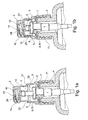
- the dispensing system comprises a sampling device 1 under liquid pressure which is manually actuated by means of a pushbutton 2.
- the sampling device 1 may comprise a pump as shown in FIGS. figures 1 or a valve in the case where the liquid is packaged under pressure.
- the push button 2 is mounted on a feed tube 3 of the pressurized product coming from the pump 1, the dispensing system being mounted on the neck 4 of a bottle comprising a product conditioning tank so as to feed the push button 2 with said product under pressure.
- the dispensing system further comprises a sleeve 5 which can be made integrally ductile material, especially polyolefin plastic material.
- the push button 2 is mounted in translation relative to the sleeve 5 on a dispensing / suction stroke of the product.
- the sleeve 5 has a chimney 6 in which are positioned means for securing the pump 1.
- an association armature 7 of the pump 1 is formed in the chimney 6 to make said pump secured to the sleeve 5.
- the sleeve 5 can be integrated in the body of the pump 1, for example by forming a stent for said pump.
- the sleeve 5 may be devoid of means for fixing the pump 1 on the neck 4, said pump can then be directly sealed inside said neck.
- association armature 7 comprises an orifice 8 in which the pump 1 is mounted with the delivery tube 3 which extends in the chimney 6, said armature further comprising a latching groove 9 of a bead 10 formed on the body of the pump 1.
- the sleeve 5 also has a lower skirt 11 which extends axially from one piece under the chimney 6, said skirt being provided with means for fixing said sleeve on the neck 4 of the bottle.
- the skirt 11 is provided with an internal screw thread to enable it to be screwed onto the threaded neck 4 of the bottle.
- the skirt 11 may be deformable between a mounting configuration in which said skirt is positionable around the neck 4 and a clamping configuration of said skirt around said neck to secure.
- the push button 2 comprises a body having an annular skirt 12 surrounding a housing 13 for mounting on the feed tube 3 of the pressurized product. Furthermore, the push button 2 comprises an upper zone 14 allowing the user to exert a digital support on said push button in order to be able to move it axially on its dispensing stroke to actuate the sampling device 1, the return of the button pusher 2 on its suction stroke being conventionally performed by an elastic return means.
- the push button 2 also comprises a tip 15 which is disposed around an insert 16 so as to form a distribution chamber 17 between said tip and said insert.
- the distribution chamber 17 is formed at the interface between an inner wall of the nozzle 15 and an outer wall of the insert 16, a hollow recess being formed on at least one of said walls so as to be closed by the other wall delimiting said chamber.
- the body of the push button 2 has a housing 18 in which the insert 16 is arranged to allow lateral spraying of the product relative to the body of said push button. More specifically, the skirt 12 is carried by a disc 19 of the body of the button pusher 2, said disc lower delimiting the upper housing 18 in which the insert 16 is disposed.
- the insert 16 can be associated sealingly in the housing 18. Alternatively, it may be integral with the body of the push button 2.
- the outer wall of the tip 15 has an anchor rod 15a in the wall of the housing 18 so as to allow the sealed association of said tip in said housing.
- the tip 15 may be formed around the insert 16.
- the distribution chamber 17 is in upstream communication with a supply conduit 20 which opens into the housing 13 for mounting on the feed tube 3 of the pressurized product.
- the supply duct 20 comprises an upstream portion 20a coaxial with the housing 13 and a downstream portion 20b formed around the insert 16.
- the distribution chamber 17 comprises a downstream part provided with at least one distribution channel 21 of the product in a spraying zone 22 which is provided opposite the front end 23 of the insert 16.
- a spraying zone 22 which is provided opposite the front end 23 of the insert 16.
- an aerosol of the product is formed to be dispensed in front of the front end 23 of the insert 16.
- the insert 16 also has an internal chamber 24 which opens into an orifice 25 formed in the front end 23 of said insert facing the central part of the spraying zone 22.
- the insert 16 presents a bore in which the inner chamber 24 is formed, said bore opening into the orifice 25 formed in the front end 23.
- the inner chamber 24 is in communication with a piston chamber 26 which is formed between the body of the push button 2 and the sleeve 5, said piston chamber having a variable volume depending on the position of the pushbutton 2 relative to the sleeve 5 so as to inject the air in - respectively sucking air from - the inner chamber 24 and therefore the central portion of the spray zone 22 on the distribution stroke - suction respectively - of said push button.
- the internal chamber 24 can be convergent toward the orifice 25 so as to allow an acceleration of the air flow injected into the spraying area 22.
- the bore has a frustoconical front portion 24a which opens into the front orifice 25.
- the skirt 12 is slidably mounted in the chimney 6 so as to form the piston chamber 26 between said skirt and said chamber.
- the volume of the piston chamber 26 decreases - respectively increases - on the distribution stroke - suction respectively - of the push button 2.
- the piston chamber 26 is delimited, tightly, laterally by the skirt 12 and the chimney 6 to have a variable axial dimension, superiorly by the disk 19 and inferiorly by the association armature 7 in the orifice 8 of which the pump 1 is associated tightly.
- the communication between the internal chamber 24 and the piston chamber 26 is carried out via an orifice 27 provided in the disc 19, said orifice communicating with the rear opening 28 of the bore in which the chamber internal 24 is formed.
- the bottom of the housing 18 is provided with an inclined face 29 forming a space for communication between the orifice 27 and the rear opening 28.
- the sealing of the piston chamber 26 is achieved by providing that the lower end portion of the skirt 12 has a sealing ring 30 which is sealingly mounted against the chimney 6.
- the chimney 6 has an upper chamfer 31 for engagement of the rod 30 in leaktight sliding in the chimney 6, said engagement being able to induce a radial clamping of the rod 30 against said chimney so as to make the conferred sealing more reliable.
- the outer diameter of the rod 30 may be slightly greater than the inside diameter of the chimney 6, said chimney being then placed in elastic stress on the rod 30 during its engagement.
- the embodiment shown provides that, when the pushbutton 2 is in its idle state ( figure 1a ), the piston chamber 26 is open. To do this, the distribution / suction stroke may be provided slightly longer than the sliding stroke of the rod 30 in the chimney 6, so as to leave an open passage 32 in the rest position.
- the distribution chamber 17 comprises a swirl chamber in which the spraying area 22 is formed, said chamber being provided with a dispensing orifice which is coaxial with the orifice 25 of the internal chamber 24. in addition to rotating the product, the aerosol is formed by blowing the product through the dispensing orifice.
- the distribution chamber 17 comprises distribution channels 21 each converging towards an outlet orifice 21a, said convergent channels being arranged to allow impaction in the central part of the spray zone 22 of the jets of product distributed by said orifices.
- the insert 16 has a base 34 of tight association in the housing 18 on which extends a rod 35 around which the distribution chamber 17 is formed.
- the downstream part 20b of feed duct 20 opens at the junction between the base 34 and the rod 35, said downstream portion of said feed duct being formed around said rod.
- the distribution chamber 17 presents, successively in communication, upstream channels 36, downstream channels 37 and distribution channels 21, said upstream and downstream channels extend longitudinally forming a section respectively upstream and downstream of the product flow in the
- the upstream and downstream sections correspond to the sum of the sections of the respectively upstream 36 and downstream 37 channels.
- the downstream section may be smaller than the size of the upstream section.
- the speed of the product increases from upstream to downstream so as to feed the convergent channels 21 with a flow of product whose speed is important.
- the rod 35 shown comprises grooves 38 which are closed by the inner wall of revolution of the nozzle 15 so as to form the channels 36, 37, 21.
- the rod 35 has a distal tip 39 of reduced diameter, on which the downstream section is formed, the inner wall of the end piece 15 having a complementary geometry to allow the tight fitting of said endpiece around the rod 35.
- each groove 38 has a frustoconical geometry which is arranged to form a distribution channel 21.
- the distribution channels 21, for example three in number, are very small, for example about 60 ⁇ m wide. and depth 70 ⁇ m for a device for sampling a dose of 100 ⁇ l under a pressure of 5 bar.
- the tip 15 has a seat 40 in which the front end 23 of the insert 16 is disposed in abutment, said seat and said end each having a frustoconical geometry so as to form the distribution channels 21 and the orifices output 21a between said geometries.
- the distribution channels 21 have a decreasing section from upstream to downstream.
- the tip 15 shown comprises a front extension 41 in the rear portion of which the seat 40 is formed.
- the extension 41 has a bore 42 which is coaxial with the bore 24 and its orifice 25, at least a portion of the spray zone 22 being housed in said bore.
- the extension 41 protrudes from the housing 18 and the body of the pushbutton 2 ( figure 3 ).
- the tip 15 is disposed around the insert 16 while being adjacent to the push button 2, for example in the case where the upstream portion 20a is aligned with the downstream portion 20b for a spray nozzle.
Landscapes
- Chemical & Material Sciences (AREA)
- Dispersion Chemistry (AREA)
- Engineering & Computer Science (AREA)
- Mechanical Engineering (AREA)
- Containers And Packaging Bodies Having A Special Means To Remove Contents (AREA)
Abstract
Description
- L'invention concerne un système de distribution d'un produit fluide comprenant un dispositif de prélèvement sous pression dudit produit, un manchon ainsi qu'un bouton poussoir d'actionnement dudit dispositif qui est monté en translation par rapport au manchon sur une course de distribution / aspiration du produit. L'invention concerne également un flacon de distribution comprenant un tel système de distribution.
- Dans une application particulière, le système de distribution est destiné à équiper des flacons utilisés en parfumerie, en cosmétique ou pour des traitements pharmaceutiques. En effet, ce type de flacon contient un produit qui est restitué sous pression par une pompe ou une valve à actionnement manuel au moyen d'un bouton poussoir qui est agencé pour permettre la pulvérisation du produit.
- De tels boutons poussoirs peuvent comprendre un corps sur lequel un embout est disposé autour d'un insert de sorte à former une chambre de distribution entre ledit embout et ledit insert. En particulier, la chambre de distribution est en communication amont avec un conduit d'alimentation monté sur un tube d'amenée du produit sous pression, ladite chambre comprenant une partie aval pourvue d'au moins un canal de distribution du produit dans une zone de pulvérisation qui est prévue en regard de l'extrémité avant de l'insert.
- Selon une réalisation, la chambre de distribution comprend une chambre tourbillonnaire dans laquelle est formée la zone de pulvérisation. En particulier, la chambre tourbillonnaire est agencée pour former un aérosol avec le produit en le faisant tourner très rapidement afin de lui donner de la vitesse. Ainsi, en prévoyant que la chambre tourbillonnaire soit prolongée en son centre par un orifice de distribution, le produit peut s'échapper à forte vitesse en se fractionnant en fines gouttelettes formant l'aérosol.
- Selon une autre réalisation, les canaux de distribution de la chambre sont convergents chacun vers un orifice de sortie, lesdits canaux convergents étant agencés pour permettre l'impaction dans la zone de pulvérisation des jets de liquide distribués par lesdits orifices. Ainsi, lors de l'impaction des jets distribués à grande vitesse, il se forme un aérosol sans avoir recours à une chambre tourbillonnaire.
- Toutefois, les réalisations selon l'art antérieur ne permettent pas de garantir la réalisation d'un aérosol de qualité optimale, notamment relativement à la finesse des gouttelettes le composant. En outre, l'énergie cinétique du produit au niveau de la zone de pulvérisation est relativement faible, ce qui limite la vitesse ainsi que la distance de distribution de l'aérosol par rapport au bouton poussoir.
- Par ailleurs, en fin de distribution, du produit reste présent au voisinage de la zone de pulvérisation, ledit reste de produit pouvant alors couler entre deux distributions sur l'extérieur du bouton poussoir.
- L'invention vise à perfectionner l'art antérieur en proposant notamment un système permettant la distribution, à plus grande vitesse et à distance plus importante du bouton poussoir, d'un aérosol formé de gouttelettes fines, et ce en évitant qu'un reste de produit puisse couler entre deux distributions sur ledit bouton poussoir de sorte notamment à limiter les risques de contamination dudit produit.
- A cet effet, et selon un premier aspect, l'invention propose un système de distribution d'un produit fluide comprenant un dispositif de prélèvement sous pression dudit produit et un manchon, ledit système comprenant en outre un bouton poussoir d'actionnement dudit dispositif qui est monté en translation par rapport au manchon sur une course de distribution / aspiration du produit, ledit bouton poussoir comprenant un corps sur lequel un embout est disposé autour d'un insert de sorte à former une chambre de distribution entre ledit embout et ledit insert, ladite chambre de distribution étant en communication amont avec un conduit d'alimentation monté sur un tube d'amenée du produit sous pression, ladite chambre comprenant une partie aval pourvue d'au moins un canal de distribution du produit dans une zone de pulvérisation qui est prévue en regard de l'extrémité avant de l'insert, l'insert présentant une chambre interne qui débouche dans un orifice formé dans l'extrémité avant dudit insert en regard de la partie centrale de la zone de pulvérisation, ladite chambre interne étant en communication avec une chambre de piston qui est formée entre le corps du bouton poussoir et le manchon, ladite chambre de piston présentant un volume variable en fonction de la position du bouton poussoir par rapport au manchon de sorte à injecter de l'air dans - respectivement à aspirer de l'air depuis - la chambre interne et donc la partie centrale de la zone de pulvérisation sur la course de distribution - respectivement d'aspiration - dudit bouton poussoir.
- Selon un deuxième aspect, l'invention propose un flacon de distribution d'un produit fluide comprenant un réservoir de conditionnement dudit produit et un tel système de distribution qui est monté sur le réservoir de sorte à permettre la distribution dudit produit par actionnement du bouton poussoir.
- D'autres objets et avantages de l'invention apparaîtront dans la description qui suit, faite en référence aux figures annexées, dans lesquelles :
- les
figures 1 sont des vues partielles en coupe longitudinale d'un système de distribution selon l'invention qui est monté sur le col d'un flacon, dans lesquelles le bouton poussoir est respectivement dans un état au repos (figure 1a ) et en fin de course de distribution (figure 1b ) ; - la
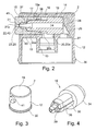
figure 2 est une vue en coupe longitudinale du bouton poussoir du système de distribution selon lesfigures 1 ; - la
figure 3 est une vue en perspective du bouton poussoir selon lafigure 2 ; - la
figure 4 est une vue en perspective de l'insert du bouton poussoir selon lafigure 2 . - En relation avec les figures, on décrit ci-dessous un système de distribution d'un produit fluide sous pression, ledit produit pouvant être de toute nature, notamment utilisé en parfumerie, en cosmétique ou pour des traitements pharmaceutiques.
- Le système de distribution comprend un dispositif de prélèvement 1 sous pression du liquide qui est actionné manuellement au moyen d'un bouton poussoir 2. En particulier, le dispositif de prélèvement 1 peut comprendre une pompe comme représentée sur les
figures 1 ou une valve dans le cas où le liquide est conditionné sous pression. - En relation avec les
figures 1 , le bouton poussoir 2 est monté sur un tube d'amenée 3 du produit sous pression provenant de la pompe 1, le système de distribution étant monté sur le col 4 d'un flacon comprenant un réservoir de conditionnement du produit de sorte à alimenter le bouton poussoir 2 avec ledit produit sous pression. - Pour assurer le positionnement et la fixation de la pompe 1 sur le col 4, le système de distribution comprend en outre un manchon 5 qui peut être réalisé de façon monobloc en matériau ductile, notamment en matière plastique de type polyoléfine. En particulier, le bouton poussoir 2 est monté en translation par rapport au manchon 5 sur une course de distribution / aspiration du produit.
- En partie supérieure, le manchon 5 présente une cheminée 6 dans laquelle sont positionnés des moyens de solidarisation de la pompe 1. Dans le mode de réalisation représenté, une armature d'association 7 de la pompe 1 est formée dans la cheminée 6 afin de rendre ladite pompe solidaire du manchon 5.
- En variante non représentée, le manchon 5 peut être intégré au corps de la pompe 1, par exemple en formant extenseur pour ladite pompe. Dans cette réalisation, le manchon 5 peut être dépourvu de moyen de fixation de la pompe 1 sur le col 4, ladite pompe pouvant alors être directement fixée étanche à l'intérieur dudit col.
- Dans le mode de réalisation représenté, l'armature d'association 7 comprend un orifice 8 dans lequel la pompe 1 est montée avec le tube d'amenée 3 qui s'étend dans la cheminée 6, ladite armature comprenant en outre une gorge d'encliquetage 9 d'un bourrelet 10 formé sur le corps de la pompe 1.
- Le manchon 5 présente égaiement une jupe inférieure 11 qui s'étend axialement d'une pièce sous la cheminée 6, ladite jupe étant pourvue de moyens de fixation dudit manchon sur le col 4 du flacon. Dans le mode de réalisation représenté, la jupe 11 est pourvue d'un pas de vis interne pour permettre son vissage sur le col 4 fileté du flacon. En variante, la jupe 11 peut être déformable entre une configuration de montage dans laquelle ladite jupe est positionnable autour du col 4 et une configuration de serrage de ladite jupe autour dudit col pour assurer la fixation.
- En relation avec la
figure 2 , le bouton poussoir 2 comprend un corps présentant une jupe annulaire 12 qui entoure un logement 13 de montage sur le tube d'amenée 3 du produit sous pression. Par ailleurs, le bouton poussoir 2 comprend une zone supérieure 14 permettant à l'utilisateur d'exercer un appui digital sur ledit bouton poussoir afin de pouvoir le déplacer axialement sur sa course de distribution pour actionner le dispositif de prélèvement 1, le retour du bouton poussoir 2 sur sa course d'aspiration étant classiquement réalisé par un moyen de rappel élastique. - Le bouton poussoir 2 comprend également un embout 15 qui est disposé autour d'un insert 16 de sorte à former une chambre de distribution 17 entre ledit embout et ledit insert. En particulier, la chambre de distribution 17 est formée à l'interface entre une paroi intérieure de l'embout 15 et une paroi extérieure de l'insert 16, une empreinte en creux étant formée sur au moins une desdites parois de sorte à être fermée par l'autre paroi en délimitant ladite chambre.
- Dans le mode de réalisation représenté, le corps du bouton poussoir 2 présente un logement 18 dans lequel l'insert 16 est disposé pour permettre une pulvérisation latérale du produit relativement au corps dudit bouton poussoir. Plus précisément, la jupe 12 est portée par un disque 19 du corps du bouton poussoir 2, ledit disque délimitant inférieurement le logement supérieur 18 dans lequel l'insert 16 est disposé.
- Comme représenté sur les figures, i'insert 16 peut être associé de façon étanche dans le logement 18. En variante, il peut être venu de matière avec le corps du bouton poussoir 2. Par ailleurs, la paroi extérieure de l'embout 15 présente un jonc d'ancrage 15a dans la paroi du logement 18 de sorte à permettre l'association étanche dudit embout dans ledit logement. En variante, notamment dans le cas d'un embout nasal, l'embout 15 peut être formé autour de l'insert 16.
- La chambre de distribution 17 est en communication amont avec un conduit d'alimentation 20 qui débouche dans le logement 13 de montage sur le tube d'amenée 3 du produit sous pression. Dans le mode de réalisation représenté, le conduit d'alimentation 20 comprend une partie amont 20a coaxiale au logement 13 et une partie aval 20b formée autour de l'insert 16.
- La chambre de distribution 17 comprend une partie aval pourvue d'au moins un canal de distribution 21 du produit dans une zone de pulvérisation 22 qui est prévue en regard de l'extrémité avant 23 de l'insert 16. En particulier, dans la zone de pulvérisation 22, un aérosol du produit est formé pour être distribué devant l'extrémité avant 23 de l'insert 16.
- L'insert 16 présente également une chambre interne 24 qui débouche dans un orifice 25 formé dans l'extrémité avant 23 dudit insert en regard de la partie centrale de la zone de pulvérisation 22. Dans le mode de réalisation représenté, l'insert 16 présente un alésage dans lequel la chambre interne 24 est formée, ledit alésage débouchant dans l'orifice 25 formé dans l'extrémité avant 23.
- Par ailleurs, la chambre interne 24 est en communication avec une chambre de piston 26 qui est formée entre le corps du bouton poussoir 2 et le manchon 5, ladite chambre de piston présentant un volume variable en fonction de la position du bouton poussoir 2 par rapport au manchon 5 de sorte à injecter de l'air dans - respectivement à aspirer de l'air depuis - la chambre interne 24 et donc la partie centrale de la zone de pulvérisation 22 sur la course de distribution - respectivement d'aspiration - dudit bouton poussoir.
- Ainsi, par injection d'air dans la partie centrale de la zone de pulvérisation 22 au travers de l'orifice 25 qui est en regard de ladite partie, il est possible de former un aérosol formé de gouttelettes fines, ledit aérosol étant en outre plus aérien puisqu'il est soufflé en son centre à distance du corps du bouton poussoir 2. Par ailleurs, l'aspiration conférée permet de renifler dans la chambre interne 24 le reste de produit qui est disposé dans la zone de pulvérisation 22 en fin de distribution.
- En particulier, la chambre interne 24 peut être convergente en direction de l'orifice 25 de sorte à permettre une accélération du flux d'air injecté dans la zone de pulvérisation 22. Sur les figures, l'alésage présente une partie avant tronconique 24a qui débouche dans l'orifice avant 25.
- Dans le mode de réalisation représenté, la jupe 12 est montée en coulissement étanche dans la cheminée 6 de sorte à former la chambre de piston 26 entre ladite jupe et ladite chambre. Ainsi, le volume de la chambre de piston 26 diminue - respectivement augmente - sur la course de distribution - respectivement d'aspiration - du bouton poussoir 2. Plus précisément, la chambre de piston 26 est délimitée, de façon étanche, latéralement par la jupe 12 et la cheminée 6 pour présenter une dimension axiale variable, supérieurement par le disque 19 et inférieurement par l'armature d'association 7 dans l'orifice 8 de laquelle la pompe 1 est associée de façon étanche.
- Par ailleurs, la communication entre la chambre interne 24 et la chambre de piston 26 est réalisée par l'intermédiaire d'un orifice 27 prévu dans le disque 19, ledit orifice communicant avec l'ouverture arrière 28 de l'alésage dans lequel la chambre interne 24 est formée. Pour ce faire, le fond du logement 18 est pourvu d'un pan incliné 29 formant un espace de mise en communication entre l'orifice 27 et l'ouverture arrière 28.
- L'étanchéité de la chambre de piston 26 est réalisée en prévoyant que la partie extrême inférieure de la jupe 12 présente un jonc d'étanchéité 30 qui est monté en coulissement étanche contre la cheminée 6. Dans le mode de réalisation représenté, la cheminée 6 présente un chanfrein supérieur 31 d'engagement du jonc 30 en coulissement étanche dans la cheminée 6, ledit engagement pouvant induire un serrage radial du jonc 30 contre ladite cheminée de sorte à fiabiliser l'étanchéité conférée. En particulier, le diamètre extérieur du jonc 30 peut être légèrement supérieur au diamètre intérieur de la cheminée 6, ladite cheminée étant alors mise en contrainte élastique sur le jonc 30 lors de son engagement.
- Le mode de réalisation représenté prévoit que, lorsque le bouton poussoir 2 est dans son état au repos (
figure 1a ), la chambre de piston 26 soit ouverte. Pour ce faire, la course de distribution / aspiration peut être prévue légèrement plus longue que la course de coulissement du jonc 30 dans la cheminée 6, de sorte à laisser un passage ouvert 32 en positon de repos. - Selon une réalisation non représentée, la chambre de distribution 17 comprend une chambre tourbillonnaire dans laquelle est formée la zone de pulvérisation 22, ladite chambre étant pourvue d'un orifice de distribution qui est coaxial avec l'orifice 25 de la chambre interne 24. Ainsi, outre la rotation du produit, l'aérosol est formé en soufflant sur le produit au travers de l'orifice de distribution.
- Dans le mode de réalisation représenté, la chambre de distribution 17 comprend des canaux de distribution 21 convergeant chacun vers un orifice de sortie 21 a, lesdits canaux convergents étant agencés pour permettre l'impaction dans la partie centrale de la zone de pulvérisation 22 des jets de produit distribués par lesdits orifices.
- En relation avec la
figure 4 , l'insert 16 présente une base 34 d'association étanche dans le logement 18 sur laquelle s'étend une tige 35 autour de laquelle la chambre de distribution 17 est formée. Par ailleurs, la partie aval 20b du conduit d'alimentation 20 débouche au niveau de la jonction entre la base 34 et la tige 35, ladite partie aval dudit conduit d'alimentation étant formée autour de ladite tige. - La chambre de distribution 17 présente, successivement en communication, des canaux amont 36, des canaux aval 37 et les canaux de distribution 21, lesdits canaux amont et aval s'étendent longitudinalement en formant une section respectivement amont et aval de circulation du produit dans la chambre de distribution 17. En particulier, les sections amont et aval correspondent à la somme des sections des canaux respectivement amont 36 et aval 37.
- Selon une réalisation, la section aval peut être de dimension inférieure à la dimension de la section amont. Ainsi, la vitesse du produit augmente depuis l'amont vers l'aval de sorte à pouvoir alimenter les canaux convergents 21 avec un flux de produit dont la vitesse est importante.
- La tige 35 représentée comprend des rainures 38 qui sont fermées par la paroi intérieure de révolution de l'embout 15 de sorte à former les canaux 36, 37, 21. En particulier, la tige 35 présente une pointe distale 39 de diamètre réduit, sur laquelle la section aval est formée, la paroi intérieure de l'embout 15 présentant une géométrie complémentaire pour permettre l'emmanchement étanche dudit embout autour de la tige 35.
- En outre, l'extrémité aval de chaque rainure 38 présente une géométrie tronconique qui est agencée pour former un canal de distribution 21. Les canaux de distribution 21, par exemple au nombre de trois, sont très petits, par exemple de largeur environ 60 µm et de profondeur 70 µm pour un dispositif de prélèvement d'une dose de 100 µl sous une pression de 5 bars.
- Plus précisément, l'embout 15 présente un siège 40 dans lequel l'extrémité avant 23 de l'insert 16 est disposée en appui, ledit siège et ladite extrémité présentant chacun une géométrie tronconique de sorte à former les canaux de distribution 21 et les orifices de sortie 21 a entre lesdites géométries.
- En outre, pour augmenter encore la vitesse des jets de produit distribués par les orifices de sortie 21 a, on peut prévoir que les canaux de distribution 21 présentent une section décroissante d'amont en aval.
- Par ailleurs, l'embout 15 représenté comprend une extension avant 41 dans la partie arrière de laquelle le siège 40 est formé. L'extension 41 présente un alésage 42 qui est coaxial à l'alésage 24 et à son orifice 25, au moins une partie de la zone de pulvérisation 22 étant logée dans ledit alésage. En particulier, l'extension 41 s'étend en saillie du logement 18 et du corps du bouton poussoir 2 (
figure 3 ). - Ainsi, il est possible de protéger mécaniquement la chambre de distribution 17, notamment au niveau des canaux de distribution 21, et ce sans affecter la distribution puisque le produit disposé dans l'alésage 42 est d'une part soufflé lorsqu'il est pulvérisé et d'autre part reniflé en fin de distribution.
- En variante non représentée, l'embout 15 est disposé autour de l'insert 16 en étant attenant au bouton poussoir 2, par exemple dans le cas où la partie amont 20a est alignée avec la partie aval 20b pour un embout nasal de pulvérisation.
Claims (15)
- Système de distribution d'un produit fluide comprenant un dispositif (1) de prélèvement sous pression dudit produit et un manchon (5), ledit système comprenant en outre un bouton poussoir (2) d'actionnement dudit dispositif qui est monté en translation par rapport au manchon (5) sur une course de distribution / aspiration du produit, ledit bouton poussoir comprenant un corps sur lequel un embout (15) est disposé autour d'un insert (16) de sorte à former une chambre de distribution (17) entre ledit embout et ledit insert, ladite chambre de distribution étant en communication amont avec un conduit d'alimentation (20) monté sur un tube d'amenée (3) du produit sous pression, ladite chambre comprenant une partie aval pourvue d'au moins un canal de distribution (21) du produit dans une zone de pulvérisation (22) qui est prévue en regard de l'extrémité avant (23) de l'insert (16), ledit système étant caractérisé en ce que l'insert (16) présente une chambre interne (24) qui débouche dans un orifice (25) formé dans l'extrémité avant (23) dudit insert en regard de la partie centrale de la zone de pulvérisation (22), ladite chambre interne étant en communication avec une chambre de piston (26) qui est formée entre le corps du bouton poussoir (2) et le manchon (5), ladite chambre de piston présentant un volume variable en fonction de la position du bouton poussoir (2) par rapport au manchon (5) de sorte à injecter de l'air dans - respectivement à aspirer de l'air depuis - la chambre interne (24) et donc la partie centrale de la zone de pulvérisation (22) sur la course de distribution - respectivement d'aspiration - dudit bouton poussoir.
- Système de distribution selon la revendication 1, caractérisé en ce que le bouton poussoir (2) présente un état au repos dans lequel la chambre de piston (26) est ouverte.
- Système de distribution selon la revendication 1 ou 2, caractérisé en ce que le corps du bouton poussoir (2) présente une jupe (12) qui est montée en coulissement étanche dans une cheminée supérieure (6) du manchon (5), la chambre de piston (26) étant formée entre ladite jupe et ladite cheminée de sorte à diminuer - respectivement augmenter - de volume sur la course de distribution - respectivement d'aspiration - dudit bouton poussoir.
- Système de distribution selon la revendication 3, caractérisé en ce que la partie extrême inférieure de la jupe (12) présente un jonc d'étanchéité (30) qui est monté en coulissement étanche contre la cheminée (6).
- Système de distribution selon la revendication 4, caractérisé en ce que la cheminée (6) présente un chanfrein supérieur (31) d'engagement du jonc (30) en coulissement étanche dans ladite cheminée.
- Système de distribution selon l'une quelconque des revendications 3 à 5, caractérisé en ce que la jupe (12) est portée par un disque (19) du corps du bouton poussoir (2), ledit disque étant pourvu d'un orifice (27) de mise en communication de la chambre de piston (26) avec la chambre interne (24).
- Système de distribution selon la revendication 6, caractérisé en ce que le disque (19) délimite inférieurement un logement supérieur (18) dans lequel l'insert (16) est disposé, l'embout (15) étant associé dans ledit logement.
- Système de distribution selon l'une quelconque des revendications 1 à 7, caractérisé en ce que l'insert (16) présente un alésage dans lequel la chambre interne (24) est formée, ledit alésage débouchant dans l'orifice (25) formé dans l'extrémité avant (23).
- Système de distribution selon l'une quelconque des revendications 1 à 8, caractérisé en ce que la chambre de distribution (17) comprend une chambre tourbillonnaire dans laquelle est formée la zone de pulvérisation (22), ladite chambre étant pourvue d'un orifice de distribution qui est coaxial avec l'orifice (25) de la chambre interne (24).
- Système de distribution selon l'une quelconque des revendications 1 à 8, caractérisé en ce que la chambre de distribution (17) comprend des canaux de distribution (21) convergeant chacun vers un orifice de sortie (21a), lesdits canaux convergents étant agencés pour permettre l'impaction dans la partie centrale de la zone de pulvérisation (22) des jets de produit distribués par lesdits orifices.
- Système de distribution selon la revendication 10, caractérisé en ce que la chambre de distribution (17) présente, successivement en communication, des canaux amont (36), des canaux aval (37) et des canaux de distribution (21) convergeant, lesdits canaux amont et aval s'étendant longitudinalement en formant une section respectivement amont et aval de circulation du produit dans la chambre de distribution (17), ladite section aval étant de dimension inférieure à la dimension de ladite section amont.
- Système de distribution selon la revendication 10 ou 11, caractérisé en ce que l'embout (15) présente un siège (40) dans lequel l'extrémité avant (23) de l'insert (16) est disposée en appui, ledit siège et ladite extrémité présentant chacun une géométrie tronconique, lesdites géométries étant agencées de sorte à former les canaux de distribution (21) et les orifices de sortie (21 a) entre elles.
- Système de distribution selon la revendication 12, caractérisé en ce l'embout (15) présente une extension avant (41) dans la partie arrière de laquelle le siège (40) est formé, ladite extension présentant un alésage (42) dans lequel au moins une partie de la zone de pulvérisation (22) est logée.
- Système de distribution selon l'une quelconque des revendications 1 à 13, caractérisé en ce que la chambre de distribution (17) est formée à l'interface entre une paroi intérieure de l'embout (15) et une paroi extérieure de l'insert (16), une empreinte en creux étant formée sur au moins une desdites parois de sorte à être fermée par l'autre paroi en délimitant ladite chambre.
- Flacon de distribution d'un produit fluide comprenant un réservoir de conditionnement dudit produit et un système de distribution selon l'une quelconque des revendications 1 à 14 qui est monté sur le réservoir de sorte à permettre la distribution dudit produit par actionnement du bouton poussoir (2).
Applications Claiming Priority (1)
| Application Number | Priority Date | Filing Date | Title |
|---|---|---|---|
| FR0903816A FR2948643B1 (fr) | 2009-07-31 | 2009-07-31 | Systeme de distribution d'un produit fluide |
Publications (2)
| Publication Number | Publication Date |
|---|---|
| EP2279795A1 true EP2279795A1 (fr) | 2011-02-02 |
| EP2279795B1 EP2279795B1 (fr) | 2013-07-03 |
Family
ID=41426979
Family Applications (1)
| Application Number | Title | Priority Date | Filing Date |
|---|---|---|---|
| EP10290423.2A Active EP2279795B1 (fr) | 2009-07-31 | 2010-07-27 | Système de distribution d'un produit fluide |
Country Status (3)
| Country | Link |
|---|---|
| EP (1) | EP2279795B1 (fr) |
| ES (1) | ES2429141T3 (fr) |
| FR (1) | FR2948643B1 (fr) |
Families Citing this family (1)
| Publication number | Priority date | Publication date | Assignee | Title |
|---|---|---|---|---|
| FR3004429B1 (fr) | 2013-04-16 | 2015-11-27 | Rexam Dispensing Sys | Ensemble comprenant un flacon remplissable et une source de produit |
Citations (5)
| Publication number | Priority date | Publication date | Assignee | Title |
|---|---|---|---|---|
| EP0392238A1 (fr) * | 1989-04-08 | 1990-10-17 | Ing. Erich Pfeiffer GmbH & Co. KG | Dispositif de décharge pour médias |
| EP0613727A1 (fr) * | 1993-03-01 | 1994-09-07 | Bespak plc | Appareil distributeur |
| DE4331279A1 (de) * | 1993-09-15 | 1995-03-16 | Siemens & Co Gmbh & Co Kg | Verfahren und Vorrichtung zur Erzeugung eines Aerosols |
| US5520337A (en) * | 1990-03-14 | 1996-05-28 | Ing. Erich Pfeiffer Gmbh & Co. Kg | Controllable discharge head for controlling the flow media delivered therethrough |
| EP0930102A1 (fr) * | 1997-08-13 | 1999-07-21 | Yoshino Kogyosho Co., Ltd. | Vaporisateur manuel de liquides |
-
2009
- 2009-07-31 FR FR0903816A patent/FR2948643B1/fr active Active
-
2010
- 2010-07-27 EP EP10290423.2A patent/EP2279795B1/fr active Active
- 2010-07-27 ES ES10290423T patent/ES2429141T3/es active Active
Patent Citations (5)
| Publication number | Priority date | Publication date | Assignee | Title |
|---|---|---|---|---|
| EP0392238A1 (fr) * | 1989-04-08 | 1990-10-17 | Ing. Erich Pfeiffer GmbH & Co. KG | Dispositif de décharge pour médias |
| US5520337A (en) * | 1990-03-14 | 1996-05-28 | Ing. Erich Pfeiffer Gmbh & Co. Kg | Controllable discharge head for controlling the flow media delivered therethrough |
| EP0613727A1 (fr) * | 1993-03-01 | 1994-09-07 | Bespak plc | Appareil distributeur |
| DE4331279A1 (de) * | 1993-09-15 | 1995-03-16 | Siemens & Co Gmbh & Co Kg | Verfahren und Vorrichtung zur Erzeugung eines Aerosols |
| EP0930102A1 (fr) * | 1997-08-13 | 1999-07-21 | Yoshino Kogyosho Co., Ltd. | Vaporisateur manuel de liquides |
Also Published As
| Publication number | Publication date |
|---|---|
| EP2279795B1 (fr) | 2013-07-03 |
| ES2429141T3 (es) | 2013-11-13 |
| FR2948643B1 (fr) | 2011-08-26 |
| FR2948643A1 (fr) | 2011-02-04 |
Similar Documents
| Publication | Publication Date | Title |
|---|---|---|
| EP1935503B1 (fr) | Pompe compacte à capacité de rotulage du gicleur par rapport au piston | |
| EP2496361B2 (fr) | Bouton poussoir pour un système de distribution d'un produit sous pression | |
| EP1893339A1 (fr) | Embout poussoir pour distributeur de produit liquide | |
| EP2397422B1 (fr) | Système de distribution d'un produit fluide | |
| EP1483056B1 (fr) | Dispositif d' echantillons de parfum | |
| EP2258484B1 (fr) | Bouton poussoir pour un système de distribution d'un liquide sous pression | |
| EP2606980B1 (fr) | Bouton poussoir pour un système de distribution d'un produit sous pression | |
| EP2092985A1 (fr) | Flacon comprenant un tube plongeur | |
| EP2295150B1 (fr) | Bouton poussoir pour un système de distribution d'un produit sous pression | |
| EP2446970B1 (fr) | Système et flacon de distribution d'un produit fluide | |
| EP1932595B1 (fr) | Buse de pulvérisation, organe de distribution comprenant une telle buse, distributeur comprenant un tel organe et utilisation d'une telle buse | |
| EP2457667B1 (fr) | Système de distribution d'un produit fluide | |
| EP2119508B1 (fr) | Bouton poussoir à canaux de distribution convergents | |
| EP3628026B1 (fr) | Module de distribution de produit fluide | |
| EP2279795B1 (fr) | Système de distribution d'un produit fluide | |
| FR2905611A1 (fr) | Buse de pulverisation,organe de distribution comprenant une telle buse,distributeur comprenant un tel organe de distribution et utilisation d'une telle buse. | |
| EP0561666B1 (fr) | Distributeur de liquide équipé d'une pompe de distribution et pompe de distribution pour un tel distributeur | |
| EP2353726B1 (fr) | Bouton poussoir pour un système de distribution d'un produit sous pression | |
| EP0625376B1 (fr) | Flacon de distribution d'un produit stocké à l'abri de l'air | |
| EP2233211A1 (fr) | Bouton poussoir pour un système de distribution d'un liquide sous pression | |
| FR2990931A1 (fr) | Systeme de distribution d'un produit fluide | |
| FR3032895B1 (fr) | Bouton poussoir pour un systeme de distribution sous pression d'un produit | |
| FR3153603A1 (fr) | Distributeur rechargeable | |
| FR2911586A1 (fr) | Dispositif de distribution de produit fluide. |
Legal Events
| Date | Code | Title | Description |
|---|---|---|---|
| PUAI | Public reference made under article 153(3) epc to a published international application that has entered the european phase |
Free format text: ORIGINAL CODE: 0009012 |
|
| AK | Designated contracting states |
Kind code of ref document: A1 Designated state(s): AL AT BE BG CH CY CZ DE DK EE ES FI FR GB GR HR HU IE IS IT LI LT LU LV MC MK MT NL NO PL PT RO SE SI SK SM TR |
|
| AX | Request for extension of the european patent |
Extension state: BA ME RS |
|
| 17P | Request for examination filed |
Effective date: 20110728 |
|
| REG | Reference to a national code |
Ref country code: DE Ref legal event code: R079 Ref document number: 602010008205 Country of ref document: DE Free format text: PREVIOUS MAIN CLASS: B05B0007040000 Ipc: B05B0011000000 |
|
| RIC1 | Information provided on ipc code assigned before grant |
Ipc: B05B 11/00 20060101AFI20121009BHEP Ipc: B65D 83/14 20060101ALI20121009BHEP Ipc: B05B 7/10 20060101ALN20121009BHEP Ipc: B05B 7/06 20060101ALN20121009BHEP Ipc: B05B 11/06 20060101ALI20121009BHEP |
|
| GRAP | Despatch of communication of intention to grant a patent |
Free format text: ORIGINAL CODE: EPIDOSNIGR1 |
|
| GRAS | Grant fee paid |
Free format text: ORIGINAL CODE: EPIDOSNIGR3 |
|
| GRAA | (expected) grant |
Free format text: ORIGINAL CODE: 0009210 |
|
| AK | Designated contracting states |
Kind code of ref document: B1 Designated state(s): AL AT BE BG CH CY CZ DE DK EE ES FI FR GB GR HR HU IE IS IT LI LT LU LV MC MK MT NL NO PL PT RO SE SI SK SM TR |
|
| REG | Reference to a national code |
Ref country code: GB Ref legal event code: FG4D Free format text: NOT ENGLISH |
|
| REG | Reference to a national code |
Ref country code: AT Ref legal event code: REF Ref document number: 619396 Country of ref document: AT Kind code of ref document: T Effective date: 20130715 Ref country code: CH Ref legal event code: EP |
|
| REG | Reference to a national code |
Ref country code: IE Ref legal event code: FG4D Free format text: LANGUAGE OF EP DOCUMENT: FRENCH |
|
| REG | Reference to a national code |
Ref country code: DE Ref legal event code: R096 Ref document number: 602010008205 Country of ref document: DE Effective date: 20130829 |
|
| PG25 | Lapsed in a contracting state [announced via postgrant information from national office to epo] |
Ref country code: SI Free format text: LAPSE BECAUSE OF FAILURE TO SUBMIT A TRANSLATION OF THE DESCRIPTION OR TO PAY THE FEE WITHIN THE PRESCRIBED TIME-LIMIT Effective date: 20130703 |
|
| REG | Reference to a national code |
Ref country code: ES Ref legal event code: PC2A Owner name: ALBEA LE TREPORT Effective date: 20131031 Ref country code: ES Ref legal event code: FG2A Ref document number: 2429141 Country of ref document: ES Kind code of ref document: T3 Effective date: 20131113 |
|
| REG | Reference to a national code |
Ref country code: AT Ref legal event code: MK05 Ref document number: 619396 Country of ref document: AT Kind code of ref document: T Effective date: 20130703 |
|
| REG | Reference to a national code |
Ref country code: NL Ref legal event code: VDEP Effective date: 20130703 |
|
| REG | Reference to a national code |
Ref country code: LT Ref legal event code: MG4D |
|
| BERE | Be: lapsed |
Owner name: REXAM DISPENSING SYSTEMS Effective date: 20130731 |
|
| PG25 | Lapsed in a contracting state [announced via postgrant information from national office to epo] |
Ref country code: PT Free format text: LAPSE BECAUSE OF FAILURE TO SUBMIT A TRANSLATION OF THE DESCRIPTION OR TO PAY THE FEE WITHIN THE PRESCRIBED TIME-LIMIT Effective date: 20131104 Ref country code: SE Free format text: LAPSE BECAUSE OF FAILURE TO SUBMIT A TRANSLATION OF THE DESCRIPTION OR TO PAY THE FEE WITHIN THE PRESCRIBED TIME-LIMIT Effective date: 20130703 Ref country code: IS Free format text: LAPSE BECAUSE OF FAILURE TO SUBMIT A TRANSLATION OF THE DESCRIPTION OR TO PAY THE FEE WITHIN THE PRESCRIBED TIME-LIMIT Effective date: 20131103 Ref country code: CY Free format text: LAPSE BECAUSE OF FAILURE TO SUBMIT A TRANSLATION OF THE DESCRIPTION OR TO PAY THE FEE WITHIN THE PRESCRIBED TIME-LIMIT Effective date: 20130918 Ref country code: LT Free format text: LAPSE BECAUSE OF FAILURE TO SUBMIT A TRANSLATION OF THE DESCRIPTION OR TO PAY THE FEE WITHIN THE PRESCRIBED TIME-LIMIT Effective date: 20130703 Ref country code: NO Free format text: LAPSE BECAUSE OF FAILURE TO SUBMIT A TRANSLATION OF THE DESCRIPTION OR TO PAY THE FEE WITHIN THE PRESCRIBED TIME-LIMIT Effective date: 20131003 Ref country code: AT Free format text: LAPSE BECAUSE OF FAILURE TO SUBMIT A TRANSLATION OF THE DESCRIPTION OR TO PAY THE FEE WITHIN THE PRESCRIBED TIME-LIMIT Effective date: 20130703 Ref country code: HR Free format text: LAPSE BECAUSE OF FAILURE TO SUBMIT A TRANSLATION OF THE DESCRIPTION OR TO PAY THE FEE WITHIN THE PRESCRIBED TIME-LIMIT Effective date: 20130703 |
|
| PG25 | Lapsed in a contracting state [announced via postgrant information from national office to epo] |
Ref country code: GR Free format text: LAPSE BECAUSE OF FAILURE TO SUBMIT A TRANSLATION OF THE DESCRIPTION OR TO PAY THE FEE WITHIN THE PRESCRIBED TIME-LIMIT Effective date: 20131004 Ref country code: NL Free format text: LAPSE BECAUSE OF FAILURE TO SUBMIT A TRANSLATION OF THE DESCRIPTION OR TO PAY THE FEE WITHIN THE PRESCRIBED TIME-LIMIT Effective date: 20130703 Ref country code: LV Free format text: LAPSE BECAUSE OF FAILURE TO SUBMIT A TRANSLATION OF THE DESCRIPTION OR TO PAY THE FEE WITHIN THE PRESCRIBED TIME-LIMIT Effective date: 20130703 Ref country code: FI Free format text: LAPSE BECAUSE OF FAILURE TO SUBMIT A TRANSLATION OF THE DESCRIPTION OR TO PAY THE FEE WITHIN THE PRESCRIBED TIME-LIMIT Effective date: 20130703 Ref country code: PL Free format text: LAPSE BECAUSE OF FAILURE TO SUBMIT A TRANSLATION OF THE DESCRIPTION OR TO PAY THE FEE WITHIN THE PRESCRIBED TIME-LIMIT Effective date: 20130703 |
|
| PG25 | Lapsed in a contracting state [announced via postgrant information from national office to epo] |
Ref country code: CY Free format text: LAPSE BECAUSE OF FAILURE TO SUBMIT A TRANSLATION OF THE DESCRIPTION OR TO PAY THE FEE WITHIN THE PRESCRIBED TIME-LIMIT Effective date: 20130703 |
|
| REG | Reference to a national code |
Ref country code: IE Ref legal event code: MM4A |
|
| PG25 | Lapsed in a contracting state [announced via postgrant information from national office to epo] |
Ref country code: EE Free format text: LAPSE BECAUSE OF FAILURE TO SUBMIT A TRANSLATION OF THE DESCRIPTION OR TO PAY THE FEE WITHIN THE PRESCRIBED TIME-LIMIT Effective date: 20130703 Ref country code: BE Free format text: LAPSE BECAUSE OF NON-PAYMENT OF DUE FEES Effective date: 20130731 Ref country code: DK Free format text: LAPSE BECAUSE OF FAILURE TO SUBMIT A TRANSLATION OF THE DESCRIPTION OR TO PAY THE FEE WITHIN THE PRESCRIBED TIME-LIMIT Effective date: 20130703 Ref country code: CZ Free format text: LAPSE BECAUSE OF FAILURE TO SUBMIT A TRANSLATION OF THE DESCRIPTION OR TO PAY THE FEE WITHIN THE PRESCRIBED TIME-LIMIT Effective date: 20130703 Ref country code: RO Free format text: LAPSE BECAUSE OF FAILURE TO SUBMIT A TRANSLATION OF THE DESCRIPTION OR TO PAY THE FEE WITHIN THE PRESCRIBED TIME-LIMIT Effective date: 20130703 Ref country code: SK Free format text: LAPSE BECAUSE OF FAILURE TO SUBMIT A TRANSLATION OF THE DESCRIPTION OR TO PAY THE FEE WITHIN THE PRESCRIBED TIME-LIMIT Effective date: 20130703 Ref country code: MC Free format text: LAPSE BECAUSE OF FAILURE TO SUBMIT A TRANSLATION OF THE DESCRIPTION OR TO PAY THE FEE WITHIN THE PRESCRIBED TIME-LIMIT Effective date: 20130703 |
|
| PLBE | No opposition filed within time limit |
Free format text: ORIGINAL CODE: 0009261 |
|
| STAA | Information on the status of an ep patent application or granted ep patent |
Free format text: STATUS: NO OPPOSITION FILED WITHIN TIME LIMIT |
|
| 26N | No opposition filed |
Effective date: 20140404 |
|
| REG | Reference to a national code |
Ref country code: DE Ref legal event code: R097 Ref document number: 602010008205 Country of ref document: DE Effective date: 20140404 |
|
| PG25 | Lapsed in a contracting state [announced via postgrant information from national office to epo] |
Ref country code: IE Free format text: LAPSE BECAUSE OF NON-PAYMENT OF DUE FEES Effective date: 20130727 |
|
| REG | Reference to a national code |
Ref country code: CH Ref legal event code: PL |
|
| PG25 | Lapsed in a contracting state [announced via postgrant information from national office to epo] |
Ref country code: CH Free format text: LAPSE BECAUSE OF NON-PAYMENT OF DUE FEES Effective date: 20140731 Ref country code: LI Free format text: LAPSE BECAUSE OF NON-PAYMENT OF DUE FEES Effective date: 20140731 |
|
| PG25 | Lapsed in a contracting state [announced via postgrant information from national office to epo] |
Ref country code: SM Free format text: LAPSE BECAUSE OF FAILURE TO SUBMIT A TRANSLATION OF THE DESCRIPTION OR TO PAY THE FEE WITHIN THE PRESCRIBED TIME-LIMIT Effective date: 20130703 |
|
| PG25 | Lapsed in a contracting state [announced via postgrant information from national office to epo] |
Ref country code: MT Free format text: LAPSE BECAUSE OF FAILURE TO SUBMIT A TRANSLATION OF THE DESCRIPTION OR TO PAY THE FEE WITHIN THE PRESCRIBED TIME-LIMIT Effective date: 20130703 Ref country code: TR Free format text: LAPSE BECAUSE OF FAILURE TO SUBMIT A TRANSLATION OF THE DESCRIPTION OR TO PAY THE FEE WITHIN THE PRESCRIBED TIME-LIMIT Effective date: 20130703 |
|
| PG25 | Lapsed in a contracting state [announced via postgrant information from national office to epo] |
Ref country code: HU Free format text: LAPSE BECAUSE OF FAILURE TO SUBMIT A TRANSLATION OF THE DESCRIPTION OR TO PAY THE FEE WITHIN THE PRESCRIBED TIME-LIMIT; INVALID AB INITIO Effective date: 20100727 Ref country code: BG Free format text: LAPSE BECAUSE OF FAILURE TO SUBMIT A TRANSLATION OF THE DESCRIPTION OR TO PAY THE FEE WITHIN THE PRESCRIBED TIME-LIMIT Effective date: 20130703 Ref country code: MK Free format text: LAPSE BECAUSE OF FAILURE TO SUBMIT A TRANSLATION OF THE DESCRIPTION OR TO PAY THE FEE WITHIN THE PRESCRIBED TIME-LIMIT Effective date: 20130703 Ref country code: LU Free format text: LAPSE BECAUSE OF NON-PAYMENT OF DUE FEES Effective date: 20130727 |
|
| REG | Reference to a national code |
Ref country code: FR Ref legal event code: PLFP Year of fee payment: 7 |
|
| REG | Reference to a national code |
Ref country code: FR Ref legal event code: PLFP Year of fee payment: 8 |
|
| REG | Reference to a national code |
Ref country code: FR Ref legal event code: PLFP Year of fee payment: 9 |
|
| PG25 | Lapsed in a contracting state [announced via postgrant information from national office to epo] |
Ref country code: AL Free format text: LAPSE BECAUSE OF FAILURE TO SUBMIT A TRANSLATION OF THE DESCRIPTION OR TO PAY THE FEE WITHIN THE PRESCRIBED TIME-LIMIT Effective date: 20130703 |
|
| PGFP | Annual fee paid to national office [announced via postgrant information from national office to epo] |
Ref country code: ES Payment date: 20250801 Year of fee payment: 16 |
|
| PGFP | Annual fee paid to national office [announced via postgrant information from national office to epo] |
Ref country code: DE Payment date: 20250729 Year of fee payment: 16 |
|
| PGFP | Annual fee paid to national office [announced via postgrant information from national office to epo] |
Ref country code: IT Payment date: 20250721 Year of fee payment: 16 |
|
| PGFP | Annual fee paid to national office [announced via postgrant information from national office to epo] |
Ref country code: GB Payment date: 20250728 Year of fee payment: 16 |
|
| PGFP | Annual fee paid to national office [announced via postgrant information from national office to epo] |
Ref country code: FR Payment date: 20250728 Year of fee payment: 16 |