EP2279784A1 - Method of operating hydrolytic separator - Google Patents
Method of operating hydrolytic separator Download PDFInfo
- Publication number
- EP2279784A1 EP2279784A1 EP09754440A EP09754440A EP2279784A1 EP 2279784 A1 EP2279784 A1 EP 2279784A1 EP 09754440 A EP09754440 A EP 09754440A EP 09754440 A EP09754440 A EP 09754440A EP 2279784 A1 EP2279784 A1 EP 2279784A1
- Authority
- EP
- European Patent Office
- Prior art keywords
- hydrolytic
- separator
- pressure operation
- pressure
- constant
- Prior art date
- Legal status (The legal status is an assumption and is not a legal conclusion. Google has not performed a legal analysis and makes no representation as to the accuracy of the status listed.)
- Withdrawn
Links
Images



Classifications
-
- C—CHEMISTRY; METALLURGY
- C01—INORGANIC CHEMISTRY
- C01C—AMMONIA; CYANOGEN; COMPOUNDS THEREOF
- C01C1/00—Ammonia; Compounds thereof
- C01C1/02—Preparation, purification or separation of ammonia
- C01C1/08—Preparation of ammonia from nitrogenous organic substances
- C01C1/086—Preparation of ammonia from nitrogenous organic substances from urea
-
- B—PERFORMING OPERATIONS; TRANSPORTING
- B01—PHYSICAL OR CHEMICAL PROCESSES OR APPARATUS IN GENERAL
- B01D—SEPARATION
- B01D53/00—Separation of gases or vapours; Recovering vapours of volatile solvents from gases; Chemical or biological purification of waste gases, e.g. engine exhaust gases, smoke, fumes, flue gases, aerosols
- B01D53/34—Chemical or biological purification of waste gases
- B01D53/74—General processes for purification of waste gases; Apparatus or devices specially adapted therefor
- B01D53/86—Catalytic processes
- B01D53/90—Injecting reactants
-
- F—MECHANICAL ENGINEERING; LIGHTING; HEATING; WEAPONS; BLASTING
- F23—COMBUSTION APPARATUS; COMBUSTION PROCESSES
- F23J—REMOVAL OR TREATMENT OF COMBUSTION PRODUCTS OR COMBUSTION RESIDUES; FLUES
- F23J15/00—Arrangements of devices for treating smoke or fumes
- F23J15/003—Arrangements of devices for treating smoke or fumes for supplying chemicals to fumes, e.g. using injection devices
-
- B—PERFORMING OPERATIONS; TRANSPORTING
- B01—PHYSICAL OR CHEMICAL PROCESSES OR APPARATUS IN GENERAL
- B01D—SEPARATION
- B01D2251/00—Reactants
- B01D2251/20—Reductants
- B01D2251/206—Ammonium compounds
- B01D2251/2062—Ammonia
-
- B—PERFORMING OPERATIONS; TRANSPORTING
- B01—PHYSICAL OR CHEMICAL PROCESSES OR APPARATUS IN GENERAL
- B01D—SEPARATION
- B01D2251/00—Reactants
- B01D2251/20—Reductants
- B01D2251/206—Ammonium compounds
- B01D2251/2067—Urea
-
- B—PERFORMING OPERATIONS; TRANSPORTING
- B01—PHYSICAL OR CHEMICAL PROCESSES OR APPARATUS IN GENERAL
- B01D—SEPARATION
- B01D2257/00—Components to be removed
- B01D2257/40—Nitrogen compounds
- B01D2257/404—Nitrogen oxides other than dinitrogen oxide
-
- B—PERFORMING OPERATIONS; TRANSPORTING
- B01—PHYSICAL OR CHEMICAL PROCESSES OR APPARATUS IN GENERAL
- B01D—SEPARATION
- B01D2258/00—Sources of waste gases
- B01D2258/02—Other waste gases
- B01D2258/0283—Flue gases
-
- B—PERFORMING OPERATIONS; TRANSPORTING
- B01—PHYSICAL OR CHEMICAL PROCESSES OR APPARATUS IN GENERAL
- B01D—SEPARATION
- B01D53/00—Separation of gases or vapours; Recovering vapours of volatile solvents from gases; Chemical or biological purification of waste gases, e.g. engine exhaust gases, smoke, fumes, flue gases, aerosols
- B01D53/34—Chemical or biological purification of waste gases
- B01D53/74—General processes for purification of waste gases; Apparatus or devices specially adapted therefor
- B01D53/86—Catalytic processes
- B01D53/8621—Removing nitrogen compounds
- B01D53/8625—Nitrogen oxides
- B01D53/8631—Processes characterised by a specific device
Definitions
- the present invention relates in particular to a method of operating a hydrolytic separator that generates ammonia from urea for a flue gas denitration method that uses ammonia to treat nitrogen oxides in exhaust gas.
- NOx in the exhaust gas from a fixed source such as a boiler of a thermal power plant
- a removal method thereof a selective catalytic reduction method using ammonia as a reducing agent is widely employed.
- cogeneration systems that use a diesel engine, gas turbine, etc., are increasing, mainly in urban areas.
- the use of liquefied ammonia, suitable for flue gas denitrization apparatus in large-scale plants, is not appropriate because it requires an apparatus that is too large in scale.
- urea a solid-state nitrogen-containing compound that refines ammonia class by decomposition
- cyanuric acid a solid-state nitrogen-containing compound that refines ammonia class by decomposition
- ammonium carbonate a solid-state nitrogen-containing compound that refines ammonia class by decomposition
- Methods using urea as the reducing agent in the denitration system are also gathering attention in relation to large-scale boiler plants for power generation, for reasons of easiness in handling.
- variable pressure operation control with which pressure and temperature of a hydrolytic separator are changed as described in the above-mentioned United States Patent (Patent Document 1), is required to maintain a constant aqueous urea solution concentration inside the hydrolytic separator.
- Patent Document 1 A relationship of the pressure and the temperature can be determined theoretically and by experimental values, and details thereof are described in Patent Document 1.
- the ammonia to be used as the reducing agent in the denitrization apparatus must be injected after the exhaust gas temperature reaches or exceeds an upper limit temperature at which ammonium bisulfate precipitates inside the exhaust gas flue and on a denitration catalyst, and the hydrolytic separator must be put on standby with its internal temperature being no less than an ammonia generating temperature so that an adequate amount of ammonia can be supplied immediately after an ammonia injection initiation temperature is reached.
- a flow rate of heating steam 11 supplied to the hydrolytic separator 12 must be decreased by closing a heating steam flow control valve 10 of the hydrolytic separator 12, the temperature of the hydrolytic separator 12 also decreases at the same time and consequently, the ammonia generation amount inside the hydrolytic separator 12 decreases. Decrease in the ammonia generation amount causes increase in NOx concentration in the exhaust gas at a denitrization apparatus exit.
- an object of the present invention is to propose a method of operating a hydrolytic separator that generates ammonia from urea which, in generating ammonia from aqueous urea solution by use of heating steam, enables an ammonia generation amount necessary for flue gas denitration to be maintained at an appropriate amount in a timely manner.
- a first aspect of the present invention provides a method of operating a hydrolytic separator during startup at which ammonia gas, to be used as a reducing agent in a flue gas denitrization apparatus, is generated by hydrolysis of an aqueous urea solution, wherein a constant-pressure operation, in which an internal pressure of the hydrolytic separator is kept constant with respect to a temperature rise of the hydrolytic separator, is performed when ammonia gas injection is initiated, an operation of switching to a variable pressure operation, in which the pressure of the hydrolytic separator is raised as the temperature of the hydrolytic separator rises, is performed thereafter, and a switching point from the constant-pressure operation to the variable pressure operation is set at the hydrolytic separator temperature in constant-pressure operation that is no less than a variable pressure operation temperature corresponding to the pressure at that point.
- a second aspect of the present invention provides the method of operating the hydrolytic separator according to the first aspect where an upper limit of the switching point from the constant-pressure operation to the variable pressure operation is set to no more than a boiling point of the aqueous urea solution.
- a variable pressure operation curve along which a hydrolytic reaction progresses with stability is an upward sloping curve with which the pressure rises along with the temperature rise, and by thus ensuring that the pressure of the hydrolytic separator rises when switching to the variable pressure operation, the temperature of the hydrolytic separator also rises at the same time.
- an ammonia generation amount increases and consequently, the NOx concentration in the exhaust gas at the denitrization apparatus exit is lowered. That is, by employing the present invention, stable operation can be performed while preventing increase in the NOx concentration in the exhaust gas at the denitrization apparatus exit.
- operation of a combustion apparatus in the method of operating the hydrolytic separator that uses urea, operation of a combustion apparatus can be performed stably while preventing increase in the NOx concentration in the combustion exhaust gas when switching from the constant-pressure operation to the variable pressure operation that enables operation of the hydrolytic separator to be performed with stability.
- the temperature of the aqueous urea solution can be raised within a range in which a boiling phenomenon and thermal decomposition of the aqueous urea solution do not occur.
- FIG. 1 is a configuration diagram of the exhaust gas purifying system of a boiler plant
- FIG. 2 is a configuration diagram of a hydrolytic separator using urea that injects ammonia gas from an ammonia gas injection nozzle 8 into an exit exhaust gas flue of a boiler 1 of FIG. 1 .
- ammonia gas is injected from the ammonia gas injection nozzle 8 into the exit exhaust gas flue of the boiler 1 to decompose NOx in the exhaust gas into water vapor and nitrogen gas at a denitrization apparatus 2 at a downstream side of the flue. Thereafter, the exhaust gas undergoes heat exchange with combustion air at an air preheater 3 and is removed of dust by an electrostatic precipitator 4. The exhaust gas that is removed of dust is then raised in pressure by an induction fan 5, sulfur oxide (SO 2 ) in the exhaust gas is thereafter removed by a desulfurizer 6, and the exhaust gas is discharged into air from a stack 7.
- SO 2 sulfur oxide
- FIG. 2 shows the configuration of the system by which the ammonia gas to be injected into the boiler exit flue is generated from urea.
- An aqueous urea solution 15 stored in the aqueous urea solution storage tank 14 is fed into the hydrolytic separator 12 by a pump 13.
- the aqueous urea solution is heated by a hydrolytic separator heating steam 11 supplied from the boiler 1 side, and a temperature inside the hydrolytic separator 12 is controlled by the hydrolytic separator heating steam flow control valve 10.
- Ammonia gas which is generated at the hydrolytic separator 12 and contains carbon dioxide gas (CO 2 ) and water vapor, is subject to flow rate control by an ammonia gas flow control valve 9 to a flow rate controlled according to NOx control logic in an exit exhaust gas of the denitrization apparatus 2 shown in FIG. 1 and is injected into the exit flue of the boiler 1 from the ammonia gas injection nozzle 8.
- the pressure and temperature of the hydrolytic separator 12 are controlled by a flow rate of the hydrolytic separator heating steam.
- the constant-pressure operation and variable pressure operation curves are shown in FIG. 3 together with switching points and switching completion points thereof.
- switching was performed respectively before (constant-pressure/variable pressure switching point 1 of FIG. 3 ) and after (constant-pressure/variable pressure switching point 2 of FIG. 3 ) a variable pressure operation temperature was reached to compare how the switching influences the exit exhaust gas NOx concentration of the denitrization apparatus 2.
- the pressure during the constant-pressure operation of the hydrolytic separator 12 is higher than the pressure during the variable pressure operation, and thus a control in a direction of lowering the pressure acts as shown in FIG. 3 so that the heating steam amount of the hydrolytic separator 12 decreases and the temperature decreases along with the decrease in pressure.
- the ammonia generation amount decreases in accordance with the decrease in temperature and thus the ammonia concentration in the gas generated from the hydrolytic separator 12 decreases and this consequently causes a rise of NOx concentration in the exit exhaust gas of the denitrization apparatus 2.
- control of exhaust gas NOx concentration at the denitrization apparatus exit for purifying the exhaust gas from a boiler, etc. is disabled and a problem of increased NOx emission amount occurs.
- temperature rise of the aqueous urea solution causes a boiling phenomenon and thermal decomposition of the aqueous urea solution to occur and thus causes problem in terms of equipment operation.
- the present invention is effective for minimizing the NOx emission amount from the exhaust gas while enabling stable operation of the urea equipment.
Landscapes
- Chemical & Material Sciences (AREA)
- Engineering & Computer Science (AREA)
- Analytical Chemistry (AREA)
- General Chemical & Material Sciences (AREA)
- Chemical Kinetics & Catalysis (AREA)
- Organic Chemistry (AREA)
- Environmental & Geological Engineering (AREA)
- Mechanical Engineering (AREA)
- General Engineering & Computer Science (AREA)
- Inorganic Chemistry (AREA)
- Health & Medical Sciences (AREA)
- Biomedical Technology (AREA)
- Oil, Petroleum & Natural Gas (AREA)
- Treating Waste Gases (AREA)
- Exhaust Gas Treatment By Means Of Catalyst (AREA)
Abstract
Description
- The present invention relates in particular to a method of operating a hydrolytic separator that generates ammonia from urea for a flue gas denitration method that uses ammonia to treat nitrogen oxides in exhaust gas.
- NOx in the exhaust gas from a fixed source, such as a boiler of a thermal power plant, is a causative substance of photochemical smog, and as a removal method thereof (denitration method), a selective catalytic reduction method using ammonia as a reducing agent is widely employed. Recently, cogeneration systems that use a diesel engine, gas turbine, etc., are increasing, mainly in urban areas. For a flue gas denitration apparatus in such a household system, the use of liquefied ammonia, suitable for flue gas denitrization apparatus in large-scale plants, is not appropriate because it requires an apparatus that is too large in scale.
- Thus, for a flue gas denitration system in a household system, methods that use a solid-state nitrogen-containing compound that refines ammonia class by decomposition, such as urea, melamine, biuret, cyanuric acid, ammonium carbonate, etc., as an alternative reducing agent to liquefied ammonia are gathering attention. Methods using urea as the reducing agent in the denitration system are also gathering attention in relation to large-scale boiler plants for power generation, for reasons of easiness in handling.
- When generating ammonia by hydrolysis of urea, evaporation of water occurs simultaneously in addition to the hydrolysis of urea, and it is thus extremely important in terms of operation of a flue gas denitration system that an aqueous urea solution concentration be maintained constant inside an apparatus (hydrolytic separator) for hydrolyzing the aqueous urea solution.
- To maintain a constant concentration of aqueous urea solution, temperature and pressure must be changed according to the amount of ammonia used in the denitration reaction. An invention for this is described in United States Patent No.
6761868 (B2 ). With a hydrolytic separator (Reactor Vessel) described in the United States Patent Specification, a method of controlling an ammonia generation amount by indirectly or directly heating the aqueous urea solution by steam is generally employed. - There is also known a method where gaseous ammonia is generated by hydrolyzing urea in an aqueous solution state in a sealed reactor and supplied into a combustion gas at an amount that suppresses NOx generation in the combustion gas, and when an ammonia demand drops rapidly, an ammonia generation amount is suppressed by cooling the aqueous urea solution (Japanese Translation of International Application (Kohyo) No.
2004-512161 -
- [Patent Document 1] United States Patent No.
6761868 (B2 - [Patent Document 2] Japanese Translation of International Application (Kohyo) No.
2004-512161 - In using an apparatus in which ammonia to be used as a reducing agent in a flue gas denitrization apparatus is generated by hydrolysis of urea, a required ammonia amount must be supplied with stability. In this process, variable pressure operation control, with which pressure and temperature of a hydrolytic separator are changed as described in the above-mentioned United States Patent (Patent Document 1), is required to maintain a constant aqueous urea solution concentration inside the hydrolytic separator. A relationship of the pressure and the temperature can be determined theoretically and by experimental values, and details thereof are described in
Patent Document 1. - However, in actual operation, the ammonia to be used as the reducing agent in the denitrization apparatus must be injected after the exhaust gas temperature reaches or exceeds an upper limit temperature at which ammonium bisulfate precipitates inside the exhaust gas flue and on a denitration catalyst, and the hydrolytic separator must be put on standby with its internal temperature being no less than an ammonia generating temperature so that an adequate amount of ammonia can be supplied immediately after an ammonia injection initiation temperature is reached. Even during standby of the hydrolytic separator, its pressure continues to rise because hydrolysis of the aqueous urea solution proceeds and by the time the exhaust gas temperature reaches the ammonia injection initiation temperature, the pressure inside the hydrolytic separator is considerably higher than a pressure that is in accordance with a variable pressure operation curve shown in
FIG. 3 . Thus, in order to switch to a variable pressure operation immediately after the initiation of ammonia injection, the pressure inside the hydrolytic separator must be decreased rapidly to compensate for the pressure difference. - However, although to decrease the pressure inside the hydrolytic separator in an configuration diagram of a hydrolytic separating mechanism that generates ammonia by supplying an aqueous urea solution from an aqueous urea
solution storage tank 14 to a hydrolytic separator 12 and heating the aqueous urea solution by steam inside the hydrolytic separator 12 as shown inFIG. 2 , a flow rate of heating steam 11 supplied to the hydrolytic separator 12 must be decreased by closing a heating steamflow control valve 10 of the hydrolytic separator 12, the temperature of the hydrolytic separator 12 also decreases at the same time and consequently, the ammonia generation amount inside the hydrolytic separator 12 decreases. Decrease in the ammonia generation amount causes increase in NOx concentration in the exhaust gas at a denitrization apparatus exit. - Thus, with the invention described in
Patent Document 1, although the flow rate of the heating steam 11 supplied to the hydrolytic separator 12 must be decreased, the temperature of the hydrolytic separator 12 is also decreased at the same time, and consequently, the ammonia generation amount inside the hydrolytic separator 12 decreases so that exhaust gas denitration may not be performed adequately and the NOx concentration in the exhaust gas at the denitrization apparatus exit may thus increase. - Also with the method described in
Patent Document 2, even when the aqueous urea solution is cooled rapidly, it is not easy to appropriately control the amount of ammonia generated from the aqueous urea solution due to there being a time lag. - Thus, an object of the present invention is to propose a method of operating a hydrolytic separator that generates ammonia from urea which, in generating ammonia from aqueous urea solution by use of heating steam, enables an ammonia generation amount necessary for flue gas denitration to be maintained at an appropriate amount in a timely manner.
- The theme of the present invention can be achieved by the following.
- A first aspect of the present invention provides a method of operating a hydrolytic separator during startup at which ammonia gas, to be used as a reducing agent in a flue gas denitrization apparatus, is generated by hydrolysis of an aqueous urea solution, wherein a constant-pressure operation, in which an internal pressure of the hydrolytic separator is kept constant with respect to a temperature rise of the hydrolytic separator, is performed when ammonia gas injection is initiated, an operation of switching to a variable pressure operation, in which the pressure of the hydrolytic separator is raised as the temperature of the hydrolytic separator rises, is performed thereafter, and a switching point from the constant-pressure operation to the variable pressure operation is set at the hydrolytic separator temperature in constant-pressure operation that is no less than a variable pressure operation temperature corresponding to the pressure at that point.
- A second aspect of the present invention provides the method of operating the hydrolytic separator according to the first aspect where an upper limit of the switching point from the constant-pressure operation to the variable pressure operation is set to no more than a boiling point of the aqueous urea solution.
- According to the present invention, in the operation method in which operation at a constant pressure is performed after initiation of ammonia injection and switching to the variable pressure operation is thereafter performed when the hydrolytic separator temperature reaches or exceeds a temperature for the variable pressure operation corresponding to the pressure at that point, a variable pressure operation curve along which a hydrolytic reaction progresses with stability is an upward sloping curve with which the pressure rises along with the temperature rise, and by thus ensuring that the pressure of the hydrolytic separator rises when switching to the variable pressure operation, the temperature of the hydrolytic separator also rises at the same time. By the temperature rise, an ammonia generation amount increases and consequently, the NOx concentration in the exhaust gas at the denitrization apparatus exit is lowered. That is, by employing the present invention, stable operation can be performed while preventing increase in the NOx concentration in the exhaust gas at the denitrization apparatus exit.
- According to the first aspect of the present invention, in the method of operating the hydrolytic separator that uses urea, operation of a combustion apparatus can be performed stably while preventing increase in the NOx concentration in the combustion exhaust gas when switching from the constant-pressure operation to the variable pressure operation that enables operation of the hydrolytic separator to be performed with stability.
- Further, according to the second aspect of the present invention, in addition to providing the effect of the first aspect, the temperature of the aqueous urea solution can be raised within a range in which a boiling phenomenon and thermal decomposition of the aqueous urea solution do not occur.
-
-
FIG. 1 is a diagram of a system configuration of a boiler plant in an embodiment of the present invention. -
FIG. 2 is a diagram of a configuration of a hydrolytic separator using urea in the embodiment of the present invention. -
FIG. 3 is a diagram of the constant-pressure operation and variable pressure operation curves in the embodiment of the present invention. -
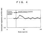
FIG. 4 is a diagram showing trends of NOx at the denitrization apparatus exit when switching from the constant-pressure operation to the variable pressure operation is performed before reaching a variable pressure operation temperature in the embodiment of the present invention. -
FIG. 5 is a diagram showing trends of NOx at the denitrization apparatus exit when switching from the constant-pressure operation to the variable pressure operation is performed after reaching the variable pressure operation temperature in the embodiment of the present invention. - An embodiment of the present invention shall now be described along with the drawings.
-
FIG. 1 is a configuration diagram of the exhaust gas purifying system of a boiler plant, andFIG. 2 is a configuration diagram of a hydrolytic separator using urea that injects ammonia gas from an ammoniagas injection nozzle 8 into an exit exhaust gas flue of aboiler 1 ofFIG. 1 . - In
FIG. 1 , ammonia gas is injected from the ammoniagas injection nozzle 8 into the exit exhaust gas flue of theboiler 1 to decompose NOx in the exhaust gas into water vapor and nitrogen gas at adenitrization apparatus 2 at a downstream side of the flue. Thereafter, the exhaust gas undergoes heat exchange with combustion air at anair preheater 3 and is removed of dust by anelectrostatic precipitator 4. The exhaust gas that is removed of dust is then raised in pressure by aninduction fan 5, sulfur oxide (SO2) in the exhaust gas is thereafter removed by adesulfurizer 6, and the exhaust gas is discharged into air from astack 7. -
FIG. 2 shows the configuration of the system by which the ammonia gas to be injected into the boiler exit flue is generated from urea. An aqueous urea solution 15 stored in the aqueous ureasolution storage tank 14 is fed into the hydrolytic separator 12 by a pump 13. In an interior of the hydrolytic separator 12, the aqueous urea solution is heated by a hydrolytic separator heating steam 11 supplied from theboiler 1 side, and a temperature inside the hydrolytic separator 12 is controlled by the hydrolytic separator heating steamflow control valve 10. Ammonia gas, which is generated at the hydrolytic separator 12 and contains carbon dioxide gas (CO2) and water vapor, is subject to flow rate control by an ammonia gasflow control valve 9 to a flow rate controlled according to NOx control logic in an exit exhaust gas of thedenitrization apparatus 2 shown inFIG. 1 and is injected into the exit flue of theboiler 1 from the ammoniagas injection nozzle 8. - The pressure and temperature of the hydrolytic separator 12 are controlled by a flow rate of the hydrolytic separator heating steam. The constant-pressure operation and variable pressure operation curves are shown in
FIG. 3 together with switching points and switching completion points thereof. In the present embodiment, in switching from the constant-pressure operation to the variable pressure operation during plant startup, switching was performed respectively before (constant-pressure/variablepressure switching point 1 ofFIG. 3 ) and after (constant-pressure/variablepressure switching point 2 ofFIG. 3 ) a variable pressure operation temperature was reached to compare how the switching influences the exit exhaust gas NOx concentration of thedenitrization apparatus 2. - Variations of the (exit exhaust gas NOx concentration during the variable pressure operation) / (ratio of exit exhaust gas NOx concentration during the constant-pressure operation) of the NOx concentration in the exit exhaust gas of the
denitrization apparatus 2 with respect to boiler load are shown for the two conditions inFIG. 4 andFIG. 5 , respectively. - In the case where switching from the constant-pressure operation to the variable pressure operation is performed at the constant-pressure/variable
pressure switching point 1, the pressure during the constant-pressure operation of the hydrolytic separator 12 is higher than the pressure during the variable pressure operation, and thus a control in a direction of lowering the pressure acts as shown inFIG. 3 so that the heating steam amount of the hydrolytic separator 12 decreases and the temperature decreases along with the decrease in pressure. The ammonia generation amount decreases in accordance with the decrease in temperature and thus the ammonia concentration in the gas generated from the hydrolytic separator 12 decreases and this consequently causes a rise of NOx concentration in the exit exhaust gas of thedenitrization apparatus 2. - On the other hand, in the case where switching from the constant-pressure operation to the variable pressure operation is performed at the constant-pressure/variable
pressure switching point 2, a control is performed oppositely so as to raise the pressure so that the amount of heating steam supplied to the hydrolytic separator 12 increases and the temperature rises. Consequently, the ammonia generation amount increases and this acts to lower the NOx concentration in the exit exhaust gas of thedenitrization apparatus 2 so that the plant can be operated with stability while suppressing increase in the exit NOx. - When in an apparatus for generating ammonia from an aqueous urea solution, control does not act in a satisfactory manner, control of exhaust gas NOx concentration at the denitrization apparatus exit for purifying the exhaust gas from a boiler, etc. , is disabled and a problem of increased NOx emission amount occurs. Also, temperature rise of the aqueous urea solution causes a boiling phenomenon and thermal decomposition of the aqueous urea solution to occur and thus causes problem in terms of equipment operation. The present invention is effective for minimizing the NOx emission amount from the exhaust gas while enabling stable operation of the urea equipment.
-
- 1
- Boiler
- 2
- Denitrization apparatus
- 3
- Air preheater
- 4
- Electrostatic precipitator
- 5
- Induction fan
- 6
- Desulfurizer
- 7
- Stack
- 8
- Ammonia gas injection nozzle
- 9
- Ammonia gas flow control valve
- 10
- Hydrolytic separator heating steam flow control valve
- 11
- Hydrolytic separator heating steam
- 12
- Hydrolytic separator
- 13
- Aqueous urea solution transport pump
- 14
- Aqueous urea solution storage tank
- 15
- Aqueous urea solution
Claims (2)
- A method of operating a hydrolytic separator during startup of the hydrolytic separator at which ammonia gas, to be used as a reducing agent in a flue gas denitrization apparatus, is generated by hydrolysis of an aqueous urea solution, wherein
a constant-pressure operation, in which an internal pressure of the hydrolytic separator is kept constant with respect to a temperature rise of the hydrolytic separator, is performed when ammonia gas injection is initiated, an operation of switching to a variable pressure operation, in which the pressure of the hydrolytic separator is raised as the temperature of the hydrolytic separator rises, is performed thereafter, and a switching point from the constant-pressure operation to the variable pressure operation is set at the hydrolytic separator temperature in constant-pressure operation that is no less than the variable pressure operation temperature corresponding to the pressure at that point. - The method of operating the hydrolytic separator according to Claim 1, wherein an upper limit of the switching point from the constant-pressure operation to the variable pressure operation is set to no more than a boiling point of the aqueous urea solution.
Applications Claiming Priority (2)
| Application Number | Priority Date | Filing Date | Title |
|---|---|---|---|
| JP2008141321A JP5269483B2 (en) | 2008-05-29 | 2008-05-29 | Operation method of water separator |
| PCT/JP2009/002340 WO2009144931A1 (en) | 2008-05-29 | 2009-05-27 | Method of operating hydrolytic separator |
Publications (2)
| Publication Number | Publication Date |
|---|---|
| EP2279784A1 true EP2279784A1 (en) | 2011-02-02 |
| EP2279784A4 EP2279784A4 (en) | 2014-07-16 |
Family
ID=41376821
Family Applications (1)
| Application Number | Title | Priority Date | Filing Date |
|---|---|---|---|
| EP09754440.7A Withdrawn EP2279784A4 (en) | 2008-05-29 | 2009-05-27 | Method of operating hydrolytic separator |
Country Status (4)
| Country | Link |
|---|---|
| US (1) | US20110033360A1 (en) |
| EP (1) | EP2279784A4 (en) |
| JP (1) | JP5269483B2 (en) |
| WO (1) | WO2009144931A1 (en) |
Cited By (1)
| Publication number | Priority date | Publication date | Assignee | Title |
|---|---|---|---|---|
| CN104076801A (en) * | 2014-07-10 | 2014-10-01 | 大唐阳城发电有限责任公司 | Automatic ultrahigh tension long-distance transmission line malfunction load shedding system and method |
Families Citing this family (3)
| Publication number | Priority date | Publication date | Assignee | Title |
|---|---|---|---|---|
| US9586831B2 (en) * | 2014-06-09 | 2017-03-07 | Wahlco, Inc. | Urea to ammonia process |
| CN107188198A (en) * | 2017-06-28 | 2017-09-22 | 西安热工研究院有限公司 | A kind of thermal power plant's denitration is pyrolyzed with hydrolysis of urea and is combined ammonia system processed |
| CN111167276B (en) * | 2020-01-19 | 2021-01-05 | 肇庆新川绿色科技有限公司 | Denitration method in alkali recovery furnace |
Family Cites Families (4)
| Publication number | Priority date | Publication date | Assignee | Title |
|---|---|---|---|---|
| US6436359B1 (en) * | 2000-10-25 | 2002-08-20 | Ec&C Technologies, Inc. | Method for controlling the production of ammonia from urea for NOx scrubbing |
| US6761868B2 (en) * | 2001-05-16 | 2004-07-13 | The Chemithon Corporation | Process for quantitatively converting urea to ammonia on demand |
| JP4646063B2 (en) * | 2005-02-15 | 2011-03-09 | バブコック日立株式会社 | Exhaust gas denitration method and apparatus using urea decomposition catalyst |
| US20090148370A1 (en) * | 2007-12-06 | 2009-06-11 | Spencer Iii Herbert W | Process to produce ammonia from urea |
-
2008
- 2008-05-29 JP JP2008141321A patent/JP5269483B2/en not_active Expired - Fee Related
-
2009
- 2009-05-27 EP EP09754440.7A patent/EP2279784A4/en not_active Withdrawn
- 2009-05-27 WO PCT/JP2009/002340 patent/WO2009144931A1/en not_active Ceased
- 2009-05-27 US US12/936,299 patent/US20110033360A1/en not_active Abandoned
Cited By (2)
| Publication number | Priority date | Publication date | Assignee | Title |
|---|---|---|---|---|
| CN104076801A (en) * | 2014-07-10 | 2014-10-01 | 大唐阳城发电有限责任公司 | Automatic ultrahigh tension long-distance transmission line malfunction load shedding system and method |
| CN104076801B (en) * | 2014-07-10 | 2017-02-15 | 大唐阳城发电有限责任公司 | Automatic ultrahigh tension long-distance transmission line malfunction load shedding system and method |
Also Published As
| Publication number | Publication date |
|---|---|
| EP2279784A4 (en) | 2014-07-16 |
| US20110033360A1 (en) | 2011-02-10 |
| JP2009285578A (en) | 2009-12-10 |
| JP5269483B2 (en) | 2013-08-21 |
| WO2009144931A1 (en) | 2009-12-03 |
Similar Documents
| Publication | Publication Date | Title |
|---|---|---|
| KR102172147B1 (en) | Low Pressure Selective Catalytic Reduction System and Urea Storage Tank Heating Control Method Thereof | |
| KR101367024B1 (en) | Urea hydrolysis apparatus using fuel cell and selective catalytic reuction system with the same | |
| KR100492112B1 (en) | METHOD FOR CONTROLLING THE PRODUCTION OF AMMONIA FROM UREA FOR NOx SCRUBBING | |
| KR101519173B1 (en) | Urea atomization system with catalytic converter for SCR system | |
| KR101277518B1 (en) | Scr/sncr combined de-nox system for reducing yellow plume and nox | |
| KR101807996B1 (en) | Combined De-NOx System using Heterogeneous Reducing agent for Reducing Yellow Plume and NOx | |
| JP3727668B2 (en) | Exhaust gas boiler | |
| KR101002888B1 (en) | Hybrid system to remove nitrogen oxides in boiler exhaust | |
| JP4959303B2 (en) | Exhaust gas treatment method and treatment apparatus | |
| CA2685555C (en) | A method for the conversion of urea to reactants for nox reduction | |
| US20110033360A1 (en) | Method of operating hydrolytic separator | |
| JP3638638B2 (en) | Denitration equipment using solid reducing agent | |
| US20120102913A1 (en) | Apparatus for reducing emissions and method of assembly | |
| JPH0871372A (en) | Denitration device and method using urea | |
| EP1353042A2 (en) | A gas turbine single plant modifying method, a catalyst re-using method and a re-produced catalyst | |
| WO2004099076A2 (en) | Methods and apparatus for small-scale synthesis of ammonia | |
| KR100437875B1 (en) | NOx reduction system by selective catalytic reduction available for urea as reducing agent | |
| KR101433611B1 (en) | SCR De-Nox Equipment for removing yellow plume | |
| KR101735535B1 (en) | Apparatus for Removing Nitrogen Oxides | |
| JP2013136995A (en) | System for supplying ammonia to scr converter | |
| CN106237845A (en) | The method of the desulphurization denitration of flue gases of cock oven | |
| CN117967461A (en) | Green and low-carbon monitoring system | |
| KR100876161B1 (en) | NOx Reduction System | |
| JP2005324106A (en) | Flue gas denitration apparatus and its activation method | |
| KR20210115916A (en) | NOx REMOVING SYSTEM THROUGH OXIDATION, DEOXIDATION AND RETURN OF EXHAUST GAS |
Legal Events
| Date | Code | Title | Description |
|---|---|---|---|
| PUAI | Public reference made under article 153(3) epc to a published international application that has entered the european phase |
Free format text: ORIGINAL CODE: 0009012 |
|
| 17P | Request for examination filed |
Effective date: 20101013 |
|
| AK | Designated contracting states |
Kind code of ref document: A1 Designated state(s): AT BE BG CH CY CZ DE DK EE ES FI FR GB GR HR HU IE IS IT LI LT LU LV MC MK MT NL NO PL PT RO SE SI SK TR |
|
| AX | Request for extension of the european patent |
Extension state: AL BA RS |
|
| DAX | Request for extension of the european patent (deleted) | ||
| A4 | Supplementary search report drawn up and despatched |
Effective date: 20140616 |
|
| RIC1 | Information provided on ipc code assigned before grant |
Ipc: F01N 3/20 20060101ALI20140610BHEP Ipc: C01C 1/08 20060101AFI20140610BHEP Ipc: B01D 53/74 20060101ALI20140610BHEP Ipc: B01D 53/94 20060101ALI20140610BHEP Ipc: B01D 53/56 20060101ALI20140610BHEP |
|
| RAP1 | Party data changed (applicant data changed or rights of an application transferred) |
Owner name: MITSUBISHI HITACHI POWER SYSTEMS, LTD. |
|
| RAP1 | Party data changed (applicant data changed or rights of an application transferred) |
Owner name: MITSUBISHI HITACHI POWER SYSTEMS, LTD. |
|
| 17Q | First examination report despatched |
Effective date: 20150527 |
|
| STAA | Information on the status of an ep patent application or granted ep patent |
Free format text: STATUS: THE APPLICATION IS DEEMED TO BE WITHDRAWN |
|
| 18D | Application deemed to be withdrawn |
Effective date: 20151007 |