EP2278298A1 - Quartz oscillator and measurement method using same - Google Patents
Quartz oscillator and measurement method using same Download PDFInfo
- Publication number
- EP2278298A1 EP2278298A1 EP09746624A EP09746624A EP2278298A1 EP 2278298 A1 EP2278298 A1 EP 2278298A1 EP 09746624 A EP09746624 A EP 09746624A EP 09746624 A EP09746624 A EP 09746624A EP 2278298 A1 EP2278298 A1 EP 2278298A1
- Authority
- EP
- European Patent Office
- Prior art keywords
- crystal oscillator
- frequency
- frequencies
- measured
- density
- Prior art date
- Legal status (The legal status is an assumption and is not a legal conclusion. Google has not performed a legal analysis and makes no representation as to the accuracy of the status listed.)
- Withdrawn
Links
- 238000000691 measurement method Methods 0.000 title claims abstract description 8
- 239000010453 quartz Substances 0.000 title 1
- VYPSYNLAJGMNEJ-UHFFFAOYSA-N silicon dioxide Inorganic materials O=[Si]=O VYPSYNLAJGMNEJ-UHFFFAOYSA-N 0.000 title 1
- 239000013078 crystal Substances 0.000 claims abstract description 77
- 239000000463 material Substances 0.000 claims abstract description 27
- 238000005259 measurement Methods 0.000 claims description 23
- 238000000034 method Methods 0.000 claims description 17
- 238000010586 diagram Methods 0.000 claims description 13
- 239000000243 solution Substances 0.000 description 52
- PEDCQBHIVMGVHV-UHFFFAOYSA-N Glycerine Chemical compound OCC(O)CO PEDCQBHIVMGVHV-UHFFFAOYSA-N 0.000 description 15
- 238000003380 quartz crystal microbalance Methods 0.000 description 9
- PCHJSUWPFVWCPO-UHFFFAOYSA-N gold Chemical compound [Au] PCHJSUWPFVWCPO-UHFFFAOYSA-N 0.000 description 4
- 239000010931 gold Substances 0.000 description 4
- 229910052737 gold Inorganic materials 0.000 description 4
- 239000007788 liquid Substances 0.000 description 4
- 230000010355 oscillation Effects 0.000 description 4
- 239000008367 deionised water Substances 0.000 description 3
- 229910021641 deionized water Inorganic materials 0.000 description 3
- 239000007792 gaseous phase Substances 0.000 description 3
- XLYOFNOQVPJJNP-UHFFFAOYSA-N water Chemical compound O XLYOFNOQVPJJNP-UHFFFAOYSA-N 0.000 description 3
- 239000007864 aqueous solution Substances 0.000 description 2
- 238000010408 sweeping Methods 0.000 description 2
- XAGFODPZIPBFFR-UHFFFAOYSA-N aluminium Chemical compound [Al] XAGFODPZIPBFFR-UHFFFAOYSA-N 0.000 description 1
- 229910052782 aluminium Inorganic materials 0.000 description 1
- 239000012620 biological material Substances 0.000 description 1
- 238000006243 chemical reaction Methods 0.000 description 1
- 238000001739 density measurement Methods 0.000 description 1
- 238000000151 deposition Methods 0.000 description 1
- 238000001514 detection method Methods 0.000 description 1
- 239000007789 gas Substances 0.000 description 1
- 230000003993 interaction Effects 0.000 description 1
- 239000007791 liquid phase Substances 0.000 description 1
- 238000004519 manufacturing process Methods 0.000 description 1
- 238000005498 polishing Methods 0.000 description 1
- 238000002360 preparation method Methods 0.000 description 1
- 102000004169 proteins and genes Human genes 0.000 description 1
- 108090000623 proteins and genes Proteins 0.000 description 1
- 238000002494 quartz crystal microgravimetry Methods 0.000 description 1
- 230000035945 sensitivity Effects 0.000 description 1
- 238000004544 sputter deposition Methods 0.000 description 1
- 239000012086 standard solution Substances 0.000 description 1
- 238000003756 stirring Methods 0.000 description 1
- 239000000126 substance Substances 0.000 description 1
- 238000007740 vapor deposition Methods 0.000 description 1
Images

Classifications
-
- G—PHYSICS
- G01—MEASURING; TESTING
- G01N—INVESTIGATING OR ANALYSING MATERIALS BY DETERMINING THEIR CHEMICAL OR PHYSICAL PROPERTIES
- G01N11/00—Investigating flow properties of materials, e.g. viscosity, plasticity; Analysing materials by determining flow properties
- G01N11/10—Investigating flow properties of materials, e.g. viscosity, plasticity; Analysing materials by determining flow properties by moving a body within the material
- G01N11/16—Investigating flow properties of materials, e.g. viscosity, plasticity; Analysing materials by determining flow properties by moving a body within the material by measuring damping effect upon oscillatory body
-
- G—PHYSICS
- G01—MEASURING; TESTING
- G01N—INVESTIGATING OR ANALYSING MATERIALS BY DETERMINING THEIR CHEMICAL OR PHYSICAL PROPERTIES
- G01N29/00—Investigating or analysing materials by the use of ultrasonic, sonic or infrasonic waves; Visualisation of the interior of objects by transmitting ultrasonic or sonic waves through the object
- G01N29/02—Analysing fluids
- G01N29/022—Fluid sensors based on microsensors, e.g. quartz crystal-microbalance [QCM], surface acoustic wave [SAW] devices, tuning forks, cantilevers, flexural plate wave [FPW] devices
-
- G—PHYSICS
- G01—MEASURING; TESTING
- G01N—INVESTIGATING OR ANALYSING MATERIALS BY DETERMINING THEIR CHEMICAL OR PHYSICAL PROPERTIES
- G01N29/00—Investigating or analysing materials by the use of ultrasonic, sonic or infrasonic waves; Visualisation of the interior of objects by transmitting ultrasonic or sonic waves through the object
- G01N29/02—Analysing fluids
- G01N29/036—Analysing fluids by measuring frequency or resonance of acoustic waves
-
- G—PHYSICS
- G01—MEASURING; TESTING
- G01N—INVESTIGATING OR ANALYSING MATERIALS BY DETERMINING THEIR CHEMICAL OR PHYSICAL PROPERTIES
- G01N29/00—Investigating or analysing materials by the use of ultrasonic, sonic or infrasonic waves; Visualisation of the interior of objects by transmitting ultrasonic or sonic waves through the object
- G01N29/22—Details, e.g. general constructional or apparatus details
- G01N29/24—Probes
- G01N29/2437—Piezoelectric probes
-
- G—PHYSICS
- G01—MEASURING; TESTING
- G01N—INVESTIGATING OR ANALYSING MATERIALS BY DETERMINING THEIR CHEMICAL OR PHYSICAL PROPERTIES
- G01N9/00—Investigating density or specific gravity of materials; Analysing materials by determining density or specific gravity
-
- G—PHYSICS
- G01—MEASURING; TESTING
- G01N—INVESTIGATING OR ANALYSING MATERIALS BY DETERMINING THEIR CHEMICAL OR PHYSICAL PROPERTIES
- G01N9/00—Investigating density or specific gravity of materials; Analysing materials by determining density or specific gravity
- G01N9/002—Investigating density or specific gravity of materials; Analysing materials by determining density or specific gravity using variation of the resonant frequency of an element vibrating in contact with the material submitted to analysis
-
- G—PHYSICS
- G01—MEASURING; TESTING
- G01R—MEASURING ELECTRIC VARIABLES; MEASURING MAGNETIC VARIABLES
- G01R1/00—Details of instruments or arrangements of the types included in groups G01R5/00 - G01R13/00 and G01R31/00
-
- G—PHYSICS
- G01—MEASURING; TESTING
- G01N—INVESTIGATING OR ANALYSING MATERIALS BY DETERMINING THEIR CHEMICAL OR PHYSICAL PROPERTIES
- G01N2291/00—Indexing codes associated with group G01N29/00
- G01N2291/02—Indexing codes associated with the analysed material
- G01N2291/028—Material parameters
- G01N2291/02818—Density, viscosity
-
- G—PHYSICS
- G01—MEASURING; TESTING
- G01N—INVESTIGATING OR ANALYSING MATERIALS BY DETERMINING THEIR CHEMICAL OR PHYSICAL PROPERTIES
- G01N2291/00—Indexing codes associated with group G01N29/00
- G01N2291/04—Wave modes and trajectories
- G01N2291/042—Wave modes
- G01N2291/0426—Bulk waves, e.g. quartz crystal microbalance, torsional waves
Definitions
- the present invention relates to a crystal oscillator, and a measurement method using same with which the density of a solution can be measured alone, or both the density and the viscosity of a solution can be measured at the same time.
- the QCM (Quartz Crystal Microbalance) method that utilizes the resonance phenomenon of a crystal oscillator allows for the detection of even very small mass changes using a simple apparatus, not only for measurements in a gaseous phase but also in a liquid phase. For this reason, the QCM method has been widely used for, for example, gas sensors, film thickness sensors, chemical sensors, and biosensors that measure interactions of biological materials such as DNA and protein. Conventionally, the QCM method is applied in a variety of measurements by being used to measure the resonant frequency that results from oscillation, or the resonant frequency obtained by sweeping a frequency using a device such as an impedance analyzer and a network analyzer.
- Patent Documents 1 and 2 propose methods for measuring solution density and viscosity using a sensor provided with two or more detectors. At least one of the detectors is used as a reference detector that measures the frequency due to solution resistance, and the solution resistance component of the reference detectors is removed from the measurement results of the other detectors so as to measure the density and viscosity of the solution.
- it is laborious to provide a plurality of detectors for a single piezoelectric plate, or to use a plurality of sensors. In addition to being laborious, it increases the manufacturing cost of the sensor.
- Another problem is the individual differences among the detectors. Further, drawing a standard curve with a single sensor requires preparation of a plurality of standard samples, and it takes time to start the actual measurement. Further, because the density and viscosity can only be determined from the resonant frequency that contains the information of both density and viscosity, measurement accuracy is considerably low.
- a measurement method of a first solution means of the present invention includes: contacting a material to be measured to the crystal oscillator and oscillating the crystal oscillator that includes electrodes formed on both surfaces of a piezoelectric plate, and an uneven-surface formed either on one of the electrodes disposed on the side in contact with the material to be measured, or on a detector formed on the electrode; and measuring an amount of change in frequency (f 2 ) that corresponds to the high-frequency side of two frequencies that represent a half value of a conductance maximum value of the crystal oscillator, so as to measure a density of the material.
- a second solution means In a second solution means according to the first solution means, amounts of change of at least two of the frequencies on an admittance circle diagram of the crystal oscillator are measured to also measure a viscosity of the material.
- the at least two frequencies on the admittance circle diagram are any two of frequencies (f 1 , f 2 ) that represent the half value of the conductance maximum value of the crystal oscillator, and a resonant frequency (f s ) of the crystal oscillator.
- the frequency (f 2 ) is obtained by directly measuring a frequency that corresponds to a susceptance minimum value (B min ) on an admittance circle diagram of the crystal oscillator.
- the viscosity of the material is also measured by measuring amounts of change of at least two of the frequencies between two frequencies (f 1 , f 2 ) that represent a half value of a conductance maximum value of the crystal oscillator.
- the at least two frequencies are any two of the frequencies (f 1 , f 2 ) that represent the half value of the conductance maximum value of the crystal oscillator, and a resonant frequency (f s ) of the crystal oscillator.
- the frequency (f 2 ) is obtained through indirect measurement from (I) a frequency (f 1 ) that corresponds to the low-frequency side of two frequencies that represent a half value of a conductance maximum value of the crystal oscillator, and (II) a resonant frequency (f s ).
- the measurement is made using a fundamental frequency or a higher-order wave of the crystal oscillator.
- a crystal oscillator of a ninth solution means of the present invention includes electrodes on both surfaces of a piezoelectric plate, and a density-measuring uneven-surface formed either on one of the electrodes disposed on the side in contact with a material to be measured, or on a detector formed on the electrode.
- the uneven-surface is a surface with an arithmetic average roughness (Ra) of from 0.1 ⁇ m to 20 ⁇ m.
- the uneven-surface includes a plurality of grooves formed adjacent to one another.
- the present invention overcomes the limitations of the conventional QCM method, and enables the measurement of solution density alone, or the simultaneous measurement of density and viscosity with ease using only a crystal oscillator that includes a single detector.
- the crystal oscillator used in the present invention includes electrodes on the both surfaces of a piezoelectric plate, and an uneven-surface formed on the electrode disposed on the side in contact with a material to be measured, or on a detector formed on the electrode by vapor deposition or sputtering.
- the uneven-surface can be formed on the electrode surface or the detector surface, for example, by making the surface of the crystal plate uneven such as patterned indented or roughed beforehand in a portion to be provided with the detector, or by depositing an electrode-forming metallic film on a surface of the crystal plate after subjected to limited polishing.
- the uneven-surface may be provided only in portions of the electrode surface or the detector.
- the uneven-surface is a surface with an arithmetic average roughness (Ra) of from 0.1 ⁇ m to 20 ⁇ m.
- Ra arithmetic average roughness
- the uneven-surface has a groove, preferably a plurality of grooves. In this way, the uneven-surface can provide recesses for accepting the material to be measured.
- the groove has a width of about 0.1 to 100 ⁇ m, and a depth of about 0.1 to 40 ⁇ m.
- the grooves are provided to extend in a direction crossing the oscillation direction of the crystal plate, preferably a direction perpendicular to the oscillation direction, in order to ensure trapping of the material to be measured in the grooves.
- the crystal oscillator is oscillated at a predetermined frequency, and a material to be measured is contacted to the electrode or the detector formed on the electrode. Measurement is made with regard to an amount of change in frequency (f 2 ) that corresponds to the high-frequency side of the two frequencies that represent the half value of the conductance maximum value of the crystal oscillator. Amounts of change of at least two frequencies on an admittance circle diagram ( Fig. 1 ) that represents the characteristic of the crystal oscillator are also measured.
- the amounts of frequency change on the admittance circle diagram are the same for the mass loading of the material, but the amounts of frequency change due to solution resistance become different for different frequencies.
- the amount of frequency change due to solution resistance for frequency f 1 that corresponds to the low-frequency side of the frequencies that represent the half value of the conductance maximum value of the crystal oscillator becomes twice as large as the amount of frequency change due to solution resistance for resonant frequency f s .
- the amount of frequency change due to solution resistance is almost zero for the frequency f 2 that corresponds to the high-frequency side of the frequencies that represent the half value of the conductance maximum value of the crystal oscillator.
- f 0 is the fundamental frequency
- ⁇ L the viscosity
- ⁇ 0 the density of the crystal oscillator
- ⁇ 0 the modulus of transverse elasticity of the crystal oscillator
- ⁇ m the amount of mass change
- A the electrode area
- ⁇ L the density of the solution
- ⁇ L the solution viscosity
- the amount of frequency change in f 2 gives the mass of the material to be measured captured on the concave part of uneven-surface by the oscillating electrode of the crystal oscillator, upon measuring f 1 , f 2 , and f s .
- the mass so obtained from equation (3) can then be used to determine density, by dividing the mass by the previously measured or derived volume of the liquid captured on the concave part of uneven-surface.
- the amount of change in f s is due to both solution resistance and mass loading.
- the amount of change in f 1 is also due to both solution resistance and mass loading.
- the frequencies measured to obtain the amount of frequency change due to only the resistance component of the material to be measured on the oscillating surface of the crystal oscillator are not particularly limited, as long as they are at least two frequencies on the admittance circle diagram.
- the frequencies are not limited to f 1 and f 2 , and may be f 1 and f s , or f s and f 2 .
- the frequencies used for the measurement are not limited to fundamental waves, and higher-order waves of these frequencies also can be used. In this way, the pressure wave that occurs between the crystal oscillator and the liquid surface can be reduced, and a solution measurement is enabled in even smaller quantities, as described in JP-A-2005-98866 .
- the frequency measurements may be performed using a frequency counter by measuring the oscillation of the crystal oscillator, or by sweeping the frequencies using an impedance analyzer or a network analyzer.
- the sensor portion including the sensor may be of, for example, a cup type, a liquid droplet placement type, or a flow-cell type. Measurement of solution density and viscosity is possible regardless of the shape of the sensor portion.
- a 27-MHz crystal oscillator 3 including gold electrodes 2, 2 on the both sides of a piezoelectric plate 1 was prepared.
- a plurality of grooves 4 having a rectangular cross section is provided adjacent to one another on the surface of the gold electrode 2 in contact with a solution, so as to form a detector on the electrode 2.
- the electrodes 2.2 were formed using gold that had a diameter of 2.7 mm.
- the width W and the interval I of the grooves 4 were both 5 ⁇ m.
- the depth D of the grooves was 600 nm.
- the crystal oscillator 3 was placed in an aluminum block provided with an automatic stirring function and a temperature regulator.
- the crystal oscillator 3 as a sensor 5 was then connected, as illustrated in Fig. 4 , to a frequency-measuring network analyzer 7 via a ⁇ circuit 6, and the network analyzer 7 was adapted to send signals to a personal computer 8.
- the sensor 5 was used to maintain the material to be measured to a liquid temperature of 25°C during the measurement, which was performed as follows.
- Frequencies were measured for a standard sample (deionized water; 500 ⁇ l), and for glycerol aqueous solutions of known density and known viscosity (10 wt%, 30 wt%, and 50 wt% samples; 500 ⁇ l each) placed on the electrode 4 of the crystal oscillator 3.
- Table 1 below presents amounts of change in frequency f 2 , resonant frequency f s , and the frequency (f 1 -f 2 )/2 determined from f 1 and f 2
- the resonant frequency f s was measured for comparison with the resonant frequency obtained by the conventional QCM method.
- the detected value of resonant frequency f s in the conventional QCM method is the sum of the frequency detected as the mass of the sample captured by the concave of the detector, plus the frequency due to solution resistance. Thus, the measured amount of frequency change cannot be used to determine the amount of the solution of the detected mass captured by the concave.
- the amount of the solution of the detected mass captured by the concave on the electrode 2 was 213 pl. Using this value, the densities of the 10 wt%, 30 wt%, and 50 wt% glycerol aqueous solutions were calculated from the amounts of frequency change of these samples. The results are presented in Table 2 below, and in the graph of Fig. 5 .
- Viscosities were determined from the amounts of frequency change in (f 1 - f 2 )/2 representing the frequency of only the solution resistance component on the oscillating surface of the crystal oscillator 3, using the densities obtained from the amounts of frequency change as above. Note that the calculations were made at the density 2.65 g/cm 3 of the crystal oscillator 3, and at the modulus of transverse elasticity 2.95 ⁇ 10 11 g/cm ⁇ S 2 of the crystal oscillator 3. Viscosities ⁇ were calculated by substituting the numerical values in equation (4). The results are presented in Table 3 below, and in the graph of Fig. 6 .
- the viscosity values determined from the amounts of frequency change were close to the viscosities calculated using the values of Kagaku Binran as reference.
- the present invention can be used for the measurement of density and/or viscosity using a minute amount of solution.
Landscapes
- Physics & Mathematics (AREA)
- General Physics & Mathematics (AREA)
- General Health & Medical Sciences (AREA)
- Chemical & Material Sciences (AREA)
- Analytical Chemistry (AREA)
- Biochemistry (AREA)
- Life Sciences & Earth Sciences (AREA)
- Health & Medical Sciences (AREA)
- Immunology (AREA)
- Pathology (AREA)
- Acoustics & Sound (AREA)
- Investigating Or Analyzing Materials By The Use Of Ultrasonic Waves (AREA)
- Piezo-Electric Or Mechanical Vibrators, Or Delay Or Filter Circuits (AREA)
- Investigating Or Analyzing Materials By The Use Of Electric Means (AREA)
Abstract
Description
- The present invention relates to a crystal oscillator, and a measurement method using same with which the density of a solution can be measured alone, or both the density and the viscosity of a solution can be measured at the same time.
- The QCM (Quartz Crystal Microbalance) method that utilizes the resonance phenomenon of a crystal oscillator allows for the detection of even very small mass changes using a simple apparatus, not only for measurements in a gaseous phase but also in a liquid phase. For this reason, the QCM method has been widely used for, for example, gas sensors, film thickness sensors, chemical sensors, and biosensors that measure interactions of biological materials such as DNA and protein.
Conventionally, the QCM method is applied in a variety of measurements by being used to measure the resonant frequency that results from oscillation, or the resonant frequency obtained by sweeping a frequency using a device such as an impedance analyzer and a network analyzer.
In QCM measurement performed in a gaseous phase, only the mass of the material adhered to an electrode surface is detected as an amount of frequency change, and accordingly conversion into density is relatively easy.
However, in the measurement of solution density and viscosity, it has been difficult to separately measure the density and the viscosity of the solution using the conventional QCM method, because, unlike measurement in a gaseous phase, the frequency change due to the solution resistance on the oscillating surface of a crystal oscillator has a correlation with the product of density and viscosity.
Thus, if the density and viscosity were both unknown, the values of density and viscosity cannot be determined using the conventional QCM method.
As a countermeasure,Patent Documents
However, it is laborious to provide a plurality of detectors for a single piezoelectric plate, or to use a plurality of sensors. In addition to being laborious, it increases the manufacturing cost of the sensor. Another problem is the individual differences among the detectors.
Further, drawing a standard curve with a single sensor requires preparation of a plurality of standard samples, and it takes time to start the actual measurement. Further, because the density and viscosity can only be determined from the resonant frequency that contains the information of both density and viscosity, measurement accuracy is considerably low. -
- Patent Document 1:
US Patent No. 5,741,961 - Patent Document 2:
US Patent No. 5,798,452 - It is an object of the present invention to provide a crystal oscillator, and a measurement method using same with which the density of a solution can be measured alone, or both the density and the viscosity of a solution can be measured at the same time using a single detector provided for the crystal oscillator.
- In order to solve the foregoing problems, a measurement method of a first solution means of the present invention includes: contacting a material to be measured to the crystal oscillator and oscillating the crystal oscillator that includes electrodes formed on both surfaces of a piezoelectric plate, and an uneven-surface formed either on one of the electrodes disposed on the side in contact with the material to be measured, or on a detector formed on the electrode; and measuring an amount of change in frequency (f2) that corresponds to the high-frequency side of two frequencies that represent a half value of a conductance maximum value of the crystal oscillator, so as to measure a density of the material.
In a second solution means according to the first solution means, amounts of change of at least two of the frequencies on an admittance circle diagram of the crystal oscillator are measured to also measure a viscosity of the material.
In a third solution means according to the second solution means, the at least two frequencies on the admittance circle diagram are any two of frequencies (f1, f2) that represent the half value of the conductance maximum value of the crystal oscillator, and a resonant frequency (fs) of the crystal oscillator.
In a fourth solution means according to the first solution means, the frequency (f2) is obtained by directly measuring a frequency that corresponds to a susceptance minimum value (Bmin) on an admittance circle diagram of the crystal oscillator.
In a fifth solution means according to the first solution means, the viscosity of the material is also measured by measuring amounts of change of at least two of the frequencies between two frequencies (f1, f2) that represent a half value of a conductance maximum value of the crystal oscillator.
In a sixth solution means according to the fifth solution means, the at least two frequencies are any two of the frequencies (f1, f2) that represent the half value of the conductance maximum value of the crystal oscillator, and a resonant frequency (fs) of the crystal oscillator.
In a seventh solution means according to the first solution means, the frequency (f2) is obtained through indirect measurement from (I) a frequency (f1) that corresponds to the low-frequency side of two frequencies that represent a half value of a conductance maximum value of the crystal oscillator, and (II) a resonant frequency (fs).
In an eighth solution means according to the first solution means, the measurement is made using a fundamental frequency or a higher-order wave of the crystal oscillator.
A crystal oscillator of a ninth solution means of the present invention includes electrodes on both surfaces of a piezoelectric plate, and a density-measuring uneven-surface formed either on one of the electrodes disposed on the side in contact with a material to be measured, or on a detector formed on the electrode.
In a tenth solution means according to the ninth solution means, the uneven-surface is a surface with an arithmetic average roughness (Ra) of from 0.1 µm to 20 µm.
In an eleventh solution means according to the ninth solution means, the uneven-surface includes a plurality of grooves formed adjacent to one another. - The present invention overcomes the limitations of the conventional QCM method, and enables the measurement of solution density alone, or the simultaneous measurement of density and viscosity with ease using only a crystal oscillator that includes a single detector.
-
-
Fig. 1 is an explanatory view showing an admittance circle diagram of a crystal oscillator. -
Fig. 2 shows (a) a plan view, (b) an A-A' cross sectional view, and (c) a B-B' cross sectional view of a crystal oscillator used in an example of the present invention. -
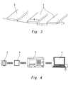
Fig. 3 is a perspective view explaining grooves provided for a detector of the crystal oscillator. -
Fig. 4 is an explanatory diagram illustrating an apparatus configuration used in the measurement method of the example of the present invention. -
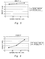
Fig. 5 is a graph comparing the density measurement result of the example and the densities presented in Kagaku Binran. -
Fig. 6 is a graph comparing the viscosity measurement result of the example and the viscosities presented in Kagaku Binran. - The crystal oscillator used in the present invention includes electrodes on the both surfaces of a piezoelectric plate, and an uneven-surface formed on the electrode disposed on the side in contact with a material to be measured, or on a detector formed on the electrode by vapor deposition or sputtering.
The uneven-surface can be formed on the electrode surface or the detector surface, for example, by making the surface of the crystal plate uneven such as patterned indented or roughed beforehand in a portion to be provided with the detector, or by depositing an electrode-forming metallic film on a surface of the crystal plate after subjected to limited polishing. The uneven-surface may be provided only in portions of the electrode surface or the detector.
Preferably, the uneven-surface is a surface with an arithmetic average roughness (Ra) of from 0.1 µm to 20 µm. With an Ra less than 0.1 µm, the density of the measured material cannot be measured, and accordingly viscosity cannot be determined. Above 20 µm, the crystal oscillator cannot maintain the state suited for measurement, possibly making the measured frequencies unstable, or failing to obtain frequencies.
Preferably, the uneven-surface has a groove, preferably a plurality of grooves. In this way, the uneven-surface can provide recesses for accepting the material to be measured. Preferably, the groove has a width of about 0.1 to 100 µm, and a depth of about 0.1 to 40 µm. Because the crystal plate oscillates in a certain direction parallel to the plate surface, the grooves are provided to extend in a direction crossing the oscillation direction of the crystal plate, preferably a direction perpendicular to the oscillation direction, in order to ensure trapping of the material to be measured in the grooves. - An embodiment of a measurement method of the present invention is described below, using the crystal oscillator described above.
First, the crystal oscillator is oscillated at a predetermined frequency, and a material to be measured is contacted to the electrode or the detector formed on the electrode.
Measurement is made with regard to an amount of change in frequency (f2) that corresponds to the high-frequency side of the two frequencies that represent the half value of the conductance maximum value of the crystal oscillator. Amounts of change of at least two frequencies on an admittance circle diagram (Fig. 1 ) that represents the characteristic of the crystal oscillator are also measured. - The amounts of frequency change on the admittance circle diagram are the same for the mass loading of the material, but the amounts of frequency change due to solution resistance become different for different frequencies.
Thus, for example, the amount of frequency change due to solution resistance for frequency f1 that corresponds to the low-frequency side of the frequencies that represent the half value of the conductance maximum value of the crystal oscillator becomes twice as large as the amount of frequency change due to solution resistance for resonant frequency fs. The amount of frequency change due to solution resistance is almost zero for the frequency f2 that corresponds to the high-frequency side of the frequencies that represent the half value of the conductance maximum value of the crystal oscillator.
This can be understood from the following approximation formulae for the frequencies f1, fs, and f2 in a solution.


- In the formulae (1) to (3), f0 is the fundamental frequency, N the order of the higher-order wave (N = 1, 3, 5, ...), ηL the viscosity, ρ0 the density of the crystal oscillator, µ0 the modulus of transverse elasticity of the crystal oscillator, Δm the amount of mass change, A the electrode area, ρL the density of the solution, and µL the solution viscosity.
- By taking advantage of the natures of these frequencies, for example, the amount of frequency change in f2, which does not depend on solution resistance, gives the mass of the material to be measured captured on the concave part of uneven-surface by the oscillating electrode of the crystal oscillator, upon measuring f1, f2, and fs.
The mass so obtained from equation (3) can then be used to determine density, by dividing the mass by the previously measured or derived volume of the liquid captured on the concave part of uneven-surface. - Because the amounts of frequency change due to mass loading are the same on the admittance circle diagram of the crystal oscillator, the amount of change in fs is due to both solution resistance and mass loading. Similarly, the amount of change in f1 is also due to both solution resistance and mass loading.
- Thus, viscosity ηL can be determined by substituting the density obtained from the amount of frequency change in f2, and the amount of frequency change due to only the resistance component of the measured material into the following equation (4).

where ΔfL is the amount of frequency change due to only the resistance component of the measured material on the oscillating surface of the crystal oscillator. - The frequency (f2) can be obtained either directly by measuring the frequency that corresponds to the minimum value (Bmin) of the susceptance in the admittance circle diagram, or indirectly from (I) the frequency (f1) that corresponds to the low-frequency side of the two frequencies that represent the half value of the conductance maximum value of the crystal oscillator, and (II) the resonant frequency (fs), using the relationship (f1 + f2)/2 = fs.
- The frequencies measured to obtain the amount of frequency change due to only the resistance component of the material to be measured on the oscillating surface of the crystal oscillator are not particularly limited, as long as they are at least two frequencies on the admittance circle diagram. The frequencies are not limited to f1 and f2, and may be f1 and fs, or fs and f2.
- The frequencies used for the measurement are not limited to fundamental waves, and higher-order waves of these frequencies also can be used. In this way, the pressure wave that occurs between the crystal oscillator and the liquid surface can be reduced, and a solution measurement is enabled in even smaller quantities, as described in
JP-A-2005-98866
The frequency measurements may be performed using a frequency counter by measuring the oscillation of the crystal oscillator, or by sweeping the frequencies using an impedance analyzer or a network analyzer.
The sensor portion including the sensor may be of, for example, a cup type, a liquid droplet placement type, or a flow-cell type. Measurement of solution density and viscosity is possible regardless of the shape of the sensor portion. - An example of the present invention is described below with reference to the accompanying drawings.
As illustrated inFig. 2 , a 27-MHz crystal oscillator 3 includinggold electrodes piezoelectric plate 1 was prepared. In thecrystal oscillator 3, as illustrated inFig. 3 , a plurality ofgrooves 4 having a rectangular cross section is provided adjacent to one another on the surface of thegold electrode 2 in contact with a solution, so as to form a detector on theelectrode 2.
The electrodes 2.2 were formed using gold that had a diameter of 2.7 mm. The width W and the interval I of thegrooves 4 were both 5 µm. The depth D of the grooves was 600 nm.
Thecrystal oscillator 3 was placed in an aluminum block provided with an automatic stirring function and a temperature regulator. Thecrystal oscillator 3 as asensor 5 was then connected, as illustrated inFig. 4 , to a frequency-measuringnetwork analyzer 7 via aπ circuit 6, and thenetwork analyzer 7 was adapted to send signals to apersonal computer 8.
Thesensor 5 was used to maintain the material to be measured to a liquid temperature of 25°C during the measurement, which was performed as follows. - Frequencies were measured for a standard sample (deionized water; 500 µl), and for glycerol aqueous solutions of known density and known viscosity (10 wt%, 30 wt%, and 50 wt% samples; 500 µl each) placed on the
electrode 4 of thecrystal oscillator 3. - Table 1 below presents amounts of change in frequency f2, resonant frequency fs, and the frequency (f1-f2)/2 determined from f1 and f2 The resonant frequency fs was measured for comparison with the resonant frequency obtained by the conventional QCM method.
-
[Table 1] Glycerol (wt%) Δf2 Δfs Δ(f1-f2)/2 0
(standard solution)-7070 -15855 -8795 10 -7347 -17418 -10079 30 -7620 -21412 -13792 50 -7953 -28697 -20780 - The amount of frequency change in f2 was Δf2 = -7070 Hz for the standard sample using deionized water. From this, the amount of solution captured by the recesses formed in the detector on the electrode was found to be 213 pl.
Note that the calculation was made at the sensitivity 30 pg/Hz of the 27-MHz crystal oscillator 3, and at the density 0.997 g/cm3 of the deionized water at 25°C. - The detected value of resonant frequency fs in the conventional QCM method is the sum of the frequency detected as the mass of the sample captured by the concave of the detector, plus the frequency due to solution resistance. Thus, the measured amount of frequency change cannot be used to determine the amount of the solution of the detected mass captured by the concave.
- The amount of the solution of the detected mass captured by the concave on the
electrode 2 was 213 pl. Using this value, the densities of the 10 wt%, 30 wt%, and 50 wt% glycerol aqueous solutions were calculated from the amounts of frequency change of these samples.
The results are presented in Table 2 below, and in the graph ofFig. 5 . -
[Table 2] Glycerol (wt%) Density determined from frequency change
ρ (g/cm3)Density presented in Kagaku Binran
ρ (g/cm3)10 1.0348 1.0207 30 1.0732 1.0706 50 1.1201 1.1239 - The density values determined from the amounts of frequency change were close to the densities presented in Kagaku Binran (3rd ed., published in 1984).
- Viscosities were determined from the amounts of frequency change in (f1 - f2)/2 representing the frequency of only the solution resistance component on the oscillating surface of the
crystal oscillator 3, using the densities obtained from the amounts of frequency change as above.
Note that the calculations were made at the density 2.65 g/cm3 of thecrystal oscillator 3, and at the modulus of transverse elasticity 2.95 × 10¹¹ g/cm·S2 of thecrystal oscillator 3.
Viscosities η were calculated by substituting the numerical values in equation (4). The results are presented in Table 3 below, and in the graph ofFig. 6 . -
[Table 3] Glycerol (wt%) Viscosity determined from frequency change
η (mPas)Viscosity presented in Kagaku Binran
η (mPas)10 1.2228 1.1169 30 2.2076 2.0720 50 4.8015 4.6062 - The viscosity values determined from the amounts of frequency change were close to the viscosities calculated using the values of Kagaku Binran as reference.
- Note that the viscosities calculated using the values of Kagaku Binran as reference are values approximated from the values presented for temperatures around 25°C, because this handbook did not have values at 25°C.
These results show that solution density and viscosity can be accurately measured at the same time only with thesingle crystal oscillator 3 having one detector.
The foregoing example measured density and viscosity at the same time. However, only the density can be measured alone. When only the viscosity is needed, measurement of the viscosity alone is also possible of course based on the measured density. - The present invention can be used for the measurement of density and/or viscosity using a minute amount of solution.
-
- 1
- Piezoelectric plate
- 2
- Gold electrodes
- 3
- Crystal oscillator
- 4
- Grooves
- 5
- Sensor
- 6
- π Circuit
- 7
- Network analyzer
Claims (11)
- A measurement method that uses a crystal oscillator, wherein the method comprises:contacting a material to be measured to the crystal oscillator and oscillating the crystal oscillator that includes electrodes formed on both surfaces of a piezoelectric plate, and an uneven-surface formed either on one of the electrodes disposed on the side in contact with the material to be measured, or on a detector formed on the electrode; andmeasuring an amount of change in frequency (f2) that corresponds to the high-frequency side of two frequencies that represent a half value of a conductance maximum value of the crystal oscillator, so as to measure a density of the material.
- The method according to claim 1, wherein amounts of change of at least two of the frequencies on an admittance circle diagram of the crystal oscillator are measured to also measure a viscosity of the material.
- The method according to claim 2, wherein said at least two frequencies on the admittance circle diagram are any two of frequencies (f1, f2) that represent the half value of the conductance maximum value of the crystal oscillator, and a resonant frequency (fs) of the crystal oscillator.
- The method according to claim 1, wherein the frequency (f2) is obtained by directly measuring a frequency that corresponds to a susceptance minimum value (Bmin) on an admittance circle diagram of the crystal oscillator.
- The method of using the crystal oscillator according to claim 1, wherein the viscosity of the material is also measured by measuring amounts of change of at least two of the frequencies between two frequencies (f1, f2) that represent a half value of a conductance maximum value of the crystal oscillator.
- The method of using the crystal oscillator according to claim 5, wherein said at least two frequencies are any two of the frequencies (f1, f2) that represent the half value of the conductance maximum value of the crystal oscillator, and a resonant frequency (fs) of the crystal oscillator.
- The method according to claim 1, wherein the frequency (f2) is obtained through indirect measurement from (I) a frequency (f1) that corresponds to the low-frequency side of two frequencies that represent a half value of a conductance maximum value of the crystal oscillator, and (II) a resonant frequency (fs).
- The method according to claim 1, wherein the measurement is made using a fundamental frequency or a higher-order wave of the crystal oscillator.
- A crystal oscillator comprising electrodes on both surfaces of a piezoelectric plate, and a density-measuring uneven-surface formed either on one of the electrodes disposed on the side in contact with a material to be measured, or on a detector formed on the electrode.
- The crystal oscillator according to claim 9, wherein the uneven-surface is a surface with an arithmetic average roughness (Ra) of from 0.1 µm to 20 µm.
- The crystal oscillator according to claim 9, wherein the uneven-surface includes a plurality of grooves formed adjacent to one another.
Applications Claiming Priority (2)
| Application Number | Priority Date | Filing Date | Title |
|---|---|---|---|
| JP2008127519 | 2008-05-14 | ||
| PCT/JP2009/058930 WO2009139418A1 (en) | 2008-05-14 | 2009-05-13 | Quartz oscillator and measurement method using same |
Publications (2)
| Publication Number | Publication Date |
|---|---|
| EP2278298A1 true EP2278298A1 (en) | 2011-01-26 |
| EP2278298A4 EP2278298A4 (en) | 2017-08-30 |
Family
ID=41318784
Family Applications (1)
| Application Number | Title | Priority Date | Filing Date |
|---|---|---|---|
| EP09746624.7A Withdrawn EP2278298A4 (en) | 2008-05-14 | 2009-05-13 | Quartz oscillator and measurement method using same |
Country Status (6)
| Country | Link |
|---|---|
| US (1) | US8601857B2 (en) |
| EP (1) | EP2278298A4 (en) |
| JP (1) | JP5140724B2 (en) |
| KR (1) | KR20110022598A (en) |
| CN (1) | CN102027349A (en) |
| WO (1) | WO2009139418A1 (en) |
Cited By (2)
| Publication number | Priority date | Publication date | Assignee | Title |
|---|---|---|---|---|
| EP3258239A1 (en) * | 2016-06-13 | 2017-12-20 | INL - International Iberian Nanotechnology Laboratory | Method for validating a resonator |
| EP4045188A4 (en) * | 2019-10-18 | 2023-11-22 | Qatch Technologies | APPARATUS AND METHOD FOR REAL-TIME MEASUREMENT OF RHEOLOGICAL PROPERTIES OF A FLUID |
Families Citing this family (12)
| Publication number | Priority date | Publication date | Assignee | Title |
|---|---|---|---|---|
| JP2011203246A (en) * | 2010-03-03 | 2011-10-13 | Noboru Wakatsuki | Viscoelasticity evaluation device |
| US9146187B2 (en) * | 2010-03-16 | 2015-09-29 | Ulvac, Inc. | Viscoelasticity measuring method and viscoelasticity measuring apparatus |
| JP2015503767A (en) | 2012-01-16 | 2015-02-02 | エイブラム サイエンティフィック,インコーポレーテッド | Methods, devices and systems for measuring physical properties of fluids |
| CN104204764B (en) * | 2012-03-19 | 2018-07-20 | 凯米拉公司 | It measures the method for corrugation glued membrane feature and changes the method for corrugation glued membrane |
| CN104541148B (en) * | 2012-08-10 | 2018-06-05 | 富士通株式会社 | Qcm sensor and its manufacturing method |
| WO2016109447A1 (en) | 2014-12-29 | 2016-07-07 | Concentric Meter Corporation | Fluid parameter sensor and meter |
| US10107784B2 (en) | 2014-12-29 | 2018-10-23 | Concentric Meter Corporation | Electromagnetic transducer |
| US10126266B2 (en) | 2014-12-29 | 2018-11-13 | Concentric Meter Corporation | Fluid parameter sensor and meter |
| CN104833610B (en) * | 2015-04-23 | 2017-07-28 | 电子科技大学 | A kind of liquid character measuring method based on piezoelectric sound wave resonant transducer |
| CN106153718B (en) * | 2016-08-18 | 2018-09-18 | 中国工程物理研究院总体工程研究所 | A kind of piezoelectric crystal gas transducer with double working modes |
| CN113412420A (en) | 2019-02-04 | 2021-09-17 | 仪宝科技公司 | Fluid property measurement apparatus and method |
| CN110346239B (en) * | 2019-07-10 | 2022-02-11 | 国家纳米科学中心 | Method for detecting density of nano material |
Family Cites Families (13)
| Publication number | Priority date | Publication date | Assignee | Title |
|---|---|---|---|---|
| JPS62195538A (en) | 1986-02-24 | 1987-08-28 | Fuji Electric Co Ltd | Vibration type transducer |
| US4872335A (en) * | 1985-10-25 | 1989-10-10 | Fuji Electric Co., Ltd. | Vibrating type transducer |
| US5201215A (en) * | 1991-10-17 | 1993-04-13 | The United States Of America As Represented By The United States Department Of Energy | Method for simultaneous measurement of mass loading and fluid property changes using a quartz crystal microbalance |
| US5741961A (en) | 1993-08-18 | 1998-04-21 | Sandia Corporation | Quartz resonator fluid density and viscosity monitor |
| JPH10115648A (en) * | 1996-10-11 | 1998-05-06 | Advantest Corp | Measurement method of equivalent circuit constant of piezoelectric vibrator |
| JP3248683B2 (en) | 1998-01-20 | 2002-01-21 | 富士工業株式会社 | Method and apparatus for separating and measuring liquid density and viscosity |
| US6247354B1 (en) * | 1998-05-13 | 2001-06-19 | The United States Of America As Represented By The Secretary Of The Army | Techniques for sensing the properties of fluids with resonators |
| JP4083621B2 (en) * | 2003-04-24 | 2008-04-30 | 株式会社アルバック | Analysis method using vibrator |
| US7111500B2 (en) * | 2002-12-26 | 2006-09-26 | Ulvac Inc. | Analysis method using piezoelectric resonator |
| JP4437022B2 (en) | 2003-09-25 | 2010-03-24 | 株式会社アルバック | Measuring method and biosensor device using a vibrator used for tracking chemical reactions and analyzing conditions in the fields of biochemistry, medicine and food |
| WO2005114138A2 (en) * | 2004-04-22 | 2005-12-01 | Biode, Inc. | Measurements of density and viscoelasticity with a single acoustic wave sensor |
| JP4616123B2 (en) * | 2005-08-23 | 2011-01-19 | セイコーインスツル株式会社 | Microsensor for analysis |
| JP2009534651A (en) * | 2006-04-20 | 2009-09-24 | ヴェクトロン インターナショナル,インク | Electroacoustic sensor for high pressure environment |
-
2009
- 2009-05-13 KR KR1020107027978A patent/KR20110022598A/en not_active Ceased
- 2009-05-13 US US12/991,550 patent/US8601857B2/en active Active
- 2009-05-13 JP JP2010512003A patent/JP5140724B2/en not_active Expired - Fee Related
- 2009-05-13 EP EP09746624.7A patent/EP2278298A4/en not_active Withdrawn
- 2009-05-13 WO PCT/JP2009/058930 patent/WO2009139418A1/en not_active Ceased
- 2009-05-13 CN CN2009801172657A patent/CN102027349A/en active Pending
Non-Patent Citations (1)
| Title |
|---|
| See references of WO2009139418A1 * |
Cited By (8)
| Publication number | Priority date | Publication date | Assignee | Title |
|---|---|---|---|---|
| EP3258239A1 (en) * | 2016-06-13 | 2017-12-20 | INL - International Iberian Nanotechnology Laboratory | Method for validating a resonator |
| WO2017216067A1 (en) * | 2016-06-13 | 2017-12-21 | Inl - International Iberian Nanotechnology Laboratory | Method for validating a resonator |
| KR20190017976A (en) * | 2016-06-13 | 2019-02-20 | 아이엔엘 - 인터내셔널 이베리안 나노테크놀로지 라보라토리 | Resonator verification method |
| CN109844493A (en) * | 2016-06-13 | 2019-06-04 | Inl-国际伊比利亚纳米技术实验室 | Method for verifying resonator |
| US10724934B2 (en) | 2016-06-13 | 2020-07-28 | INL—International Iberian Nanotechnology Laboratory | Method for validating a resonator |
| CN109844493B (en) * | 2016-06-13 | 2021-08-03 | Inl-国际伊比利亚纳米技术实验室 | Method for verifying resonators |
| EP4045188A4 (en) * | 2019-10-18 | 2023-11-22 | Qatch Technologies | APPARATUS AND METHOD FOR REAL-TIME MEASUREMENT OF RHEOLOGICAL PROPERTIES OF A FLUID |
| US12560518B2 (en) | 2019-10-18 | 2026-02-24 | Qatch Technologies | Apparatus and method for real time measuring of rheological properties of a fluid |
Also Published As
| Publication number | Publication date |
|---|---|
| EP2278298A4 (en) | 2017-08-30 |
| US20110061462A1 (en) | 2011-03-17 |
| JPWO2009139418A1 (en) | 2011-09-22 |
| CN102027349A (en) | 2011-04-20 |
| WO2009139418A1 (en) | 2009-11-19 |
| US8601857B2 (en) | 2013-12-10 |
| KR20110022598A (en) | 2011-03-07 |
| JP5140724B2 (en) | 2013-02-13 |
Similar Documents
| Publication | Publication Date | Title |
|---|---|---|
| US8601857B2 (en) | Crystal oscillator, and measurement method using same | |
| US6544478B1 (en) | QCM sensor | |
| Saluja et al. | Measurement of fluid viscosity at microliter volumes using quartz impedance analysis | |
| EP2097745B1 (en) | Biosensor | |
| US20040187580A1 (en) | QCM sensor and QCM sensor device | |
| US6874357B2 (en) | Method for studying liquid and device for carrying out said method | |
| EP1434047B1 (en) | Analysis method using piezoelectric resonator | |
| US6111342A (en) | Instrument for chemical measurement | |
| US12584930B2 (en) | Fluid property measurement devices and methods | |
| CN104833610A (en) | Liquid property measurement method based on piezoelectric bulk acoustic wave resonant sensor | |
| CN102782473B (en) | Viscoelasticity measurement method and viscoelasticity measurement device | |
| EP1605257B1 (en) | Two-frequency measuring method using surface acoustic wave device, and surface acoustic wave device and biosensor device with analysis liquid agitating means | |
| CN110967380B (en) | A thin-film bulk acoustic wave sensor for liquid detection | |
| US20120184051A1 (en) | Device and method for detecting at least one substance | |
| EP1519162B1 (en) | Measurement method and biosensor apparatus using resonator | |
| Itoh et al. | Separate measurement of the density and viscosity of a liquid using a quartz crystal microbalance based on admittance analysis (QCM-A) | |
| Zhang et al. | Bulk acoustic wave sensors for sensing measurand-induced electrical property changes in solutions | |
| US7493798B2 (en) | Sensor for detecting the adulteration and quality of fluids | |
| Borodina et al. | Determination of viscosity and dielectric constant of liquids using the equivalent circuit method using a resonator with a lateral electric field | |
| JP5066404B2 (en) | Physical property measurement method using biosensor | |
| Muramatsu et al. | Basic characteristics of quartz crystal sensor with interdigitated electrodes | |
| EP3258239A1 (en) | Method for validating a resonator | |
| GB2445163A (en) | Disposable test strips and associated method for measuring viscosity and density changes in a biological fluid | |
| McCann et al. | 4D-5 Lateral Field Excited High Frequency Bulk Acoustic Wave Sensors | |
| Guhr et al. | Acoustoelectronic method for the detection of electrical and mechanical properties of adhering cell cultures |
Legal Events
| Date | Code | Title | Description |
|---|---|---|---|
| PUAI | Public reference made under article 153(3) epc to a published international application that has entered the european phase |
Free format text: ORIGINAL CODE: 0009012 |
|
| 17P | Request for examination filed |
Effective date: 20101108 |
|
| AK | Designated contracting states |
Kind code of ref document: A1 Designated state(s): AT BE BG CH CY CZ DE DK EE ES FI FR GB GR HR HU IE IS IT LI LT LU LV MC MK MT NL NO PL PT RO SE SI SK TR |
|
| AX | Request for extension of the european patent |
Extension state: AL BA RS |
|
| DAX | Request for extension of the european patent (deleted) | ||
| RA4 | Supplementary search report drawn up and despatched (corrected) |
Effective date: 20170731 |
|
| RIC1 | Information provided on ipc code assigned before grant |
Ipc: G01N 29/24 20060101ALI20170725BHEP Ipc: G01N 9/00 20060101AFI20170725BHEP Ipc: G01N 29/02 20060101ALI20170725BHEP Ipc: H01L 41/09 20060101ALN20170725BHEP Ipc: H01L 41/187 20060101ALN20170725BHEP Ipc: H01L 41/047 20060101ALN20170725BHEP Ipc: G01N 29/036 20060101ALI20170725BHEP Ipc: G01N 11/16 20060101ALI20170725BHEP |
|
| STAA | Information on the status of an ep patent application or granted ep patent |
Free format text: STATUS: REQUEST FOR EXAMINATION WAS MADE |
|
| STAA | Information on the status of an ep patent application or granted ep patent |
Free format text: STATUS: THE APPLICATION IS DEEMED TO BE WITHDRAWN |
|
| 18D | Application deemed to be withdrawn |
Effective date: 20180301 |