EP2278158A2 - Method and apparatus for cleaning and de-icing wind turbine rotor blades - Google Patents
Method and apparatus for cleaning and de-icing wind turbine rotor blades Download PDFInfo
- Publication number
- EP2278158A2 EP2278158A2 EP10165036A EP10165036A EP2278158A2 EP 2278158 A2 EP2278158 A2 EP 2278158A2 EP 10165036 A EP10165036 A EP 10165036A EP 10165036 A EP10165036 A EP 10165036A EP 2278158 A2 EP2278158 A2 EP 2278158A2
- Authority
- EP
- European Patent Office
- Prior art keywords
- tank
- cleaning apparatus
- spray head
- rotor blade
- accordance
- Prior art date
- Legal status (The legal status is an assumption and is not a legal conclusion. Google has not performed a legal analysis and makes no representation as to the accuracy of the status listed.)
- Withdrawn
Links
- 238000004140 cleaning Methods 0.000 title claims abstract description 97
- 238000000034 method Methods 0.000 title description 23
- 239000007921 spray Substances 0.000 claims abstract description 61
- 238000001914 filtration Methods 0.000 claims description 15
- 239000012530 fluid Substances 0.000 description 6
- 238000005507 spraying Methods 0.000 description 6
- 239000007789 gas Substances 0.000 description 3
- 238000004519 manufacturing process Methods 0.000 description 3
- 239000011295 pitch Substances 0.000 description 3
- 241000238631 Hexapoda Species 0.000 description 2
- 230000009286 beneficial effect Effects 0.000 description 2
- 239000000428 dust Substances 0.000 description 2
- 210000003608 fece Anatomy 0.000 description 2
- -1 for example Substances 0.000 description 2
- 238000010438 heat treatment Methods 0.000 description 2
- 238000012423 maintenance Methods 0.000 description 2
- 239000000463 material Substances 0.000 description 2
- 238000012544 monitoring process Methods 0.000 description 2
- 238000005086 pumping Methods 0.000 description 2
- 238000004064 recycling Methods 0.000 description 2
- 150000003839 salts Chemical class 0.000 description 2
- 239000000126 substance Substances 0.000 description 2
- 239000004677 Nylon Substances 0.000 description 1
- 239000004697 Polyetherimide Substances 0.000 description 1
- 239000004698 Polyethylene Substances 0.000 description 1
- 239000004734 Polyphenylene sulfide Substances 0.000 description 1
- 229910000831 Steel Inorganic materials 0.000 description 1
- 239000004433 Thermoplastic polyurethane Substances 0.000 description 1
- 239000004760 aramid Substances 0.000 description 1
- 229920003235 aromatic polyamide Polymers 0.000 description 1
- 238000005452 bending Methods 0.000 description 1
- 230000033228 biological regulation Effects 0.000 description 1
- 238000010835 comparative analysis Methods 0.000 description 1
- 230000003247 decreasing effect Effects 0.000 description 1
- 229920001971 elastomer Polymers 0.000 description 1
- 230000005611 electricity Effects 0.000 description 1
- 239000004744 fabric Substances 0.000 description 1
- 239000012528 membrane Substances 0.000 description 1
- 239000000203 mixture Substances 0.000 description 1
- 230000007935 neutral effect Effects 0.000 description 1
- 239000004745 nonwoven fabric Substances 0.000 description 1
- 229920001778 nylon Polymers 0.000 description 1
- 239000004033 plastic Substances 0.000 description 1
- 229920003023 plastic Polymers 0.000 description 1
- 239000002985 plastic film Substances 0.000 description 1
- 229920002492 poly(sulfone) Polymers 0.000 description 1
- 229920002647 polyamide Polymers 0.000 description 1
- 229920000728 polyester Polymers 0.000 description 1
- 229920001601 polyetherimide Polymers 0.000 description 1
- 229920000573 polyethylene Polymers 0.000 description 1
- 229920000098 polyolefin Polymers 0.000 description 1
- 229920013636 polyphenyl ether polymer Polymers 0.000 description 1
- 229920000069 polyphenylene sulfide Polymers 0.000 description 1
- 239000005060 rubber Substances 0.000 description 1
- 239000010935 stainless steel Substances 0.000 description 1
- 229910001220 stainless steel Inorganic materials 0.000 description 1
- 239000010959 steel Substances 0.000 description 1
- 229920002803 thermoplastic polyurethane Polymers 0.000 description 1
- 239000002759 woven fabric Substances 0.000 description 1
Images


Classifications
-
- B—PERFORMING OPERATIONS; TRANSPORTING
- B08—CLEANING
- B08B—CLEANING IN GENERAL; PREVENTION OF FOULING IN GENERAL
- B08B3/00—Cleaning by methods involving the use or presence of liquid or steam
- B08B3/02—Cleaning by the force of jets or sprays
- B08B3/022—Cleaning travelling work
-
- B—PERFORMING OPERATIONS; TRANSPORTING
- B08—CLEANING
- B08B—CLEANING IN GENERAL; PREVENTION OF FOULING IN GENERAL
- B08B17/00—Methods preventing fouling
-
- B—PERFORMING OPERATIONS; TRANSPORTING
- B08—CLEANING
- B08B—CLEANING IN GENERAL; PREVENTION OF FOULING IN GENERAL
- B08B17/00—Methods preventing fouling
- B08B17/02—Preventing deposition of fouling or of dust
- B08B17/025—Prevention of fouling with liquids by means of devices for containing or collecting said liquids
-
- B—PERFORMING OPERATIONS; TRANSPORTING
- B08—CLEANING
- B08B—CLEANING IN GENERAL; PREVENTION OF FOULING IN GENERAL
- B08B3/00—Cleaning by methods involving the use or presence of liquid or steam
- B08B3/04—Cleaning involving contact with liquid
-
- F—MECHANICAL ENGINEERING; LIGHTING; HEATING; WEAPONS; BLASTING
- F03—MACHINES OR ENGINES FOR LIQUIDS; WIND, SPRING, OR WEIGHT MOTORS; PRODUCING MECHANICAL POWER OR A REACTIVE PROPULSIVE THRUST, NOT OTHERWISE PROVIDED FOR
- F03D—WIND MOTORS
- F03D80/00—Details, components or accessories not provided for in groups F03D1/00 - F03D17/00
- F03D80/40—Ice detection; De-icing means
-
- F—MECHANICAL ENGINEERING; LIGHTING; HEATING; WEAPONS; BLASTING
- F03—MACHINES OR ENGINES FOR LIQUIDS; WIND, SPRING, OR WEIGHT MOTORS; PRODUCING MECHANICAL POWER OR A REACTIVE PROPULSIVE THRUST, NOT OTHERWISE PROVIDED FOR
- F03D—WIND MOTORS
- F03D80/00—Details, components or accessories not provided for in groups F03D1/00 - F03D17/00
- F03D80/50—Maintenance or repair
-
- F—MECHANICAL ENGINEERING; LIGHTING; HEATING; WEAPONS; BLASTING
- F03—MACHINES OR ENGINES FOR LIQUIDS; WIND, SPRING, OR WEIGHT MOTORS; PRODUCING MECHANICAL POWER OR A REACTIVE PROPULSIVE THRUST, NOT OTHERWISE PROVIDED FOR
- F03D—WIND MOTORS
- F03D80/00—Details, components or accessories not provided for in groups F03D1/00 - F03D17/00
- F03D80/50—Maintenance or repair
- F03D80/55—Cleaning
-
- Y—GENERAL TAGGING OF NEW TECHNOLOGICAL DEVELOPMENTS; GENERAL TAGGING OF CROSS-SECTIONAL TECHNOLOGIES SPANNING OVER SEVERAL SECTIONS OF THE IPC; TECHNICAL SUBJECTS COVERED BY FORMER USPC CROSS-REFERENCE ART COLLECTIONS [XRACs] AND DIGESTS
- Y02—TECHNOLOGIES OR APPLICATIONS FOR MITIGATION OR ADAPTATION AGAINST CLIMATE CHANGE
- Y02E—REDUCTION OF GREENHOUSE GAS [GHG] EMISSIONS, RELATED TO ENERGY GENERATION, TRANSMISSION OR DISTRIBUTION
- Y02E10/00—Energy generation through renewable energy sources
- Y02E10/70—Wind energy
- Y02E10/72—Wind turbines with rotation axis in wind direction
Definitions
- the field of the invention relates generally to wind turbine rotor blades, and more particularly a method and apparatus for cleaning and de-icing wind turbine rotor blades.
- the rotor blades of wind turbines are designed for optimum aerodynamic properties to optimize the wind turbine's performance for maximum generation of electricity.
- the rotor blades are exposed to numerous atmospheric conditions that may cause a build-up of grime from dust, salt, dead insects, bird droppings, and other foreign substances, on the surface of the rotor blades. Dirty rotor blades decrease the efficiency of the wind turbine.
- ice can build-up on the rotor blades in extreme cold weather. The ice build-up on the turbine blades may cause an imbalance in the rotor that may increase the turbine load.
- ice build-up on the turbine blades may decrease the efficiency of the wind turbine due to a change on the aerodynamic shape of the turbine blades.
- the rotor blades are cleaned naturally by rain. However, at sites with low rainfall, the rotor blades are not sufficiently cleaned for optimum performance. In these situations, manual cleaning of the rotor blades is used. Cleaning the rotor blades is beneficial in facilitating the generation of more energy, measured as annual energy production.
- Known techniques of manually cleaning rotor blades may include positioning the manpower at the appropriate work position and height. These known techniques are time-consuming, require appropriate levels of manpower, and are costly.
- a method of cleaning at least one of grime and built-up ice off a rotor blade of a wind turbine that includes a tower and a plurality of rotor blades includes positioning a rotor blade in an immobile position in a downward orientation substantially parallel to the tower, positioning a tank containing a cleaning solution directly below the rotor blade, and positioning a plurality of lifting arms adjacent the tank.
- the plurality of lifting arms are attached to an elliptical spray head.
- At least one pipe is connected to the elliptical spray head and to a pump operatively coupled to the tank.
- the method also includes raising the lifting arms to lift the elliptical spray head to predetermined position along the longitudinal axis of the rotor blade, pumping cleaning solution from the tank to the elliptical spray head, spraying the cleaning solution onto an outer surface of the rotor blade to clean the rotor blade, and collecting the spent cleaning solution in the tank.
- a cleaning apparatus for cleaning at least one of grime and built-up ice off wind turbine rotor blades.
- the cleaning apparatus includes a tank, a plurality of lifting arms adjacent the tank and an elliptical spray head attached to the lifting arms.
- the lifting arms are sized to lift the elliptical spray head from a first position to a second position, the second position is farther away from the tank than the first position.
- the cleaning apparatus also includes at least one pipe with a first end of the pipe connected to the elliptical spray head, and a second end of the pipe operatively coupled to a pump.
- the pump is operatively coupled to the tank.
- Spent cleaning solution used to clean and/or de-ice a rotor blade is collected, filtered, and reused to clean other rotor blades.
- the cleaning solution may be used to remove grime from the rotor blade and/or remove ice from the rotor blade.
- the cleaning apparatus is positioned so as to collect the spent cleaning solution for reuse.
- the apparatus includes an elliptical spray head that surrounds a portion of the rotor blade to permit cleaning all outer surfaces at once.
- the elliptical spray head is attached to lifting arms that move the spray head along the longitudinal axis of the rotor blade to permit cleaning of the outer surface along the length of the rotor blade.
- a cylindrical collection curtain may be attached to the elliptical spray head at one end and at the second end attached to a tank holding the cleaning solution to encircle the rotor blade and to direct the sprayed cleaning solution that does not land on the rotor blade back into the tank for reuse.
- Clean rotor blades increase the performance of the wind turbines and provide for increased annual energy production.
- the method and apparatus for cleaning and/or de-icing rotor blades facilitates improved life of the rotor blades, and maintains the aerodynamic shape of the blades. Further, by recycling the cleaning solution, the transportation cost of cleaning solution is reduced because a lower amount of cleaning solution for rotor blade maintenance is used.
- the use of the collection curtain facilitates capturing sprayed cleaning solution, even in moderate and high wind conditions, and directing a larger quantity of cleaning solution to the tank.
- FIG. 1 is a side elevation schematic illustration of a wind turbine 10, such as, for example, a horizontal axis wind turbine.
- Wind turbine 10 includes a tower 12 extending from a supporting surface 14, a nacelle 16 mounted on a frame 18 of tower 12, and a rotor 20 coupled to nacelle 16.
- Rotor 20 includes a hub 22 and a plurality of rotor blades 24 coupled to hub 22.
- rotor 20 includes three rotor blades 24.
- rotor 20 includes more or less than three rotor blades 24.
- tower 12 is fabricated from tubular steel and includes a cavity 28 extending between supporting surface 14 and nacelle 16.
- tower 12 is a lattice tower.
- Various components of wind turbine 10, in the exemplary embodiment, are housed in nacelle 16 on top tower 12 of wind turbine 10.
- the height of tower 12 is selected based upon factors and conditions known in the art.
- one or more microcontrollers in a control system are used for overall system monitoring and control including pitch and speed regulation, high-speed shaft and yaw brake application, yaw and pump motor application and fault monitoring.
- Alternative distributed or centralized control architectures are used in alternate embodiments of wind turbine 10.
- the pitches of blades 24 are controlled individually. Hub 22 and blades 24 together form wind turbine rotor 20. Rotation of rotor 20 causes a generator to produce electrical power.
- blades 24 are positioned about rotor hub 22 to facilitate rotating rotor 20 to transfer kinetic energy from the wind into usable mechanical energy. As the wind strikes blades 24, and as blades 24 are rotated and subjected to centrifugal forces, blades 24 are subjected to various bending moments. As such, blades 24 deflect and/or rotate from a neutral, or non-deflected, position to a deflected position. Moreover, a pitch angle of blades 24 can be changed by a pitching mechanism to facilitate increasing or decreasing blade 24 speed, and to facilitate reducing tower 12 strike.
- a rotor blade cleaning apparatus 30 may be used to clean and/or de-ice the surfaces of rotor blades 24 to remove ice and grime from, for example, dust, salt, dead insects, bird droppings, and other foreign substances.
- the buildup of grime and/or ice on rotor blades 24 can decrease the efficiency of wind turbine 10.
- a comparative analysis of dirty rotor blades versus clean rotor blades shows that the annual energy production (AEP) of a wind turbine with dirty rotor blades may be from about 90% to about 98% of the AEP of a wind turbine with clean blades at annual mean wind speeds of 4 meters per second (m/s) to 11 m/s. Table I lists the results of this analysis.
- Cleaning apparatus 30 in an exemplary embodiment, includes a tank 32, that holds a cleaning solution 34, mounted on a base 36.
- cleaning solution 34 removes grime from rotor blades 24.
- cleaning solution 34 removes built-up ice from rotor blades 24, and in still another embodiment, cleaning solution 34 removes both grime and built-up ice from rotor blades 24.
- Two lifting arms 38 and 40 are positioned adjacent tank 32. Lifting arms 38 and 40 are coupled to hydraulic lifts 42 and 44 that move lifting arms 38 and 40 vertically upward from base 36 and downwards towards base 36. In one embodiment, lifting arms 38 and 40 are telescoping arms that telescope out and in utilizing hydraulic fluid from hydraulic lifts 42 and 44.
- lifting arms 38 and 40 are raised and lowered by movement of hydraulic lifts 42 and 44.
- Hydraulic lifts 42 and 44 are attached to base 36 and lifting arms 38 and 40 are operatively coupled to hydraulic lifts 42 and 44.
- An elliptically shaped spray head 50 is attached to lifting arms 38 and 40 by attachment arms 46 and 48.
- Elliptical spray head 50 includes an elliptical member 51 and a plurality of spray nozzles 52 attached to elliptical member 51 that spray cleaning solution 34 onto rotor blade 24 to clean the surface of blade 24.
- Spray nozzles 52 are operatively coupled to at least one cleaning solution feed pipe 54.
- Elliptical spray head 50 is sized so that elliptical member 51 surrounds a portion of rotor blade 24 which positions spray nozzles 52 adjacent the surface of rotor blade 24 for spraying cleaning solution 34 onto rotor blade 24.
- Pipe 54 is a flexible pipe, a flexible hose, or a flexible tube.
- Pipe 54 can be formed from any suitable material, for example, braided stainless steel, rubber, plastic, or combinations thereof.
- Base 36 may be mounted on any suitable vehicle 62 that is capable of transporting cleaning apparatus 30 to wind turbine 10 for the cleaning and/or de-icing of rotor blades 24.
- base 36 may be mounted on a truck or a boat.
- base 36 is the bed of a truck or the deck of a boat.
- a filtration device 64 is positioned over the top 66 of tank 32.
- Filtration device 64 includes at least one filter pad 66 formed from a filter media 68. Any suitable filter media may be used, for example, woven and nonwoven fabrics, porous membranes, and the like.
- Filtration device 64 filters spent cleaning solution 34 to permit recycling and reuse of cleaning solution 34. Because of the ability to recycle cleaning solution 34, the total amount of cleaning solution 34 needed to clean and/or de-ice rotor blades 24 in a wind turbine farm is lowered, thereby lowering maintenance costs.
- cleaning apparatus 30 also includes a collection curtain 70 to collect and redirect sprayed cleaning solution 34 back into tank 30.
- Collection curtain 70 has a cylindrical shape that encircles rotor blade 24 when collection curtain is raised into position.
- a first end 72 of collection curtain 70 is attached to elliptical spray head 50 and a second end 74 is attached to tank 32.
- Collection curtain is moved into position encircling blade 24 when elliptical spray head 50 is raised by lifting arms 38 and 40.
- collection curtain 70 includes a plurality of accordion folds 76 that permit collection curtain 70 to expand and contract like an accordion bellows when raised and lowered by lifting arms 38 and 40. Sprayed cleaning solution trapped by collection curtain 70 is returned to tank 32.
- Collection curtain 70 can be formed from a thin plastic sheet or a fabric made from any suitable material, for example, nylon, polyethylene, polyesters, polyamid, polyolefin, thermoplastic polyurethane, polyetherimide, polyphenyl ether, polyphenylene sulfide, polysulfone, aramid, and mixtures thereof.
- rotor blade 24 is positioned in a downward orientation substantially parallel to tower 12 and made immobile
- Cleaning apparatus 30 is positioned adjacent tower 12 and below the rotor blade 24 with tank 32, containing cleaning solution 34, directly below rotor blade 24.
- Lifting arms 38 and 40 are activated to lift elliptical spray head 50 and collection curtain 70 to a predetermined position along the longitudinal axis of rotor blade 24.
- Cleaning solution 34 is pumped from tank 32 to elliptical spray head 50 and sprayed though spray nozzles 52 onto an outer surface of rotor blade 24.
- cleaning solution 34 is sprayed at a pressure of about 100 psi to about 7000 psi, in another embodiment, about 200 psi to about 5000 psi, and in another embodiment, about 200 psi to about 3000 psi.
- Elliptical spray head 50 is moved along the longitudinal axis of rotor blade 24 while spraying cleaning solution onto the outer surface of rotor blade 24 to clean and/or de-ice substantially the entire the length of rotor blade 24.
- the spent cleaning solution 34 runs down rotor blade 24, drips off the end of blade 24, passes through filtration device 64, and is collected in tank 32 for reuse.
- sprayed cleaning solution 34 that does not land on rotor blade 24 is captured by collection curtain 70 and is returned to tank 32 after passing through filtration device 64.
- rotor blade 24 includes a plurality of spray nozzles 80 mounted along the length of rotor blade 24.
- Spray nozzles 80 are operatively coupled to a cleaning solution supply line 82 positioned within rotor blade 24.
- Cleaning solution supply line 82 extends between a root 84 to a tip 86 of blade 24 and is coupled to cleaning solution feed pipe 54 (shown in FIG 2 ) to direct cleaning solution 34 from tank 32 (shown in FIG. 2 ) to spray nozzles 80.
- spray nozzles 80 can be used to de-ice rotor blade 24 by spraying heated fluid or heated gases through spray nozzles 80.
- Rotor blade icing can be a problem at cold sites. De-icing of rotor blades is beneficial to mitigate the loads due to asymmetry of the rotor plane from the iced rotor blades.
- the fluid or gases can be heated by any known technique, for example, a heater attached to feed pipe 54, heating the fluid in tank 32, or passing the fluid through the turbine gearbox radiator, or any other heat source. In one embodiment, the fluid or gases are heated to about 90°F to about 200°F, in another embodiment, about 100°F to about 160°F.
Landscapes
- Engineering & Computer Science (AREA)
- Life Sciences & Earth Sciences (AREA)
- Sustainable Development (AREA)
- Sustainable Energy (AREA)
- Chemical & Material Sciences (AREA)
- Combustion & Propulsion (AREA)
- Mechanical Engineering (AREA)
- General Engineering & Computer Science (AREA)
- Wind Motors (AREA)
- Cleaning In General (AREA)
- Structures Of Non-Positive Displacement Pumps (AREA)
Abstract
Description
- The field of the invention relates generally to wind turbine rotor blades, and more particularly a method and apparatus for cleaning and de-icing wind turbine rotor blades.
- The rotor blades of wind turbines are designed for optimum aerodynamic properties to optimize the wind turbine's performance for maximum generation of electricity. During operation of wind turbines, the rotor blades are exposed to numerous atmospheric conditions that may cause a build-up of grime from dust, salt, dead insects, bird droppings, and other foreign substances, on the surface of the rotor blades. Dirty rotor blades decrease the efficiency of the wind turbine. During operation of wind turbines, ice can build-up on the rotor blades in extreme cold weather. The ice build-up on the turbine blades may cause an imbalance in the rotor that may increase the turbine load. In addition, ice build-up on the turbine blades may decrease the efficiency of the wind turbine due to a change on the aerodynamic shape of the turbine blades.
- Typically, the rotor blades are cleaned naturally by rain. However, at sites with low rainfall, the rotor blades are not sufficiently cleaned for optimum performance. In these situations, manual cleaning of the rotor blades is used. Cleaning the rotor blades is beneficial in facilitating the generation of more energy, measured as annual energy production.
- Known techniques of manually cleaning rotor blades may include positioning the manpower at the appropriate work position and height. These known techniques are time-consuming, require appropriate levels of manpower, and are costly.
- In one aspect according to the present invention, a method of cleaning at least one of grime and built-up ice off a rotor blade of a wind turbine that includes a tower and a plurality of rotor blades is provided. The method includes positioning a rotor blade in an immobile position in a downward orientation substantially parallel to the tower, positioning a tank containing a cleaning solution directly below the rotor blade, and positioning a plurality of lifting arms adjacent the tank. The plurality of lifting arms are attached to an elliptical spray head. At least one pipe is connected to the elliptical spray head and to a pump operatively coupled to the tank. The method also includes raising the lifting arms to lift the elliptical spray head to predetermined position along the longitudinal axis of the rotor blade, pumping cleaning solution from the tank to the elliptical spray head, spraying the cleaning solution onto an outer surface of the rotor blade to clean the rotor blade, and collecting the spent cleaning solution in the tank.
- In another aspect, a cleaning apparatus for cleaning at least one of grime and built-up ice off wind turbine rotor blades is provided. The cleaning apparatus includes a tank, a plurality of lifting arms adjacent the tank and an elliptical spray head attached to the lifting arms. The lifting arms are sized to lift the elliptical spray head from a first position to a second position, the second position is farther away from the tank than the first position. The cleaning apparatus also includes at least one pipe with a first end of the pipe connected to the elliptical spray head, and a second end of the pipe operatively coupled to a pump. The pump is operatively coupled to the tank.
- Various aspects and embodiments of the present invention will now be described in connection with the accompanying drawings, in which:
-
FIG. 1 is a side elevation schematic illustration of a wind turbine. -
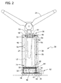
FIG. 2 is a front elevation schematic illustration of a cleaning apparatus in position to clean the turbine rotor blades of the wind turbine shown inFIG. 1 . -
FIG. 3 is a perspective schematic illustration of a turbine rotor blade that includes a plurality of spray nozzles for cleaning and/or de-icing the surface of the blade. - A method and apparatus for cleaning and/or de-icing the outer surface of wind turbine rotor blades is described below in detail. Spent cleaning solution used to clean and/or de-ice a rotor blade is collected, filtered, and reused to clean other rotor blades. The cleaning solution may be used to remove grime from the rotor blade and/or remove ice from the rotor blade. The cleaning apparatus is positioned so as to collect the spent cleaning solution for reuse. The apparatus includes an elliptical spray head that surrounds a portion of the rotor blade to permit cleaning all outer surfaces at once. The elliptical spray head is attached to lifting arms that move the spray head along the longitudinal axis of the rotor blade to permit cleaning of the outer surface along the length of the rotor blade. A cylindrical collection curtain may be attached to the elliptical spray head at one end and at the second end attached to a tank holding the cleaning solution to encircle the rotor blade and to direct the sprayed cleaning solution that does not land on the rotor blade back into the tank for reuse. Clean rotor blades increase the performance of the wind turbines and provide for increased annual energy production. In addition, the method and apparatus for cleaning and/or de-icing rotor blades facilitates improved life of the rotor blades, and maintains the aerodynamic shape of the blades. Further, by recycling the cleaning solution, the transportation cost of cleaning solution is reduced because a lower amount of cleaning solution for rotor blade maintenance is used. The use of the collection curtain facilitates capturing sprayed cleaning solution, even in moderate and high wind conditions, and directing a larger quantity of cleaning solution to the tank.
- Referring to the drawings,
FIG. 1 is a side elevation schematic illustration of awind turbine 10, such as, for example, a horizontal axis wind turbine.Wind turbine 10 includes atower 12 extending from a supportingsurface 14, anacelle 16 mounted on aframe 18 oftower 12, and arotor 20 coupled tonacelle 16.Rotor 20 includes ahub 22 and a plurality ofrotor blades 24 coupled tohub 22. In the exemplary embodiment,rotor 20 includes threerotor blades 24. In an alternative embodiment,rotor 20 includes more or less than threerotor blades 24. In the exemplary embodiment,tower 12 is fabricated from tubular steel and includes acavity 28 extending between supportingsurface 14 andnacelle 16. In an alternate embodiment,tower 12 is a lattice tower. - Various components of
wind turbine 10, in the exemplary embodiment, are housed innacelle 16 ontop tower 12 ofwind turbine 10. The height oftower 12 is selected based upon factors and conditions known in the art. In some configurations, one or more microcontrollers in a control system are used for overall system monitoring and control including pitch and speed regulation, high-speed shaft and yaw brake application, yaw and pump motor application and fault monitoring. Alternative distributed or centralized control architectures are used in alternate embodiments ofwind turbine 10. In the exemplary embodiment, the pitches ofblades 24 are controlled individually.Hub 22 andblades 24 together formwind turbine rotor 20. Rotation ofrotor 20 causes a generator to produce electrical power. - In use,
blades 24 are positioned aboutrotor hub 22 to facilitate rotatingrotor 20 to transfer kinetic energy from the wind into usable mechanical energy. As the wind strikesblades 24, and asblades 24 are rotated and subjected to centrifugal forces,blades 24 are subjected to various bending moments. As such,blades 24 deflect and/or rotate from a neutral, or non-deflected, position to a deflected position. Moreover, a pitch angle ofblades 24 can be changed by a pitching mechanism to facilitate increasing or decreasingblade 24 speed, and to facilitate reducingtower 12 strike. - Referring also to
FIG. 2 , a rotorblade cleaning apparatus 30 may be used to clean and/or de-ice the surfaces ofrotor blades 24 to remove ice and grime from, for example, dust, salt, dead insects, bird droppings, and other foreign substances. The buildup of grime and/or ice onrotor blades 24 can decrease the efficiency ofwind turbine 10. A comparative analysis of dirty rotor blades versus clean rotor blades shows that the annual energy production (AEP) of a wind turbine with dirty rotor blades may be from about 90% to about 98% of the AEP of a wind turbine with clean blades at annual mean wind speeds of 4 meters per second (m/s) to 11 m/s. Table I lists the results of this analysis.TABLE I Annual Mean Wind Speed (m/s) AEP from Clean Blade (MW·h) AEP from Dirty Blade (MW·h) Dirty Blade AEP as % of Clean Blade AEP % Difference 4.0 1152.8 1043.3 90.50 9.50 5.0 2221.5 2066.8 93.04 6.96 6.0 3441.6 3263.3 94.82 5.18 7.0 4636.1 4452.9 96.05 3.95 7.5 5180.3 4999.4 96.51 3.49 8.0 5672.7 5496.1 96.89 3.11 8.5 6104.9 5933.9 97.20 2.80 9.0 6472.4 6308.0 97.46 2.54 10.0 7010.6 6860.5 97.86 2.14 11.0 7305.6 7169.7 98.14 1.86 -
Cleaning apparatus 30, in an exemplary embodiment, includes atank 32, that holds acleaning solution 34, mounted on abase 36. In one embodiment,cleaning solution 34 removes grime fromrotor blades 24. In another embodiment, cleaningsolution 34 removes built-up ice fromrotor blades 24, and in still another embodiment, cleaningsolution 34 removes both grime and built-up ice fromrotor blades 24. Two liftingarms adjacent tank 32. Liftingarms hydraulic lifts arms base 36 and downwards towardsbase 36. In one embodiment, liftingarms hydraulic lifts arms hydraulic lifts Hydraulic lifts base 36 and liftingarms hydraulic lifts spray head 50 is attached to liftingarms attachment arms Elliptical spray head 50 includes anelliptical member 51 and a plurality ofspray nozzles 52 attached toelliptical member 51 thatspray cleaning solution 34 ontorotor blade 24 to clean the surface ofblade 24. Spraynozzles 52 are operatively coupled to at least one cleaningsolution feed pipe 54.Elliptical spray head 50 is sized so thatelliptical member 51 surrounds a portion ofrotor blade 24 which positionsspray nozzles 52 adjacent the surface ofrotor blade 24 for sprayingcleaning solution 34 ontorotor blade 24. - A
first end 56 ofpipe 54 is coupled toelliptical spray head 50 and asecond end 58 ofpipe 54 is coupled to apump 60 which is operatively coupled totank 32.Pipe 54 is a flexible pipe, a flexible hose, or a flexible tube.Pipe 54 can be formed from any suitable material, for example, braided stainless steel, rubber, plastic, or combinations thereof. -
Base 36 may be mounted on anysuitable vehicle 62 that is capable of transportingcleaning apparatus 30 towind turbine 10 for the cleaning and/or de-icing ofrotor blades 24. For example,base 36 may be mounted on a truck or a boat. In another embodiment,base 36 is the bed of a truck or the deck of a boat. - A
filtration device 64 is positioned over the top 66 oftank 32.Filtration device 64 includes at least onefilter pad 66 formed from afilter media 68. Any suitable filter media may be used, for example, woven and nonwoven fabrics, porous membranes, and the like.Filtration device 64 filters spent cleaningsolution 34 to permit recycling and reuse of cleaningsolution 34. Because of the ability to recyclecleaning solution 34, the total amount of cleaningsolution 34 needed to clean and/or de-icerotor blades 24 in a wind turbine farm is lowered, thereby lowering maintenance costs. - In one embodiment, cleaning
apparatus 30 also includes acollection curtain 70 to collect and redirect sprayedcleaning solution 34 back intotank 30.Collection curtain 70 has a cylindrical shape that encirclesrotor blade 24 when collection curtain is raised into position. Afirst end 72 ofcollection curtain 70 is attached toelliptical spray head 50 and asecond end 74 is attached totank 32. Collection curtain is moved intoposition encircling blade 24 whenelliptical spray head 50 is raised by liftingarms collection curtain 70 includes a plurality of accordion folds 76 that permitcollection curtain 70 to expand and contract like an accordion bellows when raised and lowered by liftingarms collection curtain 70 is returned totank 32.Collected cleaning solution 34 passes throughfiltration device 64 before enteringtank 32.Collection curtain 70 can be formed from a thin plastic sheet or a fabric made from any suitable material, for example, nylon, polyethylene, polyesters, polyamid, polyolefin, thermoplastic polyurethane, polyetherimide, polyphenyl ether, polyphenylene sulfide, polysulfone, aramid, and mixtures thereof. - To clean and/or de-ice
rotor blades 24 ofwind turbine 10,rotor blade 24 is positioned in a downward orientation substantially parallel to tower 12 and madeimmobile Cleaning apparatus 30 is positionedadjacent tower 12 and below therotor blade 24 withtank 32, containingcleaning solution 34, directly belowrotor blade 24. Liftingarms elliptical spray head 50 andcollection curtain 70 to a predetermined position along the longitudinal axis ofrotor blade 24.Cleaning solution 34 is pumped fromtank 32 toelliptical spray head 50 and sprayed thoughspray nozzles 52 onto an outer surface ofrotor blade 24. In one embodiment, cleaningsolution 34 is sprayed at a pressure of about 100 psi to about 7000 psi, in another embodiment, about 200 psi to about 5000 psi, and in another embodiment, about 200 psi to about 3000 psi.Elliptical spray head 50 is moved along the longitudinal axis ofrotor blade 24 while spraying cleaning solution onto the outer surface ofrotor blade 24 to clean and/or de-ice substantially the entire the length ofrotor blade 24. The spentcleaning solution 34 runs downrotor blade 24, drips off the end ofblade 24, passes throughfiltration device 64, and is collected intank 32 for reuse. In addition, sprayedcleaning solution 34 that does not land onrotor blade 24 is captured bycollection curtain 70 and is returned totank 32 after passing throughfiltration device 64. - In another embodiment, shown in
FIG. 3 ,rotor blade 24 includes a plurality ofspray nozzles 80 mounted along the length ofrotor blade 24. Spraynozzles 80 are operatively coupled to a cleaningsolution supply line 82 positioned withinrotor blade 24. Cleaningsolution supply line 82 extends between aroot 84 to atip 86 ofblade 24 and is coupled to cleaning solution feed pipe 54 (shown inFIG 2 ) to direct cleaningsolution 34 from tank 32 (shown inFIG. 2 ) tospray nozzles 80. - In addition,
spray nozzles 80 can be used to de-icerotor blade 24 by spraying heated fluid or heated gases throughspray nozzles 80. Rotor blade icing can be a problem at cold sites. De-icing of rotor blades is beneficial to mitigate the loads due to asymmetry of the rotor plane from the iced rotor blades. The fluid or gases can be heated by any known technique, for example, a heater attached to feedpipe 54, heating the fluid intank 32, or passing the fluid through the turbine gearbox radiator, or any other heat source. In one embodiment, the fluid or gases are heated to about 90°F to about 200°F, in another embodiment, about 100°F to about 160°F. - This written description uses examples to disclose the invention, including the preferred mode, and also to enable any person skilled in the art to practice the invention, including making and using any devices or systems and performing any incorporated methods. The patentable scope of the invention is defined by the claims, and may include other examples that occur to those skilled in the art. Such other examples are intended to be within the scope of the claims if they have structural elements that do not differ from the literal language of the claims, or if they include equivalent structural elements with insubstantial differences from the literal languages of the claims.
- Various aspects and embodiments of the present invention are defined by the following numbered clauses:
- 1. A method of applying a solution to a rotor blade of a wind turbine, the wind turbine comprising a tower and a plurality of rotor blades, said method comprising:
- positioning a rotor blade in an immobile position in a predetermined orientation;
- providing a tank containing a cleaning solution;
- positioning a plurality of lifting arms adjacent the rotor blade, the plurality of lifting arms attached to an elliptical spray head;
- connecting at least one pipe to the elliptical spray head and to a pump operatively coupled to the tank;
- raising the lifting arms to lift the elliptical spray head to a predetermined position along a longitudinal axis of the rotor blade;
- pumping cleaning solution from the tank to the elliptical spray head; and
- spraying the cleaning solution onto an outer surface of the rotor blade to clean the rotor blade.
- collecting the spent cleaning solution in the tank.
- 2. A method in accordance with Clause 1, further comprising moving the elliptical spray head along the longitudinal axis of the rotor blade while spraying the cleaning solution onto the outer surface of the rotor blade.
- 3. A method in accordance with any preceding Clause, wherein positioning a rotor blade in an immobile position in a predetermined orientation comprises positioning a rotor blade in an immobile position in a downward orientation substantially parallel to the tower, and providing a tank further comprises comprising positioning the tank directly below the rotor blade.
- 4. A method in accordance with any preceding Clause, further comprising collecting the spent cleaning solution in the tank.
- 5. A method in accordance with any preceding Clause, wherein the elliptical spray head comprises a plurality of spray nozzles.
- 6. A method in accordance with any preceding Clause, wherein the elliptical spray head is sized to surround a portion of the wind turbine rotor blade.
- 7. A method in accordance with any preceding Clause, wherein collecting the spent cleaning solution in the tank comprises filtering the spent cleaning solution through a filtering device, the filtering device comprising at least one filter pad comprising a filter media.
- 8. A method in accordance with any preceding Clause, further comprising mounting the tank and the plurality of lifting arms on a base.
- 9. A method in accordance with any preceding Clause, further comprising heating the cleaning solution.
- 10. A method in accordance with any preceding Clause, further comprising attaching a first end of a collection curtain to the elliptical spray head and a second end to the tank, the collection curtain having a cylindrical shape sized to encircle the rotor blade.
- 11. A method in accordance with any preceding Clause, wherein the collection curtain includes a plurality of accordion folds that permit the collection curtain to expand and contract.
- 12. A cleaning apparatus for cleaning at least one of grime and built-up ice off wind turbine rotor blades, said cleaning apparatus comprising:
- a tank mounted on a base;
- a plurality of lifting arms mounted on said base adjacent said tank;
- an elliptical spray head attached to said lifting arms, said lifting arms sized to lift said elliptical spray head from a first position to a second position, said second position farther away from said tank than said first position; and,
- at least one pipe, a first end of said pipe connected to said elliptical spray head, and a second end of said pipe operatively coupled to a pump, said pump operatively coupled to said tank.
- 13. A cleaning apparatus in accordance with any preceding Clause, wherein said elliptical spray head comprises a plurality of spray nozzles.
- 14. A cleaning apparatus in accordance with any preceding Clause, wherein said elliptical spray head is sized to surround a portion of a wind turbine rotor blade.
- 15. A cleaning apparatus in accordance with any preceding Clause, wherein said tank comprises a filtering device for filtering used cleaning solution.
- 16. A cleaning apparatus in accordance with any preceding Clause, wherein said filtering device comprises at least one filter pad comprising a filter media.
- 17. A cleaning apparatus in accordance with any preceding Clause, wherein said base is mounted on a vehicle, said vehicle comprising a truck, a trailer, or a boat.
- 18. A cleaning apparatus in accordance with any preceding Clause, further comprising a collection curtain attached at a first end of to said elliptical spray head and a second end to said tank, said collection curtain having a cylindrical shape sized to encircle said rotor blade.
- 19. A cleaning apparatus in accordance with any preceding Clause, wherein said collection curtain comprises a plurality of accordion folds that permit said collection curtain to expand and contract.
- 20. A cleaning apparatus in accordance with any preceding Clause, further comprising a plurality of spray nozzles mounted along a length of a wind turbine rotor blade, said spray nozzles operatively coupled to a feed line extending through said rotor blade, said feed line operatively coupled to said at least one pipe.
Claims (9)
- A cleaning apparatus (30) for cleaning at least one of grime and built-up ice off wind turbine rotor blades (24), said cleaning apparatus comprising:a tank (32) mounted on a base (36);a plurality of lifting arms (38,40) mounted on said base adjacent said tank;an elliptical spray head (50) attached to said lifting arms, said lifting arms sized to lift said elliptical spray head from a first position to a second position, said second position farther away from said tank than said first position; and,at least one pipe (54), a first end (56) of said pipe connected to said elliptical spray head, and a second end of said pipe operatively coupled to a pump (60), said pump operatively coupled to said tank.
- A cleaning apparatus (30) in accordance with claim 1, wherein said elliptical spray head (50) comprises a plurality of spray nozzles (52).
- A cleaning apparatus (30) in accordance with any preceding claim, wherein said elliptical spray (50) head is sized to surround a portion of a wind turbine rotor blade (24).
- A cleaning apparatus (30) in accordance with any preceding claim, wherein said tank (32) comprises a filtering device (64) for filtering used cleaning solution (34).
- A cleaning apparatus (30) in accordance with any preceding claim, wherein said filtering device (64) comprises at least one filter pad (66) comprising a filter media (68).
- A cleaning apparatus (30) in accordance with any preceding claim, wherein said base (36) is mounted on a vehicle (62), said vehicle comprising a truck, a trailer, or a boat.
- A cleaning apparatus (30) in accordance with any preceding claim, further comprising a collection curtain (70) attached at a first end (56) of to said elliptical spray head (50) and a second end (58) to said tank (32), said collection curtain having a cylindrical shape sized to encircle said rotor blade (24).
- A cleaning apparatus (30) in accordance with any preceding claim, wherein said collection curtain (70) comprises a plurality of accordion folds (76) that permit said collection curtain to expand and contract.
- A cleaning apparatus (30) in accordance with any preceding claim, further comprising a plurality of spray nozzles (52) mounted along a length of a wind turbine rotor blade (24), said spray nozzles operatively coupled to a feed line extending through said rotor blade, said feed line operatively coupled to said at least one pipe (54).
Applications Claiming Priority (1)
| Application Number | Priority Date | Filing Date | Title |
|---|---|---|---|
| US12/485,492 US8062431B2 (en) | 2009-06-16 | 2009-06-16 | Method and apparatus for cleaning and de-icing wind turbine rotor blades |
Publications (2)
| Publication Number | Publication Date |
|---|---|
| EP2278158A2 true EP2278158A2 (en) | 2011-01-26 |
| EP2278158A3 EP2278158A3 (en) | 2015-08-19 |
Family
ID=42221680
Family Applications (1)
| Application Number | Title | Priority Date | Filing Date |
|---|---|---|---|
| EP10165036.4A Withdrawn EP2278158A3 (en) | 2009-06-16 | 2010-06-07 | Method and apparatus for cleaning and de-icing wind turbine rotor blades |
Country Status (4)
| Country | Link |
|---|---|
| US (1) | US8062431B2 (en) |
| EP (1) | EP2278158A3 (en) |
| CN (1) | CN101920252B (en) |
| CA (1) | CA2705982A1 (en) |
Cited By (2)
| Publication number | Priority date | Publication date | Assignee | Title |
|---|---|---|---|---|
| KR101422707B1 (en) * | 2012-08-08 | 2014-07-23 | 삼성중공업 주식회사 | Apparatus for preventing or removing icing and wind power generator including the same |
| CN110953129A (en) * | 2019-12-12 | 2020-04-03 | 余姚心智新能源科技有限公司 | Wind motor blade cleaning device |
Families Citing this family (48)
| Publication number | Priority date | Publication date | Assignee | Title |
|---|---|---|---|---|
| US8347899B2 (en) * | 2009-10-20 | 2013-01-08 | Jensen dustin | Wind turbine fluid application apparatus |
| NL2004871C2 (en) * | 2010-06-10 | 2011-12-13 | Special Blade Service B V | MAIN WORKER FOR WIND TURBINES. |
| US8544484B2 (en) | 2010-06-23 | 2013-10-01 | Dustin Jensen | Wind turbine blade treatment apparatuses and methods |
| ES2381351B1 (en) * | 2010-10-29 | 2012-12-13 | Servicios De Ingeniería Y Montaje Alen S.L. | CLEANING PROCEDURE OF AIRLINER SHOES. |
| US8347900B2 (en) * | 2011-04-05 | 2013-01-08 | Jensen dustin | Wind turbine fluid application apparatus |
| US20140034418A1 (en) * | 2011-04-14 | 2014-02-06 | Mantenimientos Electricos Campo De Aviacion, S.L. | Repair/cleaning scaffolding tower for wind turbines |
| CN102213191A (en) * | 2011-05-20 | 2011-10-12 | 叶卫 | Device and method for preventing rotor blade of wind driven generator from freezing |
| CN102322405B (en) * | 2011-08-16 | 2013-03-06 | 国电联合动力技术有限公司 | Deicing and freeze resisting system for blade of wind generating set |
| US9574549B2 (en) | 2011-09-02 | 2017-02-21 | Samsung Heavy Ind. Co., Ltd. | Blade maintenance device for wind turbine |
| KR101390851B1 (en) | 2012-06-27 | 2014-05-08 | 삼성중공업 주식회사 | Blade maintenance platform for wind turbine |
| US9527116B2 (en) * | 2013-09-28 | 2016-12-27 | General Electric Company | System and method for conformal cleaning |
| NO20141141A1 (en) * | 2014-09-19 | 2016-02-29 | Multi Solutions As | Procedure and system for cleaning cooling pipes in heat exchangers |
| CN104438177B (en) * | 2014-11-11 | 2016-08-17 | 沈阳黎明航空发动机(集团)有限责任公司 | A kind of cleaning chuck of high vortex blade inner chamber residual fluorescence liquid cleaning |
| DE102015002015A1 (en) | 2015-02-20 | 2016-08-25 | Senvion Gmbh | Rotor blade deicing apparatus and method for deicing a rotor blade |
| ES2603434B1 (en) * | 2015-08-17 | 2017-12-22 | Gamesa Innovation & Technology, S.L. | External cleaning machine in wind turbine towers |
| ES2947045T3 (en) * | 2015-10-09 | 2023-07-31 | Vestas Wind Sys As | Wind turbine blade surface treatment apparatus and method |
| CN105443325A (en) * | 2015-12-08 | 2016-03-30 | 远景能源(江苏)有限公司 | Ice melting device and method for wind generating set |
| CN106014881B (en) * | 2016-07-06 | 2018-10-23 | 国电联合动力技术有限公司 | A kind of blade of wind-driven generator cleaning device |
| EP3485162A1 (en) * | 2016-07-12 | 2019-05-22 | Rope Robotics APS | System with art apparatus on a wire, method of its. operation, use therof and a toolkit |
| ES2858321T3 (en) * | 2016-09-14 | 2021-09-30 | Vestas Wind Sys As | Apparatus for movement along a tower structure |
| US10690120B2 (en) | 2016-09-28 | 2020-06-23 | Sonny K. Fraughton | Cleaning apparatuses |
| EP3312418B1 (en) * | 2016-10-20 | 2019-09-11 | LM WP Patent Holding A/S | A method and system for performing maintenance such as de-icing of a rotor blade of a wind turbine rotor |
| US10648456B2 (en) | 2016-10-21 | 2020-05-12 | General Electric Company | Organic conductive elements for deicing and lightning protection of a wind turbine rotor blade |
| ES2956735T3 (en) * | 2017-02-27 | 2023-12-27 | Lebo Robotics Inc | Procedure to perform maintenance on a wind turbine blade |
| US10377968B2 (en) | 2017-06-12 | 2019-08-13 | General Electric Company | Cleaning compositions and methods for removing oxides from superalloy substrates |
| CN108087216B (en) * | 2017-12-19 | 2019-12-13 | 北京金风科创风电设备有限公司 | Cleaning device, blade, wind power generating set and blade cleaning method |
| CN108480246B (en) * | 2018-04-11 | 2021-06-01 | 杭州启澄科技有限公司 | Method for cleaning blade of wind driven generator |
| CN109013441B (en) * | 2018-09-04 | 2020-10-09 | 苏州乐赢科技咨询有限公司 | A height-adjustable wind cleaning device |
| CN109107939B (en) * | 2018-09-04 | 2020-11-17 | 苏州市相城区阳澄产业园发展有限公司 | Convenient wind-force cleaning device who dismantles |
| US11525435B2 (en) | 2018-09-17 | 2022-12-13 | Pp Energy Aps | Water intrusion prevention system for turbine blades |
| US11020772B2 (en) | 2019-02-05 | 2021-06-01 | William F. Crunk | System and method for cleaning wind turbine blades and solar panels |
| CN109899250B (en) * | 2019-03-04 | 2020-12-22 | 江苏大墩子银杏生物科技有限公司 | Wind-driven generator |
| CN110273820B (en) * | 2019-06-24 | 2020-12-08 | 南京河海南自水电自动化有限公司 | Wind driven generator blade cleaning equipment for power generation equipment |
| CN110397559B (en) * | 2019-07-03 | 2020-12-04 | 江西虔研科技咨询有限公司 | A long-life wind turbine with protective function |
| CN110307122B (en) * | 2019-07-23 | 2021-05-04 | 国电电力诸城风力发电有限公司 | A safe and reliable wind power generation device with cleaning function |
| CN110863959B (en) * | 2019-12-12 | 2021-01-05 | 辽宁大唐国际新能源有限公司 | Deicing device for turbine blade of wind turbine |
| CN111059006B (en) * | 2019-12-20 | 2022-12-09 | 大唐郏县风力发电有限责任公司 | Large-scale wind motor blade washs maintenance equipment |
| CN111794919B (en) * | 2020-07-13 | 2021-10-29 | 三一重能有限公司 | Wind driven generator blade deicing equipment and wind driven generator blade deicing method |
| EP3995693A1 (en) | 2020-11-10 | 2022-05-11 | PP Energy ApS | Temporary enclosure for at least a part of a rotor blade |
| CN112539144B (en) * | 2020-12-25 | 2022-05-13 | 大连理工江苏研究院有限公司 | Intelligent anti-freezing wind power generation device |
| CN112958521B (en) * | 2021-02-03 | 2022-08-23 | 盐城国丰海上风力发电有限公司 | Large-scale power generation fan blade cleaning system |
| CN112901430B (en) * | 2021-04-06 | 2022-06-07 | 兰州理工大学 | Climb-assisting type deformable wind power blade deicing special equipment |
| ES3017139T3 (en) * | 2022-01-24 | 2025-05-12 | Pp Energy Aps | Wind turbine blade maintenance platform |
| CN114718823B (en) * | 2022-05-13 | 2023-03-31 | 国家电投集团广西兴安风电有限公司 | Be used for wind turbine generator system icing deicing device for monitoring |
| CN117052614B (en) * | 2023-10-12 | 2024-01-19 | 国网山西省电力公司运城供电公司 | Wind turbine generator operation maintenance equipment and working method |
| CN117231446B (en) * | 2023-10-23 | 2024-06-14 | 中节能风力发电股份有限公司 | Wind turbine generator set outer surface cleaning system and method |
| CN118728667A (en) * | 2024-08-08 | 2024-10-01 | 内蒙古圣龙大地科技有限公司 | A wind turbine blade leading edge cleaning, recycling and reuse device |
| WO2026009043A1 (en) * | 2025-03-08 | 2026-01-08 | Gamiy Oleg | Windmotor and method for its operating |
Family Cites Families (9)
| Publication number | Priority date | Publication date | Assignee | Title |
|---|---|---|---|---|
| CA2341398A1 (en) * | 1998-09-22 | 2000-03-30 | Antonius Siebert | Device for carrying out repair and service work especially on the rotor blades of wind turbine generators |
| EP1583905B1 (en) * | 2001-12-06 | 2010-04-28 | PP Energy ApS | Method and apparatus for treatment of a rotor blade on a windmill |
| AU2003258492A1 (en) | 2002-09-04 | 2004-03-29 | Pp Energy Aps | A method and a device for lifting and/or lowering of objects at a wind turbine or the like and uses hereof |
| ITTO20020908A1 (en) * | 2002-10-17 | 2004-04-18 | Lorenzo Battisti | ANTI-ICE SYSTEM FOR WIND SYSTEMS. |
| DE10311674B4 (en) * | 2003-03-11 | 2007-02-01 | aeroconcept Ingenieurgesellschaft für Luftfahrttechnik und Faserverbundtechnologie mbH | maintenance platform |
| US6890152B1 (en) * | 2003-10-03 | 2005-05-10 | General Electric Company | Deicing device for wind turbine blades |
| WO2005054672A1 (en) * | 2003-12-04 | 2005-06-16 | Pp Energy Aps | Method and apparatus for treatment of a part of a wind turbine |
| US7217091B2 (en) * | 2004-07-20 | 2007-05-15 | General Electric Company | Methods and apparatus for deicing airfoils or rotor blades |
| DK176133B1 (en) * | 2004-12-21 | 2006-09-18 | Lm Glasfiber As | Offshore wind turbine with ice fighting device |
-
2009
- 2009-06-16 US US12/485,492 patent/US8062431B2/en not_active Expired - Fee Related
-
2010
- 2010-06-03 CA CA2705982A patent/CA2705982A1/en not_active Abandoned
- 2010-06-07 EP EP10165036.4A patent/EP2278158A3/en not_active Withdrawn
- 2010-06-11 CN CN2010102085858A patent/CN101920252B/en not_active Expired - Fee Related
Non-Patent Citations (1)
| Title |
|---|
| None |
Cited By (2)
| Publication number | Priority date | Publication date | Assignee | Title |
|---|---|---|---|---|
| KR101422707B1 (en) * | 2012-08-08 | 2014-07-23 | 삼성중공업 주식회사 | Apparatus for preventing or removing icing and wind power generator including the same |
| CN110953129A (en) * | 2019-12-12 | 2020-04-03 | 余姚心智新能源科技有限公司 | Wind motor blade cleaning device |
Also Published As
| Publication number | Publication date |
|---|---|
| CN101920252B (en) | 2013-07-31 |
| CN101920252A (en) | 2010-12-22 |
| CA2705982A1 (en) | 2010-12-16 |
| US20100132738A1 (en) | 2010-06-03 |
| EP2278158A3 (en) | 2015-08-19 |
| US8062431B2 (en) | 2011-11-22 |
Similar Documents
| Publication | Publication Date | Title |
|---|---|---|
| US8062431B2 (en) | Method and apparatus for cleaning and de-icing wind turbine rotor blades | |
| US7521083B2 (en) | Method and apparatus for treatment of a rotor blade on a windmill | |
| EP2281770A2 (en) | Tower climbing and servicing device | |
| KR101358125B1 (en) | Maintenance apparatus for wind turbine | |
| KR101720561B1 (en) | A Cleaning System for Wind Turbine Blade | |
| EP3418555A1 (en) | Positioning assembly for a wind turbine rotor blade lifting device | |
| US20120003089A1 (en) | Cleaning and inspecting apparatus for wind turbine and related methods | |
| KR101422497B1 (en) | Blade maintenance platform for wind turbine | |
| KR101324979B1 (en) | Blade maintenance platform for wind turbine | |
| CN117552923B (en) | A wind turbine | |
| WO2011107087A2 (en) | Rotor blade cleaner | |
| CN106089602A (en) | A kind of blower fan tower barrel clean and maintenance platform | |
| KR20140001412A (en) | Blade maintenance platform for wind turbine | |
| CN114614736B (en) | Photovoltaic power station with bird repellent structure | |
| CN218598304U (en) | Wind power generation blade cleaning device | |
| CN212642967U (en) | Fan tower barrel maintenance device | |
| CN219817405U (en) | Photovoltaic module washs car | |
| CN104815806A (en) | Wind-power net cage cleaning device | |
| CN111894819A (en) | Wind turbine generator system blade maintenance device | |
| CN210531073U (en) | Suspension bridge for maintaining wind power blade | |
| CN119276210A (en) | A photovoltaic charging device for energy-saving inland electric extended-range cargo ships | |
| CN217789629U (en) | Multipurpose inspection equipment for solar power station | |
| CN223241563U (en) | Blade deicing equipment for wind power generation | |
| CN212583886U (en) | Wind-powered electricity generation blade is with clean structure fast | |
| CN116159837A (en) | Automatic belt cleaning device of on-vehicle photovoltaic module |
Legal Events
| Date | Code | Title | Description |
|---|---|---|---|
| PUAI | Public reference made under article 153(3) epc to a published international application that has entered the european phase |
Free format text: ORIGINAL CODE: 0009012 |
|
| AK | Designated contracting states |
Kind code of ref document: A2 Designated state(s): AL AT BE BG CH CY CZ DE DK EE ES FI FR GB GR HR HU IE IS IT LI LT LU LV MC MK MT NL NO PL PT RO SE SI SK SM TR |
|
| AX | Request for extension of the european patent |
Extension state: BA ME RS |
|
| PUAL | Search report despatched |
Free format text: ORIGINAL CODE: 0009013 |
|
| AK | Designated contracting states |
Kind code of ref document: A3 Designated state(s): AL AT BE BG CH CY CZ DE DK EE ES FI FR GB GR HR HU IE IS IT LI LT LU LV MC MK MT NL NO PL PT RO SE SI SK SM TR |
|
| AX | Request for extension of the european patent |
Extension state: BA ME RS |
|
| RIC1 | Information provided on ipc code assigned before grant |
Ipc: B08B 3/04 20060101ALI20150714BHEP Ipc: F03D 1/00 20060101AFI20150714BHEP Ipc: B08B 17/00 20060101ALI20150714BHEP Ipc: B08B 17/02 20060101ALI20150714BHEP Ipc: F03D 11/00 20060101ALI20150714BHEP Ipc: B08B 3/02 20060101ALI20150714BHEP |
|
| 17P | Request for examination filed |
Effective date: 20160219 |
|
| RBV | Designated contracting states (corrected) |
Designated state(s): AL AT BE BG CH CY CZ DE DK EE ES FI FR GB GR HR HU IE IS IT LI LT LU LV MC MK MT NL NO PL PT RO SE SI SK SM TR |
|
| GRAP | Despatch of communication of intention to grant a patent |
Free format text: ORIGINAL CODE: EPIDOSNIGR1 |
|
| RIC1 | Information provided on ipc code assigned before grant |
Ipc: F03D 80/00 20160101ALN20160622BHEP Ipc: B08B 3/02 20060101ALI20160622BHEP Ipc: F03D 80/40 20160101ALN20160622BHEP Ipc: F03D 1/00 20060101AFI20160622BHEP Ipc: B08B 17/02 20060101ALI20160622BHEP Ipc: B08B 17/00 20060101ALI20160622BHEP Ipc: B08B 3/04 20060101ALI20160622BHEP Ipc: F03D 80/55 20160101ALN20160622BHEP |
|
| INTG | Intention to grant announced |
Effective date: 20160708 |
|
| STAA | Information on the status of an ep patent application or granted ep patent |
Free format text: STATUS: THE APPLICATION IS DEEMED TO BE WITHDRAWN |
|
| 18D | Application deemed to be withdrawn |
Effective date: 20161119 |