EP2277481A2 - Dispositif laser pour la chirurgie ophtalmique - Google Patents
Dispositif laser pour la chirurgie ophtalmique Download PDFInfo
- Publication number
- EP2277481A2 EP2277481A2 EP10008851A EP10008851A EP2277481A2 EP 2277481 A2 EP2277481 A2 EP 2277481A2 EP 10008851 A EP10008851 A EP 10008851A EP 10008851 A EP10008851 A EP 10008851A EP 2277481 A2 EP2277481 A2 EP 2277481A2
- Authority
- EP
- European Patent Office
- Prior art keywords
- lens
- eye
- applanation
- cornea
- applanation lens
- Prior art date
- Legal status (The legal status is an assumption and is not a legal conclusion. Google has not performed a legal analysis and makes no representation as to the accuracy of the status listed.)
- Granted
Links
Images

Classifications
-
- A—HUMAN NECESSITIES
- A61—MEDICAL OR VETERINARY SCIENCE; HYGIENE
- A61F—FILTERS IMPLANTABLE INTO BLOOD VESSELS; PROSTHESES; DEVICES PROVIDING PATENCY TO, OR PREVENTING COLLAPSING OF, TUBULAR STRUCTURES OF THE BODY, e.g. STENTS; ORTHOPAEDIC, NURSING OR CONTRACEPTIVE DEVICES; FOMENTATION; TREATMENT OR PROTECTION OF EYES OR EARS; BANDAGES, DRESSINGS OR ABSORBENT PADS; FIRST-AID KITS
- A61F9/00—Methods or devices for treatment of the eyes; Devices for putting in contact-lenses; Devices to correct squinting; Apparatus to guide the blind; Protective devices for the eyes, carried on the body or in the hand
- A61F9/007—Methods or devices for eye surgery
- A61F9/008—Methods or devices for eye surgery using laser
- A61F9/009—Auxiliary devices making contact with the eyeball and coupling in laser light, e.g. goniolenses
-
- A—HUMAN NECESSITIES
- A61—MEDICAL OR VETERINARY SCIENCE; HYGIENE
- A61F—FILTERS IMPLANTABLE INTO BLOOD VESSELS; PROSTHESES; DEVICES PROVIDING PATENCY TO, OR PREVENTING COLLAPSING OF, TUBULAR STRUCTURES OF THE BODY, e.g. STENTS; ORTHOPAEDIC, NURSING OR CONTRACEPTIVE DEVICES; FOMENTATION; TREATMENT OR PROTECTION OF EYES OR EARS; BANDAGES, DRESSINGS OR ABSORBENT PADS; FIRST-AID KITS
- A61F9/00—Methods or devices for treatment of the eyes; Devices for putting in contact-lenses; Devices to correct squinting; Apparatus to guide the blind; Protective devices for the eyes, carried on the body or in the hand
- A61F9/007—Methods or devices for eye surgery
- A61F9/008—Methods or devices for eye surgery using laser
- A61F9/00825—Methods or devices for eye surgery using laser for photodisruption
- A61F9/00827—Refractive correction, e.g. lenticle
-
- A—HUMAN NECESSITIES
- A61—MEDICAL OR VETERINARY SCIENCE; HYGIENE
- A61F—FILTERS IMPLANTABLE INTO BLOOD VESSELS; PROSTHESES; DEVICES PROVIDING PATENCY TO, OR PREVENTING COLLAPSING OF, TUBULAR STRUCTURES OF THE BODY, e.g. STENTS; ORTHOPAEDIC, NURSING OR CONTRACEPTIVE DEVICES; FOMENTATION; TREATMENT OR PROTECTION OF EYES OR EARS; BANDAGES, DRESSINGS OR ABSORBENT PADS; FIRST-AID KITS
- A61F9/00—Methods or devices for treatment of the eyes; Devices for putting in contact-lenses; Devices to correct squinting; Apparatus to guide the blind; Protective devices for the eyes, carried on the body or in the hand
- A61F9/007—Methods or devices for eye surgery
- A61F9/008—Methods or devices for eye surgery using laser
- A61F2009/00861—Methods or devices for eye surgery using laser adapted for treatment at a particular location
- A61F2009/00872—Cornea
-
- A—HUMAN NECESSITIES
- A61—MEDICAL OR VETERINARY SCIENCE; HYGIENE
- A61F—FILTERS IMPLANTABLE INTO BLOOD VESSELS; PROSTHESES; DEVICES PROVIDING PATENCY TO, OR PREVENTING COLLAPSING OF, TUBULAR STRUCTURES OF THE BODY, e.g. STENTS; ORTHOPAEDIC, NURSING OR CONTRACEPTIVE DEVICES; FOMENTATION; TREATMENT OR PROTECTION OF EYES OR EARS; BANDAGES, DRESSINGS OR ABSORBENT PADS; FIRST-AID KITS
- A61F9/00—Methods or devices for treatment of the eyes; Devices for putting in contact-lenses; Devices to correct squinting; Apparatus to guide the blind; Protective devices for the eyes, carried on the body or in the hand
- A61F9/007—Methods or devices for eye surgery
- A61F9/008—Methods or devices for eye surgery using laser
- A61F9/00802—Methods or devices for eye surgery using laser for photoablation
-
- A—HUMAN NECESSITIES
- A61—MEDICAL OR VETERINARY SCIENCE; HYGIENE
- A61F—FILTERS IMPLANTABLE INTO BLOOD VESSELS; PROSTHESES; DEVICES PROVIDING PATENCY TO, OR PREVENTING COLLAPSING OF, TUBULAR STRUCTURES OF THE BODY, e.g. STENTS; ORTHOPAEDIC, NURSING OR CONTRACEPTIVE DEVICES; FOMENTATION; TREATMENT OR PROTECTION OF EYES OR EARS; BANDAGES, DRESSINGS OR ABSORBENT PADS; FIRST-AID KITS
- A61F9/00—Methods or devices for treatment of the eyes; Devices for putting in contact-lenses; Devices to correct squinting; Apparatus to guide the blind; Protective devices for the eyes, carried on the body or in the hand
- A61F9/007—Methods or devices for eye surgery
- A61F9/008—Methods or devices for eye surgery using laser
- A61F9/00825—Methods or devices for eye surgery using laser for photodisruption
- A61F9/00836—Flap cutting
Definitions
- the invention relates to a laser device for ophthalmological surgery, with a laser radiation source providing pulsed laser radiation and means for coupling the laser radiation into an ocular treatment site, wherein the coupling means comprise an applanation lens to be placed on an eye surface.
- Pulsed laser radiation is used in ophthalmic surgery, for example, to apply corneal (corneal) incisions or to ablate material from the surface of the cornea.
- the irradiated laser radiation causes a photodisruptive process in the corneal tissue, which leads to tissue separation or to the evaporation of tissue material.
- Such treatments of the cornea take place, for example, in the context of refractive methods for the reduction or complete correction of refractive errors of the eye, in which the cornea is reshaped and thereby its refractive properties are changed.
- LASIK Laser Keratomileusis
- a lid is cut out of the corneal epithelium either mechanically (by means of an oscillating cutting blade in a so-called microkeratome) or optically (by means of laser radiation), which still hangs on the cornea in part of its edge.
- this lid usually referred to as a flap, is folded to the side, whereby the underlying stroma becomes accessible.
- laser radiation stromal tissue is then removed in accordance with a previously determined for each patient ablation. The flap is then folded back, allowing the wound to heal relatively quickly.
- laser radiation of different wavelengths and / or pulse durations is used in laser-optical eye surgery.
- NIR low infrared
- pulse durations in the femtosecond range or in the low picosecond range are customary to use in the low infrared (NIR) wavelength range, for example between 1000 and 1100 nm, with pulse durations in the femtosecond range or in the low picosecond range.
- the photoablation of stromal tissue usually laser radiation in the ultraviolet wavelength range, for example 193 nm or 347 nm, the pulse durations used can also be longer, down to the nanosecond range.
- fixation device For a precise coupling of the laser radiation in the eye, it is known to fix the eye by means of a fixation device, which is sucked by vacuum on the eye.
- the fixation device comprises an applanation lens serving as a distal coupling element for the laser radiation, which comes to rest in direct contact with the ocular surface when the fixation device is aspirated.
- the applanation lens creates a defined, stable interface between the eye and the laser system. Examples of fixation devices and applanation lenses can be found in US 2002/0103481 A1 . EP 0 608 052 A2 . EP 0 993 814 A1 and US 5,549,632 ,
- Previous applanation lenses extend over large areas of the cornea and sit unmoving on the cornea. They are available in many different forms. By sucking the fixation device, they are pressed against the eye so that the cornea deforms and clings flat to the lens. Particularly in the case of plane-parallel applanation lenses and convexly curved lenses, a comparatively high biomechanical load is exerted on the cornea. In addition, the intraocular pressure is comparatively greatly increased by the deformation of the eye. There are also known applanation lenses with a concave, rotationally symmetrical contact surface on their side facing the eye, both with spherical and with aspheric curvature. Although the biomechanical loading of the cornea and the increased intraocular pressure can be alleviated with both concave lens variants. However, further improvements are needed in this regard.
- the object of the invention is therefore to specify geometries for applanation lenses, which allow a further reduction of the intraocular pressure and the corneal load.
- the applanation lens has an at least approximately bitorische contact surface on its side facing the eye.
- the applanation lens is configured as a rod lens, wherein the applanation lens is associated with movement drive means for moving the applanation lens over the ocular surface.
- the first aspect makes use of the knowledge that the corneal surface of the human eye is not rotationally symmetrical but has different curvature along different meridians.
- the corneal surface can be modeled in good approximation and with good generality by a bitoric surface which has different radii of curvature in two mutually perpendicular meridian sections and is aspheric in both meridian directions.
- a bitoric surface which has different radii of curvature in two mutually perpendicular meridian sections and is aspheric in both meridian directions.
- the contact surface of the applanation lens according to the invention can be modeled, for example, this formula. It is understood that the contact surface of the applanation lens does not have to be exactly bitoric in the strictly mathematical sense as long as it has aspherical contours with different radii of curvature in two transverse (not necessarily exactly perpendicular) meridional directions.
- the contact surface of the applanation lens may, for example, be formed on the basis of data obtained by measuring the corneal surface of one or more persons. Thus, for example, the applanation lens can be made individually for each patient or the data of a large number of persons can be converted into one or more standard lenses.
- the cornea Due to the better adaptation of the contact surface of the lens to the actual shape of the corneal surface, the cornea must deform less so as to conform perfectly to the contact surface. Therefore, their biomechanical load is lower and also the intraocular pressure does not increase so much.
- the applanation lens used is a rod lens which can be moved over the cornea by means of its associated movement drive means.
- the movable support allows the rod lens to be in contact with the ocular surface only in a relatively small local area.
- By moving the rod lens over the cornea a larger area of the eye surface can be swept over, so that even with a rod lens larger areas of the eye, especially the cornea, can be processed.
- the small-surface contact with the ocular surface leads to the fact that the cornea is only locally deformed and loaded, which has a favorable effect on the total biomechanical load of the cornea and the intraocular pressure.
- the movement driving means may be adapted to move the rod lens transversely to its longitudinal direction substantially linearly over the cornea. Alternatively or additionally, they may be adapted to rotate the rod lens about a lens vertical axis in order thereby to be able to cover larger areas of the corneal surface.
- the rod lens When viewed in a section transverse to the rod longitudinal direction, the rod lens preferably has a convexly rounded contact surface for the abutment with the cornea.
- the curvature of this contact surface may be spherical or aspherical.
- the contact surface of the lens When viewed along the rod longitudinal direction, the contact surface of the lens may be substantially rectilinear.
- the contact surface of the rod lens is concavely curved in view of the curvature of the corneal surface when viewed along its rod longitudinal direction, for example in at least approximately correspondence to the curvature of the corneal surface in one of the two main meridian directions.
- the invention further provides an applanation lens for use in a laser device according to one of the above-described two modes.
- the applanation lens has an at least approximately bitoric contact surface or, in the case of a design as a rod lens, a convex-cylindrical contact surface on a lens side intended for contact with an ocular surface. Based on empirical data that can be obtained by surveying the corneal surface of a large number of individuals, it is possible to make a set of applanation lenses that differ in their radii of curvature and / or different asphericities of their interface.
- FIG. 1 a human eye 10 is schematically indicated, the cornea is processed with a laser device 12, for example, to produce a flap section in the context of a LASIK treatment.
- the laser device 12 comprises a laser radiation source 14, which generates pulsed laser radiation in the NIR or UV wavelength range.
- the pulse duration of the laser radiation generated is in the range of femtoseconds, but it can also be in the pico or even in the nanosecond range.
- the laser radiation source 14 may include, for example, a fiber laser, a solid-state laser or an excimer laser. Limitations on the type of the laser radiation source 14, the wavelength of the laser radiation generated by it and the pulse lengths are not intended in the context of the invention.
- the radiation pulses provided by the laser radiation source 14 are conducted via a beam guiding arrangement 16 to a coupling-in unit 18, by means of which the pulses are coupled into the cornea of the eye 10.
- the coupling-in unit 18 comprises fixing means by means of which the coupling-in unit 18 or at least one eye-near part thereof can be fixed to the eye 10 by vacuum suction.
- the fixing means have a preferably annular suction chamber 20, which is closed when placing the coupling unit 18 on the eye 10 through the eye surface and is connected in a manner not shown to a vacuum pump.
- the fixation of the eye by suction of a fixation component is known per se in the art, which is why details of the fixation means of the coupling unit 18 need not be discussed here.
- the beam guiding arrangement 16 or / and the coupling-in unit 18 furthermore contain deflection means (usually referred to as scanners), not shown in more detail, in order to prevent the Laser radiation over a target area to be processed to move away, and focusing means for focusing the injected into the eye 10 radiation to a target point (focus).
- deflection means usually referred to as scanners
- focusing means for focusing the injected into the eye 10 radiation to a target point (focus).
- Such deflecting and focusing means are well known in the art. A more detailed description of these components can therefore be omitted here.
- the coupling-in unit 18 contains an applanation lens 22 which, in the course of fixing the coupling-in unit 18, reaches the eye 10 for support on the surface of the cornea.
- the Applanationslinse has on its side facing an in FIG. 1 24 designated contact surface, which is formed in an embodiment in approximate adaptation to the actual contour of the human corneal surface is substantially bitorisch.
- the applanation lens 22 extends over the entire area of the cornea to be processed; she sits motionless on the cornea during the operation.
- the applanation lens is a rod lens
- the contact surface is round-convex when viewed in a section transverse to the rod longitudinal direction.
- the rod lens may be a cylindrical lens, which extends in the direction of its longitudinal extent substantially rectilinear.
- the rod lens is indicated at 22 '. Due to its comparatively small-area contact area with the corneal surface of the eye 10, it is movably arranged in the coupling-in unit 18, wherein a motor, for example electromotive or piezomotor, drive unit 25 is provided for driving the rod lens 22 ', which is driven by a suitable drive connection (indicated at 26). drivingly coupled or couplable with the rod lens 22 '.
- a motor for example electromotive or piezomotor
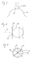
- FIG. 2 shows the eye 10 in an enlarged view obliquely from the front.
- the cornea is indicated at 28.
- its surface does not have an exact spherical contour, but rather an approximate bitoric shape.
- Bitterness means that the corneal surface runs along each of two main meridians that run transversely to one another aspherically, each with a different radius of curvature.
- the two meridians are in FIG. 2 dashed lines and designated 30, 32.
- the angle between the two meridians 30, 32 is often not exactly 90 degrees. Nevertheless, it has been shown that the human surface of the cornea can be mathematically well modeled by a bitorus surface with mutually perpendicular meridians.
- the meridians of the contact surface 24 are preferably perpendicular to one another. It is certainly not excluded, for even better adaptation to the actual conditions of the human corneal surface, for example, depending on the particular patient, the meridians of the bitorischen contact surface 24 is not exactly perpendicular to each other, but for example at an angle of 85 degrees or another angle other than 90 degrees.
- FIG. 3 shows the applanation lens 22 schematically in a state in which it is placed on the cornea 28 of the eye 10.
- the sectional view of the FIG. 3 shows the course of the contact surface 24 along the meridian larger radius of curvature.
- the 90 degree rotated sectional view of the FIG. 4 shows the course of the contact surface 24 along the meridian smaller radius of curvature.
- the asphericity of the contact surface 24 in the two meridian directions may be the same or different.
- the applanation lens 22 On its side facing away from the eye, the applanation lens 22 is in the FIGS. 3 and 4 shown with a convex curved shape. Other geometries of the eye-facing lens side of the applanation lens 22 are also possible. For example, in a modified embodiment, the eye-facing lens side of the applanation lens 22 may be a plane surface. Restrictions on the geometry of the eye-facing lens surface are by no means intended in the context of the invention.
- the rod lens 22 ' is in a sectional view transversely to its longitudinal direction in FIG. 5 shown enlarged.
- Your eye-facing contact surface - to distinguish it from the bitorischen contact surface 24 of the applanation lens 22 now designated 24 '- is curved aspherically convex and can in the direction of normal to the leaf level of the FIG. 5 extending rod longitudinal direction of the lens 22 rectilinear or curved.
- the rod lens 22 is a true cylindrical lens.
- FIG. 6 illustrates how linear displacement of the rod lens 22 'transversely to its rod longitudinal direction along a displacement direction 34, a larger area of the cornea 28 can be swept over. It is understood that when moving the rod lens 22 'and the coupled into the eye laser beam (in FIG. 6 indicated by a point 36) must be carried by appropriate control of the abovementioned deflection means so as not to invade the rod lens 22 'past directly into the cornea.
- the laser beam 36 can be moved back and forth along the longitudinal extension of the rod lens 22, ie transversely to the feed direction 34, by means of the deflection means, so that the laser beam 36 while the advancing movement of the rod lens 22 'continuously back and forth along the same. In this way, for example, it is possible to produce the areal depth cut in the cornea which is required for the flap preparation.
- FIG. 7 illustrates the rotational adjustment of the rod lens 22 '.
- it is rotated about the cornea 28 about a substantially central axis of rotation 38. If the laser beam 36 is held substantially at the same rotational axis offset longitudinal position of the rod lens 22 ', a circular cut 40 indicated by dashed lines can be generated.
Landscapes
- Health & Medical Sciences (AREA)
- Ophthalmology & Optometry (AREA)
- Optics & Photonics (AREA)
- Physics & Mathematics (AREA)
- Heart & Thoracic Surgery (AREA)
- Animal Behavior & Ethology (AREA)
- Engineering & Computer Science (AREA)
- Biomedical Technology (AREA)
- Nuclear Medicine, Radiotherapy & Molecular Imaging (AREA)
- Vascular Medicine (AREA)
- Life Sciences & Earth Sciences (AREA)
- Surgery (AREA)
- General Health & Medical Sciences (AREA)
- Public Health (AREA)
- Veterinary Medicine (AREA)
- Laser Surgery Devices (AREA)
- Radiation-Therapy Devices (AREA)
- Lasers (AREA)
Priority Applications (1)
| Application Number | Priority Date | Filing Date | Title |
|---|---|---|---|
| EP10008851A EP2277481B1 (fr) | 2006-04-11 | 2006-04-11 | Dispositif laser pour la chirurgie ophtalmique |
Applications Claiming Priority (2)
| Application Number | Priority Date | Filing Date | Title |
|---|---|---|---|
| EP20060007601 EP1844744B1 (fr) | 2006-04-11 | 2006-04-11 | Dispositif laser pour la chirurgie ophtalmique |
| EP10008851A EP2277481B1 (fr) | 2006-04-11 | 2006-04-11 | Dispositif laser pour la chirurgie ophtalmique |
Related Parent Applications (1)
| Application Number | Title | Priority Date | Filing Date |
|---|---|---|---|
| EP06007601.5 Division | 2006-04-11 |
Publications (3)
| Publication Number | Publication Date |
|---|---|
| EP2277481A2 true EP2277481A2 (fr) | 2011-01-26 |
| EP2277481A3 EP2277481A3 (fr) | 2011-03-23 |
| EP2277481B1 EP2277481B1 (fr) | 2013-04-03 |
Family
ID=36791833
Family Applications (2)
| Application Number | Title | Priority Date | Filing Date |
|---|---|---|---|
| EP10008851A Active EP2277481B1 (fr) | 2006-04-11 | 2006-04-11 | Dispositif laser pour la chirurgie ophtalmique |
| EP20060007601 Active EP1844744B1 (fr) | 2006-04-11 | 2006-04-11 | Dispositif laser pour la chirurgie ophtalmique |
Family Applications After (1)
| Application Number | Title | Priority Date | Filing Date |
|---|---|---|---|
| EP20060007601 Active EP1844744B1 (fr) | 2006-04-11 | 2006-04-11 | Dispositif laser pour la chirurgie ophtalmique |
Country Status (2)
| Country | Link |
|---|---|
| EP (2) | EP2277481B1 (fr) |
| ES (2) | ES2368339T3 (fr) |
Families Citing this family (4)
| Publication number | Priority date | Publication date | Assignee | Title |
|---|---|---|---|---|
| US9427357B2 (en) * | 2007-02-21 | 2016-08-30 | Amo Development, Llc | Preformed lens systems and methods |
| US9603744B2 (en) | 2012-11-09 | 2017-03-28 | Technolas Perfect Vision Gmbh | Adaptable patient interface |
| US9398979B2 (en) | 2013-03-11 | 2016-07-26 | Technolas Perfect Vision Gmbh | Dimensional compensator for use with a patient interface |
| DE112022002946T5 (de) * | 2021-06-07 | 2024-03-28 | Technolas Perfect Vision Gmbh | Verfahren und system zur bildung intrakornealer schnitte unter verwendung einer konvexen kontaktfläche |
Citations (4)
| Publication number | Priority date | Publication date | Assignee | Title |
|---|---|---|---|---|
| EP0608052A2 (fr) | 1993-01-22 | 1994-07-27 | Intelligent Surgical Lasers, Inc. | Stabilisateur pour l'oeil en chirurgie opthalmique à laser |
| US5549632A (en) | 1992-10-26 | 1996-08-27 | Novatec Laser Systems, Inc. | Method and apparatus for ophthalmic surgery |
| EP0993814A1 (fr) | 1998-10-15 | 2000-04-19 | Intralase Corporation | Dispositif d'aplanation cornéenne |
| US20020103481A1 (en) | 2001-01-29 | 2002-08-01 | Webb R. Kyle | Ocular fixation and stabilization device for ophthalmic surgical applications |
Family Cites Families (6)
| Publication number | Priority date | Publication date | Assignee | Title |
|---|---|---|---|---|
| US6325792B1 (en) * | 1991-11-06 | 2001-12-04 | Casimir A. Swinger | Ophthalmic surgical laser and method |
| US5347326A (en) * | 1992-10-05 | 1994-09-13 | Volk Donald A | Diagnostic or therapeutic contact lens |
| WO1994009849A1 (fr) * | 1992-10-26 | 1994-05-11 | Swinger Casimir A | Methode de chirurgie ophtalmique |
| DE19940712A1 (de) * | 1999-08-26 | 2001-03-01 | Aesculap Meditec Gmbh | Verfahren und Vorrichtung zur Behandlung von Trübungen und/oder Verhärtungen eines ungeöffneten Auges |
| AU2001271325A1 (en) * | 2000-06-16 | 2001-12-24 | Volk Optical, Inc. | Aspheric iridectomy/iridotomy treatment lens |
| US20040260321A1 (en) * | 2002-12-19 | 2004-12-23 | Ming-Kok Tai | Apparatus and method for separating the epithelium layer from the cornea of an eye without corneal pre-applanation |
-
2006
- 2006-04-11 EP EP10008851A patent/EP2277481B1/fr active Active
- 2006-04-11 EP EP20060007601 patent/EP1844744B1/fr active Active
- 2006-04-11 ES ES06007601T patent/ES2368339T3/es active Active
- 2006-04-11 ES ES10008851T patent/ES2407996T3/es active Active
Patent Citations (4)
| Publication number | Priority date | Publication date | Assignee | Title |
|---|---|---|---|---|
| US5549632A (en) | 1992-10-26 | 1996-08-27 | Novatec Laser Systems, Inc. | Method and apparatus for ophthalmic surgery |
| EP0608052A2 (fr) | 1993-01-22 | 1994-07-27 | Intelligent Surgical Lasers, Inc. | Stabilisateur pour l'oeil en chirurgie opthalmique à laser |
| EP0993814A1 (fr) | 1998-10-15 | 2000-04-19 | Intralase Corporation | Dispositif d'aplanation cornéenne |
| US20020103481A1 (en) | 2001-01-29 | 2002-08-01 | Webb R. Kyle | Ocular fixation and stabilization device for ophthalmic surgical applications |
Non-Patent Citations (1)
| Title |
|---|
| JIM SCHWIEGERLING; ROBERT W. SNYDER: "Custom photorefractive keratectomy of spherical and cylindrical refractive error and higher-order aberration", J. OPT. SOC. AM. A, vol. 15, no. 9, September 1998 (1998-09-01), pages 2572 - 2579 |
Also Published As
| Publication number | Publication date |
|---|---|
| EP2277481B1 (fr) | 2013-04-03 |
| EP2277481A3 (fr) | 2011-03-23 |
| ES2407996T3 (es) | 2013-06-17 |
| ES2368339T3 (es) | 2011-11-16 |
| EP1844744B1 (fr) | 2011-07-27 |
| EP1844744A1 (fr) | 2007-10-17 |
Similar Documents
| Publication | Publication Date | Title |
|---|---|---|
| EP2133048B1 (fr) | Appareil destiné au couplage d'un élément sur l'oeil | |
| EP3925584B1 (fr) | Dispositif et procédé de production de données de commande pour la correction opératoire d'un défaut de vision d'un oeil | |
| DE69230986T2 (de) | Vorrichtung zur gleichzeitigen zylindrischen und sphärischen Augenkorrektur | |
| EP2525750B1 (fr) | Appareil pour le traitement par découpe de la cornée humaine | |
| DE69024558T2 (de) | Laser-Abschmelzung von Oberflächen | |
| EP3618787B1 (fr) | Post-traitement lors d'une correction de la réfraction par chirurgie de l'oeil | |
| EP2907489A1 (fr) | Dispositif de réticulation d'un tissu oculaire à l'aide d'un rayonnement électromagnétique | |
| EP3454802B1 (fr) | Dispositif de planification et procede de generation de donnees de commande pour un dispositif de chirurgie ophtalmique | |
| WO2016135111A1 (fr) | Dispositif de thérapie laser ophtalmique pour générer des incisions d'accès cornéennes | |
| EP3200737B1 (fr) | Dispositif de planification et procédé de génération de données de commande pour un dispositif de traitement chirurgical oculaire | |
| WO2017153442A1 (fr) | Système de traitement ophtalmologique au laser | |
| EP2440164A1 (fr) | Dispositif d'ophtalmologie par chirurgie au laser | |
| EP3545920A1 (fr) | Dispositif et procédé de formation de surfaces de coupe courbées dans un matériau transparent | |
| DE102006056711B4 (de) | Vorrichtung zum Erzeugen einer Korrekturschnittfläche in der Hornhaut eines Auges zur Fehlsichtigkeitskorrektur sowie Kontaktelement für eine solche Vorrichtung | |
| EP1834615B1 (fr) | Programme de commande en chirurgie ophtalmique | |
| EP4588461A2 (fr) | Correction de la réfraction d'un oeil par modification de la cornée | |
| WO2021048114A1 (fr) | Appareil de traitement chirurgical ophtalmique | |
| EP1844744B1 (fr) | Dispositif laser pour la chirurgie ophtalmique | |
| EP2621428B1 (fr) | Dispositif de traitement au laser de l' oeil humain | |
| EP3906903B1 (fr) | Procédé de fourniture des données de commande pour un laser de chirurgie oculaire, dispositif de commande, dispositif de traitement, programme informatique, support lisible par ordinateur | |
| DE102020123611B4 (de) | System zur Steuerung eines augenchirurgischen Lasers und Verfahren zur Ermittlung von Steuerdaten zur Steuerung eines augenchirurgischen Lasers | |
| DE102020114791B4 (de) | Verfahren zur Steuerung eines augenchirurgischen Lasers und Behandlungsvorrichtung | |
| DE102007063962B4 (de) | Behandlungsvorrichtung zur operativen Fehlsichtigkeitskorrektur eines Auges und Verfahren zum Erzeugen von Steuerdaten dafür | |
| WO2021048115A1 (fr) | Appareil de traitement chirurgical de l'œil | |
| DE102020104681A1 (de) | Behandlungsvorrichtung für die Abtrennung eines Volumenkörpers aus einem Auge, Verfahren, Computerprogramm sowie computerlesbares Medium |
Legal Events
| Date | Code | Title | Description |
|---|---|---|---|
| PUAI | Public reference made under article 153(3) epc to a published international application that has entered the european phase |
Free format text: ORIGINAL CODE: 0009012 |
|
| AC | Divisional application: reference to earlier application |
Ref document number: 1844744 Country of ref document: EP Kind code of ref document: P |
|
| AK | Designated contracting states |
Kind code of ref document: A2 Designated state(s): DE ES FR GB IT |
|
| PUAL | Search report despatched |
Free format text: ORIGINAL CODE: 0009013 |
|
| AK | Designated contracting states |
Kind code of ref document: A3 Designated state(s): DE ES FR GB IT |
|
| 17P | Request for examination filed |
Effective date: 20110516 |
|
| 17Q | First examination report despatched |
Effective date: 20111004 |
|
| R17C | First examination report despatched (corrected) |
Effective date: 20111007 |
|
| GRAP | Despatch of communication of intention to grant a patent |
Free format text: ORIGINAL CODE: EPIDOSNIGR1 |
|
| GRAS | Grant fee paid |
Free format text: ORIGINAL CODE: EPIDOSNIGR3 |
|
| GRAP | Despatch of communication of intention to grant a patent |
Free format text: ORIGINAL CODE: EPIDOSNIGR1 |
|
| RIN1 | Information on inventor provided before grant (corrected) |
Inventor name: WUELLNER, CHRISTIAN Inventor name: DONITZKY, CHRISTOF |
|
| GRAA | (expected) grant |
Free format text: ORIGINAL CODE: 0009210 |
|
| AC | Divisional application: reference to earlier application |
Ref document number: 1844744 Country of ref document: EP Kind code of ref document: P |
|
| AK | Designated contracting states |
Kind code of ref document: B1 Designated state(s): DE ES FR GB IT |
|
| REG | Reference to a national code |
Ref country code: GB Ref legal event code: FG4D Free format text: NOT ENGLISH |
|
| REG | Reference to a national code |
Ref country code: DE Ref legal event code: R096 Ref document number: 502006012686 Country of ref document: DE Effective date: 20130529 |
|
| REG | Reference to a national code |
Ref country code: ES Ref legal event code: FG2A Ref document number: 2407996 Country of ref document: ES Kind code of ref document: T3 Effective date: 20130617 |
|
| PLBE | No opposition filed within time limit |
Free format text: ORIGINAL CODE: 0009261 |
|
| STAA | Information on the status of an ep patent application or granted ep patent |
Free format text: STATUS: NO OPPOSITION FILED WITHIN TIME LIMIT |
|
| 26N | No opposition filed |
Effective date: 20140106 |
|
| REG | Reference to a national code |
Ref country code: DE Ref legal event code: R097 Ref document number: 502006012686 Country of ref document: DE Effective date: 20140106 |
|
| REG | Reference to a national code |
Ref country code: FR Ref legal event code: PLFP Year of fee payment: 11 |
|
| REG | Reference to a national code |
Ref country code: FR Ref legal event code: PLFP Year of fee payment: 12 |
|
| REG | Reference to a national code |
Ref country code: FR Ref legal event code: PLFP Year of fee payment: 13 |
|
| PGFP | Annual fee paid to national office [announced via postgrant information from national office to epo] |
Ref country code: DK Payment date: 20190621 Year of fee payment: 11 Ref country code: IT Payment date: 20190419 Year of fee payment: 14 |
|
| REG | Reference to a national code |
Ref country code: GB Ref legal event code: 732E Free format text: REGISTERED BETWEEN 20200116 AND 20200122 Ref country code: DE Ref legal event code: R082 Ref document number: 502006012686 Country of ref document: DE Representative=s name: WUESTHOFF & WUESTHOFF, PATENTANWAELTE PARTG MB, DE Ref country code: DE Ref legal event code: R081 Ref document number: 502006012686 Country of ref document: DE Owner name: ALCON INC., CH Free format text: FORMER OWNER: WAVELIGHT GMBH, 91058 ERLANGEN, DE |
|
| REG | Reference to a national code |
Ref country code: ES Ref legal event code: PC2A Owner name: ALCON INC. Effective date: 20200423 |
|
| REG | Reference to a national code |
Ref country code: ES Ref legal event code: FD2A Effective date: 20210901 |
|
| PG25 | Lapsed in a contracting state [announced via postgrant information from national office to epo] |
Ref country code: IT Free format text: LAPSE BECAUSE OF NON-PAYMENT OF DUE FEES Effective date: 20200411 |
|
| PG25 | Lapsed in a contracting state [announced via postgrant information from national office to epo] |
Ref country code: ES Free format text: LAPSE BECAUSE OF NON-PAYMENT OF DUE FEES Effective date: 20200412 |
|
| P01 | Opt-out of the competence of the unified patent court (upc) registered |
Effective date: 20230505 |
|
| PGFP | Annual fee paid to national office [announced via postgrant information from national office to epo] |
Ref country code: FR Payment date: 20250321 Year of fee payment: 20 |
|
| PGFP | Annual fee paid to national office [announced via postgrant information from national office to epo] |
Ref country code: GB Payment date: 20250320 Year of fee payment: 20 |
|
| PGFP | Annual fee paid to national office [announced via postgrant information from national office to epo] |
Ref country code: DE Payment date: 20250319 Year of fee payment: 20 |