EP2277450A1 - Dispositif de maintien d'au moins une sonde à ultrason - Google Patents
Dispositif de maintien d'au moins une sonde à ultrason Download PDFInfo
- Publication number
- EP2277450A1 EP2277450A1 EP09166267A EP09166267A EP2277450A1 EP 2277450 A1 EP2277450 A1 EP 2277450A1 EP 09166267 A EP09166267 A EP 09166267A EP 09166267 A EP09166267 A EP 09166267A EP 2277450 A1 EP2277450 A1 EP 2277450A1
- Authority
- EP
- European Patent Office
- Prior art keywords
- probe
- plane
- ultrasound
- support
- vivo
- Prior art date
- Legal status (The legal status is an assumption and is not a legal conclusion. Google has not performed a legal analysis and makes no representation as to the accuracy of the status listed.)
- Withdrawn
Links
- 239000000523 sample Substances 0.000 title claims abstract description 61
- 108010025899 gelatin film Proteins 0.000 claims abstract description 3
- 238000002604 ultrasonography Methods 0.000 claims description 23
- 238000001727 in vivo Methods 0.000 claims description 13
- 238000012800 visualization Methods 0.000 claims description 8
- 230000005465 channeling Effects 0.000 claims description 6
- 238000009434 installation Methods 0.000 claims description 5
- 230000003439 radiotherapeutic effect Effects 0.000 claims description 3
- 229920001971 elastomer Polymers 0.000 claims description 2
- 239000000806 elastomer Substances 0.000 claims description 2
- 238000013519 translation Methods 0.000 claims description 2
- 206010028980 Neoplasm Diseases 0.000 description 15
- 210000004027 cell Anatomy 0.000 description 13
- 238000001959 radiotherapy Methods 0.000 description 9
- 201000011510 cancer Diseases 0.000 description 4
- 230000005855 radiation Effects 0.000 description 4
- 238000006073 displacement reaction Methods 0.000 description 3
- 238000000034 method Methods 0.000 description 3
- 238000002560 therapeutic procedure Methods 0.000 description 3
- 102100025588 Calcitonin gene-related peptide 1 Human genes 0.000 description 2
- 101000741445 Homo sapiens Calcitonin Proteins 0.000 description 2
- 101000932890 Homo sapiens Calcitonin gene-related peptide 1 Proteins 0.000 description 2
- 238000003745 diagnosis Methods 0.000 description 2
- 238000010586 diagram Methods 0.000 description 2
- 238000012423 maintenance Methods 0.000 description 2
- 238000005259 measurement Methods 0.000 description 2
- 102100038521 Calcitonin gene-related peptide 2 Human genes 0.000 description 1
- 201000009030 Carcinoma Diseases 0.000 description 1
- 101000741431 Homo sapiens Calcitonin gene-related peptide 2 Proteins 0.000 description 1
- 241001465754 Metazoa Species 0.000 description 1
- 238000011360 adjunctive therapy Methods 0.000 description 1
- 230000017531 blood circulation Effects 0.000 description 1
- 238000004364 calculation method Methods 0.000 description 1
- 239000012141 concentrate Substances 0.000 description 1
- 230000000694 effects Effects 0.000 description 1
- 230000010354 integration Effects 0.000 description 1
- 230000001678 irradiating effect Effects 0.000 description 1
- 230000004807 localization Effects 0.000 description 1
- 230000005693 optoelectronics Effects 0.000 description 1
- 230000002093 peripheral effect Effects 0.000 description 1
- 230000000241 respiratory effect Effects 0.000 description 1
- 230000029058 respiratory gaseous exchange Effects 0.000 description 1
- 210000004881 tumor cell Anatomy 0.000 description 1
- 210000001835 viscera Anatomy 0.000 description 1
Images
Classifications
-
- A—HUMAN NECESSITIES
- A61—MEDICAL OR VETERINARY SCIENCE; HYGIENE
- A61B—DIAGNOSIS; SURGERY; IDENTIFICATION
- A61B8/00—Diagnosis using ultrasonic, sonic or infrasonic waves
- A61B8/42—Details of probe positioning or probe attachment to the patient
- A61B8/4209—Details of probe positioning or probe attachment to the patient by using holders, e.g. positioning frames
-
- A—HUMAN NECESSITIES
- A61—MEDICAL OR VETERINARY SCIENCE; HYGIENE
- A61B—DIAGNOSIS; SURGERY; IDENTIFICATION
- A61B8/00—Diagnosis using ultrasonic, sonic or infrasonic waves
- A61B8/42—Details of probe positioning or probe attachment to the patient
- A61B8/4272—Details of probe positioning or probe attachment to the patient involving the acoustic interface between the transducer and the tissue
- A61B8/4281—Details of probe positioning or probe attachment to the patient involving the acoustic interface between the transducer and the tissue characterised by sound-transmitting media or devices for coupling the transducer to the tissue
-
- A—HUMAN NECESSITIES
- A61—MEDICAL OR VETERINARY SCIENCE; HYGIENE
- A61B—DIAGNOSIS; SURGERY; IDENTIFICATION
- A61B90/00—Instruments, implements or accessories specially adapted for surgery or diagnosis and not covered by any of the groups A61B1/00 - A61B50/00, e.g. for luxation treatment or for protecting wound edges
- A61B90/50—Supports for surgical instruments, e.g. articulated arms
-
- A—HUMAN NECESSITIES
- A61—MEDICAL OR VETERINARY SCIENCE; HYGIENE
- A61N—ELECTROTHERAPY; MAGNETOTHERAPY; RADIATION THERAPY; ULTRASOUND THERAPY
- A61N5/00—Radiation therapy
- A61N5/10—X-ray therapy; Gamma-ray therapy; Particle-irradiation therapy
- A61N5/1048—Monitoring, verifying, controlling systems and methods
- A61N5/1049—Monitoring, verifying, controlling systems and methods for verifying the position of the patient with respect to the radiation beam
-
- A—HUMAN NECESSITIES
- A61—MEDICAL OR VETERINARY SCIENCE; HYGIENE
- A61B—DIAGNOSIS; SURGERY; IDENTIFICATION
- A61B6/00—Apparatus or devices for radiation diagnosis; Apparatus or devices for radiation diagnosis combined with radiation therapy equipment
- A61B6/04—Positioning of patients; Tiltable beds or the like
-
- A—HUMAN NECESSITIES
- A61—MEDICAL OR VETERINARY SCIENCE; HYGIENE
- A61N—ELECTROTHERAPY; MAGNETOTHERAPY; RADIATION THERAPY; ULTRASOUND THERAPY
- A61N5/00—Radiation therapy
- A61N5/10—X-ray therapy; Gamma-ray therapy; Particle-irradiation therapy
- A61N5/1048—Monitoring, verifying, controlling systems and methods
- A61N5/1049—Monitoring, verifying, controlling systems and methods for verifying the position of the patient with respect to the radiation beam
- A61N2005/1058—Monitoring, verifying, controlling systems and methods for verifying the position of the patient with respect to the radiation beam using ultrasound imaging
Definitions
- the present invention relates to a device for holding at least one ultrasound probe according to the preamble of claim 1, as well as aspects related to its use.
- a major objective lies in the visualization of internal parts such as in-vivo in a subject of human or animal type or a mannequin also called "ghost".
- this objective is crucial when an intervention such as radiotherapeutic or technologically equivalent local irradiation depends on it so that it can locally irradiate a limited zone including cells to be destroyed while preserving the irradiation of healthy tissues and cells. adjacent to unhealthy cells.
- a device attached to the radiotherapy installation makes it possible to take radiographic-type shots in order to visualize and locate said tumor.
- This process based on harmful radiation (X-rays) is however not without danger for a patient already weakened by a cancer and does not allow a visualization as well as a location of a target at frequent intervals and therefore a fortiori in real time during irradiation sessions.
- Such methods are also bulky, expensive and require multiple human interventions for their positioning, operation and maintenance.
- An object of the present invention is thus to be able to locate a volume of cells in vivo, such as cancer cells, as continuously as possible, particularly at frequent intervals during an irradiation session of said cells.
- Another object of the invention is also to be able to locate a volume of cells in vivo, such as cancer cells, as accurately as possible, in particular so that irradiation of said cells remains dynamically centered on the volume. by sparing healthy peripheral tissues. This is all the more important because it is inevitable that a patient (supported or lying on a table as reference surface) is never immobile, and his internal organs are also mobile, as basically for example during his cycles of breathing.
- an alternative problem of the invention relates to the fact that the visualization and the localization of a tumor for example must be carried out preserving the health but also the comfort and tranquility of the patient in order to avoid any additional stress to a diagnosis even heavier and more demanding therapy.
- any invasive or at least harmful irradiation, in addition to that related to possible radiotherapy or similar therapy, as well as the use of methods of patient maintenance, marking or other stress imposed on the patient should be minimized, and ideally eliminated.
- the invention thus proposes a device suitable for solving this set of problems and described through claim 1.
- the invention provides a device for maintaining at least one ultrasound probe adapted to the visualization of a limited area of a mobile and deformable subject such that a patient.
- the device comprises a support movable in and with respect to an opening of a plane (table, bed provided with a surface recess) against which a superficial part of the subject is supported, said mobile support now solidarily at least one emitting part / receiver of the probe so as to make it freely mobile by various mechanical thrusts exerted by varying pressures from the surface portion towards the opening.
- an ultrasound probe By virtue of the advantageous integration of an ultrasound probe, it is thus possible to visualize and locate the limited area (volume of tumor cells for example) continuously and in real time, even in a patient who is seriously ill and weakened, because ultrasound has no known harmful and debilitating effects. If the patient moves with respect to a table where he is lying, the mobile support initially arranged to allow to include the target area and its vicinity in his field of vision (themselves in possible movement, for example by simple respiratory reasons , blood flow or other dynamic aspects in-vivo) ensures a natural displacement of the probe to always frame the target area in its field of vision. This unique predisposition of the probe can be set at the beginning of a visualization phase by an operator, to ensure a visualization and faultless location a posteriori.
- the current ultrasound probes allow bi- or three-dimensional vision and so, once the limited area (tumor) is localized, it is possible to recalculate its position by the simple knowledge of the natural displacement of the probe in its mobile support compared to to the support plane of the patient (fixed or at least spatially known in the referential of the diagnostic / therapy adjunct facility). Said location is therefore spatially exact and absolutely temporally dynamic.
- a set of subclaims also has advantages of the invention.
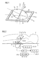
- the figure 1 has a device for holding at least one ultrasound probe suitable for viewing a limited area of a mobile and deformable subject.
- the probe and the subject are here not shown for the sake of clarity, but will be at the figure 2 .
- Said device comprises a mobile support (Se) in and with respect to an opening (St), as here a frame hollowed out in a plane (table, bed or support support) against which a superficial part of the subject is supported, said mobile support now solidarily at least a transmitting / receiving portion of the probe so as to make it freely movable by various mechanical thrusts exerted by variable pressures from the surface of the subject towards the opening.
- the probe can be held in the mobile support by clamping means A1, A2, A3, A4, the mobile support being itself mainly driven by a free rotation system relative to the frame opening comparably rotational means a marine compass that adapts to turn towards a horizontal course while compensating a vertical cottage to the ship.
- the spatial reference X T , Y T , Z T of the open-frame S T being known in an absolute manner, the initial position and the free and instantaneous posterior rotation of the probe can thus be deduced from the continuous measurement of the position d axes X E , Y E , Z E of the orthonormal reference frame of the probe or of the mobile support in the reference frame X T , Y T , Z T of the open-frame S T.
- This measurement can be performed by various metrological means usually electronic or optoelectronic today.
- the probe then delivering the coordinates of the limited area (localized tumor), it follows that the position of the tumor is immediately obtained in the reference frame X T , Y T , Z T of the opening frame S T and therefore in all another referential attached to it as the spatial reference of a radiotherapy annex installation and therefore by extending the target of its radiation beam towards the target tumor.
- the figure 2 presents for this purpose a diagram of possible use of the device according to the invention for controlling CTRL a positioning of ancillary equipment such as a radiation beam POS_BEAM of a radio-therapeutic installation.
- a patient P as a mobile and deformable subject is lying on a table T provided with the frame opening S T. It is important that the ultrasound probe E held in the frame aperture is offset from the beam path of a radiotherapy annex facility so as not to be damaged if the ultrasound probe is operating at the same time as the radiotherapy beam. .
- This is possible by placing the aperture-frame on a part of the table not targeted by the beam and tilting the probe initially relative to the vertical of the table.
- the probe on a plane other than that of the table, for example on a side wall while ensuring the support of the probe against a patient's surface conducive to guide the ultrasound to the area to be visualized including the tumor.
- the invention provides that at least one acoustic gel film G is disposed between the probe E and the surface contact portion between the patient and said probe to evacuate an air gap on an ultrasound channel between the probe. and the superficial part.
- the emitter / receiver part of the probe is supplied with a flow of acoustic gel G coming from a dispensing reservoir of said gel allowing a direct channeling of the ultrasound between the probe and the superficial part, said channel being thus made free of air gap.
- the transmitting / receiving part of the probe may be covered with an acoustic gel enclosure G of variable geometry providing support for the superficial portion and allowing a direct channeling of the ultrasound between the probe and the surface part. , said pipe thus being made free of air gap.
- at least one surface of the opening may comprise an acoustic gel enclosure G with variable geometry ensuring the support of the superficial portion and allowing a direct channeling of the ultrasound between the probe and the superficial portion, said duct being made free of air gap.
- the enclosure G may thus be an elastomer shape with variable geometry and having an acoustic impedance that minimizes acoustic losses between an ultrasound input / output of the probe and the surface portion, ideally by an impedance value approximated to that of the superficial part.
- the device according to the invention provides that, by driving the mobile support S E , the opening is positionable on at least one dimension of the plane. This allows a greater flexibility of positioning the probe in front of the zone to visualize and locate. Finally, the mobile support SE is tiltable (here freely) around a normal to the support plane T, to freely follow any patient support movements.
- the mobile support SE comprises first determination and calculation means CALC1 of its position X E , Y E , Z E (or that of the probe) in terms of translation and orientation in a known three-dimensional reference frame linked to the plane T.
- X C , Y C , Z C position of the visualized area C is delivered by measuring the probe or at least one associated spatial location module DET_C and can therefore using a calculating means CALC2, similar to the first computation means CALC1, also be determined in the known three-dimensional reference frame linked to the plane T.
- POS_BEAM positioning appendix such as that for spatially controlling CTRL the target of a radiotherapy radiation beam.
- the device according to the invention as a means of locating the limited zone in-vivo, for which the plane is a table on which, as subject, a living being is elongated and the limited area is a set of in-vivo cells to be spatially located by means of spatial coordinates instantly delivered by the ultrasound probe and means for calculating the instantaneous position of said probe relative to a reference mark three-dimensional linked to the plane.
- This use of the device according to the invention can provide that the probe is coupled to a control unit capable of visualization and / or dynamic spatial tracing of all the cells in-vivo, said unit being driven by an operator or a recognition algorithm. This promotes search and tracing of the desired area and its limits.
- Said control unit may also be coupled to an additional mechanism for controlling the positioning of the probe on a main orientation axis, around which the probe is placed in free orientation, said mechanism being controlled by the operator or the operator. recognition algorithm.
- This forced steering mechanism can be used to initially position the probe or to correct a position of the probe during a diagnosis or an adjunctive therapy to improve the vision of the cells.
- the use of the device according to the invention finally provides a safe and accurate servocontrol function of any apparatus attached to the device in order to guide it spatially and dynamically, in that the control unit is connected to a control unit positioning POS_BEAM, CTRL of a radiotherapy facility for example whose target is positionable on the in-vivo limited area towards which the main field of view of the ultrasound probe is maintained directed.
Landscapes
- Health & Medical Sciences (AREA)
- Life Sciences & Earth Sciences (AREA)
- Engineering & Computer Science (AREA)
- Biomedical Technology (AREA)
- Public Health (AREA)
- Surgery (AREA)
- Veterinary Medicine (AREA)
- Nuclear Medicine, Radiotherapy & Molecular Imaging (AREA)
- General Health & Medical Sciences (AREA)
- Pathology (AREA)
- Animal Behavior & Ethology (AREA)
- Heart & Thoracic Surgery (AREA)
- Molecular Biology (AREA)
- Medical Informatics (AREA)
- Physics & Mathematics (AREA)
- Radiology & Medical Imaging (AREA)
- Biophysics (AREA)
- Acoustics & Sound (AREA)
- Oral & Maxillofacial Surgery (AREA)
- Radiation-Therapy Devices (AREA)
- Ultra Sonic Daignosis Equipment (AREA)
Abstract
La présente invention décrit un dispositif de maintien d'au moins une sonde (E) à ultrason adaptée à la visualisation d'une zone limitée d'un sujet mobile et déformable (P), comprenant un support mobile (S E ) dans et par rapport à une ouverture (S T ) d'un plan (T) contre lequel une partie superficielle du sujet est appuyée, le dit support mobile maintenant solidairement au moins une partie émettrice/réceptrice de la sonde de façon à la rendre librement mobile par diverses poussées mécaniques exercées par des pressions variables provenant de la partie superficielle en direction de l'ouverture.
Description
- La présente invention concerne un dispositif de maintien d'au moins une sonde à ultrason selon le préambule de la revendication 1, ainsi que des aspects liés à son utilisation.
- Actuellement, un objectif majeur réside dans la visualisation de parties internes telles qu'in-vivo chez un sujet de type humain ou animal ou un mannequin dit aussi « fantôme ». En particulier, cet objectif est crucial dès lors qu'une intervention telle qu'une irradiation locale radiothérapeutique ou technologiquement équivalente en dépend afin de pouvoir localement irradier une zone limitée incluant des cellules à détruire tout en préservant de l'irradiation de tissus et cellules saines avoisinés aux cellules malsaines.
- Actuellement par exemple, lors d'une séance de radiothérapie sur des cellules cancéreuses telle qu'une tumeur ou un carcinome, un dispositif annexe à l'installation de radiothérapie permet de prendre des prises de vue de type radiographique afin de visualiser et localiser ladite tumeur in-vivo dans le référentiel de l'installation de radiothérapie, ceci aux fins de contrôler que le faisceau irradiant concentre bien son énergie sur la tumeur. Ce procédé à base d'irradiation nuisible (rayons X) n'est toutefois pas sans danger pour un patient déjà affaibli par un cancer et ne permet pas une visualisation ainsi qu'une localisation d'une cible à intervalles fréquents et donc a fortiori en temps réel lors de séances d'irradiation. De tels procédés sont aussi volumineux, coûteux et nécessitent de multiples interventions humaines pour leur positionnement, leur fonctionnement et leur maintenance. Un but de la présente invention est ainsi de pouvoir localiser un volume de cellules in-vivo, telles que des cellules cancéreuses, de façon la plus continue possible, en particulier à intervalles fréquents durant une séance d'irradiation desdites cellules.
- Un autre but de l'invention est aussi de pouvoir localiser un volume de cellules in-vivo, telles que des cellules cancéreuses, de façon la plus exacte possible, afin en particulier qu'une irradiation des dites cellules reste dynamiquement centrée sur le volume tout en épargnant des tissus sains périphériques. Ceci est d'autant plus important car il est inévitable qu'un patient (appuyé ou allongé sur une table comme surface de référence) n'est jamais immobile, et ses organes internes sont aussi mobiles, comme basiquement par exemple lors de ses cycles de respiration.
- Enfin, un problème alternatif de l'invention concerne le fait que la visualisation et la localisation d'une tumeur par exemple doit être effectuée en préservant la santé mais aussi le confort et la quiétude du patient afin de lui éviter tout stress complémentaire à un diagnostic voire une thérapie plus lourde et astreignante. Ainsi, toute irradiation invasive ou du moins nuisible, en supplément à celle liée à une possible radiothérapie ou une thérapie similaire, ainsi que l'usage de méthodes de maintien du patient, de marquage ou autre contrainte infligée au patient doit être minimisé, et idéalement éliminé.
- L'invention propose ainsi un dispositif approprié à résoudre cet ensemble de problèmes et décrit au travers de la revendication 1.
- A cet effet, l'invention prévoit un dispositif de maintien d'au moins une sonde à ultrason adaptée à la visualisation d'une zone limitée d'un sujet mobile et déformable tel qu'un patient. Le dispositif comprend un support mobile dans et par rapport à une ouverture d'un plan (table, lit muni d'un évidement en surface) contre lequel une partie superficielle du sujet est appuyée, le dit support mobile maintenant solidairement au moins une partie émettrice/réceptrice de la sonde de façon à la rendre librement mobile par diverses poussées mécaniques exercées par des pressions variables provenant de la partie superficielle en direction de l'ouverture.
- De part l'intégration avantageuse d'une sonde à ultrasons, il est ainsi possible de visualiser et localiser la zone limitée (volume de cellules tumorales par exemple) de façon continue et en temps réel, même chez un patient lourdement malade et affaibli, car les ultrasons n'ont pas d'effets nocifs et affaiblissants connus. Si le patient bouge par rapport à une table où il est allongé, le support mobile initialement disposé pour permettre d'inclure la zone visée et son voisinage dans son champ de vision (eux-mêmes en possible mouvement, par exemple par de simples raisons respiratoire, de flux sanguin ou d'autres aspects dynamiques in-vivo) assure un déplacement naturel de la sonde afin de toujours cadrer la zone visée dans son champ de vision. Cette unique prédisposition de la sonde peut-être réglée en début d'une phase de visualisation grâce à un opérateur, afin d'assurer une visualisation et localisation sans faille a posteriori.
- Les sondes à ultrasons actuelles permettent une vision bi- ou tridimensionnelle et donc, une fois que la zone limitée (tumeur) est localisée, il est possible de recalculer sa position par la simple connaissance du déplacement naturel de la sonde dans son support mobile par rapport au plan d'appui du patient (fixe ou du moins spatialement connu dans le référentiel de l'installation annexe de diagnostic/thérapie). Ladite localisation est donc fort exacte spatialement et absolument dynamique temporellement.
- Un ensemble de sous-revendications présente également des avantages de l'invention.
- Des exemples de réalisation et d'application sont fournis à l'aide de figures décrites :
- Figure 1
- dispositif de maintien d'au moins une sonde à ultrason selon l'invention,
- Figure 2
- schéma d'utilisation du dispositif selon l'invention pour contrôler un positionnement d'appareillage annexe.
- La
figure 1 présente un dispositif de maintien d'au moins une sonde à ultrason adaptée à la visualisation d'une zone limitée d'un sujet mobile et déformable. La sonde et le sujet sont ici non représentés pour des raisons de clarté, mais le seront à lafigure 2 .
Ledit dispositif comprend un support mobile (Se) dans et par rapport à une ouverture (St), comme ici un cadre évidé dans un plan (table, lit ou support d'appui) contre lequel une partie superficielle du sujet est appuyée, le dit support mobile maintenant solidairement au moins une partie émettrice/réceptrice de la sonde de façon à la rendre librement mobile par diverses poussées mécaniques exercées par des pressions variables provenant de la partie superficielle du sujet en direction de l'ouverture. - La sonde peut être maintenue dans le support mobile par des moyens de serrage A1, A2, A3, A4, le support mobile étant lui-même principalement mu par un système de rotation libre par rapport à l'ouverture-cadre comparablement à moyen de rotation d'un compas marin s'adaptant à tourner vers un cap horizontal tout en compensant une gite vertical au navire. Le référentiel spatial XT, YT, ZT de l'ouverture-cadre ST étant connue de façon absolue, la position initiale et la rotation postérieure libre et instantanée de la sonde peut ainsi être déduite de la mesure en continue de la position d'axes XE, YE, ZE du référentiel orthonormé de la sonde ou du support mobile dans le référentiel XT, YT, ZT de l'ouverture-cadre ST. Cette mesure peut être exécutée par divers moyens métrologique usuellement électroniques ou opto-électroniques de nos jours. La sonde délivrant ensuite les coordonnées de la zone limitée (tumeur localisée), il en découle que la position de la tumeur est immédiatement obtenue dans le référentiel XT, YT, ZT de l'ouverture-cadre ST et donc dans tout autre référentiel s'y rattachant comme le référentiel spatial d'une installation annexe de radiothérapie et donc par extension de la cible de son faisceau de radiation vers la tumeur visée.
- La
figure 2 présente à cet effet un schéma d'utilisation possible du dispositif selon l'invention pour contrôler CTRL un positionnement d'appareillage annexe tel qu'un faisceau de radiation POS_BEAM d'une installation radio-thérapeutique. Un patient P en tant que sujet mobile et déformable est couché sur une table T muni de l'ouverture-cadre ST. Il est important que la sonde à ultrasons E maintenue dans l'ouverture-cadre soit décalée du chemin du faisceau d'une installation annexe de radiothérapie afin de ne pas être endommagée si la sonde à ultrasons fonctionne en même temps que le faisceau radio-thérapeutique. Ceci est possible en plaçant l'ouverture-cadre sur une partie de la table non ciblée par le faisceau et en inclinant la sonde initialement par rapport à la verticale de la table. Il est aussi possible de disposer la sonde sur un autre plan que celui de la table, par exemple sur une paroi latérale tout en assurant l'appui de la sonde contre une surface du patient propice à guider les ultrasons vers la zone à visualiser comprenant la tumeur. - L'invention prévoit qu'au moins un film de gel acoustique G est disposé entre la sonde E et la partie de contact superficiel entre le patient et ladite sonde afin d'évacuer un interstice d'air sur un canal d'ultrasons entre la sonde et la partie superficielle.
- Alternativement, la partie émettrice/réceptrice de la sonde est alimentée par un flux de gel acoustique G provenant d'un réservoir de distribution dudit gel permettant une canalisation directe des ultrasons entre la sonde et la partie superficielle, ladite canalisation étant ainsi rendue libre d'interstice d'air.
- Egalement, il est aussi possible que la partie émettrice/réceptrice de la sonde soit recouverte d'une enceinte de gel acoustique G à géométrie variable assurant l'appui de la partie superficielle et permettant une canalisation directe des ultrasons entre la sonde et la partie superficielle, ladite canalisation étant ainsi rendue libre d'interstice d'air. Alternativement, au moins une surface de l'ouverture peut comprendre une enceinte de gel acoustique G à géométrie variable assurant l'appui de la partie superficielle et permettant une canalisation directe des ultrasons entre la sonde et la partie superficielle, ladite canalisation étant rendue libre d'interstice d'air. L'enceinte G peut ainsi être une forme élastomère à géométrie variable et ayant une impédance acoustique minimisant des pertes acoustique entre une entrée/sortie d'ultrasons de la sonde et de la partie superficielle, idéalement par une valeur d'impédance avoisinée à celle de la partie superficielle.
- Le dispositif selon l'invention prévoit que, par entrainement du support mobile SE, l'ouverture est positionnable sur au moins une dimension du plan. Ceci permet une plus grande flexibilité de positionnement de la sonde en face de la zone à visualiser et localiser. Enfin, le support mobile SE est inclinable (ici librement) autour d'une normale au plan d'appui T, afin de suivre librement des mouvements quelconques d'appui du patient.
- Afin de pouvoir calculer ces mouvements du patient ainsi que le déplacement potentiel et donc la position XC, YC, ZC de la zone visualisée C à localiser (tumeur) pendant une acquisition d'image SCAN de la sonde à ultrasons E, le support mobile SE comprend des premiers moyens de détermination et de calcul CALC1 de sa position XE, YE, ZE (ou celle de la sonde) en termes de translation et d'orientation dans un référentiel tridimensionnel connu lié au plan T. La position XC, YC, ZC de la zone visualisée C est délivrée par la mesure de la sonde ou du moins un module de localisation spatiale associé DET_C et peut donc à l'aide d'un moyen de calcul CALC2, similaire aux premiers moyens de calcul CALC1, être aussi déterminée dans le référentiel tridimensionnel connu lié au plan T.
- Après connaissance de la position de XC, YC, ZC de la zone visualisée C à localiser (tumeur), celle-ci peut être transmise sous des coordonnées adaptées XT, YT, ZT dans un référentiel propre à un appareillage annexe de positionnement POS_BEAM tel que celui pour contrôler CTRL spatialement la cible d'un faisceau d'irradiation radio-thérapeutique.
- Il est donc avantageux de proposer une utilisation du dispositif selon l'invention comme moyen de localisation de la zone limitée in-vivo, pour laquelle le plan est une table sur laquelle, en tant que sujet, un être vivant est allongé et la zone limitée est un ensemble de cellules in-vivo à localiser spatialement au moyen de coordonnées spatiales instantanément délivrées par la sonde à ultrasons et de moyen de calcul de la position instantanée de ladite sonde par rapport à un repère tridimensionnel lié au plan.
- Cette utilisation du dispositif selon l'invention peut prévoir que la sonde est couplée à une unité de contrôle apte à une visualisation ou/et un traçage spatial dynamique de l'ensemble des cellules in-vivo, la dite unité étant pilotée par un opérateur ou un algorithme de reconnaissance. Ceci favorise la recherche et le traçage de la zone voulue et ses limites.
- Ladite unité de contrôle peut être également couplée à un mécanisme additionnel de commande forcée de positionnement de la sonde sur un axe d'orientation principal, autour duquel la sonde est mise en libre orientation, le dit mécanisme étant piloté par l'opérateur ou l'algorithme de reconnaissance. Ce mécanisme de pilotage forcé peut servir à positionner initialement la sonde ou à corriger une position de la sonde lors d'un diagnostic ou une thérapie annexe afin d'améliorer la vision des cellules.
- Enfin, l'utilisation du dispositif selon l'invention prévoit enfin une fonction d'asservissement sécuritaire et précis de tout appareillage annexe au dispositif afin de le guider spatialement et dynamiquement, en ce que l'unité de contrôle est reliée à une unité de commande de positionnement POS_BEAM, CTRL d'une installation par exemple radio-thérapeutique dont la cible est positionnable sur la zone limitée in-vivo vers laquelle le champ principal de vision de la sonde à ultrasons est maintenue dirigée.
Claims (13)
- Dispositif de maintien d'au moins une sonde (E) à ultrason adaptée à la visualisation d'une zone limitée d'un sujet mobile et déformable (P),
comprenant un support mobile (SE) dans et par rapport à une ouverture (ST) d'un plan (T) contre lequel une partie superficielle du sujet est appuyée, le dit support mobile maintenant solidairement au moins une partie émettrice/réceptrice de la sonde de façon à la rendre librement mobile par diverses poussées mécaniques exercées par des pressions variables provenant de la partie superficielle en direction de l'ouverture. - Dispositif selon revendication 1, pour lequel au moins un film de gel acoustique est disposé entre la sonde et la partie superficielle afin d'évacuer un interstice d'air sur un canal d'ultrasons entre la sonde et la partie superficielle.
- Dispositif selon revendication 1, pour lequel la partie émettrice/réceptrice de la sonde est alimentée par un flux de gel acoustique (G) provenant d'un réservoir de distribution dudit gel permettant une canalisation directe des ultrasons entre la sonde et la partie superficielle, ladite canalisation étant rendue libre d'interstice d'air.
- Dispositif selon revendication 1, pour lequel la partie émettrice/réceptrice de la sonde est recouverte d'une enceinte de gel acoustique (G) à géométrie variable assurant l'appui de la partie superficielle et permettant une canalisation directe des ultrasons entre la sonde et la partie superficielle, ladite canalisation étant rendue libre d'interstice d'air.
- Dispositif selon revendication 1, pour lequel au moins une surface de l'ouverture comprend une enceinte de gel acoustique (G) à géométrie variable assurant l'appui de la partie superficielle et permettant une canalisation directe des ultrasons entre la sonde et la partie superficielle, ladite canalisation étant rendue libre d'interstice d'air.
- Dispositif selon une des revendications 4 ou 5, pour lequel l'enceinte est une forme élastomère à géométrie variable et ayant une impédance acoustique minimisant des pertes acoustique entre une entrée/sortie d'ultrasons de la sonde et de la partie superficielle, idéalement par une valeur d'impédance avoisinée à celle de la partie superficielle.
- Dispositif selon une des revendications précédentes, pour lequel par entrainement du support mobile, l'ouverture est positionnable sur au moins une dimension du plan.
- Dispositif selon une des revendications précédentes, pour lequel le support mobile (SE) est inclinable autour d'une normale au plan.
- Dispositif selon une des revendications précédentes, pour lequel le support mobile (SE) comprend des moyens de détermination de sa position en translation et orientation dans un référentiel tridimensionnel lié au plan.
- Utilisation du dispositif selon une des revendications précédentes comme moyen de localisation de la zone limitée in-vivo, pour laquelle le plan est une table sur laquelle, en tant que sujet, un être vivant est allongé et la zone limitée est un ensemble de cellules in-vivo à localiser spatialement au moyen de coordonnées spatiales instantanément délivrées par la sonde et de moyen de calcul de la position instantanée de la sonde par rapport à un repère tridimensionnel lié au plan.
- Utilisation selon revendication 10, pour laquelle la sonde est couplée à une unité de contrôle apte à une visualisation ou/et un traçage spatial de l'ensemble des cellules in-vivo, la dite unité étant pilotée par un opérateur ou un algorithme de reconnaissance.
- Utilisation selon revendication 11, pour laquelle l'unité de contrôle est couplée à un mécanisme additionnel de commande forcée de positionnement de la sonde sur un axe d'orientation principal, autour duquel la sonde est mise en libre orientation, le dit mécanisme étant piloté par l'opérateur ou l'algorithme de reconnaissance.
- Utilisation selon revendication 11 ou 12, pour laquelle l'unité de contrôle est reliée à une unité de commande de positionnement d'une installation radiothérapeutique dont la cible est positionnable sur la zone limitée in-vivo.
Priority Applications (2)
| Application Number | Priority Date | Filing Date | Title |
|---|---|---|---|
| EP09166267A EP2277450A1 (fr) | 2009-07-23 | 2009-07-23 | Dispositif de maintien d'au moins une sonde à ultrason |
| PCT/EP2010/059893 WO2011009741A1 (fr) | 2009-07-23 | 2010-07-09 | Dispositif de maintien d'au moins une sonde à ultrason |
Applications Claiming Priority (1)
| Application Number | Priority Date | Filing Date | Title |
|---|---|---|---|
| EP09166267A EP2277450A1 (fr) | 2009-07-23 | 2009-07-23 | Dispositif de maintien d'au moins une sonde à ultrason |
Publications (1)
| Publication Number | Publication Date |
|---|---|
| EP2277450A1 true EP2277450A1 (fr) | 2011-01-26 |
Family
ID=41171254
Family Applications (1)
| Application Number | Title | Priority Date | Filing Date |
|---|---|---|---|
| EP09166267A Withdrawn EP2277450A1 (fr) | 2009-07-23 | 2009-07-23 | Dispositif de maintien d'au moins une sonde à ultrason |
Country Status (2)
| Country | Link |
|---|---|
| EP (1) | EP2277450A1 (fr) |
| WO (1) | WO2011009741A1 (fr) |
Citations (5)
| Publication number | Priority date | Publication date | Assignee | Title |
|---|---|---|---|---|
| GB369662A (en) * | 1930-12-24 | 1932-03-24 | Ernst Pohl | Improvements in and relating to the radioscopic and radiographic reproduction of a section through a body |
| DE8515656U1 (de) * | 1985-05-28 | 1986-11-13 | Siemens AG, 1000 Berlin und 8000 München | Einrichtung zum berührungslosen Zertrümmern von Konkrementen |
| EP0607490A1 (fr) * | 1993-01-21 | 1994-07-27 | Aloka Co., Ltd. | Appareil de sonde à ultra-sons |
| EP1286172A2 (fr) * | 2001-08-14 | 2003-02-26 | Esaote S.p.A. | Appareil d'imagerie par résonance magnétique et ultrasons |
| JP2007111386A (ja) * | 2005-10-21 | 2007-05-10 | Tokyo Univ Of Agriculture & Technology | 医療用ベッドおよび診断/治療システム |
-
2009
- 2009-07-23 EP EP09166267A patent/EP2277450A1/fr not_active Withdrawn
-
2010
- 2010-07-09 WO PCT/EP2010/059893 patent/WO2011009741A1/fr not_active Ceased
Patent Citations (5)
| Publication number | Priority date | Publication date | Assignee | Title |
|---|---|---|---|---|
| GB369662A (en) * | 1930-12-24 | 1932-03-24 | Ernst Pohl | Improvements in and relating to the radioscopic and radiographic reproduction of a section through a body |
| DE8515656U1 (de) * | 1985-05-28 | 1986-11-13 | Siemens AG, 1000 Berlin und 8000 München | Einrichtung zum berührungslosen Zertrümmern von Konkrementen |
| EP0607490A1 (fr) * | 1993-01-21 | 1994-07-27 | Aloka Co., Ltd. | Appareil de sonde à ultra-sons |
| EP1286172A2 (fr) * | 2001-08-14 | 2003-02-26 | Esaote S.p.A. | Appareil d'imagerie par résonance magnétique et ultrasons |
| JP2007111386A (ja) * | 2005-10-21 | 2007-05-10 | Tokyo Univ Of Agriculture & Technology | 医療用ベッドおよび診断/治療システム |
Non-Patent Citations (1)
| Title |
|---|
| DATABASE WPI Week 200754, Derwent World Patents Index; AN 2007-548854, XP002552345 * |
Also Published As
| Publication number | Publication date |
|---|---|
| WO2011009741A1 (fr) | 2011-01-27 |
Similar Documents
| Publication | Publication Date | Title |
|---|---|---|
| JP4338976B2 (ja) | アブレーティブレーザーエネルギーを供給し、破壊された腫瘍の塊のボリュームを決定する装置及びその方法 | |
| EP3706656B1 (fr) | Dispositif robotisé pour une intervention médicale mini-invasive sur des tissus mous | |
| US10293189B2 (en) | Ultrasonic apparatus, a therapeutic system and a method of increasing a workflow | |
| EP2340781B1 (fr) | Procédé et appareil de localisation et de visualisation d'une cible par rapport à un point focal d'un système de traitement | |
| CN109310363B (zh) | 一种术中光声导航设备及方法 | |
| US10667869B2 (en) | Guidance system for needle procedures | |
| US6041249A (en) | Device for making a guide path for an instrument on a patient | |
| FI120668B (fi) | Röntgenkuvauslaite ja röntgenkuvauskohteen paikannusjärjestely | |
| US9033886B2 (en) | Ultrasound treatment device | |
| US20060285641A1 (en) | System, tracker, and program product to facilitate and verify proper target alignment for radiation delivery, and related methods | |
| JP2018531766A (ja) | 体内の標的構造物に超音波誘導を与えるためのシステム及び方法 | |
| WO2020112677A3 (fr) | Procédés de balayage et système de tomographie optimisés utilisant des données de région d'intérêt | |
| US20080103388A1 (en) | Medical examination and/or treatment apparatus | |
| DE60111385D1 (de) | Gerät zur lokalisation einer läsion oder eines organs | |
| KR20060113930A (ko) | 지방 조직의 파괴를 위한 시스템 및 장치 | |
| WO2007017771A3 (fr) | Systeme de navigation de catheter | |
| US20160332006A1 (en) | Motion Mechanisms for Ultrasound Transducer Modules | |
| CN101247850A (zh) | 用于分析放射治疗设备几何的系统、软件和相关方法 | |
| JP2008188426A (ja) | 無較正の幾何学的構成における三次元撮像の方法及びシステム | |
| JP2008545486A (ja) | 生体の器官を対象とした画像形成・治療ヘッドと製造方法 | |
| EP3952739A1 (fr) | Dispositif et procede de synchronisation pour la determination d'un instant du cycle respiratoire d'un patient, et ensemble comportant un robot medical | |
| US20190209119A1 (en) | System and Method for Angular Alignment of a Probe at a Target Location | |
| EP2277449A1 (fr) | Dispositif de positionnement d'une sonde à ultrasons | |
| FR2756169A1 (fr) | Dispositif d'asservissement de la position du foyer pour un appareil de therapie | |
| WO2011009741A1 (fr) | Dispositif de maintien d'au moins une sonde à ultrason |
Legal Events
| Date | Code | Title | Description |
|---|---|---|---|
| PUAI | Public reference made under article 153(3) epc to a published international application that has entered the european phase |
Free format text: ORIGINAL CODE: 0009012 |
|
| AK | Designated contracting states |
Kind code of ref document: A1 Designated state(s): AT BE BG CH CY CZ DE DK EE ES FI FR GB GR HR HU IE IS IT LI LT LU LV MC MK MT NL NO PL PT RO SE SI SK SM TR |
|
| AX | Request for extension of the european patent |
Extension state: AL BA RS |
|
| STAA | Information on the status of an ep patent application or granted ep patent |
Free format text: STATUS: THE APPLICATION IS DEEMED TO BE WITHDRAWN |
|
| 18D | Application deemed to be withdrawn |
Effective date: 20110727 |