EP2277373B1 - Fluid application system - Google Patents
Fluid application system Download PDFInfo
- Publication number
- EP2277373B1 EP2277373B1 EP10174459.7A EP10174459A EP2277373B1 EP 2277373 B1 EP2277373 B1 EP 2277373B1 EP 10174459 A EP10174459 A EP 10174459A EP 2277373 B1 EP2277373 B1 EP 2277373B1
- Authority
- EP
- European Patent Office
- Prior art keywords
- milking
- fluid
- detachment
- teat cup
- teat
- Prior art date
- Legal status (The legal status is an assumption and is not a legal conclusion. Google has not performed a legal analysis and makes no representation as to the accuracy of the status listed.)
- Not-in-force
Links
Images


Classifications
-
- A—HUMAN NECESSITIES
- A01—AGRICULTURE; FORESTRY; ANIMAL HUSBANDRY; HUNTING; TRAPPING; FISHING
- A01J—MANUFACTURE OF DAIRY PRODUCTS
- A01J7/00—Accessories for milking machines or devices
- A01J7/04—Accessories for milking machines or devices for treatment of udders or teats, e.g. for cleaning
Definitions
- the present invention is related generally to dairy farming.
- disinfectant and/or skin conditioner can prevent the teats of the animals from becoming infected or dry, or otherwise affected by environment, e.g. dry, chapped, frost-bitten, etc.
- US 6,935,270 B2 discloses a milking and applicator teat cup configured to receive an animal teat within a liner located in a shell. At the openings of the liner and shell where the teat is received, there is an applicator configured to dispense disinfectant, conditioning, and/or cleaning solution to the animal teat. The applicator is designed to discharge the solution horizontally across the openings of the liner and the shell.
- a teat cup can be integrated into a milking system having a valve manifold coupled to a number of teat cups and controlling flow of milk from the number of teat cups and flow of fluid to the applicators, and a controller including logic configured to provide control signals to the valve manifold. The controller signals the valve manifold to pre-charge a hose or line delivering fluid to the applicator and signals the valve manifold for the end of milking and begin delivery of the fluid from the applicator.
- DE 10 2004 044916 A1 discloses a method for bringing a fluid into contact with a teat of an animal, in particular of a cow, and also to a teat cup that is suitable for bringing a fluid into contact with a teat of an animal.
- the invention refers to a fluid application system according to claims 1 to 5.
- the solution should be prevented from being discharged in case an abnormal teat cup take off is performed and in which case the teat cup should be re-attached to re-establish milking since such milk may otherwise be contaminated by the discharged solution.
- a fluid application system comprising a fluid delivery arrangement provided with a plurality of applicators, wherein each of the applicators is arranged in connection with a respective teat cup of milking equipment and is provided for applying the fluid to a teat of the animal, to which the respective teat cup is attached during the milking of the animal, in connection with a detachment of the teat cup from the teat.
- the fluid application system may further comprise a control arrangement, which is arranged for determining, for a detachment of a teat cup from a teat, whether that detachment is a normal detachment or an abnormal detachment.
- the control arrangement finally controls, for the detachment of the teat cup of from the teat, the applicator arranged in connection with that teat cup to apply the fluid provided that the detachment is a normal detachment and to not apply the fluid provided that the detachment is an abnormal detachment.
- control arrangement may be connected to a number of sensors and apparatuses, which provide the control arrangement with data that can be used in the decision.
- Such sensors and apparatuses may include, but are not limited to, a milk flow meter for repeatedly measuring a milk flow rate from the animal, a time measurement device for measuring a time lapsed from start of the milking of the animal, a milk yield measurement device for repeatedly measuring a milk yield as produced by the animal during the milking, and a device for detecting teat cup fall offs or slips during the milking of the animal, a device for detecting the movement of the animal during the milking, and a vacuum sensor for repeatedly measuring a vacuum level in the milking equipment during the milking.
- animals are cows.
- the invention is not limited to cows, but is applicable to any animals having the capability of producing milk, such as sheep, goats, buffaloes, horses, etc.
- the milking system shown in Fig. 1 is oriented in position for milking a cow 12 with teat cups 13 attached to the teats of the udder. It includes a side outlet milking claw for illustration purposes.
- the milk is directed from the liners of the teat cups 13 through flexible milk tubes or short milk hoses or tubes 14 through inlets 16 to a milking bowl 18 of a claw 10.
- the claw 10 is supported by a teat cup cluster support 20 that is connected to a hanger 21 of the milking claw.
- the milk exits from the bowl 18 of the claw through an outlet tube 23 to which a milk hose 24 is coupled.
- the milk hose 24 is connected to a milking pipe 25 that is under a milking vacuum so as to draw the milk from the milk hose 24 into the milk pipe 25.
- a milk flow sensor 27 is shown in connection with the milk hose 24 to sense a milk flow rate and provide an indication when the cow has been milked completely so that the teat cups 13 may be automatically detached from the cow.
- the milking system comprises a fluid application system for automatically applying a fluid such as a disinfectant and/or conditioning solution to the teats of the cow 12 subsequent to the milking of the cow 12. Such procedure is also referred to as a post-dip.
- the fluid application system comprises a plurality of applicators 17, each being arranged in a respective teat cup 13 near the opening of the teat cup 13 that receives the cow teat.
- the applicator 17 dispenses disinfectant and/or conditioning solution onto the teats of the cow after milking as the teat cup 13 descends from the teat.
- the solution dispensed by the applicator 17 is received from a fluid hose 31 via a solution delivery line 33.
- the solution delivery line 33 is preferably connected to a large container 35 of conditioning and/or disinfectant solution.
- the fluid application system further comprises a control arrangement 30 provided for determining, for each detachment of a teat cup 13 from a respective teat of the cow 12, whether that detachment is a normal detachment or an abnormal detachment.
- the control arrangement 30 is in the embodiment of Fig. 1 connected to the milk flow sensor 27 to receive repeatedly measured milk flow rate values during the milking of the cow. The control arrangement 30 may then determine whether a detachment is a normal detachment or an abnormal detachment depending on the repeatedly measured milk flow rate values.
- an abnormal detachment is defined as a detachment prior to the normal end of milking caused by an unforeseen event such as a teat cup fall off.
- an abnormal detachment is followed by a re-attachment of the teat cup to the teat for further milking of that teat.
- control arrangement 30 may be provided for determining that a detachment is an abnormal detachment provided that the repeatedly measured milk flow rate falls below a first threshold value during a first measured time period, that is, the repeatedly measured milk flow rate falls sufficiently fast, which is the case for a sudden abnormal teat cup detachment such as a teat cup fall off. At normal end of milking the repeatedly measured milk flow rate falls less steep.
- control arrangement 30 is provided, for each detachment, to control the flow of fluid to the applicators 17, in particular the applicator arranged in connection with that teat cup, to apply the fluid if the detachment is a normal detachment and to not apply the fluid if the detachment is an abnormal detachment.
- a teat cup should be re-attached to the teat of the cow subsequent to an abnormal teat cup detachment no fluid is dispensed in the teat cup 13 and thus there is no risk of contaminating the milk collected via the milk hose 24 and the milking pipe 25.
- control arrangement 30 is provided, for each detachment, to control the flow of fluid to the applicators 17 to apply the fluid to all teats of the cow in connection with take-off if the detachment is a normal detachment and to not apply the fluid to any of the teats if the detachment is an abnormal detachment.
- the decision whether application of fluid should be applied or not on a teat individual level may be made in milking system with separate milk collection equipment for each teat or udder quarter such as the DeLaval voluntary milking system VMS.
- control arrangement 30 may be connected to other sensor and apparatuses, which provide the control arrangement 30 with data that can be used in the decision as to whether a teat cup detachment is a normal detachment or an abnormal detachment.
- Fig. 2 shows a control arrangement 30 in accordance with an embodiment of the invention as connected to sensors and devices, which provide the control arrangement 30 with decision data.
- the control arrangement 30 may receive measurement values from a plurality of the sensors arranged in connection with the milking equipment and/or the cow. The received measurement values are input as parameters in a decision algorithm, which is run, and an abnormal detachment of the teat cup from the teat is detected depending on the result from the decision algorithm.
- the sensors and devices comprise except for the milk flow meter 27, a time measurement device or timer 42 provided for measuring a time elapsed from start of the milking of the cow. If the lapsed time is below a second threshold value, this could point towards that the teat cup detachment is an abnormal detachment, whereas if the lapsed time is above a third threshold value, this could points towards that the teat cup detachment is a normal detachment.
- the second and third threshold values could be identical, but to obtain more certain observations the third threshold is preferably higher than the second threshold value. If the lapsed time is between the second and third threshold values no establishment whether the teat cup detachment is a normal or abnormal detachment can be made. If this timer 42 is combined with other sensors and devices, an elapsed time between the second and third threshold values could indicate that the decision algorithm does not take the elapsed time into account.
- control arrangement 30 is connected to a milk yield measurement device 43 provided for repeatedly measuring a milk yield as produced by the cow during the milking. If measured milk yield is below a fourth threshold value, this could point towards that the teat cup detachment is an abnormal detachment, whereas if the measured milk yield is above a fifth threshold value, this could point towards that the teat cup detachment is a normal detachment.
- the fourth and fifth threshold values could be identical, but to obtain more certain observations the fifth threshold is preferably higher than the fourth threshold value. If the milk yield measurement device 43 is combined with other sensors and devices, a measured milk yield between the fourth and fifth threshold values could indicate that the decision algorithm does not take the milk yield into account.
- control arrangement 30 is connected to a device 44 provided for detecting teat cup fall off during the milking of the cow, wherein the control arrangement 30 is provided for determining whether the detachment is a normal detachment or an abnormal detachment depending on the detection of teat cup fall off.
- a sudden teat cup fall off could be an indication of an abnormal teat cup detachment in contrary to a normal detachment which is much slower.
- the device 44 may e.g. be an accelerometer based device.
- control arrangement 30 is connected to a device 45 for measuring the activity or movement of the cow during the milking thereof, and the control arrangement 30 is provided for determining whether the detachment is a normal detachment or an abnormal detachment depending on the detected activity or movement during the milking. A high activity or large or many movements could be an indication of an abnormal teat cup detachment.
- control arrangement 30 is connected to a device 46 for repeatedly measuring the vacuum level in the milking system during the milking of the cow and the control arrangement 30 is provided for determining whether the detachment is a normal detachment or an abnormal detachment depending on the repeatedly measure vacuum level in the milking system.
- a very fast vacuum drop could point towards an abnormal teat cup detachment, whereas a slower vacuum drop could point towards a normal teat cup detachment.
- threshold values for vacuum levels which can be used to determine normal/abnormal detachment.
- control arrangement 30 may determine whether a teat cup detachment is a normal detachment or an abnormal detachment based on results from some or all of the sensors and apparatuses as illustrated in Fig. 2 . Further, sensors and apparatuses to be used in the present invention may be readily contemplated by a person skilled in the art.
- devices for measuring air inlets into the milking equipment and devices for measuring milk slugs in the milking equipment are examples of further devices usable in the present invention. These devices may for instance be based on optical instruments.
- control arrangement 30 determines that an abnormal teat cup detachment has taken place, no fluid is dispensed through the applicators 17. The cluster is removed and the control arrangement 30 may then signal to the dairy farmer that an abnormal teat cup detachment has been made.
- the dairy farmer may continue the milking operation in a number of manners which include inter alia the following:
- control arrangement 30 can be provided, for each detachment of a teat cup from a teat of a selected cow, for controlling the applicators to not apply the fluid irrespective whether the detachment is a normal detachment or an abnormal detachment.
- the selected cow may be a cow that usually creates a problem, such as teat cup kick off, etc. or a cow that needs to be treated after milking.
- Such cow may be tagged in the control arrangement 30 to not be post-dipped automatically and when this cow has entered a specific stall the milking system management device will communicate to the control arrangement 30 that this cow is tagged as a "no post-dip" cow and then the control arrangement 30 turns off the applicator system automatically so that no fluid will be applied at teat cup detachment.
- This process of turning the applicator system off at the control device 30 may also be performed manually by the operator through a user interface provided for such.
- the fluid delivery arrangement contains two solenoid type valves, connected in series to provide a failsafe delivery arrangement in order to prevent applying of fluid if one of the two valves fails.
- the valves are spring loaded valves that default to the closed position and must be energized to open.
- the fluid delivery arrangement may contain separate lines for delivery of the fluid, water, and air to the teat cups.
- a valve manifold may contain four valves, one for the delivery of each of the fluid, water, and air and one safety valve that is connected in series with each of the other valves.
- This additional safety valve needs to be energized for the fluid or water or air to actually be supplied to the cluster. If, for instance, the fluid valve fails in an open position the fluid will ejected from the valve manifold and to a safe place where it will not contaminate the milk. The fluid will only be supplied to the cluster when both the fluid and the safety valve are open.
- control arrangement 30 could also be used in some specific applications, e.g. when group back flush is not suitable such as in rotary milking parlors, for the control of teat cup cleaning, such as a back flush procedure.
- Fig. 3a illustrates a milking system having, for each of a plurality of milking positions or stalls, milking equipment 51 for milking an animal, a milking stall controller 52 for controlling the milking of the animal by the milking equipment, a fluid application apparatus 53 as has been described above, and a stand-alone fluid application controller 54, which may be identical with the control arrangement 30 as has been described above.
- the milking stall controller 52 is arranged for determining whether a detachment of a teat cup is an abnormal or a normal teat cup detachment and this information is transferred to the stand-alone fluid application controller 54, which controls the fluid application.
- the stand-alone fluid application controller 54 is at standby, and the milking equipment 51 is operated under the control of the milking stall controller 52 as in a conventional milking system which lacks an automatic fluid application apparatus.
- the stand-alone fluid application controller 54 may take over the control of the milking equipment 51 in connection with the detachment of a teat cup, which includes vacuum control at end of milking (i.e. switching off the vacuum) and teat cup removal control.
- the application of the fluid has to be synchronized with teat cup detachment and therefore the milking stall controller 52 is by-passed, and the fluid application controller 54 controls both the milking equipment 51 and the fluid application apparatus 53.
- the stand-alone fluid application controller 54 (i) only takes over the control of the switching off of the vacuum, (ii) only takes over the control of the teat cup take-off, or (iii) does not take over any of the duties from the milking stall controller 52. In the latter case the two controllers are timed to work properly with one another.
- Such fluid application apparatus with a stand-alone fluid application controller is suitably implemented in existing milking systems lacking any kind of fluid application capabilities.
- Teat cup cleaning such as a back flush procedure may be performed under the control of either the milking stall controller or the fluid application controller or other stand-alone controller.
- Fig. 3b illustrates a milking system having, for each of a plurality of milking stalls, milking equipment 51 for milking an animal, a fluid application apparatus 53 as has been described above, and a combined milking stall and fluid application controller 60, which controls both the milking equipment 51 and the fluid application apparatus 53 at all instants.
- Such fluid application apparatus with a combined milking stall and fluid application controller 60 is suitably implemented in novel milking systems.
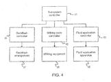
- a milking system is schematically illustrated, which comprises a subsystem controller 61, which may be connected to a herd management system (not illustrated) and is responsible for the overall control of the milking system.
- the subsystem controller 61 is operatively connected to three controllers, a milking stall controller 62, a fluid application controller 63, and a back flush controller 67.
- the milking stall controller 62 is provided for the control of milking equipment 65 of a milking position
- the fluid application controller 63 is provided for controlling a fluid application apparatus 66 of a milking position, e.g.
- the fluid application apparatus of the present invention the fluid application apparatus of US 6,935,270 B2 , or any other fluid application apparatus that applies a fluid to the teats of the cows within teat cups
- the back flush controller 67 is provided for controlling a back flush apparatus or other kind of cleaning apparatus for the cleaning of the teat cups at a milking position between each milking.
- the milking stall controller 62, the fluid application controller 63, and the back flush controller 67 operate under the control of the subsystem controller 61.
- the milking system may comprise only one subsystem controller 61, whereas the number of each of the other devices and apparatuses may correspond to the number of milking positions in the milking system.
- milking stall controller 62 and the fluid application controller 63 may be integrated into a single device.
- back flush controller 64 may also be integrated with the milking stall controller 62 and/or the fluid application controller 63.
- subsystem controller 61 may control each of the back flush apparatuses 67 directly and in such instance the back flush controllers 64 may be dispensed with.
- a problem with a system having both a fluid application apparatus and a teat cup cleaning apparatus such as the back flush apparatus 67 is that if the teat cup cleaning apparatus is disabled for some reason, the fluid application apparatus will apply a fluid to the teats of the cow in the teat cups subsequent to milking, and the fluid will not be removed before a next cow is to be milked. As a result the milk may be contaminated.
- the back flush controller is arranged to automatically enable the back flush apparatus, and/or if the back flush controller is arranged to disable the back flush apparatus, the fluid application controller is arranged to automatically disable the automatic fluid application apparatus.
- the teat cup cleaning apparatus is enabled if the fluid application apparatus is enabled, and as a result the teat cups will always be cleaned after the application of the fluid.
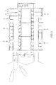
- the milking system is of a parallel stall type with two rows of twelve milking positions.
- the milking system comprises two entrance gate arrangements 70, one for each row, and six exit gate arrangements 71, one for each group of four adjacent milking positions.
- Each of the two entrance gate arrangements 70 comprises an identification device to identify the cows as they sequentially enter each of the rows of the milking system.
- a respective movable crowd gate may be provided at each of the rows of the milking system.
- the milking system comprises one subsystem controller, a back flush or other kind of teat cup cleaning apparatus, and for each milking stall milking equipment including a cluster and teat cups, a fluid application apparatus, a cluster detachment apparatus, and a controller for the milking equipment and the fluid application apparatus (not explicitly illustrated).
- the progress of the milking is monitored manually and as the milking is terminated the exit gate arrangements 71 are opened in response to a manual command by the dairy farmer.
- a problem with a prior art milking system of the above kind is that it is labor intensive and the time required for one milking cycle is too long. Particularly, the monitoring of the progress of the milking and the manual operation of the exit gate arrangements 71 are labor intensive. Further, the time elapsed between the end of the last cow in a group completing milking until the opening of the exit gates is too long.
- a milking cycle is performed as follows, starting with cows present at the milking positions:
- the above milking procedure is applicable to milking systems having a common exit gate for each row of milking stalls and to milking stalls having an exit gate of each single milking stall.
- the subsystem controller collects the all set signals from the milking stall controllers and for each all set signal the subsystem controller controls the exit gate of the corresponding milking stall to open and allow the cow at the milking stall to leave the milking system.
- each of the cows is allowed to leave the milking system when the cow has been post-dipped.
Landscapes
- Life Sciences & Earth Sciences (AREA)
- Animal Husbandry (AREA)
- Environmental Sciences (AREA)
- Cleaning In General (AREA)
- Dairy Products (AREA)
- Application Of Or Painting With Fluid Materials (AREA)
- Coating Apparatus (AREA)
- External Artificial Organs (AREA)
Description
- The present invention is related generally to dairy farming.
- Cleaning, disinfecting, and/or protecting the teats of the animals is an important part in dairy farming. The use of disinfectant and/or skin conditioner can prevent the teats of the animals from becoming infected or dry, or otherwise affected by environment, e.g. dry, chapped, frost-bitten, etc.
- It is considered important in conventional systems where skin conditioner and/or skin disinfectant is applied manually using a cup-dipping (submersion) application that it be applied within seconds of removal of the milking teat cup. The primary reason is that the teat orifice remains stretched and distended as a result of the pneumatic/mechanical action of milking. The application of fluid has better access to the convoluted tissue opening for germicidal or conditioning activity prior to the teat tissue regaining normal circulation under atmospheric conditions and subsequent involution of the teat orifice and streak canal. Additionally, the teat cistern's deteriorating residual vacuum can assist a droplet in coating the distal surfaces of the streak canal for more effective germicidal or conditioning activity.
-
US 6,935,270 B2 discloses a milking and applicator teat cup configured to receive an animal teat within a liner located in a shell. At the openings of the liner and shell where the teat is received, there is an applicator configured to dispense disinfectant, conditioning, and/or cleaning solution to the animal teat. The applicator is designed to discharge the solution horizontally across the openings of the liner and the shell. Such a teat cup can be integrated into a milking system having a valve manifold coupled to a number of teat cups and controlling flow of milk from the number of teat cups and flow of fluid to the applicators, and a controller including logic configured to provide control signals to the valve manifold. The controller signals the valve manifold to pre-charge a hose or line delivering fluid to the applicator and signals the valve manifold for the end of milking and begin delivery of the fluid from the applicator. -
DE 10 2004 044916 A1 discloses a method for bringing a fluid into contact with a teat of an animal, in particular of a cow, and also to a teat cup that is suitable for bringing a fluid into contact with a teat of an animal. - The invention refers to a fluid application system according to
claims 1 to 5. - In order to improve the applicator as disclosed in
US 6,935,270 B2 , the solution should be prevented from being discharged in case an abnormal teat cup take off is performed and in which case the teat cup should be re-attached to re-establish milking since such milk may otherwise be contaminated by the discharged solution. - Even if pre-charging is done firstly when the programmable logic controllers determine that milking is progressing normally, solution is discharged at an abnormal teat cup take off at a later stage of milking.
- If the detached teat cup is to be cleaned before being re-attached to the teat valuable time is lost, the work load is increased and so are the overall costs for milk production. In some markets pre-dipping is illegal and thus the teat cup cannot be re-attached to the teat even if it would be needed.
- According to the invention there is provided a fluid application system comprising a fluid delivery arrangement provided with a plurality of applicators, wherein each of the applicators is arranged in connection with a respective teat cup of milking equipment and is provided for applying the fluid to a teat of the animal, to which the respective teat cup is attached during the milking of the animal, in connection with a detachment of the teat cup from the teat.
- The fluid application system may further comprise a control arrangement, which is arranged for determining, for a detachment of a teat cup from a teat, whether that detachment is a normal detachment or an abnormal detachment. The control arrangement finally controls, for the detachment of the teat cup of from the teat, the applicator arranged in connection with that teat cup to apply the fluid provided that the detachment is a normal detachment and to not apply the fluid provided that the detachment is an abnormal detachment.
- In order to determine whether a detachment is a normal detachment or an abnormal detachment, the control arrangement may be connected to a number of sensors and apparatuses, which provide the control arrangement with data that can be used in the decision.
- Such sensors and apparatuses may include, but are not limited to, a milk flow meter for repeatedly measuring a milk flow rate from the animal, a time measurement device for measuring a time lapsed from start of the milking of the animal, a milk yield measurement device for repeatedly measuring a milk yield as produced by the animal during the milking, and a device for detecting teat cup fall offs or slips during the milking of the animal, a device for detecting the movement of the animal during the milking, and a vacuum sensor for repeatedly measuring a vacuum level in the milking equipment during the milking.
- By such a system, application of the fluid is avoided when an abnormal teat cup take off occurs, and the teat cup can be re-attached to the teat again to re-establish milking without the risk of contaminating the milk as collected or wasting fluid.
- Further objects, features and advantages of the invention will be apparent from the following detailed description when taken in conjunction with the accompanying drawings.
- In the drawings:
-
Fig. 1 is a simplified view of a portion of a milking system provided with a fluid application system in accordance with an embodiment of the invention. -
Fig. 2 is a block diagram of a control arrangement in accordance with an embodiment of the invention as connected to sensors and apparatuses which provide the control arrangement with decision data. -
Figs. 3a-b are each a block diagram of a milking system provided with a fluid application system in accordance with a respective further embodiment of the invention. -
Fig. 4 is a block diagram of a milking system in accordance with a yet further embodiment of the invention. -
Fig. 5 is a schematic top view of a milking system in accordance with a still further embodiment of the invention. - In the following detailed description the animals are cows. However, the invention is not limited to cows, but is applicable to any animals having the capability of producing milk, such as sheep, goats, buffaloes, horses, etc.
- In reference to the drawings, a fluid application system in accordance with the invention are shown in conjunction with a portion of a milking system of the type utilized in automatic milking parlors.
- The milking system shown in
Fig. 1 is oriented in position for milking acow 12 withteat cups 13 attached to the teats of the udder. It includes a side outlet milking claw for illustration purposes. In the system, the milk is directed from the liners of theteat cups 13 through flexible milk tubes or short milk hoses ortubes 14 throughinlets 16 to amilking bowl 18 of aclaw 10. Theclaw 10 is supported by a teatcup cluster support 20 that is connected to a hanger 21 of the milking claw. The milk exits from thebowl 18 of the claw through anoutlet tube 23 to which amilk hose 24 is coupled. Themilk hose 24 is connected to amilking pipe 25 that is under a milking vacuum so as to draw the milk from themilk hose 24 into themilk pipe 25. For purposes of illustration, amilk flow sensor 27 is shown in connection with themilk hose 24 to sense a milk flow rate and provide an indication when the cow has been milked completely so that theteat cups 13 may be automatically detached from the cow. - The milking system comprises a fluid application system for automatically applying a fluid such as a disinfectant and/or conditioning solution to the teats of the
cow 12 subsequent to the milking of thecow 12. Such procedure is also referred to as a post-dip. The fluid application system comprises a plurality ofapplicators 17, each being arranged in arespective teat cup 13 near the opening of theteat cup 13 that receives the cow teat. Theapplicator 17 dispenses disinfectant and/or conditioning solution onto the teats of the cow after milking as theteat cup 13 descends from the teat. The solution dispensed by theapplicator 17 is received from a fluid hose 31 via asolution delivery line 33. Thesolution delivery line 33 is preferably connected to alarge container 35 of conditioning and/or disinfectant solution. - Exemplary embodiments of the milking teat cup and applicator arrangements, which can be used in the present invention after suitable modifications, are illustrated and disclosed in detail in
US 6,935,270 B2 . - The fluid application system further comprises a
control arrangement 30 provided for determining, for each detachment of ateat cup 13 from a respective teat of thecow 12, whether that detachment is a normal detachment or an abnormal detachment. To this end thecontrol arrangement 30 is in the embodiment ofFig. 1 connected to themilk flow sensor 27 to receive repeatedly measured milk flow rate values during the milking of the cow. Thecontrol arrangement 30 may then determine whether a detachment is a normal detachment or an abnormal detachment depending on the repeatedly measured milk flow rate values. - Generally, an abnormal detachment is defined as a detachment prior to the normal end of milking caused by an unforeseen event such as a teat cup fall off. Typically, but not necessarily, an abnormal detachment is followed by a re-attachment of the teat cup to the teat for further milking of that teat.
- For instance, the
control arrangement 30 may be provided for determining that a detachment is an abnormal detachment provided that the repeatedly measured milk flow rate falls below a first threshold value during a first measured time period, that is, the repeatedly measured milk flow rate falls sufficiently fast, which is the case for a sudden abnormal teat cup detachment such as a teat cup fall off. At normal end of milking the repeatedly measured milk flow rate falls less steep. - Finally, the
control arrangement 30 is provided, for each detachment, to control the flow of fluid to theapplicators 17, in particular the applicator arranged in connection with that teat cup, to apply the fluid if the detachment is a normal detachment and to not apply the fluid if the detachment is an abnormal detachment. - Hereby, provided that a teat cup should be re-attached to the teat of the cow subsequent to an abnormal teat cup detachment no fluid is dispensed in the
teat cup 13 and thus there is no risk of contaminating the milk collected via themilk hose 24 and themilking pipe 25. - Particularly, but not necessarily, the above measures may be taken on an udder individual level only. In such instance, the
control arrangement 30 is provided, for each detachment, to control the flow of fluid to theapplicators 17 to apply the fluid to all teats of the cow in connection with take-off if the detachment is a normal detachment and to not apply the fluid to any of the teats if the detachment is an abnormal detachment. - The decision whether application of fluid should be applied or not on a teat individual level may be made in milking system with separate milk collection equipment for each teat or udder quarter such as the DeLaval voluntary milking system VMS.
- Alternatively or additionally, the
control arrangement 30 may be connected to other sensor and apparatuses, which provide thecontrol arrangement 30 with data that can be used in the decision as to whether a teat cup detachment is a normal detachment or an abnormal detachment. -
Fig. 2 shows acontrol arrangement 30 in accordance with an embodiment of the invention as connected to sensors and devices, which provide thecontrol arrangement 30 with decision data. Generally, thecontrol arrangement 30 may receive measurement values from a plurality of the sensors arranged in connection with the milking equipment and/or the cow. The received measurement values are input as parameters in a decision algorithm, which is run, and an abnormal detachment of the teat cup from the teat is detected depending on the result from the decision algorithm. - The sensors and devices comprise except for the
milk flow meter 27, a time measurement device ortimer 42 provided for measuring a time elapsed from start of the milking of the cow. If the lapsed time is below a second threshold value, this could point towards that the teat cup detachment is an abnormal detachment, whereas if the lapsed time is above a third threshold value, this could points towards that the teat cup detachment is a normal detachment. The second and third threshold values could be identical, but to obtain more certain observations the third threshold is preferably higher than the second threshold value. If the lapsed time is between the second and third threshold values no establishment whether the teat cup detachment is a normal or abnormal detachment can be made. If thistimer 42 is combined with other sensors and devices, an elapsed time between the second and third threshold values could indicate that the decision algorithm does not take the elapsed time into account. - Further, the
control arrangement 30 is connected to a milkyield measurement device 43 provided for repeatedly measuring a milk yield as produced by the cow during the milking. If measured milk yield is below a fourth threshold value, this could point towards that the teat cup detachment is an abnormal detachment, whereas if the measured milk yield is above a fifth threshold value, this could point towards that the teat cup detachment is a normal detachment. The fourth and fifth threshold values could be identical, but to obtain more certain observations the fifth threshold is preferably higher than the fourth threshold value. If the milkyield measurement device 43 is combined with other sensors and devices, a measured milk yield between the fourth and fifth threshold values could indicate that the decision algorithm does not take the milk yield into account. - Yet further, the
control arrangement 30 is connected to adevice 44 provided for detecting teat cup fall off during the milking of the cow, wherein thecontrol arrangement 30 is provided for determining whether the detachment is a normal detachment or an abnormal detachment depending on the detection of teat cup fall off. A sudden teat cup fall off could be an indication of an abnormal teat cup detachment in contrary to a normal detachment which is much slower. Thedevice 44 may e.g. be an accelerometer based device. - Still further, the
control arrangement 30 is connected to adevice 45 for measuring the activity or movement of the cow during the milking thereof, and thecontrol arrangement 30 is provided for determining whether the detachment is a normal detachment or an abnormal detachment depending on the detected activity or movement during the milking. A high activity or large or many movements could be an indication of an abnormal teat cup detachment. - Yet further, the
control arrangement 30 is connected to adevice 46 for repeatedly measuring the vacuum level in the milking system during the milking of the cow and thecontrol arrangement 30 is provided for determining whether the detachment is a normal detachment or an abnormal detachment depending on the repeatedly measure vacuum level in the milking system. A very fast vacuum drop could point towards an abnormal teat cup detachment, whereas a slower vacuum drop could point towards a normal teat cup detachment. Likewise the above time measurement and milk yield measurement devices, it is possible to set threshold values for vacuum levels which can be used to determine normal/abnormal detachment. - It shall be appreciated that the
control arrangement 30 may determine whether a teat cup detachment is a normal detachment or an abnormal detachment based on results from some or all of the sensors and apparatuses as illustrated inFig. 2 . Further, sensors and apparatuses to be used in the present invention may be readily contemplated by a person skilled in the art. - For instance, devices for measuring air inlets into the milking equipment and devices for measuring milk slugs in the milking equipment are examples of further devices usable in the present invention. These devices may for instance be based on optical instruments.
- If the
control arrangement 30 determines that an abnormal teat cup detachment has taken place, no fluid is dispensed through theapplicators 17. The cluster is removed and thecontrol arrangement 30 may then signal to the dairy farmer that an abnormal teat cup detachment has been made. - The dairy farmer may continue the milking operation in a number of manners which include inter alia the following:
- Re-attach the cluster and continue milking in automatic mode. The fluid application system may be enabled or disabled.
- Re-attach the cluster and continue milking in manual mode. The fluid application system may be enabled or disabled.
- Re-attach the cluster and immediately perform a normal take off to thereby trigger the fluid application system to apply fluid to the teats.
- Interrupt milking and manually apply the fluid to the teats.
- It shall be appreciated that the
control arrangement 30 can be provided, for each detachment of a teat cup from a teat of a selected cow, for controlling the applicators to not apply the fluid irrespective whether the detachment is a normal detachment or an abnormal detachment. - The selected cow may be a cow that usually creates a problem, such as teat cup kick off, etc. or a cow that needs to be treated after milking. Such cow may be tagged in the
control arrangement 30 to not be post-dipped automatically and when this cow has entered a specific stall the milking system management device will communicate to thecontrol arrangement 30 that this cow is tagged as a "no post-dip" cow and then thecontrol arrangement 30 turns off the applicator system automatically so that no fluid will be applied at teat cup detachment. This process of turning the applicator system off at thecontrol device 30 may also be performed manually by the operator through a user interface provided for such. - It shall further be appreciated that the fluid delivery arrangement contains two solenoid type valves, connected in series to provide a failsafe delivery arrangement in order to prevent applying of fluid if one of the two valves fails. The valves are spring loaded valves that default to the closed position and must be energized to open.
- This block-bleed-block safety is a redundancy to minimize the risk of the fluid such as post-dip contaminating the milk due to a valve failure. It reduces the risk that the fluid enters the milk due to a coil failure. The fluid delivery arrangement may contain separate lines for delivery of the fluid, water, and air to the teat cups. In such arrangement a valve manifold may contain four valves, one for the delivery of each of the fluid, water, and air and one safety valve that is connected in series with each of the other valves.
- This additional safety valve needs to be energized for the fluid or water or air to actually be supplied to the cluster. If, for instance, the fluid valve fails in an open position the fluid will ejected from the valve manifold and to a safe place where it will not contaminate the milk. The fluid will only be supplied to the cluster when both the fluid and the safety valve are open.
- The
control arrangement 30 could also be used in some specific applications, e.g. when group back flush is not suitable such as in rotary milking parlors, for the control of teat cup cleaning, such as a back flush procedure. - With reference next to
Figs. 3a-b two different milking systems, each provided with a fluid application system in accordance with a respective further embodiment of the invention, are disclosed. -
Fig. 3a illustrates a milking system having, for each of a plurality of milking positions or stalls, milkingequipment 51 for milking an animal, a milkingstall controller 52 for controlling the milking of the animal by the milking equipment, afluid application apparatus 53 as has been described above, and a stand-alonefluid application controller 54, which may be identical with thecontrol arrangement 30 as has been described above. In a preferred version, however, the milkingstall controller 52 is arranged for determining whether a detachment of a teat cup is an abnormal or a normal teat cup detachment and this information is transferred to the stand-alonefluid application controller 54, which controls the fluid application. - If the
fluid application apparatus 53 is disabled the stand-alonefluid application controller 54 is at standby, and themilking equipment 51 is operated under the control of the milkingstall controller 52 as in a conventional milking system which lacks an automatic fluid application apparatus. - If the
fluid application apparatus 53 is enabled, the stand-alonefluid application controller 54 may take over the control of themilking equipment 51 in connection with the detachment of a teat cup, which includes vacuum control at end of milking (i.e. switching off the vacuum) and teat cup removal control. - The application of the fluid has to be synchronized with teat cup detachment and therefore the milking
stall controller 52 is by-passed, and thefluid application controller 54 controls both themilking equipment 51 and thefluid application apparatus 53. - In other versions of the embodiment, the stand-alone fluid application controller 54 (i) only takes over the control of the switching off of the vacuum, (ii) only takes over the control of the teat cup take-off, or (iii) does not take over any of the duties from the milking
stall controller 52. In the latter case the two controllers are timed to work properly with one another. - Such fluid application apparatus with a stand-alone fluid application controller is suitably implemented in existing milking systems lacking any kind of fluid application capabilities.
- Teat cup cleaning, such as a back flush procedure may be performed under the control of either the milking stall controller or the fluid application controller or other stand-alone controller.
-
Fig. 3b illustrates a milking system having, for each of a plurality of milking stalls, milkingequipment 51 for milking an animal, afluid application apparatus 53 as has been described above, and a combined milking stall andfluid application controller 60, which controls both themilking equipment 51 and thefluid application apparatus 53 at all instants. - Such fluid application apparatus with a combined milking stall and
fluid application controller 60 is suitably implemented in novel milking systems. - With reference next to
Fig. 4 a milking system is schematically illustrated, which comprises asubsystem controller 61, which may be connected to a herd management system (not illustrated) and is responsible for the overall control of the milking system. Thesubsystem controller 61 is operatively connected to three controllers, a milkingstall controller 62, afluid application controller 63, and a backflush controller 67. The milkingstall controller 62 is provided for the control of milkingequipment 65 of a milking position, thefluid application controller 63 is provided for controlling afluid application apparatus 66 of a milking position, e.g. the fluid application apparatus of the present invention, the fluid application apparatus ofUS 6,935,270 B2 , or any other fluid application apparatus that applies a fluid to the teats of the cows within teat cups, and the backflush controller 67 is provided for controlling a back flush apparatus or other kind of cleaning apparatus for the cleaning of the teat cups at a milking position between each milking. Typically, the milkingstall controller 62, thefluid application controller 63, and the backflush controller 67 operate under the control of thesubsystem controller 61. - The milking system may comprise only one
subsystem controller 61, whereas the number of each of the other devices and apparatuses may correspond to the number of milking positions in the milking system. - It shall further be appreciated that the milking
stall controller 62 and thefluid application controller 63 may be integrated into a single device. - Further, the back
flush controller 64 may also be integrated with the milkingstall controller 62 and/or thefluid application controller 63. - Still further, the
subsystem controller 61 may control each of the backflush apparatuses 67 directly and in such instance the backflush controllers 64 may be dispensed with. - A problem with a system having both a fluid application apparatus and a teat cup cleaning apparatus such as the back
flush apparatus 67 is that if the teat cup cleaning apparatus is disabled for some reason, the fluid application apparatus will apply a fluid to the teats of the cow in the teat cups subsequent to milking, and the fluid will not be removed before a next cow is to be milked. As a result the milk may be contaminated. - According to the embodiment of
Fig. 4 this is solved by operatively connecting the back flush controller and the fluid application controller together, directly or via other apparatus such as thesubsystem controller 61, in such a manner that the operation of the automatic fluid application apparatus is never enabled simultaneously as the operation of the automatic fluid application apparatus is disabled. - Particularly, if the fluid application controller is arranged to enable the automatic fluid application apparatus, the back flush controller is arranged to automatically enable the back flush apparatus, and/or if the back flush controller is arranged to disable the back flush apparatus, the fluid application controller is arranged to automatically disable the automatic fluid application apparatus.
- Hereby, it can be guaranteed that the teat cup cleaning apparatus is enabled if the fluid application apparatus is enabled, and as a result the teat cups will always be cleaned after the application of the fluid.
- With reference next to
Fig. 5 , which is a schematic top view of a milking system, a still further embodiment of the invention will be described. The milking system is of a parallel stall type with two rows of twelve milking positions. The milking system comprises two entrance gate arrangements 70, one for each row, and six exit gate arrangements 71, one for each group of four adjacent milking positions. Each of the two entrance gate arrangements 70 comprises an identification device to identify the cows as they sequentially enter each of the rows of the milking system. Further, a respective movable crowd gate may be provided at each of the rows of the milking system. The milking system comprises one subsystem controller, a back flush or other kind of teat cup cleaning apparatus, and for each milking stall milking equipment including a cluster and teat cups, a fluid application apparatus, a cluster detachment apparatus, and a controller for the milking equipment and the fluid application apparatus (not explicitly illustrated). The progress of the milking is monitored manually and as the milking is terminated the exit gate arrangements 71 are opened in response to a manual command by the dairy farmer. - A problem with a prior art milking system of the above kind is that it is labor intensive and the time required for one milking cycle is too long. Particularly, the monitoring of the progress of the milking and the manual operation of the exit gate arrangements 71 are labor intensive. Further, the time elapsed between the end of the last cow in a group completing milking until the opening of the exit gates is too long.
- Such shortcoming or limitation is solved by the operation of the
Fig. 5 embodiment as will be seen. - A milking cycle is performed as follows, starting with cows present at the milking positions:
- 1. The dairy farmer prepares a cow at each milking position and attaches the cluster to the cow.
- 2. Each prepared cow is milked by the milking equipment under the control of the milking stall controller. The initiation of the automatic milking procedure is initiated by the dairy farmer at the end of preparation.
- 3. After the milking is terminated for each cow the milking stall controller controls the cluster detachment apparatus to detach the cluster.
- 4. During the detachment the milking stall controller controls the fluid application apparatus to apply fluid to the teats of the cow, i.e. performing a post-dip. When the post-dip is made at a milking stall an all set signal is sent from the milking stall controller to the subsystem controller.
- 5. The subsystem controller collects the all set signals from the milking stall controllers and when all set signals have come from all milking stall controllers at a group of milking stalls having a common exit gate arrangement 71, the subsystem controller controls this exit gate arrangement 71 to automatically open and allow the cows at these milking stalls to leave the milking system.
This is very advantageous since the dairy farmer does not need to monitor the milking progress manually, but is capable of performing other duties. The opening and closing of the common exit gate arrangements 71 are performed entirely automatically.
Further, some of the cows that will leave the milking system slowly may belong to those that are admitted to leave the milking system early. As a result the time required for all the cows to leave the milking system will in average be significantly shortened. - 6. When the subsystem controller has received an all set signal from each of the milking stall controllers of the milking system the subsystem controller controls the teat cup cleaning apparatus to clean all teat cups at all milking stalls.
- 7. When all cows have left the milking system the subsystem controller controls all exit gate arrangements to close.
- 8. The subsystem controller controls the entrance gate arrangement to open and to allow a new batch of cows to enter the milking system.
- 9. If crowd gates are present, the subsystem controller will control the crowd gates to move forward to thereby force the cows to enter the milking system.
- 10. The identities of the cows that enter the rows of milking system are recorded by the subsystem controller.
- 11. When a row is full as detected by counting the identities recorded, the subsystem controller controls the entrance gate arrangements of that row to close.
- The cycle is ended here, and the milking procedure starts with
step number 1 as listed above. - The above milking procedure will tremendously reduce the labor required in the parlor and increase the efficiency with number of turns/hour.
- It shall be appreciated that the above milking procedure is applicable to milking systems having a common exit gate for each row of milking stalls and to milking stalls having an exit gate of each single milking stall. In the latter case, the subsystem controller collects the all set signals from the milking stall controllers and for each all set signal the subsystem controller controls the exit gate of the corresponding milking stall to open and allow the cow at the milking stall to leave the milking system. Hereby, each of the cows is allowed to leave the milking system when the cow has been post-dipped.
Claims (5)
- A fluid application system for automatically applying a fluid to the teats of an animal (12) subsequent to the milking of said animal by milking equipment, said system comprising:- a fluid delivery arrangement comprising a plurality of applicators (17), wherein- each one of the applicators is arranged in connection with a respective teat cup (13) of said milking equipment and is provided for applying said fluid to a teat of the animal, to which the respective teat cup is attached during the milking of said animal, in connection with a detachment of the teat cup from the respective teat, characterized in that:- said fluid delivery arrangement contains two valves connected in series in order to prevent applying said fluid if one of the two valves fails, wherein said two valves are spring loaded solenoid type valves that default to a closed position and must be energized to open.
- The fluid application system of claim 1 wherein said fluid delivery arrangement contains, for each one of the applicators, two valves connected in series to provide a failsafe delivery arrangement in order to prevent applying said fluid if, for any one of the applicators, one of the two valves fails.
- The fluid application system of claim 1 comprising a control arrangement provided for controlling the application of fluid by the applicators.
- The fluid application system of claim 1 comprising a control arrangement provided for controlling the two valves.
- The fluid application system of claim 1 wherein said fluid is a disinfectant and/or a conditioner.
Applications Claiming Priority (2)
| Application Number | Priority Date | Filing Date | Title |
|---|---|---|---|
| US11/768,093 US7926449B2 (en) | 2007-06-25 | 2007-06-25 | Fluid application systems and methods and milking systems and methods |
| EP08767211.9A EP2160092B1 (en) | 2007-06-25 | 2008-06-23 | Fluid application systems and methods and milking systems and methods |
Related Parent Applications (3)
| Application Number | Title | Priority Date | Filing Date |
|---|---|---|---|
| EP08767211.9A Division EP2160092B1 (en) | 2007-06-25 | 2008-06-23 | Fluid application systems and methods and milking systems and methods |
| EP08767211.9A Division-Into EP2160092B1 (en) | 2007-06-25 | 2008-06-23 | Fluid application systems and methods and milking systems and methods |
| EP08767211.9 Division | 2008-06-23 |
Publications (3)
| Publication Number | Publication Date |
|---|---|
| EP2277373A2 EP2277373A2 (en) | 2011-01-26 |
| EP2277373A3 EP2277373A3 (en) | 2012-06-27 |
| EP2277373B1 true EP2277373B1 (en) | 2018-02-28 |
Family
ID=40135181
Family Applications (2)
| Application Number | Title | Priority Date | Filing Date |
|---|---|---|---|
| EP10174459.7A Not-in-force EP2277373B1 (en) | 2007-06-25 | 2008-06-23 | Fluid application system |
| EP08767211.9A Not-in-force EP2160092B1 (en) | 2007-06-25 | 2008-06-23 | Fluid application systems and methods and milking systems and methods |
Family Applications After (1)
| Application Number | Title | Priority Date | Filing Date |
|---|---|---|---|
| EP08767211.9A Not-in-force EP2160092B1 (en) | 2007-06-25 | 2008-06-23 | Fluid application systems and methods and milking systems and methods |
Country Status (4)
| Country | Link |
|---|---|
| US (2) | US7926449B2 (en) |
| EP (2) | EP2277373B1 (en) |
| CN (1) | CN101677519B (en) |
| WO (1) | WO2009002259A1 (en) |
Families Citing this family (37)
| Publication number | Priority date | Publication date | Assignee | Title |
|---|---|---|---|---|
| US10874084B2 (en) | 2004-06-12 | 2020-12-29 | Gea Farm Technologies, Inc. | Safety valve for a dairy system component |
| US8117989B2 (en) | 2008-06-27 | 2012-02-21 | Gea Farm Technologies, Inc. | Milk tube dome with flow controller |
| US8342125B2 (en) * | 2004-06-12 | 2013-01-01 | Gea Farm Technologies, Inc. | Safety valve for an automatic dairy animal milker unit backflusher and teat dip applicator |
| US8033247B2 (en) | 2004-06-12 | 2011-10-11 | Gea Farm Technologies, Inc. | Automatic dairy animal milker unit backflusher and teat dip applicator system and method |
| US8025029B2 (en) * | 2004-06-12 | 2011-09-27 | Gea Farm Technologies, Inc. | Automatic dairy animal milker unit backflusher and teat dip applicator system and method |
| WO2010053577A1 (en) | 2008-11-10 | 2010-05-14 | Gea Farm Technologies Gmbh | Method and device for automatically bringing a fluid into contact with the teats of an animal |
| EP2237202A1 (en) * | 2009-04-02 | 2010-10-06 | Lely Patent N.V. | Method of and computer program for managing an agricultural device |
| EP2241179B1 (en) * | 2009-04-16 | 2017-05-17 | DeLaval Holding AB | A milking parlour and method for operating the same |
| NL1037158C2 (en) * | 2009-07-29 | 2011-02-02 | Lely Patent Nv | MILK DEVICE, MILK METHOD AND SOFTWARE FOR CONTROLLING A MILK DEVICE. |
| NZ605226A (en) * | 2009-09-04 | 2014-06-27 | Gea Farm Technologies Inc | Automatic dairy animal milker unit backflusher and teat dip applicator system and method |
| US11723341B2 (en) | 2009-09-04 | 2023-08-15 | Gea Farm Technologies, Inc. | Safety valve for an automated milker unit backflushing and teat dip applicator system |
| US8770146B2 (en) | 2009-09-04 | 2014-07-08 | Gea Farm Technologies, Inc. | Methods and apparatus for applying teat dip to a dairy animal |
| US8757091B2 (en) | 2009-09-18 | 2014-06-24 | Delaval Holding Ab | Arrangement and method for indicating undesired detachment of a milking member from an animal |
| US9357749B2 (en) | 2010-01-29 | 2016-06-07 | Gea Houle Inc. | Rotary milking station, kit for assembling the same, and methods of assembling and operating associated thereto |
| US20120097107A1 (en) | 2010-02-22 | 2012-04-26 | Gea Farm Technologies, Inc. | Dairy animal milking preparation system and methods |
| WO2011102911A2 (en) | 2010-02-22 | 2011-08-25 | Gea Farm Technologies, Inc. | Dairy harvesting facility with milk line protection system an methods |
| US9675038B2 (en) * | 2010-04-09 | 2017-06-13 | Delaval Holding Ab | Arrangement and method for analyzing milk |
| US8955459B2 (en) | 2010-06-21 | 2015-02-17 | Technologies Holdings Corp. | Crowd gate control system and method |
| CN102783421B (en) * | 2011-05-18 | 2014-05-07 | 曹赛 | Milking digitizing intelligent electronic metering system |
| NL2007149C2 (en) * | 2011-07-20 | 2013-01-22 | Lely Patent Nv | SENSOR SYSTEM, SENSOR DEVICE THEREOF, AND MILK TREATMENT DEVICE THEREOF. |
| US9743634B2 (en) * | 2012-12-24 | 2017-08-29 | Lely Patent N.V. | Method and apparatus for monitoring a milking process |
| CA2895495C (en) * | 2013-02-06 | 2020-12-22 | Delaval Holding Ab | Teat treatment method and apparatus |
| WO2015001540A1 (en) * | 2013-07-05 | 2015-01-08 | Stellapps Technologies Private Limited | Online, real-time, automated milking based measurement system |
| DE102013114595B4 (en) | 2013-12-20 | 2026-01-15 | Gea Farm Technologies Gmbh | Safety valve |
| US9526224B2 (en) | 2013-12-20 | 2016-12-27 | Gea Farm Technologies Gmbh | Safety valve device |
| US11946886B2 (en) * | 2014-12-01 | 2024-04-02 | Wts Llc | Fluid heating system |
| US10495720B2 (en) | 2014-12-01 | 2019-12-03 | Wts Llc | Control valve assembly for a fluid heating system |
| US10168412B2 (en) | 2014-12-01 | 2019-01-01 | Wts Llc | Dual axis tracking device |
| CN105191810A (en) * | 2015-09-30 | 2015-12-30 | 中国农业大学 | Automatic cup disengagement controller for milking machine and control method thereof |
| CN105359984B (en) * | 2015-10-26 | 2017-12-29 | 安徽理工大学 | It is a kind of that newborn device is taken automatically to comprehensive with mammitis milk cow |
| DE102016108300A1 (en) | 2016-05-04 | 2017-11-09 | Gea Farm Technologies Gmbh | safety valve |
| CN110177981B (en) | 2016-11-18 | 2021-07-09 | Wts有限公司 | Digital Fluid Heating System |
| WO2019090136A1 (en) | 2017-11-03 | 2019-05-09 | Gea Farm Technologies, Inc. | Automated milking system safety valve arrangement |
| CA3090653A1 (en) * | 2018-02-09 | 2019-08-15 | Delaval Holding Ab | Control unit, method and computer program for a milking system |
| EP3620046A1 (en) * | 2018-09-07 | 2020-03-11 | DeLaval Holding AB | Method and control unit for controlling milk extraction via an automatic milking machine |
| NL2024417B1 (en) * | 2019-12-10 | 2021-08-31 | Lely Patent Nv | Method and milking device for milking a dairy animal |
| EP4500417A1 (en) | 2022-03-30 | 2025-02-05 | Ecolab USA Inc. | System and technique for controlling cleaning behavior and managing prohibited actions interfering with cleanliness in a cleanroom environment |
Citations (1)
| Publication number | Priority date | Publication date | Assignee | Title |
|---|---|---|---|---|
| EP1737291A2 (en) * | 2004-04-22 | 2007-01-03 | James Richard John Duke | Milking equipment |
Family Cites Families (17)
| Publication number | Priority date | Publication date | Assignee | Title |
|---|---|---|---|---|
| US4175514A (en) * | 1977-05-19 | 1979-11-27 | Frank F. Souza, Inc. | Automatic milking machine control and cleansing |
| ZA817526B (en) | 1980-11-19 | 1982-11-24 | Scr Eng Ltd | A controlling and indicating device for a milking machine |
| NL9101636A (en) | 1991-09-27 | 1993-04-16 | Lely Nv C Van Der | METHOD FOR AUTOMATIC MILKING OF ANIMALS. |
| WO1996017509A1 (en) * | 1994-12-09 | 1996-06-13 | Maasland N.V. | An implement for milking animals |
| SE9603377D0 (en) | 1996-09-17 | 1996-09-17 | Tetra Laval Holdings & Finance | A milking unit, a milking apparatus and a method for controlling such an apparatus |
| SE511990C2 (en) | 1998-03-19 | 2000-01-10 | Alfa Laval Agri Ab | Apparatus and method for spraying a disinfectant liquid on an animal's teats |
| NL1008673C2 (en) | 1998-03-23 | 1999-09-24 | Maasland Nv | Device and method for cleaning and / or disinfecting a teat of an animal. |
| DE10024014C2 (en) * | 1999-07-05 | 2003-12-24 | Aweco Appliance Sys Gmbh & Co | Dosing device for liquid detergent |
| DE10100840C2 (en) * | 2001-01-10 | 2003-01-30 | Westfalia Landtechnik Gmbh | Milking method and apparatus |
| NL1018633C2 (en) | 2001-07-25 | 2003-01-28 | Lely Entpr Ag | Method and device for automatically milking a dairy animal. |
| NL1018649C2 (en) | 2001-07-27 | 2003-01-28 | Lely Entpr Ag | Device and method for milking an animal, and device for cleaning a teat and / or quarter of an animal. |
| US6564698B2 (en) * | 2001-10-16 | 2003-05-20 | Relco Unisystems Corporation | Valve assembly |
| SE521080C2 (en) | 2001-12-21 | 2003-09-30 | Delaval Holding Ab | Device and method for teat cup removal |
| US6814026B2 (en) * | 2002-08-02 | 2004-11-09 | Fangjiang Guo | Milking parlor and method for individually presenting animals to be milked via a translating shuttle stall |
| US7841296B2 (en) * | 2003-02-07 | 2010-11-30 | Global Tech Systems, Inc. | Controller for monitoring and controlling pulsators in a milking system |
| US6935270B2 (en) * | 2003-08-29 | 2005-08-30 | Delaval, Inc. | Milking and application teat cup, system, and method |
| DE102004044916A1 (en) * | 2004-09-14 | 2006-04-20 | Westfaliasurge Gmbh | Treating cattle teats with disinfecting dip comprises spraying them through outlets at top of teat cup, milk pipe being shut off by valve during treatment to prevent contamination |
-
2007
- 2007-06-25 US US11/768,093 patent/US7926449B2/en active Active
-
2008
- 2008-06-23 EP EP10174459.7A patent/EP2277373B1/en not_active Not-in-force
- 2008-06-23 WO PCT/SE2008/050745 patent/WO2009002259A1/en not_active Ceased
- 2008-06-23 CN CN200880019389.7A patent/CN101677519B/en not_active Expired - Fee Related
- 2008-06-23 EP EP08767211.9A patent/EP2160092B1/en not_active Not-in-force
-
2010
- 2010-05-27 US US12/789,042 patent/US20100236487A1/en not_active Abandoned
Patent Citations (1)
| Publication number | Priority date | Publication date | Assignee | Title |
|---|---|---|---|---|
| EP1737291A2 (en) * | 2004-04-22 | 2007-01-03 | James Richard John Duke | Milking equipment |
Also Published As
| Publication number | Publication date |
|---|---|
| CN101677519B (en) | 2013-01-02 |
| WO2009002259A1 (en) | 2008-12-31 |
| EP2160092A1 (en) | 2010-03-10 |
| EP2277373A3 (en) | 2012-06-27 |
| EP2160092A4 (en) | 2012-06-27 |
| CN101677519A (en) | 2010-03-24 |
| EP2160092B1 (en) | 2015-06-03 |
| US20080314322A1 (en) | 2008-12-25 |
| US20100236487A1 (en) | 2010-09-23 |
| US7926449B2 (en) | 2011-04-19 |
| EP2277373A2 (en) | 2011-01-26 |
Similar Documents
| Publication | Publication Date | Title |
|---|---|---|
| EP2160092B1 (en) | Fluid application systems and methods and milking systems and methods | |
| US11627718B2 (en) | Dairy animal milking preparation system and methods | |
| EP1679956B2 (en) | Milking equipment and method | |
| EP0682470B1 (en) | A construction for automatically milking animals, such as cows | |
| ES2438970T3 (en) | Milking equipment | |
| EP1933616B2 (en) | Teat cup liner | |
| WO2005072516A1 (en) | Milking equipment | |
| EP0836802A2 (en) | A method of and an implement for milking animals automatically | |
| US20040154547A1 (en) | Controller for monitoring and controlling pulsators in a milking system | |
| WO2012057677A1 (en) | A control system and a method for milking members in a milking parlour | |
| WO2014016588A1 (en) | Milking cluster | |
| US8991334B2 (en) | Arrangement and method in a milking system, the milking system itself, and a computer program product for controlling the method | |
| EP2458977B1 (en) | Milking device, method of milking and software for controlling a milking device | |
| US20150223424A1 (en) | Automatic cleaning system and method for cleaning/treating teats of a dairy animal | |
| SE0950206A1 (en) | A cleaning system and method for cleaning teat cups on a rotary milking platform | |
| IL313065A (en) | Livestock dry off method and device |
Legal Events
| Date | Code | Title | Description |
|---|---|---|---|
| PUAI | Public reference made under article 153(3) epc to a published international application that has entered the european phase |
Free format text: ORIGINAL CODE: 0009012 |
|
| AC | Divisional application: reference to earlier application |
Ref document number: 2160092 Country of ref document: EP Kind code of ref document: P |
|
| AK | Designated contracting states |
Kind code of ref document: A2 Designated state(s): AT BE BG CH CY CZ DE DK EE ES FI FR GB GR HR HU IE IS IT LI LT LU LV MC MT NL NO PL PT RO SE SI SK TR |
|
| PUAL | Search report despatched |
Free format text: ORIGINAL CODE: 0009013 |
|
| AK | Designated contracting states |
Kind code of ref document: A3 Designated state(s): AT BE BG CH CY CZ DE DK EE ES FI FR GB GR HR HU IE IS IT LI LT LU LV MC MT NL NO PL PT RO SE SI SK TR |
|
| RIC1 | Information provided on ipc code assigned before grant |
Ipc: A01J 7/04 20060101AFI20120524BHEP |
|
| 17P | Request for examination filed |
Effective date: 20121220 |
|
| 17Q | First examination report despatched |
Effective date: 20160518 |
|
| GRAP | Despatch of communication of intention to grant a patent |
Free format text: ORIGINAL CODE: EPIDOSNIGR1 |
|
| INTG | Intention to grant announced |
Effective date: 20171116 |
|
| GRAS | Grant fee paid |
Free format text: ORIGINAL CODE: EPIDOSNIGR3 |
|
| GRAA | (expected) grant |
Free format text: ORIGINAL CODE: 0009210 |
|
| AC | Divisional application: reference to earlier application |
Ref document number: 2160092 Country of ref document: EP Kind code of ref document: P |
|
| AK | Designated contracting states |
Kind code of ref document: B1 Designated state(s): AT BE BG CH CY CZ DE DK EE ES FI FR GB GR HR HU IE IS IT LI LT LU LV MC MT NL NO PL PT RO SE SI SK TR |
|
| REG | Reference to a national code |
Ref country code: GB Ref legal event code: FG4D Ref country code: CH Ref legal event code: EP |
|
| REG | Reference to a national code |
Ref country code: AT Ref legal event code: REF Ref document number: 973117 Country of ref document: AT Kind code of ref document: T Effective date: 20180315 |
|
| REG | Reference to a national code |
Ref country code: IE Ref legal event code: FG4D |
|
| REG | Reference to a national code |
Ref country code: DE Ref legal event code: R096 Ref document number: 602008054272 Country of ref document: DE |
|
| REG | Reference to a national code |
Ref country code: NL Ref legal event code: FP |
|
| REG | Reference to a national code |
Ref country code: LT Ref legal event code: MG4D |
|
| REG | Reference to a national code |
Ref country code: AT Ref legal event code: MK05 Ref document number: 973117 Country of ref document: AT Kind code of ref document: T Effective date: 20180228 |
|
| PG25 | Lapsed in a contracting state [announced via postgrant information from national office to epo] |
Ref country code: LT Free format text: LAPSE BECAUSE OF FAILURE TO SUBMIT A TRANSLATION OF THE DESCRIPTION OR TO PAY THE FEE WITHIN THE PRESCRIBED TIME-LIMIT Effective date: 20180228 Ref country code: FI Free format text: LAPSE BECAUSE OF FAILURE TO SUBMIT A TRANSLATION OF THE DESCRIPTION OR TO PAY THE FEE WITHIN THE PRESCRIBED TIME-LIMIT Effective date: 20180228 Ref country code: CY Free format text: LAPSE BECAUSE OF FAILURE TO SUBMIT A TRANSLATION OF THE DESCRIPTION OR TO PAY THE FEE WITHIN THE PRESCRIBED TIME-LIMIT Effective date: 20180228 Ref country code: ES Free format text: LAPSE BECAUSE OF FAILURE TO SUBMIT A TRANSLATION OF THE DESCRIPTION OR TO PAY THE FEE WITHIN THE PRESCRIBED TIME-LIMIT Effective date: 20180228 Ref country code: HR Free format text: LAPSE BECAUSE OF FAILURE TO SUBMIT A TRANSLATION OF THE DESCRIPTION OR TO PAY THE FEE WITHIN THE PRESCRIBED TIME-LIMIT Effective date: 20180228 Ref country code: NO Free format text: LAPSE BECAUSE OF FAILURE TO SUBMIT A TRANSLATION OF THE DESCRIPTION OR TO PAY THE FEE WITHIN THE PRESCRIBED TIME-LIMIT Effective date: 20180528 |
|
| PGFP | Annual fee paid to national office [announced via postgrant information from national office to epo] |
Ref country code: NL Payment date: 20180613 Year of fee payment: 11 |
|
| PG25 | Lapsed in a contracting state [announced via postgrant information from national office to epo] |
Ref country code: BG Free format text: LAPSE BECAUSE OF FAILURE TO SUBMIT A TRANSLATION OF THE DESCRIPTION OR TO PAY THE FEE WITHIN THE PRESCRIBED TIME-LIMIT Effective date: 20180528 Ref country code: AT Free format text: LAPSE BECAUSE OF FAILURE TO SUBMIT A TRANSLATION OF THE DESCRIPTION OR TO PAY THE FEE WITHIN THE PRESCRIBED TIME-LIMIT Effective date: 20180228 Ref country code: LV Free format text: LAPSE BECAUSE OF FAILURE TO SUBMIT A TRANSLATION OF THE DESCRIPTION OR TO PAY THE FEE WITHIN THE PRESCRIBED TIME-LIMIT Effective date: 20180228 Ref country code: SE Free format text: LAPSE BECAUSE OF FAILURE TO SUBMIT A TRANSLATION OF THE DESCRIPTION OR TO PAY THE FEE WITHIN THE PRESCRIBED TIME-LIMIT Effective date: 20180228 Ref country code: GR Free format text: LAPSE BECAUSE OF FAILURE TO SUBMIT A TRANSLATION OF THE DESCRIPTION OR TO PAY THE FEE WITHIN THE PRESCRIBED TIME-LIMIT Effective date: 20180529 |
|
| PG25 | Lapsed in a contracting state [announced via postgrant information from national office to epo] |
Ref country code: PL Free format text: LAPSE BECAUSE OF FAILURE TO SUBMIT A TRANSLATION OF THE DESCRIPTION OR TO PAY THE FEE WITHIN THE PRESCRIBED TIME-LIMIT Effective date: 20180228 Ref country code: RO Free format text: LAPSE BECAUSE OF FAILURE TO SUBMIT A TRANSLATION OF THE DESCRIPTION OR TO PAY THE FEE WITHIN THE PRESCRIBED TIME-LIMIT Effective date: 20180228 Ref country code: IT Free format text: LAPSE BECAUSE OF FAILURE TO SUBMIT A TRANSLATION OF THE DESCRIPTION OR TO PAY THE FEE WITHIN THE PRESCRIBED TIME-LIMIT Effective date: 20180228 Ref country code: EE Free format text: LAPSE BECAUSE OF FAILURE TO SUBMIT A TRANSLATION OF THE DESCRIPTION OR TO PAY THE FEE WITHIN THE PRESCRIBED TIME-LIMIT Effective date: 20180228 |
|
| REG | Reference to a national code |
Ref country code: DE Ref legal event code: R097 Ref document number: 602008054272 Country of ref document: DE |
|
| PG25 | Lapsed in a contracting state [announced via postgrant information from national office to epo] |
Ref country code: CZ Free format text: LAPSE BECAUSE OF FAILURE TO SUBMIT A TRANSLATION OF THE DESCRIPTION OR TO PAY THE FEE WITHIN THE PRESCRIBED TIME-LIMIT Effective date: 20180228 Ref country code: SK Free format text: LAPSE BECAUSE OF FAILURE TO SUBMIT A TRANSLATION OF THE DESCRIPTION OR TO PAY THE FEE WITHIN THE PRESCRIBED TIME-LIMIT Effective date: 20180228 Ref country code: DK Free format text: LAPSE BECAUSE OF FAILURE TO SUBMIT A TRANSLATION OF THE DESCRIPTION OR TO PAY THE FEE WITHIN THE PRESCRIBED TIME-LIMIT Effective date: 20180228 |
|
| PLBE | No opposition filed within time limit |
Free format text: ORIGINAL CODE: 0009261 |
|
| STAA | Information on the status of an ep patent application or granted ep patent |
Free format text: STATUS: NO OPPOSITION FILED WITHIN TIME LIMIT |
|
| REG | Reference to a national code |
Ref country code: CH Ref legal event code: PL |
|
| 26N | No opposition filed |
Effective date: 20181129 |
|
| PG25 | Lapsed in a contracting state [announced via postgrant information from national office to epo] |
Ref country code: SI Free format text: LAPSE BECAUSE OF FAILURE TO SUBMIT A TRANSLATION OF THE DESCRIPTION OR TO PAY THE FEE WITHIN THE PRESCRIBED TIME-LIMIT Effective date: 20180228 |
|
| REG | Reference to a national code |
Ref country code: BE Ref legal event code: MM Effective date: 20180630 |
|
| REG | Reference to a national code |
Ref country code: IE Ref legal event code: MM4A |
|
| PG25 | Lapsed in a contracting state [announced via postgrant information from national office to epo] |
Ref country code: MC Free format text: LAPSE BECAUSE OF FAILURE TO SUBMIT A TRANSLATION OF THE DESCRIPTION OR TO PAY THE FEE WITHIN THE PRESCRIBED TIME-LIMIT Effective date: 20180228 Ref country code: LU Free format text: LAPSE BECAUSE OF NON-PAYMENT OF DUE FEES Effective date: 20180623 |
|
| PG25 | Lapsed in a contracting state [announced via postgrant information from national office to epo] |
Ref country code: IE Free format text: LAPSE BECAUSE OF NON-PAYMENT OF DUE FEES Effective date: 20180623 Ref country code: CH Free format text: LAPSE BECAUSE OF NON-PAYMENT OF DUE FEES Effective date: 20180630 Ref country code: FR Free format text: LAPSE BECAUSE OF NON-PAYMENT OF DUE FEES Effective date: 20180630 Ref country code: LI Free format text: LAPSE BECAUSE OF NON-PAYMENT OF DUE FEES Effective date: 20180630 |
|
| PG25 | Lapsed in a contracting state [announced via postgrant information from national office to epo] |
Ref country code: BE Free format text: LAPSE BECAUSE OF NON-PAYMENT OF DUE FEES Effective date: 20180630 |
|
| PG25 | Lapsed in a contracting state [announced via postgrant information from national office to epo] |
Ref country code: MT Free format text: LAPSE BECAUSE OF NON-PAYMENT OF DUE FEES Effective date: 20180623 |
|
| REG | Reference to a national code |
Ref country code: NL Ref legal event code: MM Effective date: 20190701 |
|
| PG25 | Lapsed in a contracting state [announced via postgrant information from national office to epo] |
Ref country code: TR Free format text: LAPSE BECAUSE OF FAILURE TO SUBMIT A TRANSLATION OF THE DESCRIPTION OR TO PAY THE FEE WITHIN THE PRESCRIBED TIME-LIMIT Effective date: 20180228 |
|
| PG25 | Lapsed in a contracting state [announced via postgrant information from national office to epo] |
Ref country code: NL Free format text: LAPSE BECAUSE OF NON-PAYMENT OF DUE FEES Effective date: 20190701 |
|
| PG25 | Lapsed in a contracting state [announced via postgrant information from national office to epo] |
Ref country code: HU Free format text: LAPSE BECAUSE OF FAILURE TO SUBMIT A TRANSLATION OF THE DESCRIPTION OR TO PAY THE FEE WITHIN THE PRESCRIBED TIME-LIMIT; INVALID AB INITIO Effective date: 20080623 Ref country code: PT Free format text: LAPSE BECAUSE OF FAILURE TO SUBMIT A TRANSLATION OF THE DESCRIPTION OR TO PAY THE FEE WITHIN THE PRESCRIBED TIME-LIMIT Effective date: 20180228 |
|
| PG25 | Lapsed in a contracting state [announced via postgrant information from national office to epo] |
Ref country code: IS Free format text: LAPSE BECAUSE OF FAILURE TO SUBMIT A TRANSLATION OF THE DESCRIPTION OR TO PAY THE FEE WITHIN THE PRESCRIBED TIME-LIMIT Effective date: 20180628 |
|
| PGFP | Annual fee paid to national office [announced via postgrant information from national office to epo] |
Ref country code: GB Payment date: 20240502 Year of fee payment: 17 |
|
| PGFP | Annual fee paid to national office [announced via postgrant information from national office to epo] |
Ref country code: DE Payment date: 20240507 Year of fee payment: 17 |
|
| REG | Reference to a national code |
Ref country code: DE Ref legal event code: R119 Ref document number: 602008054272 Country of ref document: DE |
|
| GBPC | Gb: european patent ceased through non-payment of renewal fee |
Effective date: 20250623 |
|
| PG25 | Lapsed in a contracting state [announced via postgrant information from national office to epo] |
Ref country code: GB Free format text: LAPSE BECAUSE OF NON-PAYMENT OF DUE FEES Effective date: 20250623 |
|
| PG25 | Lapsed in a contracting state [announced via postgrant information from national office to epo] |
Ref country code: DE Free format text: LAPSE BECAUSE OF NON-PAYMENT OF DUE FEES Effective date: 20260101 |