EP2276272B1 - Hearing aid and method for suppressing feedback - Google Patents
Hearing aid and method for suppressing feedback Download PDFInfo
- Publication number
- EP2276272B1 EP2276272B1 EP10159896A EP10159896A EP2276272B1 EP 2276272 B1 EP2276272 B1 EP 2276272B1 EP 10159896 A EP10159896 A EP 10159896A EP 10159896 A EP10159896 A EP 10159896A EP 2276272 B1 EP2276272 B1 EP 2276272B1
- Authority
- EP
- European Patent Office
- Prior art keywords
- signal
- compensation
- feedback
- microphone
- receiver
- Prior art date
- Legal status (The legal status is an assumption and is not a legal conclusion. Google has not performed a legal analysis and makes no representation as to the accuracy of the status listed.)
- Not-in-force
Links
Images

Classifications
-
- H—ELECTRICITY
- H04—ELECTRIC COMMUNICATION TECHNIQUE
- H04R—LOUDSPEAKERS, MICROPHONES, GRAMOPHONE PICK-UPS OR LIKE ACOUSTIC ELECTROMECHANICAL TRANSDUCERS; DEAF-AID SETS; PUBLIC ADDRESS SYSTEMS
- H04R25/00—Deaf-aid sets, i.e. electro-acoustic or electro-mechanical hearing aids; Electric tinnitus maskers providing an auditory perception
- H04R25/45—Prevention of acoustic reaction, i.e. acoustic oscillatory feedback
- H04R25/453—Prevention of acoustic reaction, i.e. acoustic oscillatory feedback electronically
Definitions
- the invention relates to a specified in claim 1 hearing aid for suppressing feedback with a microfone microphone and a receiver receiving a handset by subtraction of a compensation signal from the microphone signal and a specified in claim 8 method for suppressing feedback in a hearing by subtraction of a compensation signal from a microphone signal.
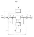
- FIG. 1 shows the principle of an acoustic feedback using the example of a hearing aid 1.
- the hearing aid 1 comprises a microphone 2, which receives an acoustic useful signal 10, converts it into an electrical microphone signal 11 and outputs it to a signal processing unit 3.
- the microphone signal 11 is, among other things, processed and amplified and output as a receiver signal 12 to a receiver 4.
- the electrical receiver signal 12 is again converted into an acoustic output signal 13 and delivered to the eardrum 7 of a hearing aid wearer.
- a suitable phase position and amplitude of the fed-back output signal disturbing feedback whistling occurs.
- the attenuation of the acoustic feedback is low, whereby the problem is exacerbated.
- the acoustic feedback path 14 is digitally reproduced.
- the replication takes place, for example, by means of an adaptive compensation filter 5, which is fed by the signal 12 driving the listener. After filtering in the compensation filter 5, a filtered compensation signal 15 is subtracted from the microphone signal 11. Ideally, the effect of the acoustic feedback path 14 is thereby canceled and there is a feedback-compensated input signal 16 of the signal processing unit 3.
- the filter coefficients of the adaptive compensation filter 5 For effective feedback suppression, adjustment of the filter coefficients of the adaptive compensation filter 5 is required.
- the input signal 16 of the signal processing unit 3 is evaluated by means of an analysis unit 6 and examined for possible feedback.
- the adaptation can cause artifacts, since 5 not optimal adaptive compensation filters 5 additional signal components are generated.
- a feedback whistling may occur.
- such a hearing aid is disclosed, wherein two parallel adaptive compensation filters are used to improve the feedback suppression.
- the stated object is achieved with the hearing device of independent claim 1 and the method of independent claim 8.
- the idea of the invention is to select from a plurality of preset static compensation filters the one appropriate for effective feedback cancellation.
- the invention claims a hearing device for suppressing feedback with a microphone emitting a microphone signal and a receiver receiving a receiver signal by subtracting a compensation signal from the microphone signal.
- the hearing apparatus comprises a plurality of preset static first compensation filters for forming first compensation signals from the receiver signal and a first selection unit which selects a first compensation signal such that a feedback signal caused by the feedback is minimal in the receiver signal.
- the hearing device may additionally comprise an adaptive first compensation filter for forming a further first compensation signal from the receiver signal.
- an adaptive first compensation filter for forming a further first compensation signal from the receiver signal.
- the hearing device may comprise a preset static second compensation filter for forming a second compensation signal from the receiver signal and a second selection unit connected between the microphone and the first selection unit.
- the second selection unit subtracts the second compensation signal from the microphone signal, as a result of which a feedback signal caused by the feedback can be minimized in the receiver signal.
- the second compensation filter can model a mechanical feedback path within the hearing device. This offers the advantage that due to the mechanical structure of the hearing device conditional feedback paths can be compensated.
- the static first compensation filters may have different acoustic feedback paths model. As a result, "typical" feedback paths can be selectively suppressed.
- the filter coefficients of the static first compensation filters can be determined by feedback path measurements.
- the hearing device may be a hearing aid.
- the invention also claims a method for suppressing feedback in a hearing apparatus by subtracting a compensation signal from a microphone signal.
- the method includes forming first compensation signals from a listener signal by preset static first compensation filters and selecting one of the formed first compensation signals such that a feedback signal caused by the feedback is minimal in the listener signal.
- the method comprises the formation of a further first compensation signal from the receiver signal by means of an adaptive first compensation filter.
- the method comprises forming a second compensation signal from the receiver signal by a preset static second compensation filter and subtracting the second compensation signal from the microphone signal, thereby minimizing a feedback signal caused by the feedback in the input signal.
- the second compensation filter can model a mechanical feedback path within the hearing device.
- the static first compensation filters may model different acoustic feedback paths.
- the filter coefficients of the static first compensation filters can be determined by feedback path measurements.
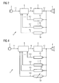
- FIG. 2 shows the principle of the invention by means of a circuit diagram.
- a microphone 2 of a hearing device 1 emits a microphone signal 11 which is picked up by a first selection unit 8.
- the microphone signal 11 is acted on by a feedback signal which is formed as a result of acoustic feedbacks between a receiver 4 of the hearing device 1 and the microphone 2.
- a first compensation signal 151 is subtracted in the selection unit 8. The first compensation signal 151 should ideally completely compensate the feedback signal.
- a plurality of first compensation signals 151 are therefore generated with the aid of static first compensation filters 51 from a receiver signal 12 which is present at the output of a signal processing unit 3 of the hearing device 1.
- the listener signal 12 is also the input signal of the listener 4.
- the first selection unit 8 selects the most suitable compensation signal 151 and outputs the thus feedback-compensated microphone signal as an input signal 16 to the signal processing unit 3.
- the filter coefficients of the static first compensation filters 51 are set to "typical" feedback paths.
- the filter coefficients are metrologically determined by feedback path measurements on the ear of a hearing aid wearer at a hearing care professional.
- the use of static first compensation filters is possible because in the everyday environment of a hearing aid wearer sets a finite number of approximately uniform wear conditions and thus feedback paths. A large part of the feedback-critical situations can thus be "combated”.
- statically operating first compensation filters 51 By using statically operating first compensation filters 51, no adaptation artifacts occur. To avoid artifacts when switching between different first compensation signals 151, instead of a "hard” switching, a controlled cross-fading between the compensation signals 151 can take place.
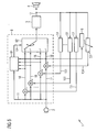
- FIG. 3 shows the diagram of a hearing aid 1 with a microphone 2 for receiving sound and a handset 4 for delivering sound to the eardrum of a hearing aid wearer.
- the microphone signal 11 emitted by the microphone 2 is freed from feedback in a first selection unit 8 and subsequently amplified in a signal processing unit, inter alia, and emitted as a receiver signal 12.
- compensation signals 151 are obtained with the aid of a plurality of static first compensation filters 51, which signals are supplied to the first selection unit 8.
- the compensation signals 151 are each subtracted from the microphone signal 11 and fed as input signals 18 to a first switching unit 82.
- the first switching unit 82 switches through one of the input signals 18 and outputs it as a further input signal 16 to the signal processing unit 3.
- the first switching unit 82 is controlled by means of a first switching signal 19 from a first analysis unit 81.
- the first analysis unit 81 analyzes the input signals 18 of the first switching unit 82 and the microphone signal 11. Based on the analysis, that input signal 18 which has the most effective feedback suppression is selected.
- the analysis unit 81 decides, for example, based on a minimum energy of the input signal 18 or the minimization of a watermark in the input signal 18, which is impressed on the receiver signal 12.
- FIG. 4 shows the principle of the combination of static and adaptive compensation filters on the basis of a circuit diagram.
- a microphone 2 of a hearing device 1 emits a microphone signal 11 which is picked up by a first selection unit 8.
- the microphone signal 11 is acted on by a feedback signal which is formed as a result of acoustic feedbacks between a receiver 4 of the hearing device 1 and the microphone 2.
- a first compensation signal 151 is subtracted in the first selection unit 8.
- the first compensation signal 151 should ideally be equal to the feedback signal.
- a plurality of first compensation signals 151 are therefore generated with the aid of static first compensation filters 51 from a receiver signal 12 which is present at the output of a signal processing unit 3 of the hearing device 1.
- the handset signal 12 is also the input signal of the handset 4.
- an adaptive first compensation filter 53 generates a further first compensation signal 151 from the handset signal 12.
- the first selection unit 8 selects the most suitable and outputs the thus feedback-compensated microphone signal as an input signal 16 to the signal processing unit 3.
- Adaptation artifacts only occur when none of the static first compensation filters 51 produces a better resulting input signal 18 than the adaptive first compensation filter 53.
- an adaptation control of the adaptive first compensation filter 53 can be used in the case of better static first compensation filter 51 whose filter coefficients take over as the starting value of the adaptation.
- FIG. 5 shows the diagram of a hearing aid 1 with a microphone 2 for receiving sound and a handset 4 for delivering sound to the eardrum of a hearing aid wearer.
- the microphone signal 11 delivered by the microphone 2 is freed from feedback in a first selection unit 8 and subsequently amplified in a signal processing unit 3 and delivered as a handset signal 12.
- Compensation signals 151 which are supplied to the first selection unit 8, are obtained from the receiver signal 12 with the aid of a plurality of static first compensation filters 51 and an adaptive first compensation filter 53.
- the compensation signals 151 are each subtracted from the microphone signal 11 and fed as input signal 18 to a first switching unit 82.
- the first switching unit 82 switches through one of the input signals 18 and outputs it as an input signal 16 to the signal processing unit 3.
- the first switching unit 13 is controlled by means of a first switching signal 19 from a first analysis unit 81.
- the first analysis unit 81 analyzes the input signals 18 of the first switching unit 82 and the microphone signal 11. Based on the analysis, that input signal 18 which has the most effective feedback suppression is selected.
- the analysis unit 81 decides, for example, based on a minimum energy of the input signal 18 or the minimization of a watermark in the input signal 18, which is impressed on the receiver signal 12.
- the adaptive first compensation filter 53 is controlled by means of an analysis unit 6.
- the analysis unit 6 evaluates the first compensation signal 151 of the adaptive first compensation filter 53 subtracted from the microphone signal 11 and adjusts the filter coefficients of the adaptive first compensation filter 53 accordingly.
- another mechanical feedback path exists within the hearing aid.
- This path is generally subject to little variation and depends primarily on the design of the hearing aid.
- This mechanical feedback can be suppressed by another static compensation filter separately from the first compensation filters.
- the advantage of this is that, in contrast to an adaptive filter, such a filter can be used in a broadband manner since it does not cause any artifacts due to potential misadaptation of the filter coefficients. Therefore, a higher maximum amplification of the hearing aid can be achieved by canceling the feedback component by housing sound.
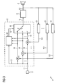
- FIG. 6 the use of an additional static compensation filter is shown in principle.
- the FIG. 6 shows on the basis of a circuit diagram in addition to the at FIG. 4 Components described between the microphone 2 and the first selection unit 8, a second selection unit 9.
- a second compensation signal 152 is formed by a static second compensation filter 52 from the receiver signal 12.
- the filter coefficients of the second compensation filter are selected such that mechanical feedbacks in the hearing aid housing are suppressed.
- the selection unit 9 selects whether the microphone signal 11 or the difference signal between the microphone signal 11 and the second compensation signal 152 is applied as an input signal 17 to the first selection unit 8.
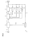
- FIG. 7 is the implementation of the principle FIG. 6 exemplified.
- the FIG. 7 shows the wiring diagram of a
- Hearing aid 1 extended by a static second compensation filter 52 and a second selection unit 9.
- the selection unit 9 comprises a second switching unit 92 and a second analysis unit 91.
- the compensation signal 152 of the second compensation filter 52 is subtracted from the microphone signal 11 and supplied to the second switching unit 92 as an input signal 20.
- the microphone signal 11 is applied to a further input of the switching unit 92 itself.
- the second switching signal 21 of the second analysis unit 92 the second switching unit 92 is controlled. From a comparison of the microphone signal 11 with the input signal 20, which are both supplied to the second analysis unit 91, the second analysis unit 91 detects whether a mechanical feedback is present. Accordingly, the turn-on of the feedback-reduced signal 20 is caused and the second switching unit 92 outputs an output signal 17 to the first selection unit 8.
Abstract
Description
Die Erfindung betrifft eine im Patentanspruch 1 angegebene Hörvorrichtung zur Unterdrückung von Rückkopplungen mit einem ein Mikrofonsignal abgebenden Mikrofon und einem ein Hörersignal aufnehmenden Hörer durch Subtraktion eines Kompensationssignals von dem Mikrofonsignal sowie ein im Patentanspruch 8 angegebenes Verfahren zur Unterdrückung von Rückkopplungen bei einer Hörvorrichtung durch Subtraktion eines Kompensationssignals von einem Mikrofonsignal.The invention relates to a specified in
Ein häufiges Problem bei Hörvorrichtungen ist die Rückkopplung zwischen dem Ausgang der Hörvorrichtung und dem Eingang, die sich als Rückkopplungspfeifen störend bemerkbar macht.
Das Problem besteht nun darin, dass ein Teil des akustischen Ausgangssignals 13 über einen akustischen Rückkopplungspfad 14 zum Eingang des Hörgeräts 1 gelangt, wo es sich mit dem Nutzsignal 10 überlagert und als Summensignal vom Mikrofon 2 aufgenommen wird. Bei geeigneter Phasenlage und Amplitude des rückgekoppelten Ausgangssignals kommt es zum störenden Rückkopplungspfeifen. Insbesondere durch eine offene Hörgeräteversorgung ist die Dämpfung der akustischen Rückkopplung gering, wodurch das Problem verschärft wird.The problem now is that a part of the
Zur Lösung des Problems stehen seit einiger Zeit adaptive Systeme zur Rückkopplungsunterdrückung zur Verfügung. Dabei wird der akustische Rückkopplungspfad 14 digital nachgebildet. Die Nachbildung erfolgt beispielsweise mittels eines adaptiven Kompensationsfilters 5, das von dem Hörer treibenden Signal 12 gespeist wird. Nach der Filterung im Kompensationsfilter 5 wird ein gefiltertes Kompensationssignal 15 vom Mikrofonsignal 11 subtrahiert. Im Idealfall wird die Wirkung des akustischen Rückkopplungspfads 14 dadurch aufgehoben und es entsteht ein rückkopplungskompensiertes Eingangssignal 16 der Signalverarbeitungseinheit 3.To solve the problem adaptive systems for feedback suppression have been available for some time. In this case, the
Für eine effektive Rückkopplungsunterdrückung ist eine Regelung bzw. Anpassung der Filterkoeffizienten des adaptiven Kompensationsfilters 5 erforderlich. Dazu wird mit Hilfe einer Analyseeinheit 6 das Eingangssignal 16 der Signalverarbeitungseinheit 3 ausgewertet und auf mögliche Rückkopplungen untersucht. Durch die Anpassung können Artefakte entstehen, da bei nicht optimal adaptiven Kompensationsfiltern 5 zusätzliche Signalkomponenten erzeugt werden. Außerdem kann bei einem nicht optimal adaptierten Kompensationsfilter 5 ein Rückkopplungspfeifen auftreten. In der
Es ist Aufgabe der Erfindung eine Hörvorrichtung und ein Verfahren zur verbesserten Rückkopplungsunterdrückung anzugeben.It is an object of the invention to provide a hearing apparatus and a method for improved feedback suppression.
Gemäß der Erfindung wird die gestellte Aufgabe mit der Hörvorrichtung des unabhängigen Patentanspruchs 1 und dem Verfahren des unabhängigen Patentanspruchs 8 gelöst.According to the invention, the stated object is achieved with the hearing device of
Die Idee der Erfindung besteht darin, aus einer Mehrzahl von vorab eingestellten statischen Kompensationsfiltern das für eine effektive Rückkopplungsunterdrückung passende auszuwählen.The idea of the invention is to select from a plurality of preset static compensation filters the one appropriate for effective feedback cancellation.
Die Erfindung beansprucht eine Hörvorrichtung zur Unterdrückung von Rückkopplungen mit einem ein Mikrofonsignal abgebenden Mikrofon und einem ein Hörersignal aufnehmenden Hörer durch Subtraktion eines Kompensationssignals von dem Mikrofonsignal. Die Hörvorrichtung umfasst mehrere voreingestellte statische erste Kompensationsfilter zur Bildung von ersten Kompensationssignalen aus dem Hörersignal und eine erste Auswahleinheit, die ein erstes Kompensationssignal derart auswählt, dass ein durch die Rückkopplung verursachtes Rückkopplungssignal im Hörersignal minimal ist. Vorteilhaft daran ist, dass keine Adaptions-Artefakte auftreten können.The invention claims a hearing device for suppressing feedback with a microphone emitting a microphone signal and a receiver receiving a receiver signal by subtracting a compensation signal from the microphone signal. The hearing apparatus comprises a plurality of preset static first compensation filters for forming first compensation signals from the receiver signal and a first selection unit which selects a first compensation signal such that a feedback signal caused by the feedback is minimal in the receiver signal. The advantage of this is that no adaptation artifacts can occur.
In einer Weiterbildung kann die Hörvorrichtung zusätzlich ein adaptives erstes Kompensationsfilter zur Bildung eines weiteren ersten Kompensationssignals aus dem Hörersignal umfassen. Dadurch treten Adaptionsartefakte nur dann auf, wenn keines der statischen ersten Kompensationsfilter ein besseres resultierendes Signal erzeugt als das adaptive erste Kompensationsfilter.In a further development, the hearing device may additionally comprise an adaptive first compensation filter for forming a further first compensation signal from the receiver signal. As a result, adaptation artifacts occur only when none of the static first compensation filters produces a better resulting signal than the adaptive first compensation filter.
In einer weiteren Ausführungsform kann die Hörvorrichtung ein voreingestelltes statisches zweites Kompensationsfilter zur Bildung eines zweiten Kompensationssignals aus dem Hörersignal und eine zwischen dem Mikrofon und der ersten Auswahleinheit geschaltete zweite Auswahleinheit umfassen. Die zweite Auswahleinheit subtrahiert das zweite Kompensationssignal von dem Mikrofonsignal, wenn dadurch ein durch die Rückkopplung verursachtes Rückkopplungssignal im Hörersignal minimiert werden können.In a further embodiment, the hearing device may comprise a preset static second compensation filter for forming a second compensation signal from the receiver signal and a second selection unit connected between the microphone and the first selection unit. The second selection unit subtracts the second compensation signal from the microphone signal, as a result of which a feedback signal caused by the feedback can be minimized in the receiver signal.
Des Weiteren kann das zweite Kompensationsfilter einen mechanischen Rückkopplungspfad innerhalb der Hörvorrichtung modellieren. Dies bietet den Vorteil, dass durch den mechanischen Aufbau der Hörvorrichtung bedingte Rückkopplungspfade kompensierbar sind.Furthermore, the second compensation filter can model a mechanical feedback path within the hearing device. This offers the advantage that due to the mechanical structure of the hearing device conditional feedback paths can be compensated.
In einer weiteren Ausführungsform können die statischen ersten Kompensationsfilter unterschiedliche akustische Rückkopplungspfade modellieren. Dadurch können "typische" Rückkopplungspfade gezielt unterdrückt werden.In a further embodiment, the static first compensation filters may have different acoustic feedback paths model. As a result, "typical" feedback paths can be selectively suppressed.
In einer Weiterbildung der Erfindung können die Filterkoeffizienten der statischen ersten Kompensationsfilter durch Rückkopplungspfadmessungen bestimmt werden. Vorteilhaft daran ist die individuelle Anpassung der Filterkoeffizienten an die Nutzungssituation der Hörvorrichtung.In a development of the invention, the filter coefficients of the static first compensation filters can be determined by feedback path measurements. An advantage of this is the individual adaptation of the filter coefficients to the usage situation of the hearing device.
Außerdem kann die Hörvorrichtung ein Hörgerät sein.In addition, the hearing device may be a hearing aid.
Die Erfindung beansprucht auch ein Verfahren zur Unterdrückung von Rückkopplungen bei einer Hörvorrichtung durch Subtraktion eines Kompensationssignals von einem Mikrofonsignal. Das Verfahren umfasst eine Bildung von ersten Kompensationssignalen aus einem Hörersignal durch voreingestellte statische erste Kompensationsfilter und eine Auswahl eines der gebildeten ersten Kompensationssignale derart, dass ein durch die Rückkopplung verursachtes Rückkopplungssignal im Hörersignal minimal ist.The invention also claims a method for suppressing feedback in a hearing apparatus by subtracting a compensation signal from a microphone signal. The method includes forming first compensation signals from a listener signal by preset static first compensation filters and selecting one of the formed first compensation signals such that a feedback signal caused by the feedback is minimal in the listener signal.
Das Verfahren umfasst in einer Weiterbildung eine Bildung eines weiteren ersten Kompensationssignals aus dem Hörersignal durch ein adaptives erstes Kompensationsfilter.In one development, the method comprises the formation of a further first compensation signal from the receiver signal by means of an adaptive first compensation filter.
In einer weiteren Ausführungsform umfasst das Verfahren eine Bildung eines zweiten Kompensationssignals aus dem Hörersignal durch ein voreingestelltes statisches zweites Kompensationsfilter und eine Subtraktion des zweiten Kompensationssignals von dem Mikrofonsignal, wenn dadurch ein durch die Rückkopplung verursachtes Rückkopplungssignal im Eingangssignal minimierbar ist.In a further embodiment, the method comprises forming a second compensation signal from the receiver signal by a preset static second compensation filter and subtracting the second compensation signal from the microphone signal, thereby minimizing a feedback signal caused by the feedback in the input signal.
Des Weiteren kann das zweite Kompensationsfilter einen mechanischen Rückkopplungspfad innerhalb der Hörvorrichtung modellieren.Furthermore, the second compensation filter can model a mechanical feedback path within the hearing device.
In einer weiteren Ausführungsform können die statischen ersten Kompensationsfilter unterschiedliche akustische Rückkopplungspfade modellieren.In another embodiment, the static first compensation filters may model different acoustic feedback paths.
Außerdem können die Filterkoeffizienten der statischen ersten Kompensationsfilter durch Rückkopplungspfadmessungen bestimmt werden.In addition, the filter coefficients of the static first compensation filters can be determined by feedback path measurements.
Weitere Besonderheiten und Vorteile der Erfindung werden aus den nachfolgenden Erläuterungen mehrerer Ausführungsbeispiele anhand von schematischen Zeichnungen ersichtlich.Other features and advantages of the invention will become apparent from the following explanations of several embodiments with reference to schematic drawings.
Es zeigen:
- Figur 1:
- ein Schaltbild eines Hörgeräts mit Rückkopplungs- unterdrückung gemäß Stand der Technik,
- Figur 2:
- ein Prinzipschaltbild eines Hörgeräts mit mehreren statischen Kompensationsfiltern,
- Figur 3:
- ein Schaltbild eines weiteren Hörgeräts mit mehre- ren statischen Kompensationsfiltern,
- Figur 4:
- ein Prinzipschaltbild eines Hörgeräts mit mehreren statischen Kompensationsfiltern und einem adapti- ven Kompensationsfilter,
- Figur 5:
- ein Schaltbild eines weiteren Hörgeräts mit mehre- ren statischen Kompensationsfiltern und einem adaptiven Kompensationsfilter,
- Figur 6:
- ein Prinzipschaltbild eines Hörgeräts mit mehreren statischen Kompensationsfiltern, einem adaptiven Kompensationsfilter und einem zusätzlichen breit- bandigen statischen Kompensationsfilter und
- Figur 7:
- ein Schaltbild eines weiteren Hörgeräts mit mehre- ren statischen Kompensationsfiltern, einem adapti- ven Kompensationsfilter und einem zusätzlichen breitbandigen statischen Kompensationsfilter.
- FIG. 1:
- 1 is a circuit diagram of a hearing aid with feedback suppression according to the prior art;
- FIG. 2:
- a block diagram of a hearing aid with several static compensation filters,
- FIG. 3:
- a circuit diagram of another hearing aid with several static compensation filters,
- FIG. 4:
- a block diagram of a hearing aid with several static compensation filters and an adaptive compensation filter,
- FIG. 5:
- a circuit diagram of a further hearing aid with several static compensation filters and an adaptive compensation filter,
- FIG. 6:
- a schematic diagram of a hearing aid with multiple static compensation filters, an adaptive compensation filter and an additional broadband static compensation filter and
- FIG. 7:
- a circuit diagram of another hearing aid with several static compensation filters, an adaptive compensation filter and an additional broadband static compensation filter.
In den folgenden Ausführungsbeispielen wird die Erfindung am Beispiel eines Hörgeräts erläutert. Die erklärenden Ausführungen gelten selbstverständlich auch für andere Hörvorrichtungen.In the following embodiments, the invention will be explained using the example of a hearing aid. The explanatory remarks of course apply to other hearing aids.
Erfindungsgemäß werden daher mehrere erste Kompensationssignale 151 mit Hilfe von statischen ersten Kompensationsfiltern 51 aus einem Hörersignal 12 erzeugt, das am Ausgang einer Signalverarbeitungseinheit 3 des Hörgeräts 1 anliegt. Das Hörersignal 12 ist auch das Eingangssignal des Hörers 4. Aus einer Analyse des Mikrofonsignals 11 und der Kompensationssignale 151 wählt die erste Auswahleinheit 8 das am besten geeignete Kompensationssignal 151 aus und gibt das damit rückkopplungskompensierte Mikrofonsignal als Eingangssignal 16 an die Signalverarbeitungseinheit 3 ab.According to the invention, a plurality of first compensation signals 151 are therefore generated with the aid of static first compensation filters 51 from a
Die Filterkoeffizienten der statischen ersten Kompensationsfilter 51 werden auf "typische" Rückkopplungspfade eingestellt. Die Filterkoeffizienten werden beispielsweise durch Rückkopplungspfadmessungen am Ohr eines Hörgerätträgers bei einem Hörgeräteakustiker messtechnisch bestimmt. Die Verwendung von statischen ersten Kompensationsfiltern ist möglich, weil sich im alltäglichen Umfeld eines Hörgeräteträgers eine endliche Anzahl von annähernd gleichbleibenden Tragebedingungen und damit Rückkopplungspfaden einstellt. Ein großer Teil der rückkopplungskritischen Situationen kann damit "bekämpft" werden.The filter coefficients of the static first compensation filters 51 are set to "typical" feedback paths. For example, the filter coefficients are metrologically determined by feedback path measurements on the ear of a hearing aid wearer at a hearing care professional. The use of static first compensation filters is possible because in the everyday environment of a hearing aid wearer sets a finite number of approximately uniform wear conditions and thus feedback paths. A large part of the feedback-critical situations can thus be "combated".
Durch die Verwendung von statisch arbeitenden ersten Kompensationsfiltern 51 treten keine Adaptions-Artefakte auf. Um Artefakte beim Umschalten zwischen unterschiedlichen ersten Kompensationssignalen 151 zu vermeiden, kann anstelle eines "harten" Umschaltens auch eine gesteuerte Überblendung zwischen den Kompensationssignalen 151 erfolgen.By using statically operating first compensation filters 51, no adaptation artifacts occur. To avoid artifacts when switching between different first compensation signals 151, instead of a "hard" switching, a controlled cross-fading between the compensation signals 151 can take place.
Eine Umsetzung des Prinzips gemäß
In der ersten Auswahleinheit 8 werden die Kompensationssignale 151 jeweils von dem Mikrofonsignal 11 subtrahiert und als Eingangssignale 18 einer ersten Schalteinheit 82 zugeführt. Die erste Schalteinheit 82 schaltet eines der Eingangssignale 18 durch und gibt es als weiteres Eingangssignal 16 an die Signalverarbeitungseinheit 3 ab. Die erste Schalteinheit 82 wird mit Hilfe eines ersten Schaltsignals 19 von einer ersten Analyseeinheit 81 gesteuert. Dazu analysiert die erste Analyseeinheit 81 die Eingangssignale 18 der ersten Schalteinheit 82 und das Mikrofonsignal 11. Auf Grund der Analyse wird dasjenige Eingangssignal 18 ausgewählt, das die effektivste Rückkopplungsunterdrückung aufweist. Die Analyseeinheit 81 entscheidet beispielsweise auf Basis einer minimalen Energie des Eingangssignals 18 oder der Minimierung eines Wasserzeichens im Eingangsignal 18, das auf das Hörersignal 12 aufgeprägt wird.In the
Um auch Rückkopplungspfaden begegnen zu können, die nicht statisch in einem Hörgerät speicherbar sind, ist es möglich die statischen ersten Kompensationsfiltern 51 mit einem zusätzliches adaptives erstes Kompensationsfilter zu kombinieren.In order to be able to encounter feedback paths that are not statically storable in a hearing aid, it is possible to combine the static first compensation filters 51 with an additional adaptive first compensation filter.
Erfindungsgemäß werden daher mehrere erste Kompensationssignale 151 mit Hilfe von statischen ersten Kompensationsfiltern 51 aus einem Hörersignal 12 erzeugt, das am Ausgang einer Signalverarbeitungseinheit 3 des Hörgeräts 1 anliegt. Das Hörersignal 12 ist auch das Eingangssignal des Hörers 4. Zusätzlich erzeugt ein adaptives erstes Kompensationsfilter 53 ein weiteres erstes Kompensationssignal 151 aus dem Hörersignal 12.According to the invention, a plurality of first compensation signals 151 are therefore generated with the aid of static first compensation filters 51 from a
Aus einer Analyse des Mikrofonsignals 11 und der Kompensationssignale 151 wählt die erste Auswahleinheit 8 das am besten geeignete aus und gibt das damit rückkopplungskompensierte Mikrofonsignal als Eingangssignal 16 an die Signalverarbeitungseinheit 3 ab.From an analysis of the
Adaptionsartefakte treten nur dann auf, wenn keiner der statischen ersten Kompensationsfilter 51 ein besseres resultierendes Eingangssignal 18 erzeugt als das adaptive erste Kompensationsfilter 53. Außerdem kann eine Adaptionskontrolle des adaptiven ersten Kompensationsfilters 53 im Falle eines besseren statischen ersten Kompensationsfilters 51 dessen Filterkoeffizienten als Startwert der Adaption übernehmen.Adaptation artifacts only occur when none of the static first compensation filters 51 produces a better resulting
Eine Umsetzung des Prinzips gemäß
In der ersten Auswahleinheit 8 werden die Kompensationssignale 151 jeweils von dem Mikrofonsignal 11 subtrahiert und als Eingangssignal 18 einer ersten Schalteinheit 82 zugeführt. Die erste Schalteinheit 82 schaltet eines der Eingangssignale 18 durch und gibt es als Eingangssignal 16 an die Signalverarbeitungseinheit 3 ab. Die erste Schalteinheit 13 wird mit Hilfe eines ersten Schaltsignals 19 von einer ersten Analyseeinheit 81 gesteuert. Dazu analysiert die erste Analyseeinheit 81 die Eingangssignale 18 der ersten Schalteinheit 82 und das Mikrofonsignal 11. Auf Grund der Analyse wird dasjenige Eingangssignal 18 ausgewählt, das die effektivste Rückkopplungsunterdrückung aufweist. Die Analyseeinheit 81 entscheidet beispielsweise auf Basis einer minimalen Energie des Eingangssignals 18 oder der Minimierung eines Wasserzeichens im Eingangsignal 18, das auf das Hörersignal 12 aufgeprägt wird.In the
Das adaptive erste Kompensationsfilter 53 wird mit Hilfe einer Analyseeinheit 6 gesteuert. Die Analyseeinheit 6 wertet das vom Mikrofonsignal 11 subtrahierte erste Kompensationssignal 151 des adaptiven ersten Kompensationsfilters 53 aus und stellt entsprechend die Filterkoeffizienten des adaptiven ersten Kompensationsfilters 53 ein.The adaptive
Zusätzlich zu dem sich verändernden externen akustischen Rückkopplungspfad existiert innerhalb des Hörgeräts ein weiterer, mechanischer Rückkopplungspfad. Dieser Pfad unterliegt im Allgemeinen nur geringen Schwankungen und hängt in erster Linie von der Konstruktion des Hörgeräts ab. Diese mechanische Rückkopplung lässt sich durch ein weiteres statisches Kompensationsfilter getrennt von den ersten Kompensationsfiltern unterdrücken. Vorteilhaft daran ist, dass ein solches Filter im Gegensatz zu einem adaptiven Filter breitbandig verwendet werden kann, da es keine Artefakte durch potenzielle Fehladaption der Filterkoeffizienten hervorruft. Daher kann eine höhere maximale Verstärkung des Hörgerätes durch Auslöschung des Rückkopplungsanteils durch Gehäuseschall erzielt werden.In addition to the changing external acoustic feedback path, another mechanical feedback path exists within the hearing aid. This path is generally subject to little variation and depends primarily on the design of the hearing aid. This mechanical feedback can be suppressed by another static compensation filter separately from the first compensation filters. The advantage of this is that, in contrast to an adaptive filter, such a filter can be used in a broadband manner since it does not cause any artifacts due to potential misadaptation of the filter coefficients. Therefore, a higher maximum amplification of the hearing aid can be achieved by canceling the feedback component by housing sound.
In
In
Hörgeräts 1 gemäß
- 11
- Hörgeräthearing Aid
- 22
- Mikrofonmicrophone
- 33
- SignalverarbeitungseinheitSignal processing unit
- 44
- Hörerreceiver
- 55
- adaptives Kompensationsfilteradaptive compensation filter
- 5151
- statisches erstes Kompensationsfilterstatic first compensation filter
- 5252
- statisches erstes Kompensationsfilterstatic first compensation filter
- 5353
- adaptives erstes Kompensationsfilteradaptive first compensation filter
- 66
- Analyseeinheitanalysis unit
- 77
- Trommelfelleardrum
- 88th
- erste Auswahleinheitfirst selection unit
- 8181
- erste Analyseeinheitfirst analysis unit
- 8282
- erste Schalteinheitfirst switching unit
- 99
- zweite Auswahleinheitsecond selection unit
- 9191
- zweite Analyseeinheitsecond analysis unit
- 9292
- zweite Schalteinheitsecond switching unit
- 1010
- Nutzsignalpayload
- 1111
- Mikrofonsignalmicrophone signal
- 1212
- Hörersignalearpiece signal
- 1313
- Ausgangssignaloutput
- 1414
- akustischer Rückkopplungspfadacoustic feedback path
- 1515
- Kompensationssignalcompensation signal
- 151151
- erstes Kompensationssignalfirst compensation signal
- 152152
- zweites Kompensationssignalsecond compensation signal
- 1616
-
Eingangssignal der Signalverarbeitungseinheit 3Input signal of the
signal processing unit 3 - 1717
-
Ausgangssignal der zweiten Auswahleinheit 9Output signal of the
second selection unit 9 - 1818
-
Eingangssignal der ersten Schalteinheit 82Input signal of the
first switching unit 82 - 1919
- erstes Schaltsignalfirst switching signal
- 2020
-
Eingangssignal der zweiten Schalteinheit 92Input signal of the
second switching unit 92 - 2121
- zweites Schaltsignalsecond switching signal
Claims (13)
- Hearing apparatus (1) for suppressing feedback, having a microphone (2) emitting a microphone signal (11) and a receiver (4) picking up a receiver signal (12), by subtracting a compensation signal (151, 152) from the microphone signal (11, 17),
characterised by:- a number of preset static first compensation filters (51) for forming first compensation signals (151) from the receiver signal (12) and- a first selection unit (8), which selects a first compensation signal (151) such that a feedback signal caused by the feedback is minimal in the receiver signal (12). - Hearing apparatus (1) according to claim 1,
characterised by:- an adaptive first compensation filter (53) for forming a further first compensation signal (151) from the receiver signal (12). - Hearing apparatus (1) according to claim 1 or 2, characterised by:- a preset static second compensation filter (52) for forming a second compensation signal (152) from the receiver signal (12) and- a second selection unit (9) connected between the microphone (2) and the first selection unit (8), which subtracts the second compensation signal (152) from the microphone signal (11), if this allows a feedback signal caused by the feedback to be minimised in the receiver signal (12).
- Hearing apparatus (1) according to claim 3,
characterised in that
the second compensation filter (52) models a mechanical feedback path within the hearing apparatus (1). - Hearing apparatus (1) according to one of the preceding claims,
characterised in that the static first compensation filters (51) model different acoustic feedback paths. - Hearing apparatus (1) according to claim 5,
characterised in that the filter coefficients of the static first compensation filters (51) can be determined by means of feedback path measurements. - Hearing apparatus (1) according to one of the preceding claims,
characterised in that the hearing apparatus is a hearing device. - Method for suppressing feedback in a hearing apparatus (1) by subtracting a compensation signal (151, 152) from a microphone signal (11, 17),
characterised by:- forming first compensation signals (151) from a receiver signal (12) by means of preset static first compensation filters (51) and- selecting one of the formed first compensation signals (151) such that a feedback signal caused by the feedback is minimal in the receiver signal (12). - Method according to claim 8,
characterised by:- forming a further first compensation signal (151) from the receiver signal (12) by means of an adaptive first compensation filter (53). - Method according to claim 8 or 9,
characterised by:- forming a second compensation signal (152) from the receiver signal (12) by means of a preset static second compensation filter (52) and- subtracting the second compensation signal (152) from the microphone signal (11), if this allows a feedback signal caused by the feedback to be minimised in the receiver signal (12). - Method according to claim 10,
characterised in that the second compensation filter (52) models a mechanical feedback path within the hearing apparatus (1). - Method according to one of claims 8 to 11,
characterised in that the static first compensation filters (51) model different acoustic feedback paths. - Method according to claim 12,
characterised in that the filter coefficients of the static first compensation filters (51) are determined by means of feedback path measurements.
Applications Claiming Priority (1)
| Application Number | Priority Date | Filing Date | Title |
|---|---|---|---|
| DE102009031135A DE102009031135A1 (en) | 2009-06-30 | 2009-06-30 | Hearing apparatus and method for suppressing feedback |
Publications (2)
| Publication Number | Publication Date |
|---|---|
| EP2276272A1 EP2276272A1 (en) | 2011-01-19 |
| EP2276272B1 true EP2276272B1 (en) | 2011-07-06 |
Family
ID=42332775
Family Applications (1)
| Application Number | Title | Priority Date | Filing Date |
|---|---|---|---|
| EP10159896A Not-in-force EP2276272B1 (en) | 2009-06-30 | 2010-04-14 | Hearing aid and method for suppressing feedback |
Country Status (5)
| Country | Link |
|---|---|
| US (1) | US20100329493A1 (en) |
| EP (1) | EP2276272B1 (en) |
| AT (1) | ATE515898T1 (en) |
| DE (1) | DE102009031135A1 (en) |
| DK (1) | DK2276272T3 (en) |
Families Citing this family (5)
| Publication number | Priority date | Publication date | Assignee | Title |
|---|---|---|---|---|
| DE102010009459B4 (en) * | 2010-02-26 | 2012-01-19 | Siemens Medical Instruments Pte. Ltd. | Hearing device with parallel operated feedback reduction filters and method |
| DK2541973T3 (en) * | 2011-06-27 | 2014-07-14 | Oticon As | Feedback control in a listening device |
| EP2613567B1 (en) * | 2012-01-03 | 2014-07-23 | Oticon A/S | A method of improving a long term feedback path estimate in a listening device |
| WO2014141205A1 (en) | 2013-03-15 | 2014-09-18 | Cochlear Limited | Filtering well-defined feedback from a hard-coupled vibrating transducer |
| EP3002959B1 (en) * | 2014-10-02 | 2019-02-06 | Oticon A/s | Feedback estimation based on deterministic sequences |
Family Cites Families (11)
| Publication number | Priority date | Publication date | Assignee | Title |
|---|---|---|---|---|
| DK164349C (en) * | 1989-08-22 | 1992-11-02 | Oticon As | HEARING DEVICE WITH BACKUP COMPENSATION |
| US6072884A (en) | 1997-11-18 | 2000-06-06 | Audiologic Hearing Systems Lp | Feedback cancellation apparatus and methods |
| US6831986B2 (en) * | 2000-12-21 | 2004-12-14 | Gn Resound A/S | Feedback cancellation in a hearing aid with reduced sensitivity to low-frequency tonal inputs |
| DE10223544C1 (en) * | 2002-05-27 | 2003-07-24 | Siemens Audiologische Technik | Amplifier device for hearing aid with microphone and pick-up coil inputs, has amplifier provided with separate filters for acoustic and inductive feedback compensation |
| DE10242700B4 (en) * | 2002-09-13 | 2006-08-03 | Siemens Audiologische Technik Gmbh | Feedback compensator in an acoustic amplification system, hearing aid, method for feedback compensation and application of the method in a hearing aid |
| DE10245667B4 (en) * | 2002-09-30 | 2004-12-30 | Siemens Audiologische Technik Gmbh | Feedback compensator in an acoustic amplification system, hearing aid, method for feedback compensation and application of the method in a hearing aid |
| WO2005081584A2 (en) * | 2004-02-20 | 2005-09-01 | Gn Resound A/S | Hearing aid with feedback cancellation |
| US8374367B2 (en) * | 2006-06-23 | 2013-02-12 | Gn Resound A/S | Hearing aid with a flexible elongated member |
| US20100027823A1 (en) * | 2006-10-10 | 2010-02-04 | Georg-Erwin Arndt | Hearing aid having an occlusion reduction unit and method for occlusion reduction |
| WO2009124550A1 (en) * | 2008-04-10 | 2009-10-15 | Gn Resound A/S | An audio system with feedback cancellation |
| US8243939B2 (en) * | 2008-12-30 | 2012-08-14 | Gn Resound A/S | Hearing instrument with improved initialisation of parameters of digital feedback suppression circuitry |
-
2009
- 2009-06-30 DE DE102009031135A patent/DE102009031135A1/en not_active Withdrawn
-
2010
- 2010-04-14 DK DK10159896.9T patent/DK2276272T3/en active
- 2010-04-14 AT AT10159896T patent/ATE515898T1/en active
- 2010-04-14 EP EP10159896A patent/EP2276272B1/en not_active Not-in-force
- 2010-06-30 US US12/826,855 patent/US20100329493A1/en not_active Abandoned
Also Published As
| Publication number | Publication date |
|---|---|
| ATE515898T1 (en) | 2011-07-15 |
| US20100329493A1 (en) | 2010-12-30 |
| EP2276272A1 (en) | 2011-01-19 |
| DK2276272T3 (en) | 2011-10-24 |
| DE102009031135A1 (en) | 2011-01-27 |
Similar Documents
| Publication | Publication Date | Title |
|---|---|---|
| DE10228632B3 (en) | Directional hearing with binaural hearing aid care | |
| DE102005020317B4 (en) | Automatic gain adjustment on a hearing aid | |
| EP1737270B2 (en) | Hearing assistance providing feedback suppression | |
| EP1853089A2 (en) | Method for elimination of feedback and for spectral expansion in hearing aids | |
| EP2276272B1 (en) | Hearing aid and method for suppressing feedback | |
| EP1456839B1 (en) | Method and device for the suppression of periodic interference signals | |
| DE102007033484A1 (en) | hearing Aid | |
| DE102009010892A1 (en) | Apparatus and method for reducing impact sound effects in hearing devices with active occlusion reduction | |
| EP1367856B1 (en) | Method and apparatus for feedback reduction in hearing systems | |
| DE102010041653A1 (en) | Method and apparatus for frequency compression with selective frequency shift | |
| DE102011006129B4 (en) | Hearing device with feedback suppression device and method for operating the hearing device | |
| EP1542500B1 (en) | Hearing aid with noise suppression and corresponding method for noise suppression | |
| EP3355592B1 (en) | Method for operating a binaural hearing aid system | |
| EP2200341B1 (en) | Method for operating a hearing aid and hearing aid with a source separation device | |
| DE102010006154B4 (en) | Hearing aid with frequency shift and associated method | |
| EP1406469B1 (en) | Feedback compensator in acoustic amplifying systems, hearing-aid, method for feedback compensation and use of said method in hearing-aids | |
| DE102010025918B4 (en) | Method for operating a hearing aid and hearing aid with variable frequency shift | |
| EP3319234A1 (en) | Method for operating a hearing aid | |
| EP1351550A1 (en) | Method for adapting a signal amplification in a hearing aid and a hearing aid | |
| DE102005019149B3 (en) | Hearing aid system with compensation for acoustic and electromagnetic feedback signals and having a delay member between the receiver and the signal processor | |
| DE102019213810B3 (en) | Method for operating a hearing aid and hearing aid | |
| DE102017203631B3 (en) | Method for frequency distortion of an audio signal | |
| DE102008058496B4 (en) | Filter bank system with specific stop attenuation components for a hearing device | |
| DE102021103769B4 (en) | Methods for signal processing | |
| DE102021205251A1 (en) | Method and device for frequency-selective processing of an audio signal with low latency |
Legal Events
| Date | Code | Title | Description |
|---|---|---|---|
| PUAI | Public reference made under article 153(3) epc to a published international application that has entered the european phase |
Free format text: ORIGINAL CODE: 0009012 |
|
| 17P | Request for examination filed |
Effective date: 20101018 |
|
| AK | Designated contracting states |
Kind code of ref document: A1 Designated state(s): AT BE BG CH CY CZ DE DK EE ES FI FR GB GR HR HU IE IS IT LI LT LU LV MC MK MT NL NO PL PT RO SE SI SK SM TR |
|
| AX | Request for extension of the european patent |
Extension state: AL BA ME RS |
|
| GRAP | Despatch of communication of intention to grant a patent |
Free format text: ORIGINAL CODE: EPIDOSNIGR1 |
|
| RIC1 | Information provided on ipc code assigned before grant |
Ipc: H04R 25/00 20060101AFI20110113BHEP |
|
| GRAS | Grant fee paid |
Free format text: ORIGINAL CODE: EPIDOSNIGR3 |
|
| GRAA | (expected) grant |
Free format text: ORIGINAL CODE: 0009210 |
|
| AK | Designated contracting states |
Kind code of ref document: B1 Designated state(s): AT BE BG CH CY CZ DE DK EE ES FI FR GB GR HR HU IE IS IT LI LT LU LV MC MK MT NL NO PL PT RO SE SI SK SM TR |
|
| REG | Reference to a national code |
Ref country code: GB Ref legal event code: FG4D Free format text: NOT ENGLISH |
|
| REG | Reference to a national code |
Ref country code: CH Ref legal event code: NV Representative=s name: SIEMENS SCHWEIZ AG Ref country code: CH Ref legal event code: EP |
|
| REG | Reference to a national code |
Ref country code: IE Ref legal event code: FG4D Free format text: LANGUAGE OF EP DOCUMENT: GERMAN |
|
| REG | Reference to a national code |
Ref country code: DE Ref legal event code: R096 Ref document number: 502010000049 Country of ref document: DE Effective date: 20110825 |
|
| REG | Reference to a national code |
Ref country code: DK Ref legal event code: T3 |
|
| REG | Reference to a national code |
Ref country code: NL Ref legal event code: VDEP Effective date: 20110706 |
|
| PG25 | Lapsed in a contracting state [announced via postgrant information from national office to epo] |
Ref country code: SI Free format text: LAPSE BECAUSE OF FAILURE TO SUBMIT A TRANSLATION OF THE DESCRIPTION OR TO PAY THE FEE WITHIN THE PRESCRIBED TIME-LIMIT Effective date: 20110706 |
|
| PG25 | Lapsed in a contracting state [announced via postgrant information from national office to epo] |
Ref country code: LT Free format text: LAPSE BECAUSE OF FAILURE TO SUBMIT A TRANSLATION OF THE DESCRIPTION OR TO PAY THE FEE WITHIN THE PRESCRIBED TIME-LIMIT Effective date: 20110706 Ref country code: NL Free format text: LAPSE BECAUSE OF FAILURE TO SUBMIT A TRANSLATION OF THE DESCRIPTION OR TO PAY THE FEE WITHIN THE PRESCRIBED TIME-LIMIT Effective date: 20110706 Ref country code: SE Free format text: LAPSE BECAUSE OF FAILURE TO SUBMIT A TRANSLATION OF THE DESCRIPTION OR TO PAY THE FEE WITHIN THE PRESCRIBED TIME-LIMIT Effective date: 20110706 Ref country code: HR Free format text: LAPSE BECAUSE OF FAILURE TO SUBMIT A TRANSLATION OF THE DESCRIPTION OR TO PAY THE FEE WITHIN THE PRESCRIBED TIME-LIMIT Effective date: 20110706 Ref country code: NO Free format text: LAPSE BECAUSE OF FAILURE TO SUBMIT A TRANSLATION OF THE DESCRIPTION OR TO PAY THE FEE WITHIN THE PRESCRIBED TIME-LIMIT Effective date: 20111006 Ref country code: PT Free format text: LAPSE BECAUSE OF FAILURE TO SUBMIT A TRANSLATION OF THE DESCRIPTION OR TO PAY THE FEE WITHIN THE PRESCRIBED TIME-LIMIT Effective date: 20111107 Ref country code: IS Free format text: LAPSE BECAUSE OF FAILURE TO SUBMIT A TRANSLATION OF THE DESCRIPTION OR TO PAY THE FEE WITHIN THE PRESCRIBED TIME-LIMIT Effective date: 20111106 Ref country code: FI Free format text: LAPSE BECAUSE OF FAILURE TO SUBMIT A TRANSLATION OF THE DESCRIPTION OR TO PAY THE FEE WITHIN THE PRESCRIBED TIME-LIMIT Effective date: 20110706 |
|
| REG | Reference to a national code |
Ref country code: IE Ref legal event code: FD4D |
|
| PG25 | Lapsed in a contracting state [announced via postgrant information from national office to epo] |
Ref country code: CY Free format text: LAPSE BECAUSE OF FAILURE TO SUBMIT A TRANSLATION OF THE DESCRIPTION OR TO PAY THE FEE WITHIN THE PRESCRIBED TIME-LIMIT Effective date: 20110706 Ref country code: PL Free format text: LAPSE BECAUSE OF FAILURE TO SUBMIT A TRANSLATION OF THE DESCRIPTION OR TO PAY THE FEE WITHIN THE PRESCRIBED TIME-LIMIT Effective date: 20110706 Ref country code: GR Free format text: LAPSE BECAUSE OF FAILURE TO SUBMIT A TRANSLATION OF THE DESCRIPTION OR TO PAY THE FEE WITHIN THE PRESCRIBED TIME-LIMIT Effective date: 20111007 Ref country code: LV Free format text: LAPSE BECAUSE OF FAILURE TO SUBMIT A TRANSLATION OF THE DESCRIPTION OR TO PAY THE FEE WITHIN THE PRESCRIBED TIME-LIMIT Effective date: 20110706 |
|
| PG25 | Lapsed in a contracting state [announced via postgrant information from national office to epo] |
Ref country code: CZ Free format text: LAPSE BECAUSE OF FAILURE TO SUBMIT A TRANSLATION OF THE DESCRIPTION OR TO PAY THE FEE WITHIN THE PRESCRIBED TIME-LIMIT Effective date: 20110706 Ref country code: IE Free format text: LAPSE BECAUSE OF FAILURE TO SUBMIT A TRANSLATION OF THE DESCRIPTION OR TO PAY THE FEE WITHIN THE PRESCRIBED TIME-LIMIT Effective date: 20110706 Ref country code: SK Free format text: LAPSE BECAUSE OF FAILURE TO SUBMIT A TRANSLATION OF THE DESCRIPTION OR TO PAY THE FEE WITHIN THE PRESCRIBED TIME-LIMIT Effective date: 20110706 |
|
| PLBE | No opposition filed within time limit |
Free format text: ORIGINAL CODE: 0009261 |
|
| STAA | Information on the status of an ep patent application or granted ep patent |
Free format text: STATUS: NO OPPOSITION FILED WITHIN TIME LIMIT |
|
| PG25 | Lapsed in a contracting state [announced via postgrant information from national office to epo] |
Ref country code: EE Free format text: LAPSE BECAUSE OF FAILURE TO SUBMIT A TRANSLATION OF THE DESCRIPTION OR TO PAY THE FEE WITHIN THE PRESCRIBED TIME-LIMIT Effective date: 20110706 Ref country code: IT Free format text: LAPSE BECAUSE OF FAILURE TO SUBMIT A TRANSLATION OF THE DESCRIPTION OR TO PAY THE FEE WITHIN THE PRESCRIBED TIME-LIMIT Effective date: 20110706 Ref country code: RO Free format text: LAPSE BECAUSE OF FAILURE TO SUBMIT A TRANSLATION OF THE DESCRIPTION OR TO PAY THE FEE WITHIN THE PRESCRIBED TIME-LIMIT Effective date: 20110706 |
|
| 26N | No opposition filed |
Effective date: 20120411 |
|
| PGFP | Annual fee paid to national office [announced via postgrant information from national office to epo] |
Ref country code: DE Payment date: 20120618 Year of fee payment: 3 Ref country code: DK Payment date: 20120418 Year of fee payment: 3 |
|
| REG | Reference to a national code |
Ref country code: DE Ref legal event code: R097 Ref document number: 502010000049 Country of ref document: DE Effective date: 20120411 |
|
| PGFP | Annual fee paid to national office [announced via postgrant information from national office to epo] |
Ref country code: FR Payment date: 20120507 Year of fee payment: 3 |
|
| BERE | Be: lapsed |
Owner name: SIEMENS MEDICAL INSTRUMENTS PTE. LTD. Effective date: 20120430 |
|
| PG25 | Lapsed in a contracting state [announced via postgrant information from national office to epo] |
Ref country code: MC Free format text: LAPSE BECAUSE OF NON-PAYMENT OF DUE FEES Effective date: 20120430 |
|
| PG25 | Lapsed in a contracting state [announced via postgrant information from national office to epo] |
Ref country code: BE Free format text: LAPSE BECAUSE OF NON-PAYMENT OF DUE FEES Effective date: 20120430 |
|
| PG25 | Lapsed in a contracting state [announced via postgrant information from national office to epo] |
Ref country code: MK Free format text: LAPSE BECAUSE OF FAILURE TO SUBMIT A TRANSLATION OF THE DESCRIPTION OR TO PAY THE FEE WITHIN THE PRESCRIBED TIME-LIMIT Effective date: 20110706 |
|
| PG25 | Lapsed in a contracting state [announced via postgrant information from national office to epo] |
Ref country code: ES Free format text: LAPSE BECAUSE OF FAILURE TO SUBMIT A TRANSLATION OF THE DESCRIPTION OR TO PAY THE FEE WITHIN THE PRESCRIBED TIME-LIMIT Effective date: 20111017 |
|
| PG25 | Lapsed in a contracting state [announced via postgrant information from national office to epo] |
Ref country code: BG Free format text: LAPSE BECAUSE OF FAILURE TO SUBMIT A TRANSLATION OF THE DESCRIPTION OR TO PAY THE FEE WITHIN THE PRESCRIBED TIME-LIMIT Effective date: 20111006 |
|
| PG25 | Lapsed in a contracting state [announced via postgrant information from national office to epo] |
Ref country code: MT Free format text: LAPSE BECAUSE OF FAILURE TO SUBMIT A TRANSLATION OF THE DESCRIPTION OR TO PAY THE FEE WITHIN THE PRESCRIBED TIME-LIMIT Effective date: 20110706 |
|
| REG | Reference to a national code |
Ref country code: DK Ref legal event code: EBP Effective date: 20130430 |
|
| PG25 | Lapsed in a contracting state [announced via postgrant information from national office to epo] |
Ref country code: DE Free format text: LAPSE BECAUSE OF NON-PAYMENT OF DUE FEES Effective date: 20131101 |
|
| REG | Reference to a national code |
Ref country code: FR Ref legal event code: ST Effective date: 20131231 |
|
| REG | Reference to a national code |
Ref country code: DE Ref legal event code: R119 Ref document number: 502010000049 Country of ref document: DE Effective date: 20131101 |
|
| PG25 | Lapsed in a contracting state [announced via postgrant information from national office to epo] |
Ref country code: FR Free format text: LAPSE BECAUSE OF NON-PAYMENT OF DUE FEES Effective date: 20130430 |
|
| PG25 | Lapsed in a contracting state [announced via postgrant information from national office to epo] |
Ref country code: DK Free format text: LAPSE BECAUSE OF NON-PAYMENT OF DUE FEES Effective date: 20130430 Ref country code: TR Free format text: LAPSE BECAUSE OF FAILURE TO SUBMIT A TRANSLATION OF THE DESCRIPTION OR TO PAY THE FEE WITHIN THE PRESCRIBED TIME-LIMIT Effective date: 20110706 |
|
| PG25 | Lapsed in a contracting state [announced via postgrant information from national office to epo] |
Ref country code: SM Free format text: LAPSE BECAUSE OF FAILURE TO SUBMIT A TRANSLATION OF THE DESCRIPTION OR TO PAY THE FEE WITHIN THE PRESCRIBED TIME-LIMIT Effective date: 20110706 Ref country code: LU Free format text: LAPSE BECAUSE OF NON-PAYMENT OF DUE FEES Effective date: 20120414 |
|
| PG25 | Lapsed in a contracting state [announced via postgrant information from national office to epo] |
Ref country code: HU Free format text: LAPSE BECAUSE OF FAILURE TO SUBMIT A TRANSLATION OF THE DESCRIPTION OR TO PAY THE FEE WITHIN THE PRESCRIBED TIME-LIMIT Effective date: 20100414 |
|
| REG | Reference to a national code |
Ref country code: CH Ref legal event code: PL |
|
| GBPC | Gb: european patent ceased through non-payment of renewal fee |
Effective date: 20140414 |
|
| PG25 | Lapsed in a contracting state [announced via postgrant information from national office to epo] |
Ref country code: CH Free format text: LAPSE BECAUSE OF NON-PAYMENT OF DUE FEES Effective date: 20140430 Ref country code: GB Free format text: LAPSE BECAUSE OF NON-PAYMENT OF DUE FEES Effective date: 20140414 Ref country code: LI Free format text: LAPSE BECAUSE OF NON-PAYMENT OF DUE FEES Effective date: 20140430 |
|
| REG | Reference to a national code |
Ref country code: AT Ref legal event code: MM01 Ref document number: 515898 Country of ref document: AT Kind code of ref document: T Effective date: 20150414 |
|
| PG25 | Lapsed in a contracting state [announced via postgrant information from national office to epo] |
Ref country code: AT Free format text: LAPSE BECAUSE OF NON-PAYMENT OF DUE FEES Effective date: 20150414 |