EP2276151A2 - Hybrid cascading lubrication and cooling system - Google Patents
Hybrid cascading lubrication and cooling system Download PDFInfo
- Publication number
- EP2276151A2 EP2276151A2 EP20100251262 EP10251262A EP2276151A2 EP 2276151 A2 EP2276151 A2 EP 2276151A2 EP 20100251262 EP20100251262 EP 20100251262 EP 10251262 A EP10251262 A EP 10251262A EP 2276151 A2 EP2276151 A2 EP 2276151A2
- Authority
- EP
- European Patent Office
- Prior art keywords
- oil
- stage
- electrical machine
- nested
- oil pump
- Prior art date
- Legal status (The legal status is an assumption and is not a legal conclusion. Google has not performed a legal analysis and makes no representation as to the accuracy of the status listed.)
- Granted
Links
- 238000001816 cooling Methods 0.000 title claims abstract description 77
- 238000005461 lubrication Methods 0.000 title claims abstract description 35
- 230000008878 coupling Effects 0.000 claims description 13
- 238000010168 coupling process Methods 0.000 claims description 13
- 238000005859 coupling reaction Methods 0.000 claims description 13
- 238000000034 method Methods 0.000 claims description 12
- 230000000153 supplemental effect Effects 0.000 claims description 5
- 238000004519 manufacturing process Methods 0.000 claims description 2
- 230000005540 biological transmission Effects 0.000 description 8
- 238000004804 winding Methods 0.000 description 7
- 238000005086 pumping Methods 0.000 description 6
- 230000009471 action Effects 0.000 description 5
- 238000006073 displacement reaction Methods 0.000 description 3
- 238000009826 distribution Methods 0.000 description 3
- 230000008569 process Effects 0.000 description 3
- 238000004891 communication Methods 0.000 description 2
- 230000001939 inductive effect Effects 0.000 description 2
- 230000004075 alteration Effects 0.000 description 1
- 230000004323 axial length Effects 0.000 description 1
- 230000000694 effects Effects 0.000 description 1
- 230000005484 gravity Effects 0.000 description 1
- 230000006698 induction Effects 0.000 description 1
- 230000014759 maintenance of location Effects 0.000 description 1
- 239000013618 particulate matter Substances 0.000 description 1
- 238000004513 sizing Methods 0.000 description 1
- 239000007921 spray Substances 0.000 description 1
- 238000005507 spraying Methods 0.000 description 1
- 238000006467 substitution reaction Methods 0.000 description 1
Images


Classifications
-
- H—ELECTRICITY
- H02—GENERATION; CONVERSION OR DISTRIBUTION OF ELECTRIC POWER
- H02K—DYNAMO-ELECTRIC MACHINES
- H02K9/00—Arrangements for cooling or ventilating
- H02K9/19—Arrangements for cooling or ventilating for machines with closed casing and closed-circuit cooling using a liquid cooling medium, e.g. oil
-
- B—PERFORMING OPERATIONS; TRANSPORTING
- B60—VEHICLES IN GENERAL
- B60K—ARRANGEMENT OR MOUNTING OF PROPULSION UNITS OR OF TRANSMISSIONS IN VEHICLES; ARRANGEMENT OR MOUNTING OF PLURAL DIVERSE PRIME-MOVERS IN VEHICLES; AUXILIARY DRIVES FOR VEHICLES; INSTRUMENTATION OR DASHBOARDS FOR VEHICLES; ARRANGEMENTS IN CONNECTION WITH COOLING, AIR INTAKE, GAS EXHAUST OR FUEL SUPPLY OF PROPULSION UNITS IN VEHICLES
- B60K11/00—Arrangement in connection with cooling of propulsion units
- B60K11/02—Arrangement in connection with cooling of propulsion units with liquid cooling
-
- B—PERFORMING OPERATIONS; TRANSPORTING
- B60—VEHICLES IN GENERAL
- B60K—ARRANGEMENT OR MOUNTING OF PROPULSION UNITS OR OF TRANSMISSIONS IN VEHICLES; ARRANGEMENT OR MOUNTING OF PLURAL DIVERSE PRIME-MOVERS IN VEHICLES; AUXILIARY DRIVES FOR VEHICLES; INSTRUMENTATION OR DASHBOARDS FOR VEHICLES; ARRANGEMENTS IN CONNECTION WITH COOLING, AIR INTAKE, GAS EXHAUST OR FUEL SUPPLY OF PROPULSION UNITS IN VEHICLES
- B60K6/00—Arrangement or mounting of plural diverse prime-movers for mutual or common propulsion, e.g. hybrid propulsion systems comprising electric motors and internal combustion engines ; Control systems therefor, i.e. systems controlling two or more prime movers, or controlling one of these prime movers and any of the transmission, drive or drive units Informative references: mechanical gearings with secondary electric drive F16H3/72; arrangements for handling mechanical energy structurally associated with the dynamo-electric machine H02K7/00; machines comprising structurally interrelated motor and generator parts H02K51/00; dynamo-electric machines not otherwise provided for in H02K see H02K99/00
- B60K6/20—Arrangement or mounting of plural diverse prime-movers for mutual or common propulsion, e.g. hybrid propulsion systems comprising electric motors and internal combustion engines ; Control systems therefor, i.e. systems controlling two or more prime movers, or controlling one of these prime movers and any of the transmission, drive or drive units Informative references: mechanical gearings with secondary electric drive F16H3/72; arrangements for handling mechanical energy structurally associated with the dynamo-electric machine H02K7/00; machines comprising structurally interrelated motor and generator parts H02K51/00; dynamo-electric machines not otherwise provided for in H02K see H02K99/00 the prime-movers consisting of electric motors and internal combustion engines, e.g. HEVs
- B60K6/22—Arrangement or mounting of plural diverse prime-movers for mutual or common propulsion, e.g. hybrid propulsion systems comprising electric motors and internal combustion engines ; Control systems therefor, i.e. systems controlling two or more prime movers, or controlling one of these prime movers and any of the transmission, drive or drive units Informative references: mechanical gearings with secondary electric drive F16H3/72; arrangements for handling mechanical energy structurally associated with the dynamo-electric machine H02K7/00; machines comprising structurally interrelated motor and generator parts H02K51/00; dynamo-electric machines not otherwise provided for in H02K see H02K99/00 the prime-movers consisting of electric motors and internal combustion engines, e.g. HEVs characterised by apparatus, components or means specially adapted for HEVs
- B60K6/26—Arrangement or mounting of plural diverse prime-movers for mutual or common propulsion, e.g. hybrid propulsion systems comprising electric motors and internal combustion engines ; Control systems therefor, i.e. systems controlling two or more prime movers, or controlling one of these prime movers and any of the transmission, drive or drive units Informative references: mechanical gearings with secondary electric drive F16H3/72; arrangements for handling mechanical energy structurally associated with the dynamo-electric machine H02K7/00; machines comprising structurally interrelated motor and generator parts H02K51/00; dynamo-electric machines not otherwise provided for in H02K see H02K99/00 the prime-movers consisting of electric motors and internal combustion engines, e.g. HEVs characterised by apparatus, components or means specially adapted for HEVs characterised by the motors or the generators
-
- B—PERFORMING OPERATIONS; TRANSPORTING
- B60—VEHICLES IN GENERAL
- B60L—PROPULSION OF ELECTRICALLY-PROPELLED VEHICLES; SUPPLYING ELECTRIC POWER FOR AUXILIARY EQUIPMENT OF ELECTRICALLY-PROPELLED VEHICLES; ELECTRODYNAMIC BRAKE SYSTEMS FOR VEHICLES IN GENERAL; MAGNETIC SUSPENSION OR LEVITATION FOR VEHICLES; MONITORING OPERATING VARIABLES OF ELECTRICALLY-PROPELLED VEHICLES; ELECTRIC SAFETY DEVICES FOR ELECTRICALLY-PROPELLED VEHICLES
- B60L50/00—Electric propulsion with power supplied within the vehicle
- B60L50/10—Electric propulsion with power supplied within the vehicle using propulsion power supplied by engine-driven generators, e.g. generators driven by combustion engines
- B60L50/16—Electric propulsion with power supplied within the vehicle using propulsion power supplied by engine-driven generators, e.g. generators driven by combustion engines with provision for separate direct mechanical propulsion
-
- H—ELECTRICITY
- H02—GENERATION; CONVERSION OR DISTRIBUTION OF ELECTRIC POWER
- H02K—DYNAMO-ELECTRIC MACHINES
- H02K5/00—Casings; Enclosures; Supports
- H02K5/04—Casings or enclosures characterised by the shape, form or construction thereof
- H02K5/20—Casings or enclosures characterised by the shape, form or construction thereof with channels or ducts for flow of cooling medium
-
- H—ELECTRICITY
- H02—GENERATION; CONVERSION OR DISTRIBUTION OF ELECTRIC POWER
- H02K—DYNAMO-ELECTRIC MACHINES
- H02K7/00—Arrangements for handling mechanical energy structurally associated with dynamo-electric machines, e.g. structural association with mechanical driving motors or auxiliary dynamo-electric machines
- H02K7/006—Structural association of a motor or generator with the drive train of a motor vehicle
-
- B—PERFORMING OPERATIONS; TRANSPORTING
- B60—VEHICLES IN GENERAL
- B60K—ARRANGEMENT OR MOUNTING OF PROPULSION UNITS OR OF TRANSMISSIONS IN VEHICLES; ARRANGEMENT OR MOUNTING OF PLURAL DIVERSE PRIME-MOVERS IN VEHICLES; AUXILIARY DRIVES FOR VEHICLES; INSTRUMENTATION OR DASHBOARDS FOR VEHICLES; ARRANGEMENTS IN CONNECTION WITH COOLING, AIR INTAKE, GAS EXHAUST OR FUEL SUPPLY OF PROPULSION UNITS IN VEHICLES
- B60K1/00—Arrangement or mounting of electrical propulsion units
- B60K2001/003—Arrangement or mounting of electrical propulsion units with means for cooling the electrical propulsion units
-
- H—ELECTRICITY
- H02—GENERATION; CONVERSION OR DISTRIBUTION OF ELECTRIC POWER
- H02K—DYNAMO-ELECTRIC MACHINES
- H02K16/00—Machines with more than one rotor or stator
-
- H—ELECTRICITY
- H02—GENERATION; CONVERSION OR DISTRIBUTION OF ELECTRIC POWER
- H02K—DYNAMO-ELECTRIC MACHINES
- H02K19/00—Synchronous motors or generators
- H02K19/16—Synchronous generators
- H02K19/38—Structural association of synchronous generators with exciting machines
-
- Y—GENERAL TAGGING OF NEW TECHNOLOGICAL DEVELOPMENTS; GENERAL TAGGING OF CROSS-SECTIONAL TECHNOLOGIES SPANNING OVER SEVERAL SECTIONS OF THE IPC; TECHNICAL SUBJECTS COVERED BY FORMER USPC CROSS-REFERENCE ART COLLECTIONS [XRACs] AND DIGESTS
- Y02—TECHNOLOGIES OR APPLICATIONS FOR MITIGATION OR ADAPTATION AGAINST CLIMATE CHANGE
- Y02T—CLIMATE CHANGE MITIGATION TECHNOLOGIES RELATED TO TRANSPORTATION
- Y02T10/00—Road transport of goods or passengers
- Y02T10/60—Other road transportation technologies with climate change mitigation effect
- Y02T10/64—Electric machine technologies in electromobility
-
- Y—GENERAL TAGGING OF NEW TECHNOLOGICAL DEVELOPMENTS; GENERAL TAGGING OF CROSS-SECTIONAL TECHNOLOGIES SPANNING OVER SEVERAL SECTIONS OF THE IPC; TECHNICAL SUBJECTS COVERED BY FORMER USPC CROSS-REFERENCE ART COLLECTIONS [XRACs] AND DIGESTS
- Y02—TECHNOLOGIES OR APPLICATIONS FOR MITIGATION OR ADAPTATION AGAINST CLIMATE CHANGE
- Y02T—CLIMATE CHANGE MITIGATION TECHNOLOGIES RELATED TO TRANSPORTATION
- Y02T10/00—Road transport of goods or passengers
- Y02T10/60—Other road transportation technologies with climate change mitigation effect
- Y02T10/70—Energy storage systems for electromobility, e.g. batteries
-
- Y—GENERAL TAGGING OF NEW TECHNOLOGICAL DEVELOPMENTS; GENERAL TAGGING OF CROSS-SECTIONAL TECHNOLOGIES SPANNING OVER SEVERAL SECTIONS OF THE IPC; TECHNICAL SUBJECTS COVERED BY FORMER USPC CROSS-REFERENCE ART COLLECTIONS [XRACs] AND DIGESTS
- Y02—TECHNOLOGIES OR APPLICATIONS FOR MITIGATION OR ADAPTATION AGAINST CLIMATE CHANGE
- Y02T—CLIMATE CHANGE MITIGATION TECHNOLOGIES RELATED TO TRANSPORTATION
- Y02T10/00—Road transport of goods or passengers
- Y02T10/60—Other road transportation technologies with climate change mitigation effect
- Y02T10/7072—Electromobility specific charging systems or methods for batteries, ultracapacitors, supercapacitors or double-layer capacitors
-
- Y—GENERAL TAGGING OF NEW TECHNOLOGICAL DEVELOPMENTS; GENERAL TAGGING OF CROSS-SECTIONAL TECHNOLOGIES SPANNING OVER SEVERAL SECTIONS OF THE IPC; TECHNICAL SUBJECTS COVERED BY FORMER USPC CROSS-REFERENCE ART COLLECTIONS [XRACs] AND DIGESTS
- Y10—TECHNICAL SUBJECTS COVERED BY FORMER USPC
- Y10T—TECHNICAL SUBJECTS COVERED BY FORMER US CLASSIFICATION
- Y10T29/00—Metal working
- Y10T29/49—Method of mechanical manufacture
- Y10T29/49002—Electrical device making
- Y10T29/49009—Dynamoelectric machine
- Y10T29/49012—Rotor
-
- Y—GENERAL TAGGING OF NEW TECHNOLOGICAL DEVELOPMENTS; GENERAL TAGGING OF CROSS-SECTIONAL TECHNOLOGIES SPANNING OVER SEVERAL SECTIONS OF THE IPC; TECHNICAL SUBJECTS COVERED BY FORMER USPC CROSS-REFERENCE ART COLLECTIONS [XRACs] AND DIGESTS
- Y10—TECHNICAL SUBJECTS COVERED BY FORMER USPC
- Y10T—TECHNICAL SUBJECTS COVERED BY FORMER US CLASSIFICATION
- Y10T29/00—Metal working
- Y10T29/49—Method of mechanical manufacture
- Y10T29/49826—Assembling or joining
Definitions
- the subject matter disclosed herein generally relates to lubrication and cooling of electrical machines, and more particularly to hybrid cascading lubrication and cooling for an electrical machine with nested stages.
- An electrical machine may include one or more stages arranged sequentially along a shaft as a rotor assembly.
- cooling oil can be pumped into the inside diameter of the shaft.
- the cooling oil flows through the rotor assembly to remove heat.
- the cooling oil can be pressurized and sprayed directly from the shaft to cool components in close physical proximity to the shaft.
- such a cooling and lubrication scheme may be ineffective if cooling oil cannot be pumped through the shaft or components to be cooled are not directly reachable by spray from the shaft.
- a hybrid cascading lubrication and cooling system for an electrical machine with nested stages.
- the electrical machine includes an inner nested stage and an outer nested stage, where the inner nested stage is radially nested about a central axis of the electrical machine with respect to the outer nested stage.
- the hybrid cascading lubrication and cooling system includes an oil pump coupled to an oil pump inlet tube to draw oil from an oil sump, and a cooling core to distribute pumped oil within the electrical machine.
- a rotor member is coupled to the inner nested stage and the outer nested stage of the electrical machine. The rotor member centrifugally pumps oil from the cooling core through inner radial holes and outer radial holes in the rotor member upon rotation about the central axis of the electrical machine.
- a method for producing a hybrid cascading lubrication and cooling system for an electrical machine with nested stages includes an inner nested stage and an outer nested stage, where the inner nested stage is radially nested about a central axis of the electrical machine with respect to the outer nested stage.
- the method includes coupling an oil pump to an oil pump inlet tube to draw oil from an oil sump, and configuring a cooling core to distribute pumped oil within the electrical machine.
- the method additionally includes coupling a rotor member to the inner nested stage and the outer nested stage of the electrical machine.
- the rotor member is configured to centrifugally pump oil from the cooling core through inner radial holes and outer radial holes in the rotor member upon rotation about the central axis of the electrical machine.
- FIG. 1 illustrates an exemplary embodiment of a driveline system that includes an electrical machine installed in the driveline system
- FIG. 2 depicts a cut-away view of an exemplary embodiment of a hybrid cascading lubrication and cooling system for an electrical machine with nested stages;
- FIG. 3 illustrates a profile view of an exemplary embodiment of integrated tubing in an electrical machine
- FIG. 4 illustrates a cut-away view of an exemplary embodiment of a hybrid cascading lubrication and cooling system for an electrical machine with nested stages
- FIG. 5 depicts a process for producing a hybrid cascading lubrication and cooling system for an electrical machine with nested stages.
- FIG. 1 illustrates an exemplary embodiment of a driveline system 100.
- the driveline system 100 is part of a land-based vehicle driveline, such as a truck or a tank.
- the driveline system 100 includes an electrical machine 102 inserted between an engine 104 and a transmission 106.
- the electrical machine 102 has coupling points 108 that align with existing coupling points on the engine 104 and transmission 106.
- existing components such as the engine 104 and transmission 106
- the electrical machine 102 is depicted between the engine 104 and transmission 106, it will be understood that the arrangement of components on the driveline system 100 is not so limited.
- the electrical machine 102 may be coupled to the opposite end of the transmission 106 if a smaller diameter is desired for the electrical machine 102.
- the electrical machine 102 may be a generator or alternator for producing electrical current and voltage responsive to mechanical rotation.
- the electrical machine 102 is coupled to external tubing 110 to route oil to and from a heat exchanger / relief valve / filter assembly (ERFA) 112.
- ERFA heat exchanger / relief valve / filter assembly
- Oil that circulates through the electrical machine 102 draws heat generated by the electrical machine 102 and also lubricates components of the electrical machine 102.
- the oil in the electrical machine 102 may also capture particulate matter and other debris from within the electrical machine 102.
- One or more pumps circulate the oil through the external tubing 110 to the ERFA 112, where the oil is cooled and filtered prior to returning to the electrical machine 102.
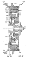
- FIG. 2 depicts a cut-away view of an exemplary embodiment of a hybrid cascading lubrication and cooling system 200 for the electrical machine 102 of FIG. 1 .
- the electrical machine 102 is a nested wound field generator with an outer stage stator 202, a outer stage rotor 204, a rotating rectifier assembly 206, an inner stage stator 208, and an inner stage rotor 210.
- the outer stage rotor 204 and the inner stage rotor 210 are coupled to a rotor member 212, which is driven by the rotation of driveshaft 214.
- the driveshaft 214 rotates about a central axis 216 of the electrical machine 102, causing the rotor member 212 to rotate.
- the outer stage stator 202 and inner stage stator 208 remain stationary as the rotor member 212 rotates.
- the rotating rectifier assembly 206 may be located in close proximity to the outer stage rotor 204 or the inner stage rotor 210 on the rotor member 212, and electrically coupled to both the outer stage rotor 204 and the inner stage rotor 210.
- a wire cover 218 may be used to hold wiring in support of the rotating rectifier assembly 206.
- the rotor member 212 rotates the inner stage rotor 210 in close proximity to the inner stage stator 208, and the outer stage rotor 204 rotates in close proximity to the outer stage stator 202.
- Applying a DC source, such as current from a battery or alternator (not depicted) to the inner stage stator 208 results in a DC field to establish field communication inducing an alternating current in the inner stage rotor 210 as the rotor member 212 rotates.
- the alternating current in the inner stage rotor 210 flows through the rotating rectifier assembly 206 to produce a direct current in the outer stage rotor 204.
- the direct current in the outer stage rotor 204 creates a DC field to establish field communication inducing an alternating current in the outer stage stator 202 as the rotor member 212 rotates.
- the AC in the outer stage stator 202 can be converted to DC via an external output rectifier assembly.
- the electrical machine 102 can convert the mechanical rotation of the driveshaft 214 into a high voltage DC power source.
- the outer stage stator 202, outer stage rotor 204, inner stage stator 208, and inner stage rotor 210 are arranged concentrically about the central axis 216, such that the inner stage stator 208 and the inner stage rotor 210 are radially nested about the central axis 216 of the electrical machine 102 with respect to the outer stage stator 202 and the outer stage rotor 204.
- This configuration results in a minimal impact to the overall length of the driveline system 100 of FIG. 1 when the electrical machine 102 is inserted between the engine 104 and the transmission 106 and attached at coupling points 108.
- the sequence in which nested rotors and stators as nested stages are spaced extending from the driveshaft 214 can vary within the scope of the invention.
- the radial distance between the inner stage rotor 210 and the central axis 216 may be less than the radial distance between the inner stage stator 208 and the central axis 216 as depicted in FIG. 2 .
- the radial distance between the inner stage rotor 210 and the central axis 216 can be greater than the radial distance between the inner stage stator 208 and the central axis 216, for instance, reversing the relative position of the inner stage stator 208 and the inner stage rotor 210 depicted in FIG. 2 .
- the radial distance between the outer stage rotor 204 and the central axis 216 can be less than the radial distance between the outer stage stator 202 and the central axis 216 as depicted in FIG. 2 .
- the radial distance between the outer stage rotor 204 and the central axis 216 may be greater than the radial distance between the outer stage stator 202 and the central axis 216.
- a hybrid cascading lubrication and cooling system 200 is integrated in the electrical machine 102.
- An oil pickup tube 220 draws oil responsive to oil pump 222 from oil sump 224. Oil is drawn up oil pump inlet tube 226 to the oil pump 222 and continues to oil pump outlet tube 228. The oil may flow from the oil pump outlet tube 228 to the ERFA 112 of FIG. 1 via the external tubing 110, where heat is extracted from the oil and the oil is filtered. The cooled and filtered oil returns to the electrical machine 102 for distribution in cooling core 230. Centrifugal pumping action of the rotor member 212 rotating drives the oil throughout the electrical machine 102.
- Various types of pumps such as vane, piston, or centrifugal positive displacement pumps, can be used to implement the oil pump 222.
- internally or externally integrated primary pumps or separate pumps can be used to move oil from the oil sump 224 to the ERFA 112 of FIG. 1 .
- Alternate embodiments of the electrical machine 102 include permanent magnet, induction, and switched reluctance generators and/or motors.
- one or more of the outer stage stator 202, outer stage rotor 204, rotating rectifier assembly 206, inner stage stator 208, and/or inner stage rotor 210 can be eliminated or replaced while still maintaining nested stages of the electrical machine 102.
- the rotor member 212 may enable nesting of two separate permanent magnet generators on the driveshaft 214, where the hybrid cascading lubrication and cooling system 200 provides lubrication and cooling.
- FIG. 3 illustrates a profile view of an exemplary embodiment of integrated tubing in the electrical machine 102.
- two oil pumps 222 can draw oil from the oil sump 224 using oil pickup tube 220 branching to two oil pump inlet tubes 226.
- the oil pumps 222 are positive-displacement pumps that may be driven off of the driveshaft 214 of FIG. 2 via gearing to lift the oil from the oil sump 224, and pump it to the ERFA 112 of FIG. 1 .
- Oil flows from each oil pump 222 to a respective oil pump outlet tube 228 to a port 302, which combines the oil flow for the ERFA 112 of FIG. 1 .
- Oil returning from the ERFA 112 of FIG. 1 is received at the cooling core 230 of FIG. 2 , where it is distributed within the electrical machine 102, eventually returning to the oil sump 224.
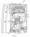
- FIG. 4 illustrates a hybrid cascading lubrication and cooling system 400 for electrical machine 102.
- the hybrid cascading lubrication and cooling system 400 represents a detailed view of an embodiment of the hybrid cascading lubrication and cooling system 200 of FIG. 2 .
- oil enters the electrical machine 102 at port 402 into cooling core 230 for distribution. Oil may be received at the port 402 from the ERFA 112 of FIG. 1 .
- a portion of the oil in the cooling core 230 flows to port 404 to cool a heat exchanger 406 of the electrical machine 102, and the oil then proceeds back to the oil sump 224 of FIGs. 2 and 3 .
- the oil also flows down the cooling core 230 to ports 408 and 410.
- the gear 414 may be used to drive one or more oil pump 222 of FIGs. 2 and 3 .
- the bearings 412 and 418 enable the electrical machine 102 to be self-supporting.
- a crankshaft in the engine 104 of FIG. 1 is directly coupled to the rotor member 212, where the rotor member 212 acts as a flywheel for the engine 104.
- bearings 412 and 418 can be omitted, as crankshaft bearings in the engine 104 may be sufficient to support rotation of the rotor member 212.
- the outer stage stator 202 and the inner stage stator 208 can be directly coupled to the engine 104. Thus, if bearings 412 and 418 are omitted, oil is not sprayed on the bearings 412 and 418. Such an embodiment may also eliminate the centrifugal reservoir 416.
- cooling oil leaves the cooling core 230, and is sprayed into inner stage centrifugal reservoir 420.
- the oil is pressurized by centrifugal pumping action of the rotor member 212 rotating, and oil is directed to flow across windings 422 of the inner stage rotor 210 providing cooling oil flow to the inner stage rotor 210.
- Oil gathers in the inner stage centrifugal reservoir 420 prior to passing through inner radial holes 424 in the circumference of rotor winding retention bands 426 of the rotor member 212. Oil also gathers in inner stage centrifugal reservoir 428 to cool the inner stage rotor 210.
- Oil is sprayed from the inner stage centrifugal reservoir 428 across windings 430 of the inner stage stator 208 to provide a cooling oil flow to the inner stage stator 208.
- the outer stage centrifugal reservoir 432 also receives supplemental cooling oil from the cooling core 230 at port 410.
- Oil at the outer stage centrifugal reservoir 432 is repressurized by centrifugal pumping action of the rotor member 212 rotating, prior to flowing through outer radial holes 436 in the rotor member 212.
- the oil is directed to flow across windings 438 of the outer stage rotor 204, providing cooling oil to the outer stage rotor 204.
- Oil is trapped in the outer stage centrifugal reservoir 434 prior to leaving the outer stage rotor 204 and spraying on windings 440 of the outer stage stator 202. After oil is sprayed on the windings 440, the oil is forced by gravity back to the oil sump 224 of the electrical machine 102, as depicted in FIGs. 2 and 3 .
- the combination of components that enable oil to flow from the oil sump 224 to the ERFA 112 of FIG. 1 and distribute the oil within the electrical machine 102 forms the hybrid cascading lubrication and cooling system 400.
- the ERFA 112 does not need to be included in the hybrid cascading lubrication and cooling system 400.
- Oil distribution within the electrical machine 102 uses the centrifugal pumping action of the rotor member 212 rotating to provide motive force to cause the oil to flow throughout the electrical machine 102.
- Oil delivered to electrical machine core 442 is collected and passed through inner radial holes 424 to inner nested stage 444 of the electrical machine 102.
- Oil in the inner nested stage 444 is centrifugally pumped towards outer nested stage 446, where supplemental oil is added from port 410 prior to passing through outer radial holes 436 to the outer nested stage 446.
- the inner nested stage 444 may include the inner stage stator 208 and the inner stage rotor 210, and the outer nested stage 446 may include the outer stage stator 202 and the outer stage rotor 204.
- the inner nested stage 444 is radially nested about the central axis 216 of the electrical machine 102 with respect to the outer nested stage 446.
- the inner nested stage 444 and the outer nested stage 446 can include other field generating components, such as magnets, rather than using windings. Additionally, the inner nested stage 444 and the outer nested stage 446 can be electrically independent, resulting in separate voltage outputs from the electrical machine 102.
- the flow of oil between the inner stage centrifugal reservoirs 420 and 428 and the outer stage centrifugal reservoirs 432 and 434 acts as cascading cooling shelves as oil moves between centrifugal reservoirs.
- Geometry of the rotor member 212 within the electrical machine 102 forms the inner stage centrifugal reservoir 420 and the outer stage centrifugal reservoir 432, which feed the inner radial holes 424 and outer radial holes 436 to centrifugally transfer oil radially outward.
- the inner radial holes 424 and outer radial holes 436 direct the oil from the inner stage centrifugal reservoir 420 and the outer stage centrifugal reservoir 432 to respective sources of heat for cooling and lubrication.
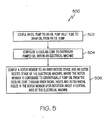
- FIG. 5 depicts a process 500 for producing a hybrid cascading lubrication and cooling system 400 in an electrical machine with nested stages, such as the electrical machine 102 of FIGs. 1-4 .
- the inner nested stage 444 is radially nested about central axis 216 of the electrical machine 102 with respect to the outer nested stage 446.
- the inner nested stage 444 may include inner stage stator 208 and inner stage rotor 210.
- the outer nested stage 446 may include outer stage stator 202 and outer stage rotor 204.
- oil pump 222 is coupled to oil pump inlet tube 226 to draw oil from oil sump 224. Additional oil pumps 222 can also be used depending upon the desired flow rate and sizing constraints. For example, as depicted in FIG. 3 , a second oil pump 222 can be coupled to a second oil pump inlet tube 226 to draw oil from the oil sump 224. The second oil pump outlet tube 228 may be coupled to the second oil pump 222. Port 302 of FIG. 3 can be coupled to the oil pump outlet tube 228 and the second oil pump outlet tube 228 to combine oil flow from the oil pump 222 and the second oil pump 222 prior to routing the oil flow to the ERFA 112 of FIG. 1 . The cooling core 230 may receive oil returned from the ERFA 112.
- cooling core 230 is configured to distribute pumped oil within the electrical machine 102.
- Oil can be directed through port 404 coupled to the cooling core 230 to cool the heat exchanger 406 of the electrical machine 102.
- Oil can also be directed through port 408 coupled to the cooling core 230 to cool and lubricate bearing 412 and gear 414 of the electrical machine 102.
- Port 408 may supply oil to centrifugal reservoir 416, which in turn supplies bearing 418 with oil.
- Port 408 can also supply oil to inner stage centrifugal reservoir 420 of the inner nested stage 444.
- Port 410 may also be coupled to the cooling core 230, where port 410 provides a flow path to combine supplemental oil with oil from the inner nested stage 444 at outer stage centrifugal reservoir 432 of the outer nested stage 446.
- rotor member 212 is coupled to the inner nested stage 444 and the outer nested stage 446.
- the rotor member 212 can be coupled to the inner stage rotor 210 and the outer stage rotor 204.
- the rotor member 212 is configured to centrifugally pump oil from the cooling core 230 through inner radial holes 424 and outer radial holes 436 in the rotor member 212 upon rotation about the central axis 216 of the electrical machine 102.
- the inner radial holes 424 provide a flow path for oil from the inner stage centrifugal reservoir 420 through the inner nested stage 444, which can cool and lubricate the inner stage stator 208 and the inner stage rotor 210.
- the outer radial holes 436 provide a flow path for oil from the outer stage centrifugal reservoir 432 through the outer nested stage 446, which can cool and lubricate the outer stage stator 202 and the outer stage rotor 204.
- the rotation of the rotor member 212 provides centrifugal pumping force to cascade oil from electrical machine core 442 to inner nested stage 444 to outer nested stage 446.
- the hybrid cascading lubrication and cooling system 400 produced via process 500 of FIG. 5 is integrated in electrical machine 102.
- the electrical machine 102 can be connected inline on driveline system 100 via coupling points 108, for instance, to couple the electrical machine 102 to engine 104 and transmission 106 of FIG. 1 .
- the engine 104, electrical machine 102, and transmission 106 may be driven by driveshaft 214 of FIG. 2 .
- Various arrangements of the inner stage rotor 210, inner stage stator 208, outer stage rotor 204, and outer stage stator 202 can be used to place components closer or further from the central axis 216. Keeping components with a higher mass closer to the central axis 216 may affect the moment of inertia and other design/performance parameters of the electrical machine 102.
- Technical effects include providing cooling and lubrication for a driveline installable electrical machine with nested stages.
- the nested design of the inner and outer stages of the electrical machine when used with the centrifugal reservoir geometry illustrated in FIGs. 2 and 4 , enables a high energy density electrical machine to be packaged with a shorter axial length.
- the combined use of positive displacement pumps to provide suction with centrifugal pumping action of nested stages creates a hybrid cascading lubrication and cooling system with high reliability to lubricate and cool an electrical machine.
Landscapes
- Engineering & Computer Science (AREA)
- Power Engineering (AREA)
- Transportation (AREA)
- Mechanical Engineering (AREA)
- Chemical & Material Sciences (AREA)
- Combustion & Propulsion (AREA)
- Motor Or Generator Cooling System (AREA)
- Motor Or Generator Frames (AREA)
Abstract
Description
- The subject matter disclosed herein generally relates to lubrication and cooling of electrical machines, and more particularly to hybrid cascading lubrication and cooling for an electrical machine with nested stages.
- An electrical machine may include one or more stages arranged sequentially along a shaft as a rotor assembly. To cool the electrical machine, cooling oil can be pumped into the inside diameter of the shaft. The cooling oil flows through the rotor assembly to remove heat. The cooling oil can be pressurized and sprayed directly from the shaft to cool components in close physical proximity to the shaft. However, such a cooling and lubrication scheme may be ineffective if cooling oil cannot be pumped through the shaft or components to be cooled are not directly reachable by spray from the shaft.
- According to one aspect of the invention, a hybrid cascading lubrication and cooling system for an electrical machine with nested stages is provided. The electrical machine includes an inner nested stage and an outer nested stage, where the inner nested stage is radially nested about a central axis of the electrical machine with respect to the outer nested stage. The hybrid cascading lubrication and cooling system includes an oil pump coupled to an oil pump inlet tube to draw oil from an oil sump, and a cooling core to distribute pumped oil within the electrical machine. A rotor member is coupled to the inner nested stage and the outer nested stage of the electrical machine. The rotor member centrifugally pumps oil from the cooling core through inner radial holes and outer radial holes in the rotor member upon rotation about the central axis of the electrical machine.
- According to yet another aspect of the invention, a method for producing a hybrid cascading lubrication and cooling system for an electrical machine with nested stages is provided. The electrical machine includes an inner nested stage and an outer nested stage, where the inner nested stage is radially nested about a central axis of the electrical machine with respect to the outer nested stage. The method includes coupling an oil pump to an oil pump inlet tube to draw oil from an oil sump, and configuring a cooling core to distribute pumped oil within the electrical machine. The method additionally includes coupling a rotor member to the inner nested stage and the outer nested stage of the electrical machine. The rotor member is configured to centrifugally pump oil from the cooling core through inner radial holes and outer radial holes in the rotor member upon rotation about the central axis of the electrical machine.
- These and other advantages and features will become more apparent from the following description taken in conjunction with the drawings.
- The subject matter which is regarded as the invention is particularly pointed out and distinctly claimed in the claims at the conclusion of the specification. The foregoing and other features, and advantages of the invention are apparent from the following detailed description taken in conjunction with the accompanying drawings in which:
-
FIG. 1 illustrates an exemplary embodiment of a driveline system that includes an electrical machine installed in the driveline system; -
FIG. 2 depicts a cut-away view of an exemplary embodiment of a hybrid cascading lubrication and cooling system for an electrical machine with nested stages; -
FIG. 3 illustrates a profile view of an exemplary embodiment of integrated tubing in an electrical machine; -
FIG. 4 illustrates a cut-away view of an exemplary embodiment of a hybrid cascading lubrication and cooling system for an electrical machine with nested stages; and -
FIG. 5 depicts a process for producing a hybrid cascading lubrication and cooling system for an electrical machine with nested stages. - The detailed description explains embodiments of the invention, together with advantages and features, by way of example with reference to the drawings.
-
FIG. 1 illustrates an exemplary embodiment of adriveline system 100. In an exemplary embodiment, thedriveline system 100 is part of a land-based vehicle driveline, such as a truck or a tank. Thedriveline system 100 includes anelectrical machine 102 inserted between anengine 104 and atransmission 106. In an exemplary embodiment, theelectrical machine 102 hascoupling points 108 that align with existing coupling points on theengine 104 andtransmission 106. Thus, the impact on existing components, such as theengine 104 andtransmission 106, can be minimized when theelectrical machine 102 is inserted into thedriveline system 100. While theelectrical machine 102 is depicted between theengine 104 andtransmission 106, it will be understood that the arrangement of components on thedriveline system 100 is not so limited. For instance, there may be additional components, such as a clutch inserted in thedriveline system 100, or theelectrical machine 102 may be coupled to the opposite end of thetransmission 106 if a smaller diameter is desired for theelectrical machine 102. Theelectrical machine 102 may be a generator or alternator for producing electrical current and voltage responsive to mechanical rotation. - In an exemplary embodiment, the
electrical machine 102 is coupled toexternal tubing 110 to route oil to and from a heat exchanger / relief valve / filter assembly (ERFA) 112. Oil that circulates through theelectrical machine 102 draws heat generated by theelectrical machine 102 and also lubricates components of theelectrical machine 102. The oil in theelectrical machine 102 may also capture particulate matter and other debris from within theelectrical machine 102. One or more pumps circulate the oil through theexternal tubing 110 to the ERFA 112, where the oil is cooled and filtered prior to returning to theelectrical machine 102. -
FIG. 2 depicts a cut-away view of an exemplary embodiment of a hybrid cascading lubrication andcooling system 200 for theelectrical machine 102 ofFIG. 1 . In the exemplary embodiment of theelectrical machine 102 depicted inFIG. 2 , theelectrical machine 102 is a nested wound field generator with anouter stage stator 202, aouter stage rotor 204, a rotatingrectifier assembly 206, aninner stage stator 208, and aninner stage rotor 210. Theouter stage rotor 204 and theinner stage rotor 210 are coupled to arotor member 212, which is driven by the rotation ofdriveshaft 214. In an exemplary embodiment, thedriveshaft 214 rotates about acentral axis 216 of theelectrical machine 102, causing therotor member 212 to rotate. Theouter stage stator 202 andinner stage stator 208 remain stationary as therotor member 212 rotates. The rotatingrectifier assembly 206 may be located in close proximity to theouter stage rotor 204 or theinner stage rotor 210 on therotor member 212, and electrically coupled to both theouter stage rotor 204 and theinner stage rotor 210. Awire cover 218 may be used to hold wiring in support of the rotatingrectifier assembly 206. - As the
driveshaft 214 rotates, therotor member 212 rotates theinner stage rotor 210 in close proximity to theinner stage stator 208, and theouter stage rotor 204 rotates in close proximity to theouter stage stator 202. Applying a DC source, such as current from a battery or alternator (not depicted), to theinner stage stator 208 results in a DC field to establish field communication inducing an alternating current in theinner stage rotor 210 as therotor member 212 rotates. The alternating current in theinner stage rotor 210 flows through the rotatingrectifier assembly 206 to produce a direct current in theouter stage rotor 204. The direct current in theouter stage rotor 204 creates a DC field to establish field communication inducing an alternating current in theouter stage stator 202 as therotor member 212 rotates. The AC in theouter stage stator 202 can be converted to DC via an external output rectifier assembly. Thus, theelectrical machine 102 can convert the mechanical rotation of thedriveshaft 214 into a high voltage DC power source. - As can be seen in
FIG. 2 , theouter stage stator 202,outer stage rotor 204,inner stage stator 208, andinner stage rotor 210 are arranged concentrically about thecentral axis 216, such that theinner stage stator 208 and theinner stage rotor 210 are radially nested about thecentral axis 216 of theelectrical machine 102 with respect to theouter stage stator 202 and theouter stage rotor 204. This configuration results in a minimal impact to the overall length of thedriveline system 100 ofFIG. 1 when theelectrical machine 102 is inserted between theengine 104 and thetransmission 106 and attached atcoupling points 108. - The sequence in which nested rotors and stators as nested stages are spaced extending from the
driveshaft 214 can vary within the scope of the invention. For example, the radial distance between theinner stage rotor 210 and thecentral axis 216 may be less than the radial distance between theinner stage stator 208 and thecentral axis 216 as depicted inFIG. 2 . As an alternate configuration, the radial distance between theinner stage rotor 210 and thecentral axis 216 can be greater than the radial distance between theinner stage stator 208 and thecentral axis 216, for instance, reversing the relative position of theinner stage stator 208 and theinner stage rotor 210 depicted inFIG. 2 . In similar fashion, the radial distance between theouter stage rotor 204 and thecentral axis 216 can be less than the radial distance between theouter stage stator 202 and thecentral axis 216 as depicted inFIG. 2 . Conversely, the radial distance between theouter stage rotor 204 and thecentral axis 216 may be greater than the radial distance between theouter stage stator 202 and thecentral axis 216. - To cool and lubricate components of the
electrical machine 102, a hybrid cascading lubrication andcooling system 200 is integrated in theelectrical machine 102. Anoil pickup tube 220 draws oil responsive tooil pump 222 fromoil sump 224. Oil is drawn up oilpump inlet tube 226 to theoil pump 222 and continues to oilpump outlet tube 228. The oil may flow from the oilpump outlet tube 228 to the ERFA 112 ofFIG. 1 via theexternal tubing 110, where heat is extracted from the oil and the oil is filtered. The cooled and filtered oil returns to theelectrical machine 102 for distribution incooling core 230. Centrifugal pumping action of therotor member 212 rotating drives the oil throughout theelectrical machine 102. While only asingle oil pump 222 is depicted inFIG. 2 , multiple instances of theoil pump 222 can be utilized for redundancy and to keep the size of eachoil pump 222 compact. Various types of pumps, such as vane, piston, or centrifugal positive displacement pumps, can be used to implement theoil pump 222. Furthermore, internally or externally integrated primary pumps or separate pumps can be used to move oil from theoil sump 224 to theERFA 112 ofFIG. 1 . - Alternate embodiments of the
electrical machine 102 include permanent magnet, induction, and switched reluctance generators and/or motors. In these alternate embodiments, one or more of theouter stage stator 202,outer stage rotor 204, rotatingrectifier assembly 206,inner stage stator 208, and/orinner stage rotor 210 can be eliminated or replaced while still maintaining nested stages of theelectrical machine 102. For example, therotor member 212 may enable nesting of two separate permanent magnet generators on thedriveshaft 214, where the hybrid cascading lubrication andcooling system 200 provides lubrication and cooling. -
FIG. 3 illustrates a profile view of an exemplary embodiment of integrated tubing in theelectrical machine 102. As can be seen inFIG. 3 , twooil pumps 222 can draw oil from theoil sump 224 usingoil pickup tube 220 branching to two oilpump inlet tubes 226. The oil pumps 222 are positive-displacement pumps that may be driven off of thedriveshaft 214 ofFIG. 2 via gearing to lift the oil from theoil sump 224, and pump it to theERFA 112 ofFIG. 1 . Oil flows from eachoil pump 222 to a respective oilpump outlet tube 228 to aport 302, which combines the oil flow for theERFA 112 ofFIG. 1 . Oil returning from theERFA 112 ofFIG. 1 is received at thecooling core 230 ofFIG. 2 , where it is distributed within theelectrical machine 102, eventually returning to theoil sump 224. -
FIG. 4 illustrates a hybrid cascading lubrication andcooling system 400 forelectrical machine 102. The hybrid cascading lubrication andcooling system 400 represents a detailed view of an embodiment of the hybrid cascading lubrication andcooling system 200 ofFIG. 2 . As is illustrated inFIG. 4 , oil enters theelectrical machine 102 atport 402 intocooling core 230 for distribution. Oil may be received at theport 402 from theERFA 112 ofFIG. 1 . A portion of the oil in thecooling core 230 flows toport 404 to cool aheat exchanger 406 of theelectrical machine 102, and the oil then proceeds back to theoil sump 224 ofFIGs. 2 and3 . The oil also flows down thecooling core 230 toports port 408, oil exits thecooling core 230 and is sprayed onto bearing 412,gear 414, and intocentrifugal reservoir 416 that supplies bearing 418 with oil. Thegear 414 may be used to drive one ormore oil pump 222 ofFIGs. 2 and3 . - The
bearings electrical machine 102 to be self-supporting. In an alternate embodiment, a crankshaft in theengine 104 ofFIG. 1 is directly coupled to therotor member 212, where therotor member 212 acts as a flywheel for theengine 104. In this embodiment,bearings engine 104 may be sufficient to support rotation of therotor member 212. Theouter stage stator 202 and theinner stage stator 208 can be directly coupled to theengine 104. Thus, ifbearings bearings centrifugal reservoir 416. - At
port 408, cooling oil leaves thecooling core 230, and is sprayed into inner stagecentrifugal reservoir 420. In the inner stagecentrifugal reservoir 420, the oil is pressurized by centrifugal pumping action of therotor member 212 rotating, and oil is directed to flow acrosswindings 422 of theinner stage rotor 210 providing cooling oil flow to theinner stage rotor 210. Oil gathers in the inner stagecentrifugal reservoir 420 prior to passing through innerradial holes 424 in the circumference of rotor windingretention bands 426 of therotor member 212. Oil also gathers in inner stagecentrifugal reservoir 428 to cool theinner stage rotor 210. - Oil is sprayed from the inner stage
centrifugal reservoir 428 acrosswindings 430 of theinner stage stator 208 to provide a cooling oil flow to theinner stage stator 208. As the oil leaves theinner stage stator 208, it is collected by outer stagecentrifugal reservoir 432 and outer stagecentrifugal reservoir 434. The outer stagecentrifugal reservoir 432 also receives supplemental cooling oil from thecooling core 230 atport 410. Oil at the outer stagecentrifugal reservoir 432 is repressurized by centrifugal pumping action of therotor member 212 rotating, prior to flowing through outer radial holes 436 in therotor member 212. As oil passes through the outer radial holes 436, the oil is directed to flow acrosswindings 438 of theouter stage rotor 204, providing cooling oil to theouter stage rotor 204. - Oil is trapped in the outer stage
centrifugal reservoir 434 prior to leaving theouter stage rotor 204 and spraying onwindings 440 of theouter stage stator 202. After oil is sprayed on thewindings 440, the oil is forced by gravity back to theoil sump 224 of theelectrical machine 102, as depicted inFIGs. 2 and3 . - The combination of components that enable oil to flow from the
oil sump 224 to theERFA 112 ofFIG. 1 and distribute the oil within theelectrical machine 102 forms the hybrid cascading lubrication andcooling system 400. However, theERFA 112 does not need to be included in the hybrid cascading lubrication andcooling system 400. Oil distribution within theelectrical machine 102 uses the centrifugal pumping action of therotor member 212 rotating to provide motive force to cause the oil to flow throughout theelectrical machine 102. Oil delivered toelectrical machine core 442 is collected and passed through innerradial holes 424 to inner nestedstage 444 of theelectrical machine 102. Oil in the inner nestedstage 444 is centrifugally pumped towards outer nestedstage 446, where supplemental oil is added fromport 410 prior to passing through outer radial holes 436 to the outer nestedstage 446. The inner nestedstage 444 may include theinner stage stator 208 and theinner stage rotor 210, and the outer nestedstage 446 may include theouter stage stator 202 and theouter stage rotor 204. The inner nestedstage 444 is radially nested about thecentral axis 216 of theelectrical machine 102 with respect to the outer nestedstage 446. In alternate embodiments, the inner nestedstage 444 and the outer nestedstage 446 can include other field generating components, such as magnets, rather than using windings. Additionally, the inner nestedstage 444 and the outer nestedstage 446 can be electrically independent, resulting in separate voltage outputs from theelectrical machine 102. - The flow of oil between the inner stage
centrifugal reservoirs centrifugal reservoirs rotor member 212 within theelectrical machine 102 forms the inner stagecentrifugal reservoir 420 and the outer stagecentrifugal reservoir 432, which feed the innerradial holes 424 and outer radial holes 436 to centrifugally transfer oil radially outward. The innerradial holes 424 and outer radial holes 436 direct the oil from the inner stagecentrifugal reservoir 420 and the outer stagecentrifugal reservoir 432 to respective sources of heat for cooling and lubrication. -
FIG. 5 depicts aprocess 500 for producing a hybrid cascading lubrication andcooling system 400 in an electrical machine with nested stages, such as theelectrical machine 102 ofFIGs. 1-4 . As previously described, the inner nestedstage 444 is radially nested aboutcentral axis 216 of theelectrical machine 102 with respect to the outer nestedstage 446. The inner nestedstage 444 may includeinner stage stator 208 andinner stage rotor 210. The outer nestedstage 446 may includeouter stage stator 202 andouter stage rotor 204. - At
block 502,oil pump 222 is coupled to oilpump inlet tube 226 to draw oil fromoil sump 224. Additional oil pumps 222 can also be used depending upon the desired flow rate and sizing constraints. For example, as depicted inFIG. 3 , asecond oil pump 222 can be coupled to a second oilpump inlet tube 226 to draw oil from theoil sump 224. The second oilpump outlet tube 228 may be coupled to thesecond oil pump 222.Port 302 ofFIG. 3 can be coupled to the oilpump outlet tube 228 and the second oilpump outlet tube 228 to combine oil flow from theoil pump 222 and thesecond oil pump 222 prior to routing the oil flow to theERFA 112 ofFIG. 1 . Thecooling core 230 may receive oil returned from theERFA 112. - At
block 504, coolingcore 230 is configured to distribute pumped oil within theelectrical machine 102. Oil can be directed throughport 404 coupled to thecooling core 230 to cool theheat exchanger 406 of theelectrical machine 102. Oil can also be directed throughport 408 coupled to thecooling core 230 to cool and lubricate bearing 412 andgear 414 of theelectrical machine 102.Port 408 may supply oil tocentrifugal reservoir 416, which in turn supplies bearing 418 with oil.Port 408 can also supply oil to inner stagecentrifugal reservoir 420 of the inner nestedstage 444.Port 410 may also be coupled to thecooling core 230, whereport 410 provides a flow path to combine supplemental oil with oil from the inner nestedstage 444 at outer stagecentrifugal reservoir 432 of the outer nestedstage 446. - At
block 506,rotor member 212 is coupled to the inner nestedstage 444 and the outer nestedstage 446. For example, therotor member 212 can be coupled to theinner stage rotor 210 and theouter stage rotor 204. Therotor member 212 is configured to centrifugally pump oil from thecooling core 230 through innerradial holes 424 and outer radial holes 436 in therotor member 212 upon rotation about thecentral axis 216 of theelectrical machine 102. The innerradial holes 424 provide a flow path for oil from the inner stagecentrifugal reservoir 420 through the inner nestedstage 444, which can cool and lubricate theinner stage stator 208 and theinner stage rotor 210. The outer radial holes 436 provide a flow path for oil from the outer stagecentrifugal reservoir 432 through the outer nestedstage 446, which can cool and lubricate theouter stage stator 202 and theouter stage rotor 204. The rotation of therotor member 212 provides centrifugal pumping force to cascade oil fromelectrical machine core 442 to inner nestedstage 444 to outer nestedstage 446. - As described herein, the hybrid cascading lubrication and
cooling system 400 produced viaprocess 500 ofFIG. 5 is integrated inelectrical machine 102. Theelectrical machine 102 can be connected inline ondriveline system 100 via coupling points 108, for instance, to couple theelectrical machine 102 toengine 104 andtransmission 106 ofFIG. 1 . Theengine 104,electrical machine 102, andtransmission 106 may be driven bydriveshaft 214 ofFIG. 2 . Various arrangements of theinner stage rotor 210,inner stage stator 208,outer stage rotor 204, andouter stage stator 202 can be used to place components closer or further from thecentral axis 216. Keeping components with a higher mass closer to thecentral axis 216 may affect the moment of inertia and other design/performance parameters of theelectrical machine 102. - Technical effects include providing cooling and lubrication for a driveline installable electrical machine with nested stages. The nested design of the inner and outer stages of the electrical machine, when used with the centrifugal reservoir geometry illustrated in
FIGs. 2 and4 , enables a high energy density electrical machine to be packaged with a shorter axial length. The combined use of positive displacement pumps to provide suction with centrifugal pumping action of nested stages creates a hybrid cascading lubrication and cooling system with high reliability to lubricate and cool an electrical machine. - While the invention has been described in detail in connection with only a limited number of embodiments, it should be readily understood that the invention is not limited to such disclosed embodiments. Rather, the invention can be modified to incorporate any number of variations, alterations, substitutions or equivalent arrangements not heretofore described, but which are commensurate with the scope of the invention. Additionally, while various embodiments of the invention have been described, it is to be understood that aspects of the invention may include only some of the described embodiments. Accordingly, the invention is not to be seen as limited by the foregoing description, but is only limited by the scope of the appended claims.
Claims (15)
- A hybrid cascading lubrication and cooling system (200, 400) for an electrical machine (102), the electrical machine (102) comprising an inner nested stage (444) and an outer nested stage (446), wherein the inner nested stage (444) is radially nested about a central axis (216) of the electrical machine (102) with respect to the outer nested stage (446), the hybrid cascading lubrication and cooling system (200, 400) comprising:an oil pump (222) coupled to an oil pump inlet tube (226) to draw oil from an oil sump (224);a cooling core (230) configured to distribute pumped oil within the electrical machine (102); anda rotor member (212) coupled to the inner nested stage (444) and the outer nested stage (446) of the electrical machine (102), rotor member (212) configured to centrifugally pump oil from the cooling core (230) through inner radial holes (424) and outer radial holes (436) in the rotor member (212) upon rotation about the central axis (216) of the electrical machine (102).
- The hybrid cascading lubrication and cooling system (200, 400) of claim 1 further comprising a port (404) coupled to the cooling core (230) directing oil to a heat exchanger (406) of the electrical machine (102).
- The hybrid cascading lubrication and cooling system (200, 400) of claim 1 or 2 further comprising a port (408) coupled to the cooling core (230) directing oil to a first bearing (412) and a gear (414) of the electrical machine (102).
- The hybrid cascading lubrication and cooling system (200, 400) of claim 3 wherein the port (408) supplies oil to a centrifugal reservoir (416), and the centrifugal reservoir (416) supplies a second bearing (418) with oil.
- The hybrid cascading lubrication and cooling system (200, 400) of claim 3 or 4 wherein the port (408) supplies oil to an inner stage centrifugal reservoir (420) of the inner nested stage (444).
- The hybrid cascading lubrication and cooling system (200, 400) of claim 5 wherein the inner radial holes (424) provide a flow path for oil from the inner stage centrifugal reservoir (420) through the inner nested stage (444).
- The hybrid cascading lubrication and cooling system (200, 400) of any preceding claim further comprising a port (410) coupled to the cooling core (230), wherein the port (410) provides a flow path to combine supplemental oil with oil from the inner nested stage (444) at an outer stage centrifugal reservoir (432) of the outer nested stage (446); preferably
wherein the outer radial holes (436) provide a flow path for oil from the outer stage centrifugal reservoir (432) through the outer nested stage (446). - The hybrid cascading lubrication and cooling system (200, 400) of any preceding claim further comprising an oil pump outlet tube (228) to route oil flow from the oil pump (222) to a heat exchanger / relief valve / filter assembly (ERFA) (112), wherein the cooling core (230) receives oil returned from the ERFA (112); preferably further comprising:a second oil pump (222) coupled to a second oil pump inlet tube (226) to draw oil from the oil sump (224);a second oil pump outlet tube (228) coupled to a second oil pump (222); anda port (302) to combine oil flow from the oil pump outlet tube (228) and the second oil pump outlet tube (228) prior to the ERFA (112).
- A method for producing a hybrid cascading lubrication and cooling system (200, 400) for an electrical machine (102), the electrical machine (102) comprising an inner nested stage (444) and an outer nested stage (446), wherein the inner nested stage (444) is radially nested about a central axis (216) of the electrical machine (102) with respect to the outer nested stage (446), the method comprising:coupling an oil pump (222) to an oil pump inlet tube (226) to draw oil from an oil sump (224);configuring a cooling core (230) to distribute pumped oil within the electrical machine (102); andcoupling a rotor member (212) to the inner nested stage (444) and the outer nested stage (446) of the electrical machine (102), the rotor member (212) configured to centrifugally pump oil from the cooling core (230) through inner radial holes (424) and outer radial holes (436) in the rotor member (212) upon rotation about the central axis (216) of the electrical machine (102).
- The method of claim 9 further comprising directing oil through a port (404) coupled to the cooling core (230) to a heat exchanger (406) of the electrical machine (102).
- The method of claim 9 or 10 further comprising directing oil through a port (408) coupled to the cooling core (230) to a first bearing (412) and a gear (414) of the electrical machine (102).
- The method of claim 11 wherein the port (408) supplies oil to a centrifugal reservoir (416), and the centrifugal reservoir (416) supplies a second bearing (418) with oil.
- The method of claim 11 or 12 wherein the port (408) supplies oil to an inner stage centrifugal reservoir (420) of the inner nested stage (444); preferably
wherein the inner radial holes (424) provide a flow path for oil from the inner stage centrifugal reservoir (420) through the inner nested stage (444). - The method of claim 9, 10, 11, 12 or 13 further comprising coupling a port (410) to the cooling core (230), wherein the port (410) provides a flow path to combine supplemental oil with oil from the inner nested stage (444) at an outer stage centrifugal reservoir (432) of the outer nested stage (446); preferably
wherein the outer radial holes (436) provide a flow path for oil from the outer stage centrifugal reservoir (432) through the outer nested stage (446). - The method of any of claims 9 to 14 further comprising coupling an oil pump outlet tube (228) to the oil pump (222) to route oil flow to a heat exchanger / relief valve / filter assembly (ERFA) (112), wherein the cooling core (230) receives oil returned from the ERFA (112); preferably further comprising:coupling a second oil pump (222) to a second oil pump inlet tube (226) to draw oil from the oil sump (224);coupling a second oil pump outlet tube (228) to a second oil pump (222); andcoupling a port (302) to the oil pump outlet tube (228) and the second oil pump outlet tube (228) to combine oil flow from the oil pump (222) and the second oil pump (222) prior to routing the oil flow to the ERFA (112).
Applications Claiming Priority (1)
| Application Number | Priority Date | Filing Date | Title |
|---|---|---|---|
| US12/502,492 US8207644B2 (en) | 2009-07-14 | 2009-07-14 | Hybrid cascading lubrication and cooling system |
Publications (3)
| Publication Number | Publication Date |
|---|---|
| EP2276151A2 true EP2276151A2 (en) | 2011-01-19 |
| EP2276151A3 EP2276151A3 (en) | 2015-07-01 |
| EP2276151B1 EP2276151B1 (en) | 2020-07-01 |
Family
ID=42647472
Family Applications (1)
| Application Number | Title | Priority Date | Filing Date |
|---|---|---|---|
| EP10251262.1A Active EP2276151B1 (en) | 2009-07-14 | 2010-07-14 | Hybrid cascading lubrication and cooling system |
Country Status (7)
| Country | Link |
|---|---|
| US (2) | US8207644B2 (en) |
| EP (1) | EP2276151B1 (en) |
| JP (1) | JP5048812B2 (en) |
| KR (1) | KR101156922B1 (en) |
| CN (1) | CN101958609A (en) |
| IL (1) | IL207003A (en) |
| ZA (1) | ZA201005000B (en) |
Cited By (2)
| Publication number | Priority date | Publication date | Assignee | Title |
|---|---|---|---|---|
| GB2516262A (en) * | 2013-07-17 | 2015-01-21 | Daimler Ag | Cover element for a rotor carrier of an electric machine |
| FR3015144A1 (en) * | 2013-12-16 | 2015-06-19 | Hispano Suiza Sa | METHOD FOR COOLING AN ELECTRIC GENERATOR AND DEVICE FOR CARRYING OUT SAID METHOD |
Families Citing this family (22)
| Publication number | Priority date | Publication date | Assignee | Title |
|---|---|---|---|---|
| JP2010541519A (en) | 2007-07-09 | 2010-12-24 | クリアウォーター ホールディングス,リミテッド | Electromagnetic equipment with independent removable coils, module parts and autonomous passive magnetic bearings |
| WO2010036221A1 (en) | 2008-09-26 | 2010-04-01 | Clearwater Holdings, Ltd. | Permanent magnet operating machine |
| US8742641B2 (en) * | 2010-11-23 | 2014-06-03 | Remy Technologies, L.L.C. | Concentric motor power generation and drive system |
| EP2720352B1 (en) * | 2011-06-07 | 2019-08-07 | Honda Motor Co., Ltd. | Drive device for vehicle |
| US20130025833A1 (en) * | 2011-07-29 | 2013-01-31 | Legros Craig R | Static dissipating agent dispersion apparatus and method |
| US9559569B2 (en) | 2012-02-13 | 2017-01-31 | Ge Aviation Systems Llc | Arrangement for cooling an electric machine with a layer of thermally conducting and electrically insulating material |
| US10505412B2 (en) | 2013-01-24 | 2019-12-10 | Clearwater Holdings, Ltd. | Flux machine |
| DE102014208633A1 (en) * | 2014-05-08 | 2015-11-12 | Zf Friedrichshafen Ag | Assembly for a motor vehicle with an electric machine and a clutch actuator |
| KR102540373B1 (en) | 2014-07-23 | 2023-06-05 | 클리어워터 홀딩스, 엘티디. | Flux machine |
| JP6379977B2 (en) * | 2014-10-15 | 2018-08-29 | 日産自動車株式会社 | Cooling structure of rotating electric machine |
| US10273876B2 (en) | 2015-06-08 | 2019-04-30 | Kohler Co. | Dual axis alternator |
| CN106505812A (en) * | 2015-09-08 | 2017-03-15 | 博格华纳公司 | Nested type bi-motor/electromotor |
| DE102015219095A1 (en) * | 2015-10-02 | 2017-04-06 | Robert Bosch Gmbh | Drive unit and unit with cooling |
| US10516320B2 (en) * | 2016-05-09 | 2019-12-24 | Borgwarner Inc. | Cooling system for an electric motor |
| US11189434B2 (en) | 2017-09-08 | 2021-11-30 | Clearwater Holdings, Ltd. | Systems and methods for enhancing electrical energy storage |
| CN111344933B (en) | 2017-10-29 | 2023-04-07 | 清水控股有限公司 | Modular electromagnetic machine and methods of use and manufacture thereof |
| JP6988400B2 (en) * | 2017-11-20 | 2022-01-05 | スズキ株式会社 | Generator cooling structure |
| DE102019132942B4 (en) * | 2019-12-04 | 2024-07-25 | Schaeffler Technologies AG & Co. KG | Drive unit and drive arrangement |
| DE102021212205A1 (en) | 2021-10-28 | 2023-05-04 | Mahle International Gmbh | Electrically excited synchronous machine |
| DE102021212204B4 (en) | 2021-10-28 | 2023-09-28 | Mahle International Gmbh | Electrically excited synchronous machine |
| CN114865850B (en) * | 2022-07-07 | 2022-09-09 | 常州市昊升电机股份有限公司 | Cooling device for motor |
| CN117691804A (en) * | 2024-02-04 | 2024-03-12 | 博格华纳汽车零部件(武汉)有限公司 | Power generation device and new energy automobile |
Family Cites Families (49)
| Publication number | Priority date | Publication date | Assignee | Title |
|---|---|---|---|---|
| US765078A (en) * | 1902-12-01 | 1904-07-12 | Paul Jigouzo | Asynchronous motor. |
| US2864016A (en) * | 1955-11-28 | 1958-12-09 | Waltscheff Dimo Dimitroff | Electromagnetic transmission torque converter |
| US3676764A (en) | 1971-01-29 | 1972-07-11 | Kohler Co | Brushless alternating current generator |
| US3701911A (en) * | 1971-05-20 | 1972-10-31 | Skf Ind Trading & Dev | Motor bearing support and cooling means |
| US4221982A (en) | 1978-07-31 | 1980-09-09 | General Motors Corporation | Liquid cooled rectified-alternating current generator |
| US4887020A (en) | 1984-07-23 | 1989-12-12 | U.S. Philips Corporation | Self-compensating brushless alternator |
| US4684873A (en) | 1985-09-25 | 1987-08-04 | Sundstrand Corporation | Hybrid generating system |
| DE19504847B4 (en) | 1994-02-23 | 2006-04-27 | Luk Gs Verwaltungs Kg | Monitoring method for a torque transmission system of a motor vehicle |
| JPH0923615A (en) * | 1995-07-10 | 1997-01-21 | Aqueous Res:Kk | Motor cooler |
| US6191185B1 (en) | 1995-09-18 | 2001-02-20 | Spalding Sports Worldwide, Inc. | UV curable ink containing aluminum trihydroxide for use in pad printing, and method of printing |
| US5783893A (en) * | 1995-10-20 | 1998-07-21 | Newport News Shipbuilding And Dry Dock Company | Multiple stator, single shaft electric machine |
| FR2765042B1 (en) * | 1997-06-19 | 1999-09-10 | Valeo Equip Electr Moteur | ALTERNATOR WITH IMPROVED COOLING MEANS, IN PARTICULAR FOR A MOTOR VEHICLE |
| US6191510B1 (en) | 1997-12-19 | 2001-02-20 | 3M Innovative Properties Company | Internally damped stator, rotor, and transformer and a method of making |
| US6064121A (en) | 1998-02-27 | 2000-05-16 | Hamilton Sundstrand Corporation | Axially compact generator set and refrigeration system employing the same |
| US6465928B1 (en) | 1998-12-23 | 2002-10-15 | Hamilton Sundstrand Corporation | Multi-pole generator rotor and method of making the same |
| US6174254B1 (en) | 1998-12-30 | 2001-01-16 | Hamilton Sundstrand Corporation | Continuously variable transmission with control arrangement and for reducing transmission belt slippage |
| US6332204B1 (en) | 1999-03-31 | 2001-12-18 | International Business Machines Corporation | Recovering and relocating unreliable disk sectors when encountering disk drive read errors |
| JP2000295818A (en) * | 1999-04-01 | 2000-10-20 | Denso Corp | Liquid-cooled rotating machine |
| JP2000350309A (en) * | 1999-06-04 | 2000-12-15 | Denso Corp | Power converting system and driving system in vehicle |
| US6290620B1 (en) | 1999-06-25 | 2001-09-18 | Hamilton Sundstrand Corporation | Continuously variable transmission with control arrangement and method for reducing impact of shock load |
| US6727609B2 (en) | 2001-08-08 | 2004-04-27 | Hamilton Sundstrand Corporation | Cooling of a rotor for a rotary electric machine |
| US6628005B2 (en) | 2001-09-27 | 2003-09-30 | Siemens Westinghouse Power Corporation | Single speed turbine generator for different power system output frequencies in power generation systems and associated methods |
| DE20220455U1 (en) | 2001-11-15 | 2003-09-04 | Karl Heinz Linnig GmbH & Co. KG, 88677 Markdorf | Device for damping torsional vibrations |
| JP4000863B2 (en) | 2002-02-15 | 2007-10-31 | 株式会社デンソー | Vehicle power generation system |
| US20040000820A1 (en) | 2002-06-13 | 2004-01-01 | Cromas Joseph Charles | Automotive generator |
| FR2844856B1 (en) | 2002-09-24 | 2005-12-30 | Valeo Embrayages | FILTER FOR AUTOMATED REPORTING CHANGE TRANSMISSION, CONTINUOUS OR NOT, IN PARTICULAR FOR MOTOR VEHICLE |
| DE10310777A1 (en) * | 2003-03-12 | 2004-09-23 | Wittur Ag | Electrical machine for direct drive of cable winch disc for elevator has coaxial pairs of electrical winding layers and cooperating permanent magnet layers |
| US7400077B2 (en) * | 2004-03-23 | 2008-07-15 | Electric Motor Development, Inc. | Electric motor having multiple armatures |
| US7230363B2 (en) | 2004-03-30 | 2007-06-12 | Honeywell International, Inc. | Low profile generator configuration |
| US7154193B2 (en) | 2004-09-27 | 2006-12-26 | General Electric Company | Electrical machine with double-sided stator |
| JP2006033939A (en) * | 2004-07-13 | 2006-02-02 | Toyota Motor Corp | Driving apparatus and vehicle with the same |
| JP4254658B2 (en) | 2004-08-23 | 2009-04-15 | 株式会社デンソー | In-vehicle power supply system |
| JP4586542B2 (en) | 2005-01-17 | 2010-11-24 | トヨタ自動車株式会社 | Rotating electric machine |
| JP4677806B2 (en) | 2005-03-25 | 2011-04-27 | 株式会社日立製作所 | Generator and power generation system |
| US7511392B2 (en) | 2005-06-17 | 2009-03-31 | Hamilton Sundstrand Corporation | Rotating rectifier module |
| US7586224B2 (en) | 2005-11-16 | 2009-09-08 | Hamilton Sundstrand Corporation | Rotating rectifier assembly |
| US7389712B2 (en) | 2005-11-21 | 2008-06-24 | Hamilton Sundstrand Corporation | Bi-directional two mode input, uni-directional single mode output drive train |
| US7385332B2 (en) | 2006-04-17 | 2008-06-10 | Hamilton Sundstrand Corporation | Permanent magnet dynamoelectric machine with axially displaceable permanent magnet rotor assembly |
| US7268522B1 (en) | 2006-05-20 | 2007-09-11 | Hamilton Sundstrand Corporation | Excitation control for wound field synchronous dynamoelectric machines |
| US7573145B2 (en) | 2006-11-16 | 2009-08-11 | Cummins Power Generation Ip, Inc. | Electric power generation system controlled to reduce perception of operational changes |
| CN101595320B (en) * | 2007-01-29 | 2011-11-30 | 舍弗勒技术两合公司 | Drive train having a wet starting clutch for hybrid applications |
| US7642684B2 (en) | 2007-02-15 | 2010-01-05 | Hamilton Sunstrand Corporation | Nested variable field dynamoelectric machine |
| US7728475B2 (en) | 2007-02-20 | 2010-06-01 | Hamilton Sundstrand Corporation | Thermally operated rotatable component restraint system |
| US7514806B2 (en) | 2007-06-05 | 2009-04-07 | Honeywell International Inc. | Engine start system with quadrature AC excitation |
| KR100969037B1 (en) * | 2007-11-09 | 2010-07-09 | 현대자동차주식회사 | Device and method for cooling motor of HEV |
| US7728477B2 (en) | 2008-01-17 | 2010-06-01 | Honeywell International Inc. | Dual purpose permanent magnet exciter |
| US7915869B2 (en) | 2008-04-01 | 2011-03-29 | Honeywell International Inc. | Single stage starter/generator with rotor quadrature AC excitation |
| US7923874B2 (en) | 2009-06-17 | 2011-04-12 | Hamilton Sundstrand Corporation | Nested torsional damper for an electric machine |
| US20110006545A1 (en) | 2009-07-08 | 2011-01-13 | Hamilton Sundstrand Corporation | Nested exciter and main generator stages for a wound field generator |
-
2009
- 2009-07-14 US US12/502,492 patent/US8207644B2/en active Active
-
2010
- 2010-06-30 KR KR20100062411A patent/KR101156922B1/en not_active IP Right Cessation
- 2010-07-13 JP JP2010158356A patent/JP5048812B2/en active Active
- 2010-07-13 CN CN2010102346650A patent/CN101958609A/en active Pending
- 2010-07-14 ZA ZA2010/05000A patent/ZA201005000B/en unknown
- 2010-07-14 IL IL20700310A patent/IL207003A/en not_active IP Right Cessation
- 2010-07-14 EP EP10251262.1A patent/EP2276151B1/en active Active
-
2012
- 2012-03-29 US US13/434,081 patent/US8381390B2/en active Active
Non-Patent Citations (1)
| Title |
|---|
| None |
Cited By (3)
| Publication number | Priority date | Publication date | Assignee | Title |
|---|---|---|---|---|
| GB2516262A (en) * | 2013-07-17 | 2015-01-21 | Daimler Ag | Cover element for a rotor carrier of an electric machine |
| FR3015144A1 (en) * | 2013-12-16 | 2015-06-19 | Hispano Suiza Sa | METHOD FOR COOLING AN ELECTRIC GENERATOR AND DEVICE FOR CARRYING OUT SAID METHOD |
| WO2015092215A3 (en) * | 2013-12-16 | 2015-11-05 | Hispano-Suiza | Method for cooling an electric generator and device for implementing said method |
Also Published As
| Publication number | Publication date |
|---|---|
| JP2011024411A (en) | 2011-02-03 |
| KR20110006608A (en) | 2011-01-20 |
| KR101156922B1 (en) | 2012-06-21 |
| US20120186063A1 (en) | 2012-07-26 |
| IL207003A (en) | 2013-09-30 |
| EP2276151A3 (en) | 2015-07-01 |
| CN101958609A (en) | 2011-01-26 |
| JP5048812B2 (en) | 2012-10-17 |
| IL207003A0 (en) | 2010-12-30 |
| US8381390B2 (en) | 2013-02-26 |
| US20110012447A1 (en) | 2011-01-20 |
| EP2276151B1 (en) | 2020-07-01 |
| ZA201005000B (en) | 2012-06-27 |
| US8207644B2 (en) | 2012-06-26 |
Similar Documents
| Publication | Publication Date | Title |
|---|---|---|
| EP2276151B1 (en) | Hybrid cascading lubrication and cooling system | |
| US11025114B2 (en) | Rotor for an electric machine | |
| US7834492B2 (en) | Electric machine having a liquid-cooled rotor | |
| US9197115B2 (en) | Electric machine cooling | |
| US9006942B2 (en) | Generator main stator back-iron cooling sleeve | |
| CN103081313B (en) | Cooling structure of generator motor, and generator motor | |
| US11271456B2 (en) | Method and assembly of an electric machine | |
| CN110957859B (en) | Method and apparatus for cooling rotor assembly | |
| CN103053101B (en) | Cooling structure of generator motor, and generator motor | |
| EP1593192A1 (en) | Rotary machine cooling system | |
| CN102906973B (en) | Generator motor cooling structure and generator motor | |
| US20210265886A1 (en) | Rotor assembly and method of cooling | |
| US11211848B2 (en) | Method and assembly of an electric machine | |
| EP2287999A2 (en) | Electric generator driven by combustion engine and having fluid cooling | |
| US11146157B2 (en) | Dual rotor electric machine in an automotive application | |
| Shoykhet | Two phase gap cooling of an electrical machine |
Legal Events
| Date | Code | Title | Description |
|---|---|---|---|
| PUAI | Public reference made under article 153(3) epc to a published international application that has entered the european phase |
Free format text: ORIGINAL CODE: 0009012 |
|
| AK | Designated contracting states |
Kind code of ref document: A2 Designated state(s): AL AT BE BG CH CY CZ DE DK EE ES FI FR GB GR HR HU IE IS IT LI LT LU LV MC MK MT NL NO PL PT RO SE SI SK SM TR |
|
| AX | Request for extension of the european patent |
Extension state: BA ME RS |
|
| PUAL | Search report despatched |
Free format text: ORIGINAL CODE: 0009013 |
|
| AK | Designated contracting states |
Kind code of ref document: A3 Designated state(s): AL AT BE BG CH CY CZ DE DK EE ES FI FR GB GR HR HU IE IS IT LI LT LU LV MC MK MT NL NO PL PT RO SE SI SK SM TR |
|
| AX | Request for extension of the european patent |
Extension state: BA ME RS |
|
| RIC1 | Information provided on ipc code assigned before grant |
Ipc: H02K 16/00 20060101ALN20150528BHEP Ipc: H02K 7/00 20060101ALI20150528BHEP Ipc: B60L 11/14 20060101ALI20150528BHEP Ipc: H02K 19/38 20060101ALN20150528BHEP Ipc: H02K 9/19 20060101AFI20150528BHEP |
|
| 17P | Request for examination filed |
Effective date: 20151230 |
|
| RBV | Designated contracting states (corrected) |
Designated state(s): AL AT BE BG CH CY CZ DE DK EE ES FI FR GB GR HR HU IE IS IT LI LT LU LV MC MK MT NL NO PL PT RO SE SI SK SM TR |
|
| 17Q | First examination report despatched |
Effective date: 20161006 |
|
| STAA | Information on the status of an ep patent application or granted ep patent |
Free format text: STATUS: EXAMINATION IS IN PROGRESS |
|
| RIC1 | Information provided on ipc code assigned before grant |
Ipc: H02K 7/00 20060101ALI20190717BHEP Ipc: H02K 19/38 20060101ALN20190717BHEP Ipc: H02K 16/00 20060101ALN20190717BHEP Ipc: B60L 50/16 20190101ALI20190717BHEP Ipc: H02K 9/19 20060101AFI20190717BHEP |
|
| GRAP | Despatch of communication of intention to grant a patent |
Free format text: ORIGINAL CODE: EPIDOSNIGR1 |
|
| STAA | Information on the status of an ep patent application or granted ep patent |
Free format text: STATUS: GRANT OF PATENT IS INTENDED |
|
| RIC1 | Information provided on ipc code assigned before grant |
Ipc: H02K 19/38 20060101ALN20190828BHEP Ipc: H02K 16/00 20060101ALN20190828BHEP Ipc: B60L 50/16 20190101ALI20190828BHEP Ipc: H02K 7/00 20060101ALI20190828BHEP Ipc: H02K 9/19 20060101AFI20190828BHEP |
|
| INTG | Intention to grant announced |
Effective date: 20190912 |
|
| RIC1 | Information provided on ipc code assigned before grant |
Ipc: H02K 19/38 20060101ALN20190904BHEP Ipc: B60L 50/16 20190101ALI20190904BHEP Ipc: H02K 16/00 20060101ALN20190904BHEP Ipc: H02K 7/00 20060101ALI20190904BHEP Ipc: H02K 9/19 20060101AFI20190904BHEP |
|
| RAP1 | Party data changed (applicant data changed or rights of an application transferred) |
Owner name: HAMILTON SUNDSTRAND CORPORATION |
|
| GRAJ | Information related to disapproval of communication of intention to grant by the applicant or resumption of examination proceedings by the epo deleted |
Free format text: ORIGINAL CODE: EPIDOSDIGR1 |
|
| STAA | Information on the status of an ep patent application or granted ep patent |
Free format text: STATUS: EXAMINATION IS IN PROGRESS |
|
| GRAP | Despatch of communication of intention to grant a patent |
Free format text: ORIGINAL CODE: EPIDOSNIGR1 |
|
| STAA | Information on the status of an ep patent application or granted ep patent |
Free format text: STATUS: GRANT OF PATENT IS INTENDED |
|
| INTC | Intention to grant announced (deleted) | ||
| RIC1 | Information provided on ipc code assigned before grant |
Ipc: H02K 7/00 20060101ALI20200122BHEP Ipc: H02K 9/19 20060101AFI20200122BHEP Ipc: H02K 16/00 20060101ALN20200122BHEP Ipc: B60L 50/16 20190101ALI20200122BHEP Ipc: H02K 19/38 20060101ALN20200122BHEP |
|
| INTG | Intention to grant announced |
Effective date: 20200207 |
|
| GRAS | Grant fee paid |
Free format text: ORIGINAL CODE: EPIDOSNIGR3 |
|
| GRAA | (expected) grant |
Free format text: ORIGINAL CODE: 0009210 |
|
| STAA | Information on the status of an ep patent application or granted ep patent |
Free format text: STATUS: THE PATENT HAS BEEN GRANTED |
|
| AK | Designated contracting states |
Kind code of ref document: B1 Designated state(s): AL AT BE BG CH CY CZ DE DK EE ES FI FR GB GR HR HU IE IS IT LI LT LU LV MC MK MT NL NO PL PT RO SE SI SK SM TR |
|
| REG | Reference to a national code |
Ref country code: GB Ref legal event code: FG4D |
|
| REG | Reference to a national code |
Ref country code: AT Ref legal event code: REF Ref document number: 1287101 Country of ref document: AT Kind code of ref document: T Effective date: 20200715 Ref country code: CH Ref legal event code: EP |
|
| REG | Reference to a national code |
Ref country code: IE Ref legal event code: FG4D |
|
| REG | Reference to a national code |
Ref country code: DE Ref legal event code: R096 Ref document number: 602010064777 Country of ref document: DE |
|
| REG | Reference to a national code |
Ref country code: LT Ref legal event code: MG4D |
|
| PG25 | Lapsed in a contracting state [announced via postgrant information from national office to epo] |
Ref country code: BG Free format text: LAPSE BECAUSE OF FAILURE TO SUBMIT A TRANSLATION OF THE DESCRIPTION OR TO PAY THE FEE WITHIN THE PRESCRIBED TIME-LIMIT Effective date: 20201001 |
|
| REG | Reference to a national code |
Ref country code: NL Ref legal event code: MP Effective date: 20200701 |
|
| REG | Reference to a national code |
Ref country code: AT Ref legal event code: MK05 Ref document number: 1287101 Country of ref document: AT Kind code of ref document: T Effective date: 20200701 |
|
| PG25 | Lapsed in a contracting state [announced via postgrant information from national office to epo] |
Ref country code: LT Free format text: LAPSE BECAUSE OF FAILURE TO SUBMIT A TRANSLATION OF THE DESCRIPTION OR TO PAY THE FEE WITHIN THE PRESCRIBED TIME-LIMIT Effective date: 20200701 Ref country code: ES Free format text: LAPSE BECAUSE OF FAILURE TO SUBMIT A TRANSLATION OF THE DESCRIPTION OR TO PAY THE FEE WITHIN THE PRESCRIBED TIME-LIMIT Effective date: 20200701 Ref country code: SE Free format text: LAPSE BECAUSE OF FAILURE TO SUBMIT A TRANSLATION OF THE DESCRIPTION OR TO PAY THE FEE WITHIN THE PRESCRIBED TIME-LIMIT Effective date: 20200701 Ref country code: PT Free format text: LAPSE BECAUSE OF FAILURE TO SUBMIT A TRANSLATION OF THE DESCRIPTION OR TO PAY THE FEE WITHIN THE PRESCRIBED TIME-LIMIT Effective date: 20201102 Ref country code: HR Free format text: LAPSE BECAUSE OF FAILURE TO SUBMIT A TRANSLATION OF THE DESCRIPTION OR TO PAY THE FEE WITHIN THE PRESCRIBED TIME-LIMIT Effective date: 20200701 Ref country code: AT Free format text: LAPSE BECAUSE OF FAILURE TO SUBMIT A TRANSLATION OF THE DESCRIPTION OR TO PAY THE FEE WITHIN THE PRESCRIBED TIME-LIMIT Effective date: 20200701 Ref country code: GR Free format text: LAPSE BECAUSE OF FAILURE TO SUBMIT A TRANSLATION OF THE DESCRIPTION OR TO PAY THE FEE WITHIN THE PRESCRIBED TIME-LIMIT Effective date: 20201002 Ref country code: NO Free format text: LAPSE BECAUSE OF FAILURE TO SUBMIT A TRANSLATION OF THE DESCRIPTION OR TO PAY THE FEE WITHIN THE PRESCRIBED TIME-LIMIT Effective date: 20201001 Ref country code: FI Free format text: LAPSE BECAUSE OF FAILURE TO SUBMIT A TRANSLATION OF THE DESCRIPTION OR TO PAY THE FEE WITHIN THE PRESCRIBED TIME-LIMIT Effective date: 20200701 Ref country code: CZ Free format text: LAPSE BECAUSE OF FAILURE TO SUBMIT A TRANSLATION OF THE DESCRIPTION OR TO PAY THE FEE WITHIN THE PRESCRIBED TIME-LIMIT Effective date: 20200701 |
|
| PG25 | Lapsed in a contracting state [announced via postgrant information from national office to epo] |
Ref country code: IS Free format text: LAPSE BECAUSE OF FAILURE TO SUBMIT A TRANSLATION OF THE DESCRIPTION OR TO PAY THE FEE WITHIN THE PRESCRIBED TIME-LIMIT Effective date: 20201101 Ref country code: LV Free format text: LAPSE BECAUSE OF FAILURE TO SUBMIT A TRANSLATION OF THE DESCRIPTION OR TO PAY THE FEE WITHIN THE PRESCRIBED TIME-LIMIT Effective date: 20200701 Ref country code: PL Free format text: LAPSE BECAUSE OF FAILURE TO SUBMIT A TRANSLATION OF THE DESCRIPTION OR TO PAY THE FEE WITHIN THE PRESCRIBED TIME-LIMIT Effective date: 20200701 |
|
| REG | Reference to a national code |
Ref country code: CH Ref legal event code: PL |
|
| PG25 | Lapsed in a contracting state [announced via postgrant information from national office to epo] |
Ref country code: MC Free format text: LAPSE BECAUSE OF FAILURE TO SUBMIT A TRANSLATION OF THE DESCRIPTION OR TO PAY THE FEE WITHIN THE PRESCRIBED TIME-LIMIT Effective date: 20200701 Ref country code: NL Free format text: LAPSE BECAUSE OF FAILURE TO SUBMIT A TRANSLATION OF THE DESCRIPTION OR TO PAY THE FEE WITHIN THE PRESCRIBED TIME-LIMIT Effective date: 20200701 |
|
| REG | Reference to a national code |
Ref country code: DE Ref legal event code: R097 Ref document number: 602010064777 Country of ref document: DE |
|
| REG | Reference to a national code |
Ref country code: BE Ref legal event code: MM Effective date: 20200731 |
|
| PG25 | Lapsed in a contracting state [announced via postgrant information from national office to epo] |
Ref country code: CH Free format text: LAPSE BECAUSE OF NON-PAYMENT OF DUE FEES Effective date: 20200731 Ref country code: EE Free format text: LAPSE BECAUSE OF FAILURE TO SUBMIT A TRANSLATION OF THE DESCRIPTION OR TO PAY THE FEE WITHIN THE PRESCRIBED TIME-LIMIT Effective date: 20200701 Ref country code: DK Free format text: LAPSE BECAUSE OF FAILURE TO SUBMIT A TRANSLATION OF THE DESCRIPTION OR TO PAY THE FEE WITHIN THE PRESCRIBED TIME-LIMIT Effective date: 20200701 Ref country code: LI Free format text: LAPSE BECAUSE OF NON-PAYMENT OF DUE FEES Effective date: 20200731 Ref country code: IT Free format text: LAPSE BECAUSE OF FAILURE TO SUBMIT A TRANSLATION OF THE DESCRIPTION OR TO PAY THE FEE WITHIN THE PRESCRIBED TIME-LIMIT Effective date: 20200701 Ref country code: SM Free format text: LAPSE BECAUSE OF FAILURE TO SUBMIT A TRANSLATION OF THE DESCRIPTION OR TO PAY THE FEE WITHIN THE PRESCRIBED TIME-LIMIT Effective date: 20200701 Ref country code: RO Free format text: LAPSE BECAUSE OF FAILURE TO SUBMIT A TRANSLATION OF THE DESCRIPTION OR TO PAY THE FEE WITHIN THE PRESCRIBED TIME-LIMIT Effective date: 20200701 Ref country code: LU Free format text: LAPSE BECAUSE OF NON-PAYMENT OF DUE FEES Effective date: 20200714 |
|
| PLBE | No opposition filed within time limit |
Free format text: ORIGINAL CODE: 0009261 |
|
| STAA | Information on the status of an ep patent application or granted ep patent |
Free format text: STATUS: NO OPPOSITION FILED WITHIN TIME LIMIT |
|
| RAP4 | Party data changed (patent owner data changed or rights of a patent transferred) |
Owner name: HAMILTON SUNDSTRAND CORPORATION |
|
| PG25 | Lapsed in a contracting state [announced via postgrant information from national office to epo] |
Ref country code: BE Free format text: LAPSE BECAUSE OF NON-PAYMENT OF DUE FEES Effective date: 20200731 Ref country code: AL Free format text: LAPSE BECAUSE OF FAILURE TO SUBMIT A TRANSLATION OF THE DESCRIPTION OR TO PAY THE FEE WITHIN THE PRESCRIBED TIME-LIMIT Effective date: 20200701 |
|
| 26N | No opposition filed |
Effective date: 20210406 |
|
| PG25 | Lapsed in a contracting state [announced via postgrant information from national office to epo] |
Ref country code: SK Free format text: LAPSE BECAUSE OF FAILURE TO SUBMIT A TRANSLATION OF THE DESCRIPTION OR TO PAY THE FEE WITHIN THE PRESCRIBED TIME-LIMIT Effective date: 20200701 |
|
| PG25 | Lapsed in a contracting state [announced via postgrant information from national office to epo] |
Ref country code: SI Free format text: LAPSE BECAUSE OF FAILURE TO SUBMIT A TRANSLATION OF THE DESCRIPTION OR TO PAY THE FEE WITHIN THE PRESCRIBED TIME-LIMIT Effective date: 20200701 Ref country code: IE Free format text: LAPSE BECAUSE OF NON-PAYMENT OF DUE FEES Effective date: 20200714 |
|
| PG25 | Lapsed in a contracting state [announced via postgrant information from national office to epo] |
Ref country code: TR Free format text: LAPSE BECAUSE OF FAILURE TO SUBMIT A TRANSLATION OF THE DESCRIPTION OR TO PAY THE FEE WITHIN THE PRESCRIBED TIME-LIMIT Effective date: 20200701 Ref country code: MT Free format text: LAPSE BECAUSE OF FAILURE TO SUBMIT A TRANSLATION OF THE DESCRIPTION OR TO PAY THE FEE WITHIN THE PRESCRIBED TIME-LIMIT Effective date: 20200701 Ref country code: CY Free format text: LAPSE BECAUSE OF FAILURE TO SUBMIT A TRANSLATION OF THE DESCRIPTION OR TO PAY THE FEE WITHIN THE PRESCRIBED TIME-LIMIT Effective date: 20200701 |
|
| PG25 | Lapsed in a contracting state [announced via postgrant information from national office to epo] |
Ref country code: MK Free format text: LAPSE BECAUSE OF FAILURE TO SUBMIT A TRANSLATION OF THE DESCRIPTION OR TO PAY THE FEE WITHIN THE PRESCRIBED TIME-LIMIT Effective date: 20200701 |
|
| P01 | Opt-out of the competence of the unified patent court (upc) registered |
Effective date: 20230522 |
|
| PGFP | Annual fee paid to national office [announced via postgrant information from national office to epo] |
Ref country code: DE Payment date: 20230620 Year of fee payment: 14 |
|
| PGFP | Annual fee paid to national office [announced via postgrant information from national office to epo] |
Ref country code: GB Payment date: 20240620 Year of fee payment: 15 |
|
| PGFP | Annual fee paid to national office [announced via postgrant information from national office to epo] |
Ref country code: FR Payment date: 20240619 Year of fee payment: 15 |