EP2276008A2 - Power state coordination for portable test tools - Google Patents
Power state coordination for portable test tools Download PDFInfo
- Publication number
- EP2276008A2 EP2276008A2 EP10169934A EP10169934A EP2276008A2 EP 2276008 A2 EP2276008 A2 EP 2276008A2 EP 10169934 A EP10169934 A EP 10169934A EP 10169934 A EP10169934 A EP 10169934A EP 2276008 A2 EP2276008 A2 EP 2276008A2
- Authority
- EP
- European Patent Office
- Prior art keywords
- unit
- primary
- power
- state
- primary unit
- Prior art date
- Legal status (The legal status is an assumption and is not a legal conclusion. Google has not performed a legal analysis and makes no representation as to the accuracy of the status listed.)
- Granted
Links
- 238000000034 method Methods 0.000 claims abstract description 15
- 230000001419 dependent effect Effects 0.000 claims abstract description 3
- 230000008859 change Effects 0.000 claims description 11
- 230000007246 mechanism Effects 0.000 abstract description 11
- 230000005540 biological transmission Effects 0.000 description 25
- 238000005259 measurement Methods 0.000 description 17
- 230000006854 communication Effects 0.000 description 16
- 238000004891 communication Methods 0.000 description 12
- 239000004020 conductor Substances 0.000 description 12
- 238000010586 diagram Methods 0.000 description 8
- 230000008569 process Effects 0.000 description 7
- 230000008878 coupling Effects 0.000 description 4
- 238000010168 coupling process Methods 0.000 description 4
- 238000005859 coupling reaction Methods 0.000 description 4
- 230000009471 action Effects 0.000 description 3
- 239000012528 membrane Substances 0.000 description 3
- IJGRMHOSHXDMSA-UHFFFAOYSA-N Atomic nitrogen Chemical compound N#N IJGRMHOSHXDMSA-UHFFFAOYSA-N 0.000 description 2
- CURLTUGMZLYLDI-UHFFFAOYSA-N Carbon dioxide Chemical compound O=C=O CURLTUGMZLYLDI-UHFFFAOYSA-N 0.000 description 2
- 230000000737 periodic effect Effects 0.000 description 2
- 230000001681 protective effect Effects 0.000 description 2
- 230000001960 triggered effect Effects 0.000 description 2
- 238000004148 unit process Methods 0.000 description 2
- UGFAIRIUMAVXCW-UHFFFAOYSA-N Carbon monoxide Chemical compound [O+]#[C-] UGFAIRIUMAVXCW-UHFFFAOYSA-N 0.000 description 1
- 229910019142 PO4 Inorganic materials 0.000 description 1
- XAGFODPZIPBFFR-UHFFFAOYSA-N aluminium Chemical compound [Al] XAGFODPZIPBFFR-UHFFFAOYSA-N 0.000 description 1
- 229910052782 aluminium Inorganic materials 0.000 description 1
- QVGXLLKOCUKJST-UHFFFAOYSA-N atomic oxygen Chemical compound [O] QVGXLLKOCUKJST-UHFFFAOYSA-N 0.000 description 1
- 229910002092 carbon dioxide Inorganic materials 0.000 description 1
- 239000001569 carbon dioxide Substances 0.000 description 1
- 229910002091 carbon monoxide Inorganic materials 0.000 description 1
- 230000007613 environmental effect Effects 0.000 description 1
- 230000008676 import Effects 0.000 description 1
- 238000007726 management method Methods 0.000 description 1
- 238000012986 modification Methods 0.000 description 1
- 230000004048 modification Effects 0.000 description 1
- 229910052757 nitrogen Inorganic materials 0.000 description 1
- 229910052760 oxygen Inorganic materials 0.000 description 1
- 239000001301 oxygen Substances 0.000 description 1
- NBIIXXVUZAFLBC-UHFFFAOYSA-K phosphate Chemical compound [O-]P([O-])([O-])=O NBIIXXVUZAFLBC-UHFFFAOYSA-K 0.000 description 1
- 239000010452 phosphate Substances 0.000 description 1
- 230000004044 response Effects 0.000 description 1
- 230000035945 sensitivity Effects 0.000 description 1
- 239000000126 substance Substances 0.000 description 1
- 239000002351 wastewater Substances 0.000 description 1
Images


Classifications
-
- G—PHYSICS
- G05—CONTROLLING; REGULATING
- G05F—SYSTEMS FOR REGULATING ELECTRIC OR MAGNETIC VARIABLES
- G05F1/00—Automatic systems in which deviations of an electric quantity from one or more predetermined values are detected at the output of the system and fed back to a device within the system to restore the detected quantity to its predetermined value or values, i.e. retroactive systems
- G05F1/66—Regulating electric power
-
- G—PHYSICS
- G01—MEASURING; TESTING
- G01R—MEASURING ELECTRIC VARIABLES; MEASURING MAGNETIC VARIABLES
- G01R1/00—Details of instruments or arrangements of the types included in groups G01R5/00 - G01R13/00 and G01R31/00
- G01R1/02—General constructional details
-
- G—PHYSICS
- G01—MEASURING; TESTING
- G01R—MEASURING ELECTRIC VARIABLES; MEASURING MAGNETIC VARIABLES
- G01R22/00—Arrangements for measuring time integral of electric power or current, e.g. electricity meters
- G01R22/06—Arrangements for measuring time integral of electric power or current, e.g. electricity meters by electronic methods
- G01R22/061—Details of electronic electricity meters
- G01R22/065—Details of electronic electricity meters related to mechanical aspects
-
- G—PHYSICS
- G05—CONTROLLING; REGULATING
- G05B—CONTROL OR REGULATING SYSTEMS IN GENERAL; FUNCTIONAL ELEMENTS OF SUCH SYSTEMS; MONITORING OR TESTING ARRANGEMENTS FOR SUCH SYSTEMS OR ELEMENTS
- G05B15/00—Systems controlled by a computer
- G05B15/02—Systems controlled by a computer electric
-
- G—PHYSICS
- G08—SIGNALLING
- G08C—TRANSMISSION SYSTEMS FOR MEASURED VALUES, CONTROL OR SIMILAR SIGNALS
- G08C17/00—Arrangements for transmitting signals characterised by the use of a wireless electrical link
- G08C17/02—Arrangements for transmitting signals characterised by the use of a wireless electrical link using a radio link
-
- G—PHYSICS
- G08—SIGNALLING
- G08C—TRANSMISSION SYSTEMS FOR MEASURED VALUES, CONTROL OR SIMILAR SIGNALS
- G08C17/00—Arrangements for transmitting signals characterised by the use of a wireless electrical link
- G08C17/04—Arrangements for transmitting signals characterised by the use of a wireless electrical link using magnetically coupled devices
-
- G—PHYSICS
- G08—SIGNALLING
- G08C—TRANSMISSION SYSTEMS FOR MEASURED VALUES, CONTROL OR SIMILAR SIGNALS
- G08C23/00—Non-electrical signal transmission systems, e.g. optical systems
- G08C23/04—Non-electrical signal transmission systems, e.g. optical systems using light waves, e.g. infrared
-
- H—ELECTRICITY
- H04—ELECTRIC COMMUNICATION TECHNIQUE
- H04Q—SELECTING
- H04Q9/00—Arrangements in telecontrol or telemetry systems for selectively calling a substation from a main station, in which substation desired apparatus is selected for applying a control signal thereto or for obtaining measured values therefrom
-
- G—PHYSICS
- G01—MEASURING; TESTING
- G01R—MEASURING ELECTRIC VARIABLES; MEASURING MAGNETIC VARIABLES
- G01R15/00—Details of measuring arrangements of the types provided for in groups G01R17/00 - G01R29/00, G01R33/00 - G01R33/26 or G01R35/00
- G01R15/12—Circuits for multi-testers, i.e. multimeters, e.g. for measuring voltage, current, or impedance at will
-
- H—ELECTRICITY
- H04—ELECTRIC COMMUNICATION TECHNIQUE
- H04Q—SELECTING
- H04Q2209/00—Arrangements in telecontrol or telemetry systems
- H04Q2209/40—Arrangements in telecontrol or telemetry systems using a wireless architecture
-
- H—ELECTRICITY
- H04—ELECTRIC COMMUNICATION TECHNIQUE
- H04Q—SELECTING
- H04Q2209/00—Arrangements in telecontrol or telemetry systems
- H04Q2209/80—Arrangements in the sub-station, i.e. sensing device
- H04Q2209/88—Providing power supply at the sub-station
-
- H—ELECTRICITY
- H04—ELECTRIC COMMUNICATION TECHNIQUE
- H04Q—SELECTING
- H04Q2209/00—Arrangements in telecontrol or telemetry systems
- H04Q2209/80—Arrangements in the sub-station, i.e. sensing device
- H04Q2209/88—Providing power supply at the sub-station
- H04Q2209/883—Providing power supply at the sub-station where the sensing device enters an active or inactive mode
Definitions
- the present disclosure relates to coordinating power states of two or more detachable and re-attachable components of portable measurement tools.
- Measurement tools are often used in dangerous environments.
- a user of a measurement tool may be required to wear cumbersome personal protective gear for safety reasons, thus making it awkward, for example, to view the display of a measurement tool.
- some measurement tools may need to be used in an awkward position that may not allow the instrument to be easily read.
- a taut cable running vertically close to a wall into an electrical panel may need to be measured with a clamp meter.
- the instrument In order to attach the clamp meter to perform the measurement, the instrument might have to be held or positioned in such a manner that the display on the meter might not easily be visible to the user.
- the measurement may be difficult for a single person to perform given the particular measurement configuration.
- a current measurement may need to be made with a clamp meter on a conductive cable in an electrical circuit for which the "on" switch is located in an electrical panel some distance away from the cable.
- two people may be necessary to safely facilitate the measurement.
- radio or other means of communication between the two people may also be required.
- a measurement tool may have a detachable portion for the convenience or safety of the user.
- the primary unit In order to prevent user confusion as to the power state of each of the units, only the primary unit has a user-controllable power control.
- the power states of the two units are coordinated using an actuator mechanism when the units are attached. When the two units are detached, the state of the secondary unit is dependent upon the state of the primary unit and subsequent commands transmitted by the primary unit to the secondary unit.
- an apparatus that includes at least one detachable component, comprising:
- apparatus that coordinates power states between two attachable units, comprising:
- a method of coordinating power states between two detachable units of an apparatus comprising:
- a method of coordinating power states between two detachable units of an apparatus comprising:
- a method of coordinating power states between two detachable units of an apparatus comprising:
- a measurement tool includes one or more components that are detachable.
- a detachable tool component would be useful is a clamp multimeter (clamp meter) that has a detachable display.
- the clamp meter may need to be used on cables situated in a location that is hard to access.
- the display were fixed to the clamp meter, it would be inconvenient for a user to view and read the display.
- the environment in which the clamp meter needs to be used requires the user to wear cumbersome personal protective equipment.
- a removable remote display would allow a second user to view the display while the first user attached the meter to the desired location.
- the removable display eliminates the need for communication equipment between two users, and/or unnecessary walking around near, for example, a dangerous access panel.
- a secondary unit When one component of an instrument, referred to herein as a secondary unit, is detached from the main instrument or primary unit, the two units need to be able to communicate wirelessly with each other. This problem does not arise when the two components are not detachable because there are wires internal to the instrument over which signals can be transmitted between the components.
- a single power controller on the instrument can be used by a user to turn on the components of the instrument or to place the instrument in any desired power state, including a power-saving mode.
- the units are detachable, in order to prevent user confusion as to the power state of each of the units, it is desirable to not have separate power controllers on each unit. For example, measuring a high voltage with a clamp meter can be risky because if the user forgets to turn on the display, the user may think that there is no voltage although there is high voltage present. Thus, only the primary unit should have a user-controllable power control.
- the units when there are two or more detachable units that are powered by portable power sources, it is advantageous for the units to know when they are mated, in order to establish a power source management solution to save power.
- the power states of the two units are coordinated through the used of an actuator mechanism, and an infrared (IR) transceiver, which has a low power draw, can be used to communicate between the units.
- IR infrared
- a different communication method would be used, such as a radio frequency (RF) transceiver radio. While the power draw of the RF transceiver is higher, the distance over which the units can communicate is much greater that that of IR transceivers.
- RF radio frequency
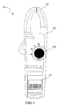
- FIG. 1 depicts an illustration of a clamp meter 100.
- the clamp meter has a primary body 110 that houses a control knob 112.
- the user-controlled control knob 112 can be set to an off position or other on states, such as measuring voltage, current, and resistance.
- the clamp meter also has a clamp 114 for attaching to electronic devices to be measured.
- the clamp meter can have a removable display 120.
- the removable display 120 does not have a separate user-controlled power setting.
- a clamp meter is used as an example for the primary unit and a detachable display is used as an example of the secondary unit throughout the discussion, the disclosure is not limited to this embodiment.
- the disclosure can be applied to any type of measurement tool that can be powered by batteries or any other portable power source.
- Non-limiting examples of measurement tools to which the disclosure is applicable include electrical measurement tools; environmental measurement tools that measure parameters such as air quality, temperature, humidity, carbon monoxide, carbon dioxide, and pressure; and chemical measurement tools that measure parameters such as pH, acidity, nitrogen content, oxygen content, phosphate content, and aluminum content for wastewater.
- FIGS. 2A and 2B depict block diagrams 200A and 200B illustrating a secondary unit attached to a primary unit and coupled via a magnetic actuator, when the primary unit has been placed in two different power states.
- FIG. 2A shows the primary unit 210 in an off state or standby mode
- FIG. 2B shows the primary unit 210 in an on state.
- the primary and secondary units do not have any conductive elements on the exterior.
- the primary unit was a clamp meter and a user used the clamp meter to measure a high voltage element, it would be very dangerous for the user if the clamp meter were to conduct the measured high-voltage to the interior of the clamp meter because the user could be shocked while using the device.
- the primary unit 210 has a user-controlled power controller 212.
- a user can set the power controller in either an off state or standby mode 212, as shown in FIG. 2A , or in an on state 213, as shown in FIG. 2B .
- the power controller can also be set for other power states that are not shown. Examples of a power controller include, but are not limited to, a switch, knob, toggle, and button.
- the power controller 212 is coupled to a magnet 214.
- the magnet 214 depicted in FIGS. 2A and 2B is a bar magnet, however the magnet can assume any shape or form.
- the magnet 214 is placed near the interior of the housing of the primary unit 210, such that the magnetic fields arising from the magnet 214 can be felt by a magnet 232 placed near the interior of the housing of the secondary unit 230 when the primary and secondary units are attached or in close proximity.
- the primary and secondary units can have additional parts that assist the units to attach more securely. For clarity, these additional parts are not shown. It will be recognized by a person of skill in the art that mechanisms for attaching the primary and secondary units can be used in conjunction with the magnetic actuator.
- the secondary unit's magnet When the primary and secondary units are attached and the primary unit is placed in the off or standby position by sliding the power controller 212 and correspondingly the primary unit's magnet 214 to the left, the secondary unit's magnet will also slide to the left as a result of the coupling magnetic fields between the magnets, as shown in FIG. 2A . Similarly, when the primary unit is placed in the on position by sliding the primary unit's power controller and magnet 214 to the right, the secondary unit's magnet will also slide to the right, as shown in FIG. 2B .
- the secondary unit's magnet 232 attached to the secondary unit's magnet 232 is a conductor 234.
- the secondary unit's magnet 232 can be electrically conductive and no additional conductor 234 would be needed.
- the primary magnet slides to the right, as shown in FIG. 2B , and the secondary magnet with its conductor 232 also slides to the right.
- the conductor makes contact with electrical contacts 238 that are part of the electrical circuit that couples the secondary unit's power supply 236 to the secondary unit's main electronics 240. Not shown in the figure are the electronics coupling the power supply source for the secondary unit that powers the unit's transceivers when the unit is in standby mode.
- Transceivers are devices that are used by the units to transmit and receive communications to and from each other.
- Non-limiting examples of transceivers include infrared transceivers, radio frequency transceivers, and two-way radios.
- the main electronics 240 for example a display, is shut off during standby mode, the transceiver electronics are still provided with sufficient power to operate.
- the power state of the secondary unit is coordinated with the user-controlled power state of the primary unit via the actuator mechanism.
- coordination of power states between the secondary unit and primary unit does not necessarily have to be one-to-one.
- the primary unit in addition to the off or standby state, can have more than one on state, for example, the primary unit can be set to measure different parameters in different on states.
- the secondary unit may only have one on state that corresponds to any of the on states of the primary unit, while the secondary unit's off or standby state corresponds directly to when the primary unit is placed in the off or standby state.
- the secondary unit can include an indicator that it has been placed in the standby or off state so that a user can immediately determine the status of the secondary unit.
- FIGS. 2C and 2D depict block diagrams 200C and 200D illustrating a secondary unit attached to a primary unit and coupled via a plastic actuator in two different power states.
- FIG. 2C shows the primary unit 260 in an off state or standby mode
- FIG. 2D shows the primary unit 270 in an on state.
- the primary unit 260 has a user-controlled power controller 262 that can be set in either an off state or standby mode 262, as shown in FIG. 2C , or in an on state 263, as shown in FIG. 2D .
- the power controller need not be a switch, but can take any form, for example, a knob or button.
- the power controller is coupled to a plunger 266 through an arm 264.
- the secondary unit 270 has a power supply 276 used to power the secondary unit's main electronics 280.
- the circuit between the power supply 276 and the main electronics 280 is a power supply switch.
- the switch includes two electrical contacts 278 that make contact with a conductor 272 that can take any suitable form, for example, a plate or bar.
- the conductor 272 is coupled via a spring 274 to a fixed location 275.
- the conductor 272 can be attached to fixed location 275 through any other structural mechanism, for example, the conductor 272 can be cantilevered in place. As shown in FIG.
- the spring 274 forces the conductor upwards to make contact with the electrical contacts 278, thus completing the circuit between the power supply 276 and the main electronics 280.
- the 'downward' direction is used in the description, the term 'downward' only refers to the relative direction between the primary and secondary units.
- the primary and secondary units can be enclosed with a seal along the surfaces of the units that come into close proximity when attached.
- the seal for one or both of the primary and secondary units can have the properties of a flexible membrane, bendable and non-conductive.
- the arm 264 pushes the plunger 266 downwards through the flexible membrane 265 of the primary unit 260 and the flexible membrane 271 of the secondary unit 270 to drive the conductor 272 downwards, away from the electrical contacts 278.
- the downward force of the plunger on the conductor 272 compresses the spring that pushes against the fixed location 275.
- the electrical path between the power supply 276 and the main electronics is interrupted, essentially placing the secondary unit in the off or standby mode.
- the power supply to the main electronics 280 is interrupted through the action of the actuator, the secondary circuit can still be in a low-power mode such that the transceivers (not shown) remain powered.
- FIG. 3 shows a block diagram 300 of a primary unit 310 and a secondary unit 350, according to an embodiment of the disclosure.
- the primary unit 310 can include one or more processors 320, RF transceivers 322, IR transceivers 324, power controllers 312, power supplies 314, and actuator mechanisms 316.
- the secondary unit 350 can include one or more processors 360, RF transceivers 362, IR transceivers 364, main electronics 356, power supplies 352, and power supply switches 354.
- the processors 320, 360 can be used to run applications for the primary and secondary units.
- the RF transceivers 322, 362 are used to transmit and receive radio frequency transmissions between the units, while the IR transceivers 324, 364 are used to transmit and receive infrared transmissions between the units.
- the power supplies 314, 352 can be batteries or any other portable direct current (DC) power source. Additionally or alternatively, the primary unit's power supply 314 can be an alternating current (AC) power source such as a wall outlet.
- the power controller 312 can be any user-controlled mechanism for placing the primary unit in different power states including, but not limited to, an on state and a standby state.
- the actuator mechanism 316 is used to couple the power state of the primary unit to the power supply switch 354 of the secondary unit when the units are attached to coordinate the power states of the two units. As described above, there may or may not be a one-to-one correspondence between the power states of the secondary unit and the power states of the primary unit.
- the power supply switch 354 can couple or interrupt the power supply 352 in the secondary unit to the main electronics 356.
- the main electronics 356 perform the main function of the secondary unit, for example, displaying data received from the primary unit.
- FIG. 4 is a flow chart 400 illustrating an example communication process 400 between a primary unit 310 and a secondary unit 350 when the units remain attached.
- the actions of the primary unit 310 on the left and the secondary unit 350 on the right are shown relative to each other as a function of time, with time increasing in the downwards direction in FIG. 4 . Transmissions from the primary unit to the secondary unit or vice versa are shown by the arrows crossing the center of FIG. 4 .
- the power controller on the primary unit 310 is turned on by a user in preparation to use the primary unit 310 in conjunction with the secondary unit 350.
- an actuator is triggered, and the circuit to the power supply in the secondary unit is completed so that the secondary unit is also turned on at block 430.
- the actuator mechanism can include, but is not limited to, a magnetic actuator and a non-conducting actuator.
- the infrared (IR) transceiver in the primary unit and the secondary unit are always on, irrespective of the power state of the units.
- the IR transceivers allow the primary and secondary units to communicate with each other in a low power mode while the units are attached.
- the transmission power of the transceivers can be adjusted such that when the primary and secondary units are detached, the units are no longer within IR range of each other.
- when the units remain within a short distance of each other they will still be within communication range. Beyond the IR range of the transceivers, the units will not be able to communicate via the IR transceivers.
- the units can use radio frequency (RF) transceivers to communicate with each other.
- RF transceivers require more power than the IR transceivers, the RF transceivers are more reliable over a longer distance and would be used when the units are detached.
- the primary unit uses its IR transceiver to ping the secondary unit using transmission 454. Because the units are attached, they are within IR range of the transceivers, and at block 432, the secondary unit receives the ping and transmits an acknowledgement to the primary unit using IR transmission 456. At block 413, the primary unit receives the acknowledgement. The primary unit periodically pings the secondary unit using its IR transceiver to ensure that the units are still attached. Thus, for each ping, blocks 412, 432, and 413 are repeated along with the appropriate transmissions 454, 456.
- the primary unit transmits data using an IR transceiver in transmission 450 to the secondary unit.
- the secondary unit receives the data and sends an acknowledgement 452 that the data has been received to the primary unit using its IR transceiver.
- the primary unit receives the acknowledgement.
- user controlled settings on the secondary unit are transmitted to the primary unit in acknowledgement 452. For example, if the secondary unit is a display and the primary unit is a clamp meter, a user may use buttons or other controls on the display to change the units or sensitivity of the display. These hardware setting changes are then sent back to the primary unit.
- the secondary unit After receiving the data, the secondary unit processes the data at block 436.
- the data from the primary unit is displayed by the secondary unit.
- the portion of the flow chart including blocks 414, 434, 416, and 436 along with appropriate transmissions 450, 452 can be repeated as many times as necessary for data to be transmitted from the primary to the secondary unit.
- the primary unit After the primary unit has transmitted the relevant data, the primary unit resumes pinging the secondary unit periodically to ensure that the units are still attached. Thus, again blocks 412, 432, and 413 are repeated, as necessary, along with the appropriate transmissions 454, 456.
- the power control on the primary unit is turned off by the user when the user is finished; this places the primary unit in a standby mode.
- the actuator in the primary unit is triggered, and the circuit to the power supply in the secondary unit is interrupted so that the main electronics, such as the display, in the secondary unit does not receive power from its power source and is effectively shut off at block 440.
- the secondary unit still operates in a standby mode where its IR transceiver is capable of transmitting and receiving IR communications.
- both the primary and secondary units are in standby mode, the units remain powered in a low-power mode so that the IR transceiver can still operate.
- the primary unit continues to periodically ping the secondary unit to ensure the units have not been detached.
- blocks 412, 432, and 413 are repeated, as necessary, along with the appropriate transmissions 454, 456.
- FIGS. 5A and 5B below will detail the case for when the units are detached and no longer within IR range.
- FIGS. 5A and 5B illustrate an example communication process 500A, 500B between a primary unit 310 and a secondary unit 350 when the units are initially attached but are subsequently detached and the primary unit is initially in standby mode.
- the actions of the primary unit 310 on the left and the secondary unit 350 on the right are shown relative to each other as a function of time, with time increasing in the downwards direction in FIGS. 5A and 5B . Transmissions from the primary unit to the secondary unit or vice versa are shown by the arrows crossing the center of FIGS. 5A and 5B .
- the primary unit is initially in standby mode, and the primary unit is attached to the secondary unit. Because the actuator mechanism in the primary unit coordinates the power states of the attached units, at block 550 the secondary unit is also placed in standby mode. At block 552, the secondary unit is detached from the primary unit by the user.
- the primary unit attempts to maintain contact with the secondary unit by periodically sending a brief IR transmission 580, such as a ping, block 516.
- a brief IR transmission 580 such as a ping
- the secondary unit awaits the periodic pings sent by the primary unit. If the secondary unit receives the ping, it transmits an acknowledgement at block 554 using transmission 582. Otherwise, if the secondary unit does not receive an IR ping after a predetermined time window has elapsed, the secondary unit turns on its RF transceiver at block 556.
- the predetermined time window is typically greater than the amount of time that elapses between periodic transmissions of the primary unit's pings.
- the primary unit receives any acknowledgement sent by the secondary unit.
- the primary unit If the primary unit does not receive an acknowledgement from the secondary unit at block 517, the primary unit turns on its RF transceiver. Although the RF transceivers in both of the units have been turned on, the IR transceivers in both units remain on, and the primary unit continues to periodically ping the secondary unit by repeating blocks 516, 554, and 517 with appropriate transmissions 580, 582. This process is used to determine whether the units are attached.
- the primary unit sends a ping in transmission 584 to the secondary unit using its RF transceiver.
- the secondary unit receives the ping and transmits an acknowledgement in transmission 586 back to the primary unit.
- the primary unit receives the acknowledgement at block 519.
- the primary unit continues to periodically ping the secondary unit using its IR transceiver but at a lower rate than it uses to ping the secondary unit using its RF transceiver. If the units are re-attached or come within IR range of each other again, the secondary unit will be able to pick up the IR pings from the primary unit and send an acknowledgement.
- the secondary unit When the secondary unit is able to receive the IR pings again, the secondary unit turns off its RF transceiver to save power. Similarly, when the primary unit receives an acknowledgement to its IR pings again, the primary unit also turns off its RF transceiver. The primary unit still continues to ping the secondary unit using its IR transceiver.
- the primary and secondary units are detached, as determined by whether the units are within IR range, and thus communicating using RF transceivers, when the primary unit is turned on by a user at block 520, at block 522 the primary unit transmits an RF command 588 to the secondary unit to turn on.
- the secondary unit receives the command at block 560 and sends an acknowledgement 590 back to the primary unit using its RF transceiver.
- the primary unit receives the acknowledgement, and at block 562, the secondary unit turns on.
- the secondary unit can be turned on by completing the circuit between the main electronics and the power supply as described above. Alternatively, a switch completing an alternative circuit to the power supply can be used to place the secondary unit in the on state.
- the primary unit transmits data to the secondary unit using its RF transceiver through transmission 591.
- the secondary unit receives the data at block 564 and transmits an acknowledgement 592.
- the primary unit receives the acknowledgement at block 528, and the secondary unit processes the data at block 566.
- the user places the primary unit in standby mode, while the secondary unit is detached.
- the IR transceivers remain powered to determine if the units are attached.
- the RF transceivers were on when the primary unit is placed in standby mode, the RF transceivers will also remain powered.
- the primary unit sends a command to the secondary unit to enter standby mode using RF transmission 593.
- the secondary unit receives the standby command and sends an acknowledgement 594 at block 568.
- the primary unit receives the acknowledgement at block 534.
- the secondary unit enters standby mode by interrupting power to all circuits except the IR and RF transceivers.
- the primary unit continues to send an IR ping to the secondary unit using transmission 595. Then at block 572, if the secondary unit receives the IR ping, the units are within IR range, and it sends an IR acknowledgement 596 back and turns off its RF transceiver to save power. If there is an acknowledgement sent, the primary unit receives the acknowledgement at block 538 and turns off its RF transceiver. Otherwise, the primary unit continues to periodically ping the secondary unit using its IR transceiver, repeating blocks 536, 572, and 538 and appropriate transmissions 595,596.
- the primary unit also sends an RF ping to the secondary unit periodically using transmission 597.
- the secondary unit receives the RF ping, it sends an RF acknowledgement 598 back. If the acknowledgement is sent, the primary unit receives it at block 542. Otherwise, the primary unit continues to periodically ping the secondary unit using its RF transceiver, repeating blocks 540, 574, and 542, with appropriate transmissions 597, 598. Note that the frequency of the IR pings is lower than the frequency of the RF pings.
- the units would be within IR range again, and both RF transceivers would turn off, as described above. Also, because the actuator in the primary unit coordinates the power states of the two units, no transmissions between the units are needed to coordinate the power states of the primary and secondary units when they are attached.
Landscapes
- Engineering & Computer Science (AREA)
- General Physics & Mathematics (AREA)
- Physics & Mathematics (AREA)
- Computer Networks & Wireless Communication (AREA)
- Power Engineering (AREA)
- Automation & Control Theory (AREA)
- Radar, Positioning & Navigation (AREA)
- Electromagnetism (AREA)
- General Engineering & Computer Science (AREA)
- Charge And Discharge Circuits For Batteries Or The Like (AREA)
- Selective Calling Equipment (AREA)
- Transceivers (AREA)
- Testing Electric Properties And Detecting Electric Faults (AREA)
Abstract
Description
- The present disclosure relates to coordinating power states of two or more detachable and re-attachable components of portable measurement tools.
- Measurement tools are often used in dangerous environments. In dangerous environments, a user of a measurement tool may be required to wear cumbersome personal protective gear for safety reasons, thus making it awkward, for example, to view the display of a measurement tool. Further, some measurement tools may need to be used in an awkward position that may not allow the instrument to be easily read. For example, a taut cable running vertically close to a wall into an electrical panel may need to be measured with a clamp meter. In order to attach the clamp meter to perform the measurement, the instrument might have to be held or positioned in such a manner that the display on the meter might not easily be visible to the user.
- In addition, the measurement may be difficult for a single person to perform given the particular measurement configuration. For example, a current measurement may need to be made with a clamp meter on a conductive cable in an electrical circuit for which the "on" switch is located in an electrical panel some distance away from the cable. In this scenario, two people may be necessary to safely facilitate the measurement. Alternatively, radio or other means of communication between the two people may also be required.
- A measurement tool may have a detachable portion for the convenience or safety of the user. In order to prevent user confusion as to the power state of each of the units, only the primary unit has a user-controllable power control. The power states of the two units are coordinated using an actuator mechanism when the units are attached. When the two units are detached, the state of the secondary unit is dependent upon the state of the primary unit and subsequent commands transmitted by the primary unit to the secondary unit.
- In accordance with an embodiment of the present invention, there is provided an apparatus that includes at least one detachable component, comprising:
- a primary unit configured to measure one or more parameters and further to receive power from a first power source, and wherein the primary unit is configured with a user-controlled power controller used for setting a primary power state of the primary unit, and further configured with an actuator, wherein the actuator is coupled to the user-controlled power controller; and
- a secondary unit configured to receive power from a second power source, and further configured to be detachable from the primary unit,
- wherein when the secondary unit is attached to the primary unit, the actuator coordinates the secondary power state of the secondary unit to the primary power state of the primary unit.
- Optional features of the embodiment may include:
- Wherein, when the secondary unit is detached from the primary unit, the secondary power state is determined at least by the primary power state and one or more commands from the primary unit.
- wherein the primary power state has at least an on state and a standby mode.
- wherein the primary unit has a non-conductive external surface.
- wherein the secondary unit has a non-conductive external surface.
- wherein the primary unit and the secondary unit are each configured to have an infrared transceiver for communicating with each other.
- wherein the primary unit and the secondary unit communicate using the infrared transceivers when attached to each other.
- wherein the primary unit and the secondary unit are each configured to have a radio frequency transceiver for communicating with each other.
- wherein the primary unit and the secondary unit communicate using the radio frequency transceivers when detached from each other.
- wherein the actuator is a magnetic actuator in the primary unit, and the magnetic actuator controls a magnetic switch in the secondary unit between a secondary power source and electronics in the secondary unit.
- wherein the actuator is a non-conductive actuator in the primary unit, and the non-conductive actuator controls a switch in the secondary unit between a secondary power source and electronics in the secondary unit.
- wherein coordinating the secondary power state of the secondary unit to the primary power state of the primary unit comprises:
- ■ placing the secondary unit in an on state if the primary unit is placed by the user in any on state; and
- ■ placing the secondary unit in a standby or off state if the primary unit placed by the user in a standby or off state.
- In accordance with another embodiment of the present invention, there is provided apparatus that coordinates power states between two attachable units, comprising:
- a primary unit, comprising:
- a first power supply configured to power at least a portion of the primary unit;
- a power controller coupled to the first power supply and configured to be controllable by a user, wherein the power controller can place the primary unit in one of at least two states:
- a primary on state, wherein all electronics in the primary unit are powered;
- and a primary standby state, wherein only communications electronics in the primary unit are powered; and
- an actuator coupled to the power controller and configured to respond to the power controller, wherein when the power controller places the primary unit in the primary on state, the actuator moves to a first actuator state that places a secondary unit in a secondary on state when attached to the main unit, and further wherein when the power controller places the primary unit in a primary standby state, the actuator moves to a second actuator state that places the secondary unit in a secondary standby state when attached to the main unit;
- the secondary unit, comprising:
- a secondary power supply configured to power at least a portion of the secondary unit and operate in one of at least two states:
- a secondary on state, wherein all electronics in the secondary unit are powered;
- a secondary standby state, wherein only communications electronics in the secondary unit are powered;
- a switch configured to interrupt the secondary power supply when the actuator moves to the first actuator state and the secondary unit is attached to the primary unit, and to couple the secondary power supply when the actuator moves to the second actuator state and the secondary unit is attached to the primary unit; and
- at least one processor coupled among the secondary power supply, the secondary infrared transceiver, the secondary radio frequency transceiver, and the switch, wherein the processor is configured to:
- process communications from the primary unit;
- based upon the communications, place the secondary power supply in an appropriate state.
- a secondary power supply configured to power at least a portion of the secondary unit and operate in one of at least two states:
- Optional features of the embodiment may include:
- wherein the primary unit has a non-conductive external surface.
- wherein the secondary unit has a non-conductive external surface.
- wherein the communications electronics in the primary unit and the secondary unit each include an infrared transceiver.
- wherein when the primary unit and the secondary unit are attached, they communicate using the infrared transceivers.
- wherein the communications electronics in the primary unit and the secondary unit each include a radio frequency transceiver.
- wherein when the primary unit and the secondary unit are detached, they communicate using the radio frequency transceivers.
- wherein the actuator is a magnetic actuator.
- wherein the actuator is a non-conducting actuator.
- In accordance with an aspect of the present invention, there is provided a method of coordinating power states between two detachable units of an apparatus, comprising:
- when the two units are detached, upon detecting a first change in power status of a primary unit from standby mode to on, transmitting a first command from the primary unit to a secondary unit to turn on; and
- when the two units are detached, upon detecting a second change in power status of the primary unit from on to standby mode, transmitting a second command from the primary unit to the secondary unit to go to standby mode.
- In accordance with another aspect of the present invention, there is provided a method of coordinating power states between two detachable units of an apparatus, comprising:
- when the two units are attached, upon a first change in power status of a primary unit from on to standby mode, triggering an actuator to interrupt a secondary power supply in a secondary unit; and
- when the two units are attached, upon a second change in power status of the primary unit from standby mode to on, triggering an actuator to connect a secondary power supply in a secondary unit.
- In accordance with another aspect of the present invention, there is provided a method of coordinating power states between two detachable units of an apparatus, comprising:
- if the two units are attached, permitting a secondary power state of a secondary unit to be controlled by a primary power state of the primary unit via an actuator, wherein when the primary power state is on or in standby mode, the secondary power state is correspondingly placed in on or standby mode, respectively; and
- if the two units are not attached,
turning on a radio frequency transceiver in the primary and secondary units;
if the primary power sate changes, transmitting a first command from the primary unit to the secondary unit using the radio frequency transceiver to change the secondary power state. - Examples of power state coordination between two detachable units are illustrated in the figures. The examples and figures are illustrative rather than limiting.
-
FIG. 1 shows a picture of a clamp meter. -
FIGS. 2A and 2B show block diagrams illustrating a secondary unit attached to a primary unit and coupled via a magnetic actuator, when the primary unit has been placed in two different power states, according to an embodiment of the disclosure. -
FIGS. 2C and 2D show block diagrams illustrating a secondary unit attached to a primary unit and coupled via a non-conducting actuator, when the primary unit has been placed in two different power states, according to an embodiment of the disclosure. -
FIG. 3 shows a block diagram of a primary unit and a secondary unit, according to an embodiment of the disclosure. -
FIG. 4 depicts a flow diagram illustrating an example communication process between a primary unit and a secondary unit when the units are attached. -
FIGS. 5A and5B depict a flow diagram illustrating an example communication process between a primary unit and a secondary unit when the units are initially attached but are subsequently detached. - The following description and drawings are illustrative and are not to be construed as limiting. Numerous specific details are described to provide a thorough understanding of the disclosure. However, in certain instances, well-known or conventional details are not described in order to avoid obscuring the description.
- Without intent to further limit the scope of the disclosure, examples of instruments, apparatus, methods and their related results according to the embodiments of the present disclosure are given below. Reference in this specification to "one embodiment" or "an embodiment" means that a particular feature, structure, or characteristic described in connection with the embodiment is included in at least one embodiment of the disclosure. The appearances of the phrase "in one embodiment" in various places in the specification are not necessarily all referring to the same embodiment, nor are separate or alternative embodiments mutually exclusive of other embodiments. Moreover, various features are described which may be exhibited by some embodiments and not by others. Similarly, various requirements are described which may be requirements for some embodiments but not other embodiments.
- The terms used in this specification generally have their ordinary meanings in the art, within the context of the disclosure, and in the specific context where each term is used. Certain terms that are used to describe the disclosure are discussed below, or elsewhere in the specification, to provide additional guidance to the practitioner regarding the description of the disclosure. The use of examples anywhere in this specification including examples of any terms discussed herein is illustrative only, and is not intended to further limit the scope and meaning of the disclosure or of any exemplified term. Likewise, the disclosure is not limited to various embodiments given in this specification.
- The terminology used in the description presented below is intended to be interpreted in its broadest reasonable manner, even though it is being used in conjunction with a detailed description of certain specific examples of the invention. Certain terms may even be emphasized below; however, any terminology intended to be interpreted in any restricted manner will be overtly and specifically defined as such in this Detailed Description section.
- In accordance with an exemplary embodiment to be described below, a measurement tool includes one or more components that are detachable. One application where a detachable tool component would be useful is a clamp multimeter (clamp meter) that has a detachable display. For example, the clamp meter may need to be used on cables situated in a location that is hard to access. Thus, if the display were fixed to the clamp meter, it would be inconvenient for a user to view and read the display. In some situations, the environment in which the clamp meter needs to be used requires the user to wear cumbersome personal protective equipment. A removable remote display would allow a second user to view the display while the first user attached the meter to the desired location. In addition, the removable display eliminates the need for communication equipment between two users, and/or unnecessary walking around near, for example, a dangerous access panel.
- When one component of an instrument, referred to herein as a secondary unit, is detached from the main instrument or primary unit, the two units need to be able to communicate wirelessly with each other. This problem does not arise when the two components are not detachable because there are wires internal to the instrument over which signals can be transmitted between the components.
- Moreover, when the primary and secondary units of an instrument are not detachable, a single power controller on the instrument can be used by a user to turn on the components of the instrument or to place the instrument in any desired power state, including a power-saving mode. However, when the units are detachable, in order to prevent user confusion as to the power state of each of the units, it is desirable to not have separate power controllers on each unit. For example, measuring a high voltage with a clamp meter can be risky because if the user forgets to turn on the display, the user may think that there is no voltage although there is high voltage present. Thus, only the primary unit should have a user-controllable power control.
- Additionally, when there are two or more detachable units that are powered by portable power sources, it is advantageous for the units to know when they are mated, in order to establish a power source management solution to save power. When the units are mated, the power states of the two units are coordinated through the used of an actuator mechanism, and an infrared (IR) transceiver, which has a low power draw, can be used to communicate between the units. When the units are not mated, a different communication method would be used, such as a radio frequency (RF) transceiver radio. While the power draw of the RF transceiver is higher, the distance over which the units can communicate is much greater that that of IR transceivers. Further, when the user turns off or puts the primary unit in standby mode to save power, the secondary unit should also be placed in standby mode to save power because if the power source of the secondary unit has been depleted, the primary unit will not be able to effectively function.
-
FIG. 1 depicts an illustration of aclamp meter 100. The clamp meter has aprimary body 110 that houses acontrol knob 112. As depicted inFIG. 1 , the user-controlledcontrol knob 112 can be set to an off position or other on states, such as measuring voltage, current, and resistance. In one embodiment, when the display is detachable, there can be a standby mode in addition to or instead of the off position. The clamp meter also has aclamp 114 for attaching to electronic devices to be measured. The clamp meter can have aremovable display 120. Theremovable display 120 does not have a separate user-controlled power setting. - Although a clamp meter is used as an example for the primary unit and a detachable display is used as an example of the secondary unit throughout the discussion, the disclosure is not limited to this embodiment. The disclosure can be applied to any type of measurement tool that can be powered by batteries or any other portable power source. Non-limiting examples of measurement tools to which the disclosure is applicable include electrical measurement tools; environmental measurement tools that measure parameters such as air quality, temperature, humidity, carbon monoxide, carbon dioxide, and pressure; and chemical measurement tools that measure parameters such as pH, acidity, nitrogen content, oxygen content, phosphate content, and aluminum content for wastewater.
-
FIGS. 2A and 2B depict block diagrams 200A and 200B illustrating a secondary unit attached to a primary unit and coupled via a magnetic actuator, when the primary unit has been placed in two different power states.FIG. 2A shows theprimary unit 210 in an off state or standby mode, whileFIG. 2B shows theprimary unit 210 in an on state. - Note that for safety considerations, in one embodiment the primary and secondary units do not have any conductive elements on the exterior. For example, if the primary unit was a clamp meter and a user used the clamp meter to measure a high voltage element, it would be very dangerous for the user if the clamp meter were to conduct the measured high-voltage to the interior of the clamp meter because the user could be shocked while using the device.
- The
primary unit 210 has a user-controlledpower controller 212. A user can set the power controller in either an off state orstandby mode 212, as shown inFIG. 2A , or in an onstate 213, as shown inFIG. 2B . The power controller can also be set for other power states that are not shown. Examples of a power controller include, but are not limited to, a switch, knob, toggle, and button. Thepower controller 212 is coupled to amagnet 214. Themagnet 214 depicted inFIGS. 2A and 2B is a bar magnet, however the magnet can assume any shape or form. In one embodiment, themagnet 214 is placed near the interior of the housing of theprimary unit 210, such that the magnetic fields arising from themagnet 214 can be felt by amagnet 232 placed near the interior of the housing of thesecondary unit 230 when the primary and secondary units are attached or in close proximity. The primary and secondary units can have additional parts that assist the units to attach more securely. For clarity, these additional parts are not shown. It will be recognized by a person of skill in the art that mechanisms for attaching the primary and secondary units can be used in conjunction with the magnetic actuator. - When the primary and secondary units are attached and the primary unit is placed in the off or standby position by sliding the
power controller 212 and correspondingly the primary unit'smagnet 214 to the left, the secondary unit's magnet will also slide to the left as a result of the coupling magnetic fields between the magnets, as shown inFIG. 2A . Similarly, when the primary unit is placed in the on position by sliding the primary unit's power controller andmagnet 214 to the right, the secondary unit's magnet will also slide to the right, as shown inFIG. 2B . - In one embodiment, attached to the secondary unit's
magnet 232 is aconductor 234. In an alternative embodiment, the secondary unit'smagnet 232 can be electrically conductive and noadditional conductor 234 would be needed. When the primary unit is placed in the on state, the primary magnet slides to the right, as shown inFIG. 2B , and the secondary magnet with itsconductor 232 also slides to the right. The conductor makes contact withelectrical contacts 238 that are part of the electrical circuit that couples the secondary unit'spower supply 236 to the secondary unit'smain electronics 240. Not shown in the figure are the electronics coupling the power supply source for the secondary unit that powers the unit's transceivers when the unit is in standby mode. Transceivers are devices that are used by the units to transmit and receive communications to and from each other. Non-limiting examples of transceivers include infrared transceivers, radio frequency transceivers, and two-way radios. Although themain electronics 240, for example a display, is shut off during standby mode, the transceiver electronics are still provided with sufficient power to operate. Thus, when the primary and secondary units are attached, the power state of the secondary unit is coordinated with the user-controlled power state of the primary unit via the actuator mechanism. In one embodiment, coordination of power states between the secondary unit and primary unit does not necessarily have to be one-to-one. For example, in addition to the off or standby state, the primary unit can have more than one on state, for example, the primary unit can be set to measure different parameters in different on states. However, the secondary unit may only have one on state that corresponds to any of the on states of the primary unit, while the secondary unit's off or standby state corresponds directly to when the primary unit is placed in the off or standby state. In one embodiment, the secondary unit can include an indicator that it has been placed in the standby or off state so that a user can immediately determine the status of the secondary unit. -
FIGS. 2C and 2D depict block diagrams 200C and 200D illustrating a secondary unit attached to a primary unit and coupled via a plastic actuator in two different power states.FIG. 2C shows theprimary unit 260 in an off state or standby mode, whileFIG. 2D shows theprimary unit 270 in an on state. - Similar to the above description, the
primary unit 260 has a user-controlledpower controller 262 that can be set in either an off state orstandby mode 262, as shown inFIG. 2C , or in an onstate 263, as shown inFIG. 2D . For clarity, other states that the primary unit can be set to are not shown. The power controller need not be a switch, but can take any form, for example, a knob or button. The power controller is coupled to aplunger 266 through anarm 264. - The
secondary unit 270 has apower supply 276 used to power the secondary unit'smain electronics 280. The circuit between thepower supply 276 and themain electronics 280 is a power supply switch. The switch includes twoelectrical contacts 278 that make contact with aconductor 272 that can take any suitable form, for example, a plate or bar. In one embodiment, theconductor 272 is coupled via aspring 274 to a fixedlocation 275. Theconductor 272 can be attached to fixedlocation 275 through any other structural mechanism, for example, theconductor 272 can be cantilevered in place. As shown inFIG. 2C , when there is no downward force on theconductor 272, thespring 274 forces the conductor upwards to make contact with theelectrical contacts 278, thus completing the circuit between thepower supply 276 and themain electronics 280. Although the 'downward' direction is used in the description, the term 'downward' only refers to the relative direction between the primary and secondary units. - In one embodiment, to prevent violation of creepage and clearance requirements, the primary and secondary units can be enclosed with a seal along the surfaces of the units that come into close proximity when attached. The seal for one or both of the primary and secondary units can have the properties of a flexible membrane, bendable and non-conductive. As shown in
FIG. 2D , when thepower controller 262 is moved to the off state orstandby mode 263, thearm 264 pushes theplunger 266 downwards through theflexible membrane 265 of theprimary unit 260 and theflexible membrane 271 of thesecondary unit 270 to drive theconductor 272 downwards, away from theelectrical contacts 278. The downward force of the plunger on theconductor 272 compresses the spring that pushes against the fixedlocation 275. Thus, the electrical path between thepower supply 276 and the main electronics is interrupted, essentially placing the secondary unit in the off or standby mode. Although the power supply to themain electronics 280 is interrupted through the action of the actuator, the secondary circuit can still be in a low-power mode such that the transceivers (not shown) remain powered. -
FIG. 3 shows a block diagram 300 of aprimary unit 310 and asecondary unit 350, according to an embodiment of the disclosure. Theprimary unit 310 can include one ormore processors 320,RF transceivers 322,IR transceivers 324,power controllers 312,power supplies 314, andactuator mechanisms 316. Thesecondary unit 350 can include one ormore processors 360,RF transceivers 362,IR transceivers 364,main electronics 356,power supplies 352, and power supply switches 354. - The
processors RF transceivers IR transceivers power supply 314 can be an alternating current (AC) power source such as a wall outlet. Thepower controller 312 can be any user-controlled mechanism for placing the primary unit in different power states including, but not limited to, an on state and a standby state. Theactuator mechanism 316 is used to couple the power state of the primary unit to thepower supply switch 354 of the secondary unit when the units are attached to coordinate the power states of the two units. As described above, there may or may not be a one-to-one correspondence between the power states of the secondary unit and the power states of the primary unit. Thepower supply switch 354 can couple or interrupt thepower supply 352 in the secondary unit to themain electronics 356. Themain electronics 356 perform the main function of the secondary unit, for example, displaying data received from the primary unit. -
FIG. 4 is aflow chart 400 illustrating anexample communication process 400 between aprimary unit 310 and asecondary unit 350 when the units remain attached. The actions of theprimary unit 310 on the left and thesecondary unit 350 on the right are shown relative to each other as a function of time, with time increasing in the downwards direction inFIG. 4 . Transmissions from the primary unit to the secondary unit or vice versa are shown by the arrows crossing the center ofFIG. 4 . - At
block 410, the power controller on theprimary unit 310 is turned on by a user in preparation to use theprimary unit 310 in conjunction with thesecondary unit 350. When the primary unit is turned on, an actuator is triggered, and the circuit to the power supply in the secondary unit is completed so that the secondary unit is also turned on atblock 430. As described above, the actuator mechanism can include, but is not limited to, a magnetic actuator and a non-conducting actuator. - In one embodiment, the infrared (IR) transceiver in the primary unit and the secondary unit are always on, irrespective of the power state of the units. The IR transceivers allow the primary and secondary units to communicate with each other in a low power mode while the units are attached. In one embodiment, the transmission power of the transceivers can be adjusted such that when the primary and secondary units are detached, the units are no longer within IR range of each other. In another embodiment, when the units remain within a short distance of each other, they will still be within communication range. Beyond the IR range of the transceivers, the units will not be able to communicate via the IR transceivers. As described below, when the units are detached, the units can use radio frequency (RF) transceivers to communicate with each other. Although the RF transceivers require more power than the IR transceivers, the RF transceivers are more reliable over a longer distance and would be used when the units are detached.
- At
block 412, the primary unit uses its IR transceiver to ping the secondaryunit using transmission 454. Because the units are attached, they are within IR range of the transceivers, and atblock 432, the secondary unit receives the ping and transmits an acknowledgement to the primary unit usingIR transmission 456. Atblock 413, the primary unit receives the acknowledgement. The primary unit periodically pings the secondary unit using its IR transceiver to ensure that the units are still attached. Thus, for each ping, blocks 412, 432, and 413 are repeated along with theappropriate transmissions - At
block 414 the primary unit transmits data using an IR transceiver intransmission 450 to the secondary unit. For example, if the secondary unit were a display unit, the primary unit would transmit data to be shown on the display. Atblock 434, the secondary unit receives the data and sends anacknowledgement 452 that the data has been received to the primary unit using its IR transceiver. Atblock 416, the primary unit receives the acknowledgement. In one embodiment, user controlled settings on the secondary unit are transmitted to the primary unit inacknowledgement 452. For example, if the secondary unit is a display and the primary unit is a clamp meter, a user may use buttons or other controls on the display to change the units or sensitivity of the display. These hardware setting changes are then sent back to the primary unit. After receiving the data, the secondary unit processes the data atblock 436. For the example where the secondary unit is a display, atblock 436, the data from the primary unit is displayed by the secondary unit. The portion of the flowchart including blocks appropriate transmissions - After the primary unit has transmitted the relevant data, the primary unit resumes pinging the secondary unit periodically to ensure that the units are still attached. Thus, again blocks 412, 432, and 413 are repeated, as necessary, along with the
appropriate transmissions - At
block 418, the power control on the primary unit is turned off by the user when the user is finished; this places the primary unit in a standby mode. In response, the actuator in the primary unit is triggered, and the circuit to the power supply in the secondary unit is interrupted so that the main electronics, such as the display, in the secondary unit does not receive power from its power source and is effectively shut off atblock 440. Although the display may be off, the secondary unit still operates in a standby mode where its IR transceiver is capable of transmitting and receiving IR communications. When both the primary and secondary units are in standby mode, the units remain powered in a low-power mode so that the IR transceiver can still operate. The primary unit continues to periodically ping the secondary unit to ensure the units have not been detached. Thus, again blocks 412, 432, and 413 are repeated, as necessary, along with theappropriate transmissions FIGS. 5A and5B below will detail the case for when the units are detached and no longer within IR range. -
FIGS. 5A and5B illustrate anexample communication process primary unit 310 and asecondary unit 350 when the units are initially attached but are subsequently detached and the primary unit is initially in standby mode. The actions of theprimary unit 310 on the left and thesecondary unit 350 on the right are shown relative to each other as a function of time, with time increasing in the downwards direction inFIGS. 5A and5B . Transmissions from the primary unit to the secondary unit or vice versa are shown by the arrows crossing the center ofFIGS. 5A and5B . - At
block 510, the primary unit is initially in standby mode, and the primary unit is attached to the secondary unit. Because the actuator mechanism in the primary unit coordinates the power states of the attached units, atblock 550 the secondary unit is also placed in standby mode. Atblock 552, the secondary unit is detached from the primary unit by the user. - Whether or not the units are attached, the primary unit attempts to maintain contact with the secondary unit by periodically sending a
brief IR transmission 580, such as a ping, block 516. Atblock 554, the secondary unit awaits the periodic pings sent by the primary unit. If the secondary unit receives the ping, it transmits an acknowledgement atblock 554 usingtransmission 582. Otherwise, if the secondary unit does not receive an IR ping after a predetermined time window has elapsed, the secondary unit turns on its RF transceiver atblock 556. The predetermined time window is typically greater than the amount of time that elapses between periodic transmissions of the primary unit's pings. Atblock 517, the primary unit receives any acknowledgement sent by the secondary unit. If the primary unit does not receive an acknowledgement from the secondary unit atblock 517, the primary unit turns on its RF transceiver. Although the RF transceivers in both of the units have been turned on, the IR transceivers in both units remain on, and the primary unit continues to periodically ping the secondary unit by repeatingblocks appropriate transmissions - At
block 518, the primary unit sends a ping intransmission 584 to the secondary unit using its RF transceiver. Atblock 558, the secondary unit receives the ping and transmits an acknowledgement intransmission 586 back to the primary unit. The primary unit receives the acknowledgement atblock 519. The primary unit continues to periodically ping the secondary unit using its IR transceiver but at a lower rate than it uses to ping the secondary unit using its RF transceiver. If the units are re-attached or come within IR range of each other again, the secondary unit will be able to pick up the IR pings from the primary unit and send an acknowledgement. When the secondary unit is able to receive the IR pings again, the secondary unit turns off its RF transceiver to save power. Similarly, when the primary unit receives an acknowledgement to its IR pings again, the primary unit also turns off its RF transceiver. The primary unit still continues to ping the secondary unit using its IR transceiver. - If the primary and secondary units are detached, as determined by whether the units are within IR range, and thus communicating using RF transceivers, when the primary unit is turned on by a user at
block 520, atblock 522 the primary unit transmits anRF command 588 to the secondary unit to turn on. The secondary unit receives the command atblock 560 and sends anacknowledgement 590 back to the primary unit using its RF transceiver. Atblock 524, the primary unit receives the acknowledgement, and atblock 562, the secondary unit turns on. The secondary unit can be turned on by completing the circuit between the main electronics and the power supply as described above. Alternatively, a switch completing an alternative circuit to the power supply can be used to place the secondary unit in the on state. - At
block 526, the primary unit transmits data to the secondary unit using its RF transceiver throughtransmission 591. The secondary unit receives the data atblock 564 and transmits anacknowledgement 592. The primary unit receives the acknowledgement atblock 528, and the secondary unit processes the data atblock 566. - At
block 530, the user places the primary unit in standby mode, while the secondary unit is detached. In standby mode, the IR transceivers remain powered to determine if the units are attached. In addition, if the RF transceivers were on when the primary unit is placed in standby mode, the RF transceivers will also remain powered. - At
block 532, the primary unit sends a command to the secondary unit to enter standby mode usingRF transmission 593. The secondary unit receives the standby command and sends anacknowledgement 594 atblock 568. The primary unit receives the acknowledgement atblock 534. As a result of the command, the secondary unit enters standby mode by interrupting power to all circuits except the IR and RF transceivers. - At
block 536, the primary unit continues to send an IR ping to the secondaryunit using transmission 595. Then atblock 572, if the secondary unit receives the IR ping, the units are within IR range, and it sends anIR acknowledgement 596 back and turns off its RF transceiver to save power. If there is an acknowledgement sent, the primary unit receives the acknowledgement atblock 538 and turns off its RF transceiver. Otherwise, the primary unit continues to periodically ping the secondary unit using its IR transceiver, repeatingblocks - Meanwhile, the primary unit also sends an RF ping to the secondary unit periodically using
transmission 597. Atblock 574, if the secondary unit receives the RF ping, it sends anRF acknowledgement 598 back. If the acknowledgement is sent, the primary unit receives it atblock 542. Otherwise, the primary unit continues to periodically ping the secondary unit using its RF transceiver, repeatingblocks appropriate transmissions - If the secondary unit were re-attached to the primary unit, the units would be within IR range again, and both RF transceivers would turn off, as described above. Also, because the actuator in the primary unit coordinates the power states of the two units, no transmissions between the units are needed to coordinate the power states of the primary and secondary units when they are attached.
- Unless the context clearly requires otherwise, throughout the description and the claims, the words "comprise," "comprising," and the like are to be construed in an inclusive sense, as opposed to an exclusive or exhaustive sense; that is to say, in the sense of "including, but not limited to." As used herein, the terms "connected," "coupled," or any variant thereof, means any connection or coupling, either direct or indirect, between two or more elements; the coupling of connection between the elements can be physical, logical, or a combination thereof. Additionally, the words "herein," "above," "below," and words of similar import, when used in this patent application, shall refer to this application as a whole and not to any particular portions of this application. Where the context permits, words in the above Detailed Description using the singular or plural number may also include the plural or singular number respectively. The word "or," in reference to a list of two or more items, covers all of the following interpretations of the word: any of the items in the list, all of the items in the list, and any combination of the items in the list.
- The above detailed description of embodiments of the disclosure is not intended to be exhaustive or to limit the teachings to the precise form disclosed above. While specific embodiments of, and examples for, the disclosure are described above for illustrative purposes, various equivalent modifications are possible within the scope of the disclosure, as those skilled in the relevant art will recognize. For example, while processes or blocks are presented in a given order, alternative embodiments may perform routines having steps, or employ systems having blocks, in a different order, and some processes or blocks may be deleted, moved, added, subdivided, combined, and/or modified to provide alternative or sub-combinations. Each of these processes or blocks may be implemented in a variety of different ways. Also, while processes or blocks are at times shown as being performed in series, these processes or blocks may instead be performed in parallel, or may be performed at different times. Further any specific numbers noted herein are only examples: alternative implementations may employ differing values or ranges.
- The teachings of the disclosure provided herein can be applied to other systems, not necessarily the system described above. The elements and acts of the various embodiments described above can be combined to provide further embodiments.
- While the above description describes certain embodiments of the disclosure, and describes the best mode contemplated, no matter how detailed the above appears in text, the teachings can be practiced in many ways. Details of the system may vary considerably in its implementation details, while still being encompassed by the subject matter disclosed herein. As noted above, particular terminology used when describing certain features or aspects of the disclosure should not be taken to imply that the terminology is being redefined herein to be restricted to any specific characteristics, features, or aspects of the disclosure with which that terminology is associated. In general, the terms used in the following claims should not be construed to limit the disclosure to the specific embodiments disclosed in the specification, unless the above Detailed Description section explicitly defines such terms. Accordingly, the actual scope of the disclosure encompasses not only the disclosed embodiments, but also all equivalent ways of practicing or implementing the disclosure under the claims.
Claims (15)
- An apparatus that includes at least one detachable component, comprising:a primary unit configured to receive power from a first power source, and wherein the primary unit is configured with a user-controlled power controller used for setting a primary power state of the primary unit, and further configured with an actuator, wherein the actuator is coupled to the user-controlled power controller; anda secondary unit configured to receive power from a second power source, and further configured to be detachable from the primary unit,wherein, when the secondary unit is attached to the primary unit, the actuator coordinates the secondary power state of the secondary unit to the primary power state of the primary unit.
- Apparatus as claimed in claim 1, wherein, when the secondary unit is detached from the primary unit, the secondary power state is determined at least by the primary power state and one or more commands from the primary unit.
- Apparatus as claimed in claim 1 or 2, wherein the primary power state has at least an on state and a standby mode.
- Apparatus as claimed in claim 1, 2 or 3,
wherein the primary unit has a non-conductive external surface; and/or
wherein the secondary unit has a non-conductive external surface. - Apparatus as claimed in any preceding claim, wherein the primary unit and the secondary unit are each configured to have an infrared transceiver for communicating with each other.
- Apparatus as claimed in claim 5, wherein the primary unit and the secondary unit communicate using the infrared transceivers when attached to each other.
- Apparatus as claimed in any preceding claim, wherein the primary unit and the secondary unit are each configured to have a radio frequency transceiver for communicating with each other.
- Apparatus as claimed in claim 7, wherein the primary unit and the secondary unit communicate using the radio frequency transceivers when detached from each other.
- Apparatus as claimed in any preceding claim, wherein
the actuator is a magnetic actuator in the primary unit, and the magnetic actuator controls a magnetic switch in the secondary unit between a secondary power source and electronics in the secondary unit; or
the actuator is a non-conductive actuator in the primary unit, and the non-conductive actuator controls a switch in the secondary unit between a secondary power source and electronics in the secondary unit. - Apparatus as claimed in any preceding claim, wherein coordinating the secondary power state of the secondary unit to the primary power state of the primary unit comprises:placing the secondary unit in an on state if the primary unit is placed by the user in any on state; andplacing the secondary unit in a standby or off state if the primary unit is placed by the user in a standby or off state.
- Apparatus as claimed in any preceding claim, wherein the primary unit is configured to measure one or more parameters.
- Apparatus as claimed in claim 3, or any of claims 4 to 11 when dependent on claim 3, wherein the actuator coupled to the power controller is configured to respond to the power controller, wherein, when the power controller places the primary unit in the primary on state, the actuator moves to a first actuator state that places the secondary unit in a secondary on state when attached to the main unit.
- Apparatus as claimed in claim 12, wherein, when the power controller places the primary unit in a primary standby state, the actuator moves to a second actuator state that places the secondary unit in a secondary standby state when attached to the primary unit.
- A method of coordinating power states between two detachable units of an apparatus, comprising:when the two units are detached, upon detecting a first change in power status of a primary unit from standby mode to on, transmitting a first command from the primary unit to a secondary unit to turn on; andwhen the two units are detached, upon detecting a second change in power status of the primary unit from on to standby mode, transmitting a second command from the primary unit to the secondary unit to go to standby mode;and/orwhen the two units are attached, upon a first change in power status of a primary unit from on to standby mode, triggering an actuator to interrupt a secondary power supply in a secondary unit; andwhen the two units are attached, upon a second change in power status of the primary unit from standby mode to on, triggering an actuator to connect a secondary power supply in a secondary unit.
- A method as claimed in claim 14, in which,
when the two units are attached,
permitting a secondary power state of a secondary unit to be controlled by a primary power state of the primary unit via an actuator, wherein when the primary power state is on or in standby mode, the secondary power state is correspondingly placed in on or standby mode, respectively; and
when the two units are not attached,
turning on a radio frequency transceiver in the primary and secondary units;
if the primary power sate changes, transmitting a first command from the primary unit to the secondary unit using the radio frequency transceiver to change the secondary power state.
Applications Claiming Priority (1)
| Application Number | Priority Date | Filing Date | Title |
|---|---|---|---|
| US12/505,417 US8856555B2 (en) | 2009-07-17 | 2009-07-17 | Power state coordination for portable test tools |
Publications (3)
| Publication Number | Publication Date |
|---|---|
| EP2276008A2 true EP2276008A2 (en) | 2011-01-19 |
| EP2276008A3 EP2276008A3 (en) | 2017-11-22 |
| EP2276008B1 EP2276008B1 (en) | 2019-09-04 |
Family
ID=43242214
Family Applications (1)
| Application Number | Title | Priority Date | Filing Date |
|---|---|---|---|
| EP10169934.6A Active EP2276008B1 (en) | 2009-07-17 | 2010-07-16 | Power state coordination for portable test tools |
Country Status (4)
| Country | Link |
|---|---|
| US (2) | US8856555B2 (en) |
| EP (1) | EP2276008B1 (en) |
| CN (1) | CN101958571B (en) |
| TW (2) | TWI569232B (en) |
Families Citing this family (23)
| Publication number | Priority date | Publication date | Assignee | Title |
|---|---|---|---|---|
| US8856555B2 (en) * | 2009-07-17 | 2014-10-07 | Fluke Corporation | Power state coordination for portable test tools |
| US9615147B2 (en) * | 2010-05-17 | 2017-04-04 | Flir Systems, Inc. | Multisensory meter system |
| US9121870B2 (en) * | 2010-10-18 | 2015-09-01 | Milwaukee Electric Tool Corporation | Clamp meter with detachable clamp and clamp storage area |
| US20130051572A1 (en) * | 2010-12-08 | 2013-02-28 | Creative Technology Ltd | Method for optimizing reproduction of audio signals from an apparatus for audio reproduction |
| EP2663020B1 (en) * | 2011-01-06 | 2019-07-24 | LG Electronics Inc. | Network system |
| JP2013113822A (en) * | 2011-11-30 | 2013-06-10 | Hioki Ee Corp | Measurement device |
| JP2013120077A (en) * | 2011-12-06 | 2013-06-17 | Hioki Ee Corp | Measuring device |
| CN102944781A (en) * | 2012-11-06 | 2013-02-27 | 西安开容电子技术有限责任公司 | Miniaturized current test caliper |
| CN102944701A (en) * | 2012-11-06 | 2013-02-27 | 西安开容电子技术有限责任公司 | Wide-frequency-band current testing calipers |
| CN104932662B (en) * | 2014-03-17 | 2018-08-10 | 联想(北京)有限公司 | A kind of control method and electronic equipment |
| US20160305986A1 (en) * | 2014-04-21 | 2016-10-20 | Timothy Shane McClure | Device for Detecting and Measuring the Current and Voltage of Electric Circuits in a Building |
| US10546112B2 (en) * | 2015-08-17 | 2020-01-28 | Ricoh Company, Ltd. | Apparatus, authentication process method, and computer program product |
| TWI650633B (en) * | 2017-10-06 | 2019-02-11 | 財團法人國家實驗研究院 | Modular electronic combination device |
| USD848879S1 (en) * | 2017-11-15 | 2019-05-21 | Chauvin Arnoux | Apparatus for measuring electrical parameters |
| EP3550291A1 (en) * | 2018-04-05 | 2019-10-09 | Georg Fischer Rohrleitungssysteme AG | Fastening device for measuring devices on pipes |
| US10908188B2 (en) * | 2018-05-11 | 2021-02-02 | Fluke Corporation | Flexible jaw probe for non-contact electrical parameter measurement |
| WO2020231974A1 (en) | 2019-05-13 | 2020-11-19 | Milwaukee Electric Tool Corporation | Contactless trigger with rotational magnetic sensor for a power tool |
| USD938843S1 (en) * | 2019-08-28 | 2021-12-21 | Fluke Corporation | Clamp meter |
| CN114868513A (en) | 2021-02-05 | 2022-08-09 | 米沃奇电动工具公司 | Contactless switch for lawn mowers |
| USD973522S1 (en) * | 2021-02-23 | 2022-12-27 | Fluke Corporation | Clamp meter |
| USD1049890S1 (en) * | 2022-03-18 | 2024-11-05 | Fluke Corporation | Clamp meter |
| USD1022737S1 (en) * | 2022-03-18 | 2024-04-16 | Fluke Corporation | Clamp meter |
| USD1016641S1 (en) * | 2022-04-06 | 2024-03-05 | Fluke Corporation | Clamp meter |
Family Cites Families (24)
| Publication number | Priority date | Publication date | Assignee | Title |
|---|---|---|---|---|
| US4023078A (en) * | 1972-01-03 | 1977-05-10 | Universal Research Laboratories, Inc. | Printed circuit board for a solid-state sound effect generating system |
| US4942356A (en) * | 1988-05-12 | 1990-07-17 | Snap-On Tools Corporation | Modular electronic device |
| US5807283A (en) * | 1997-01-27 | 1998-09-15 | Ng; Kim Kwee | Activity monitor |
| US6043640A (en) * | 1997-10-29 | 2000-03-28 | Fluke Corporation | Multimeter with current sensor |
| KR100247199B1 (en) * | 1997-11-06 | 2000-10-02 | 윤종용 | Apparatus for separating base and handset unit of cellular phone and method for communicating using said cellular phone |
| AU2181399A (en) | 1999-02-16 | 2000-09-04 | Sharma, Sandeep | Method of installing a sensor in a well |
| US6944402B1 (en) * | 2000-11-18 | 2005-09-13 | Tribeam Technologies, Inc. | Extended range infrared communication (ERIC) for an infrared associated (IrDA) compliant portable device |
| US20030137310A1 (en) | 2002-01-22 | 2003-07-24 | Thomas Holzel | Remote viewing screen for test instrument |
| US20030184515A1 (en) * | 2002-04-02 | 2003-10-02 | Huo-Lu Tsai | Computer user input assembly with wired and wireless transmission capability |
| US7304618B2 (en) | 2003-02-14 | 2007-12-04 | Plathe Henry J | Remote display for portable meter |
| US20040239309A1 (en) | 2003-05-27 | 2004-12-02 | Barr Andrew Harvey | Remotely controllable oscilloscope |
| JP2007500428A (en) * | 2003-05-30 | 2007-01-11 | コーニンクレッカ フィリップス エレクトロニクス エヌ ヴィ | Magnetic toggle switch |
| US7109700B2 (en) | 2003-05-30 | 2006-09-19 | David Fazzina | Multimeter having off-device display device and selection device |
| CN100362352C (en) | 2004-05-31 | 2008-01-16 | 浙江大华技术股份有限公司 | Palm sized universal oscillograph with USB bus power supply |
| DE202005003128U1 (en) * | 2005-02-26 | 2005-05-04 | Zweibrüder Optoelectronics GmbH | Switching device on a lamp |
| TWI286420B (en) * | 2005-10-04 | 2007-09-01 | Kinpo Elect Inc | Group action system composed of host device and slave devices, and method the same |
| TWI279746B (en) * | 2005-10-28 | 2007-04-21 | Ind Tech Res Inst | Management system and method of integrating wireless identification and distributed power sources |
| US7505252B2 (en) * | 2005-12-09 | 2009-03-17 | Giga-Byte Technology Co., Ltd. | Notebook computer |
| US7843411B2 (en) * | 2006-01-18 | 2010-11-30 | Manning Ventures, Inc. | Remote cholesteric display |
| TW200929913A (en) * | 2007-12-18 | 2009-07-01 | Ju Man Li | Wireless sensor network system and its electronic device |
| US8174384B2 (en) * | 2008-09-05 | 2012-05-08 | Psion Teklogix Inc. | Method and system for controlling read range of a portable RFID reader |
| US8358121B2 (en) * | 2009-01-21 | 2013-01-22 | Fluke Corporation | Digital multimeter having remote display with automatic communication mode switching |
| US8856555B2 (en) * | 2009-07-17 | 2014-10-07 | Fluke Corporation | Power state coordination for portable test tools |
| US8374507B2 (en) * | 2009-09-18 | 2013-02-12 | Fluke Corporation | Digital multimeter having remote display with automatic communication binding |
-
2009
- 2009-07-17 US US12/505,417 patent/US8856555B2/en active Active
-
2010
- 2010-07-16 EP EP10169934.6A patent/EP2276008B1/en active Active
- 2010-07-19 TW TW104119079A patent/TWI569232B/en not_active IP Right Cessation
- 2010-07-19 TW TW099123745A patent/TWI498862B/en not_active IP Right Cessation
- 2010-07-19 CN CN201010231475.3A patent/CN101958571B/en active Active
-
2014
- 2014-08-28 US US14/472,259 patent/US9563219B2/en not_active Expired - Fee Related
Non-Patent Citations (1)
| Title |
|---|
| None |
Also Published As
| Publication number | Publication date |
|---|---|
| US9563219B2 (en) | 2017-02-07 |
| TW201117145A (en) | 2011-05-16 |
| US20140371943A1 (en) | 2014-12-18 |
| US8856555B2 (en) | 2014-10-07 |
| TW201602973A (en) | 2016-01-16 |
| TWI498862B (en) | 2015-09-01 |
| CN101958571A (en) | 2011-01-26 |
| CN101958571B (en) | 2015-01-28 |
| EP2276008A3 (en) | 2017-11-22 |
| TWI569232B (en) | 2017-02-01 |
| EP2276008B1 (en) | 2019-09-04 |
| US20110015796A1 (en) | 2011-01-20 |
Similar Documents
| Publication | Publication Date | Title |
|---|---|---|
| EP2276008B1 (en) | Power state coordination for portable test tools | |
| US11637717B2 (en) | Command input device and controlling method thereof | |
| US10784059B2 (en) | Control circuits for self-powered switches and related methods of operation | |
| MX2010010903A (en) | Wireless battery-powered remote control having multiple mounting means. | |
| TW200945888A (en) | Reduction of power consumption in remote control electronics | |
| KR200428011Y1 (en) | Multi outlet device with standby power off function | |
| CN202975625U (en) | Remote control switch for intelligent house | |
| KR101041410B1 (en) | Method and apparatus for controlling electrical equipment in standby power interruption system | |
| CN210294830U (en) | Intelligent measurement and control device for switch cabinet | |
| CN206683764U (en) | Temperature detection device | |
| EP3657523B1 (en) | Load switch | |
| CN219372070U (en) | Cosmetic instrument charging base and cosmetic instrument charging system | |
| US11837896B2 (en) | Wireless lighting controller wireless charging | |
| CN106571984B (en) | Electric appliance communication control method and control terminal | |
| CN201698191U (en) | Intelligent electric appliance control switch | |
| CN113690959A (en) | Wireless charging device is inhaled to magnetism | |
| WO2021042441A1 (en) | Doorbell which can be controllably removed | |
| CN113130253B (en) | Device with closed shell for magnet control switch | |
| CN205864027U (en) | Intelligent charge rifle controls box | |
| CN202795718U (en) | Electric device remote controller, electric device and electric device control signal sending device | |
| CN210691576U (en) | Wireless remote control switch control system | |
| JP2014116075A (en) | Branch breaker and distribution board | |
| JP4972003B2 (en) | Circuit breaker | |
| CN111077826B (en) | Intelligent switch control system | |
| JP2012114668A (en) | Load control switch and load control switch system |
Legal Events
| Date | Code | Title | Description |
|---|---|---|---|
| PUAI | Public reference made under article 153(3) epc to a published international application that has entered the european phase |
Free format text: ORIGINAL CODE: 0009012 |
|
| 17P | Request for examination filed |
Effective date: 20100716 |
|
| AK | Designated contracting states |
Kind code of ref document: A2 Designated state(s): AL AT BE BG CH CY CZ DE DK EE ES FI FR GB GR HR HU IE IS IT LI LT LU LV MC MK MT NL NO PL PT RO SE SI SK SM TR |
|
| AX | Request for extension of the european patent |
Extension state: BA ME RS |
|
| REG | Reference to a national code |
Ref country code: DE Ref legal event code: R079 Ref document number: 602010060858 Country of ref document: DE Free format text: PREVIOUS MAIN CLASS: G08C0017020000 Ipc: H04Q0009000000 |
|
| PUAL | Search report despatched |
Free format text: ORIGINAL CODE: 0009013 |
|
| AK | Designated contracting states |
Kind code of ref document: A3 Designated state(s): AL AT BE BG CH CY CZ DE DK EE ES FI FR GB GR HR HU IE IS IT LI LT LU LV MC MK MT NL NO PL PT RO SE SI SK SM TR |
|
| AX | Request for extension of the european patent |
Extension state: BA ME RS |
|
| RIC1 | Information provided on ipc code assigned before grant |
Ipc: G08C 17/02 20060101ALI20171013BHEP Ipc: G08C 23/04 20060101ALI20171013BHEP Ipc: G01R 15/12 20060101ALI20171013BHEP Ipc: G05F 1/66 20060101ALI20171013BHEP Ipc: G01R 1/02 20060101ALI20171013BHEP Ipc: G01R 22/06 20060101ALI20171013BHEP Ipc: G08C 17/04 20060101ALI20171013BHEP Ipc: H04Q 9/00 20060101AFI20171013BHEP |
|
| RBV | Designated contracting states (corrected) |
Designated state(s): AL AT BE BG CH CY CZ DE DK EE ES FI FR GB GR HR HU IE IS IT LI LT LU LV MC MK MT NL NO PL PT RO SE SI SK SM TR |
|
| GRAP | Despatch of communication of intention to grant a patent |
Free format text: ORIGINAL CODE: EPIDOSNIGR1 |
|
| STAA | Information on the status of an ep patent application or granted ep patent |
Free format text: STATUS: GRANT OF PATENT IS INTENDED |
|
| INTG | Intention to grant announced |
Effective date: 20190320 |
|
| GRAS | Grant fee paid |
Free format text: ORIGINAL CODE: EPIDOSNIGR3 |
|
| GRAA | (expected) grant |
Free format text: ORIGINAL CODE: 0009210 |
|
| STAA | Information on the status of an ep patent application or granted ep patent |
Free format text: STATUS: THE PATENT HAS BEEN GRANTED |
|
| AK | Designated contracting states |
Kind code of ref document: B1 Designated state(s): AL AT BE BG CH CY CZ DE DK EE ES FI FR GB GR HR HU IE IS IT LI LT LU LV MC MK MT NL NO PL PT RO SE SI SK SM TR |
|
| REG | Reference to a national code |
Ref country code: GB Ref legal event code: FG4D |
|
| REG | Reference to a national code |
Ref country code: CH Ref legal event code: EP |
|
| REG | Reference to a national code |
Ref country code: AT Ref legal event code: REF Ref document number: 1177082 Country of ref document: AT Kind code of ref document: T Effective date: 20190915 |
|
| REG | Reference to a national code |
Ref country code: DE Ref legal event code: R096 Ref document number: 602010060858 Country of ref document: DE |
|
| REG | Reference to a national code |
Ref country code: IE Ref legal event code: FG4D |
|
| REG | Reference to a national code |
Ref country code: NL Ref legal event code: MP Effective date: 20190904 |
|
| REG | Reference to a national code |
Ref country code: LT Ref legal event code: MG4D |
|
| PG25 | Lapsed in a contracting state [announced via postgrant information from national office to epo] |
Ref country code: FI Free format text: LAPSE BECAUSE OF FAILURE TO SUBMIT A TRANSLATION OF THE DESCRIPTION OR TO PAY THE FEE WITHIN THE PRESCRIBED TIME-LIMIT Effective date: 20190904 Ref country code: LT Free format text: LAPSE BECAUSE OF FAILURE TO SUBMIT A TRANSLATION OF THE DESCRIPTION OR TO PAY THE FEE WITHIN THE PRESCRIBED TIME-LIMIT Effective date: 20190904 Ref country code: BG Free format text: LAPSE BECAUSE OF FAILURE TO SUBMIT A TRANSLATION OF THE DESCRIPTION OR TO PAY THE FEE WITHIN THE PRESCRIBED TIME-LIMIT Effective date: 20191204 Ref country code: NO Free format text: LAPSE BECAUSE OF FAILURE TO SUBMIT A TRANSLATION OF THE DESCRIPTION OR TO PAY THE FEE WITHIN THE PRESCRIBED TIME-LIMIT Effective date: 20191204 Ref country code: HR Free format text: LAPSE BECAUSE OF FAILURE TO SUBMIT A TRANSLATION OF THE DESCRIPTION OR TO PAY THE FEE WITHIN THE PRESCRIBED TIME-LIMIT Effective date: 20190904 Ref country code: SE Free format text: LAPSE BECAUSE OF FAILURE TO SUBMIT A TRANSLATION OF THE DESCRIPTION OR TO PAY THE FEE WITHIN THE PRESCRIBED TIME-LIMIT Effective date: 20190904 |
|
| PG25 | Lapsed in a contracting state [announced via postgrant information from national office to epo] |
Ref country code: AL Free format text: LAPSE BECAUSE OF FAILURE TO SUBMIT A TRANSLATION OF THE DESCRIPTION OR TO PAY THE FEE WITHIN THE PRESCRIBED TIME-LIMIT Effective date: 20190904 Ref country code: GR Free format text: LAPSE BECAUSE OF FAILURE TO SUBMIT A TRANSLATION OF THE DESCRIPTION OR TO PAY THE FEE WITHIN THE PRESCRIBED TIME-LIMIT Effective date: 20191205 Ref country code: ES Free format text: LAPSE BECAUSE OF FAILURE TO SUBMIT A TRANSLATION OF THE DESCRIPTION OR TO PAY THE FEE WITHIN THE PRESCRIBED TIME-LIMIT Effective date: 20190904 Ref country code: LV Free format text: LAPSE BECAUSE OF FAILURE TO SUBMIT A TRANSLATION OF THE DESCRIPTION OR TO PAY THE FEE WITHIN THE PRESCRIBED TIME-LIMIT Effective date: 20190904 |
|
| REG | Reference to a national code |
Ref country code: AT Ref legal event code: MK05 Ref document number: 1177082 Country of ref document: AT Kind code of ref document: T Effective date: 20190904 |
|
| PG25 | Lapsed in a contracting state [announced via postgrant information from national office to epo] |
Ref country code: PL Free format text: LAPSE BECAUSE OF FAILURE TO SUBMIT A TRANSLATION OF THE DESCRIPTION OR TO PAY THE FEE WITHIN THE PRESCRIBED TIME-LIMIT Effective date: 20190904 Ref country code: EE Free format text: LAPSE BECAUSE OF FAILURE TO SUBMIT A TRANSLATION OF THE DESCRIPTION OR TO PAY THE FEE WITHIN THE PRESCRIBED TIME-LIMIT Effective date: 20190904 Ref country code: AT Free format text: LAPSE BECAUSE OF FAILURE TO SUBMIT A TRANSLATION OF THE DESCRIPTION OR TO PAY THE FEE WITHIN THE PRESCRIBED TIME-LIMIT Effective date: 20190904 Ref country code: NL Free format text: LAPSE BECAUSE OF FAILURE TO SUBMIT A TRANSLATION OF THE DESCRIPTION OR TO PAY THE FEE WITHIN THE PRESCRIBED TIME-LIMIT Effective date: 20190904 Ref country code: IT Free format text: LAPSE BECAUSE OF FAILURE TO SUBMIT A TRANSLATION OF THE DESCRIPTION OR TO PAY THE FEE WITHIN THE PRESCRIBED TIME-LIMIT Effective date: 20190904 Ref country code: RO Free format text: LAPSE BECAUSE OF FAILURE TO SUBMIT A TRANSLATION OF THE DESCRIPTION OR TO PAY THE FEE WITHIN THE PRESCRIBED TIME-LIMIT Effective date: 20190904 Ref country code: PT Free format text: LAPSE BECAUSE OF FAILURE TO SUBMIT A TRANSLATION OF THE DESCRIPTION OR TO PAY THE FEE WITHIN THE PRESCRIBED TIME-LIMIT Effective date: 20200106 |
|
| PG25 | Lapsed in a contracting state [announced via postgrant information from national office to epo] |
Ref country code: SK Free format text: LAPSE BECAUSE OF FAILURE TO SUBMIT A TRANSLATION OF THE DESCRIPTION OR TO PAY THE FEE WITHIN THE PRESCRIBED TIME-LIMIT Effective date: 20190904 Ref country code: CZ Free format text: LAPSE BECAUSE OF FAILURE TO SUBMIT A TRANSLATION OF THE DESCRIPTION OR TO PAY THE FEE WITHIN THE PRESCRIBED TIME-LIMIT Effective date: 20190904 Ref country code: IS Free format text: LAPSE BECAUSE OF FAILURE TO SUBMIT A TRANSLATION OF THE DESCRIPTION OR TO PAY THE FEE WITHIN THE PRESCRIBED TIME-LIMIT Effective date: 20200224 Ref country code: SM Free format text: LAPSE BECAUSE OF FAILURE TO SUBMIT A TRANSLATION OF THE DESCRIPTION OR TO PAY THE FEE WITHIN THE PRESCRIBED TIME-LIMIT Effective date: 20190904 |
|
| REG | Reference to a national code |
Ref country code: DE Ref legal event code: R097 Ref document number: 602010060858 Country of ref document: DE |
|
| PLBE | No opposition filed within time limit |
Free format text: ORIGINAL CODE: 0009261 |
|
| STAA | Information on the status of an ep patent application or granted ep patent |
Free format text: STATUS: NO OPPOSITION FILED WITHIN TIME LIMIT |
|
| PG2D | Information on lapse in contracting state deleted |
Ref country code: IS |
|
| PG25 | Lapsed in a contracting state [announced via postgrant information from national office to epo] |
Ref country code: DK Free format text: LAPSE BECAUSE OF FAILURE TO SUBMIT A TRANSLATION OF THE DESCRIPTION OR TO PAY THE FEE WITHIN THE PRESCRIBED TIME-LIMIT Effective date: 20190904 Ref country code: IS Free format text: LAPSE BECAUSE OF FAILURE TO SUBMIT A TRANSLATION OF THE DESCRIPTION OR TO PAY THE FEE WITHIN THE PRESCRIBED TIME-LIMIT Effective date: 20200105 |
|
| 26N | No opposition filed |
Effective date: 20200605 |
|
| PG25 | Lapsed in a contracting state [announced via postgrant information from national office to epo] |
Ref country code: SI Free format text: LAPSE BECAUSE OF FAILURE TO SUBMIT A TRANSLATION OF THE DESCRIPTION OR TO PAY THE FEE WITHIN THE PRESCRIBED TIME-LIMIT Effective date: 20190904 |
|
| REG | Reference to a national code |
Ref country code: DE Ref legal event code: R119 Ref document number: 602010060858 Country of ref document: DE |
|
| PG25 | Lapsed in a contracting state [announced via postgrant information from national office to epo] |
Ref country code: MC Free format text: LAPSE BECAUSE OF FAILURE TO SUBMIT A TRANSLATION OF THE DESCRIPTION OR TO PAY THE FEE WITHIN THE PRESCRIBED TIME-LIMIT Effective date: 20190904 |
|
| REG | Reference to a national code |
Ref country code: CH Ref legal event code: PL |
|
| GBPC | Gb: european patent ceased through non-payment of renewal fee |
Effective date: 20200716 |
|
| REG | Reference to a national code |
Ref country code: BE Ref legal event code: MM Effective date: 20200731 |
|
| PG25 | Lapsed in a contracting state [announced via postgrant information from national office to epo] |
Ref country code: LI Free format text: LAPSE BECAUSE OF NON-PAYMENT OF DUE FEES Effective date: 20200731 Ref country code: CH Free format text: LAPSE BECAUSE OF NON-PAYMENT OF DUE FEES Effective date: 20200731 Ref country code: FR Free format text: LAPSE BECAUSE OF NON-PAYMENT OF DUE FEES Effective date: 20200731 Ref country code: GB Free format text: LAPSE BECAUSE OF NON-PAYMENT OF DUE FEES Effective date: 20200716 Ref country code: LU Free format text: LAPSE BECAUSE OF NON-PAYMENT OF DUE FEES Effective date: 20200716 |
|
| PG25 | Lapsed in a contracting state [announced via postgrant information from national office to epo] |
Ref country code: BE Free format text: LAPSE BECAUSE OF NON-PAYMENT OF DUE FEES Effective date: 20200731 Ref country code: DE Free format text: LAPSE BECAUSE OF NON-PAYMENT OF DUE FEES Effective date: 20210202 |
|
| PG25 | Lapsed in a contracting state [announced via postgrant information from national office to epo] |
Ref country code: IE Free format text: LAPSE BECAUSE OF NON-PAYMENT OF DUE FEES Effective date: 20200716 |
|
| PG25 | Lapsed in a contracting state [announced via postgrant information from national office to epo] |
Ref country code: TR Free format text: LAPSE BECAUSE OF FAILURE TO SUBMIT A TRANSLATION OF THE DESCRIPTION OR TO PAY THE FEE WITHIN THE PRESCRIBED TIME-LIMIT Effective date: 20190904 Ref country code: MT Free format text: LAPSE BECAUSE OF FAILURE TO SUBMIT A TRANSLATION OF THE DESCRIPTION OR TO PAY THE FEE WITHIN THE PRESCRIBED TIME-LIMIT Effective date: 20190904 Ref country code: CY Free format text: LAPSE BECAUSE OF FAILURE TO SUBMIT A TRANSLATION OF THE DESCRIPTION OR TO PAY THE FEE WITHIN THE PRESCRIBED TIME-LIMIT Effective date: 20190904 |
|
| PG25 | Lapsed in a contracting state [announced via postgrant information from national office to epo] |
Ref country code: MK Free format text: LAPSE BECAUSE OF FAILURE TO SUBMIT A TRANSLATION OF THE DESCRIPTION OR TO PAY THE FEE WITHIN THE PRESCRIBED TIME-LIMIT Effective date: 20190904 |