EP2275756A1 - Engine-driven heat pump - Google Patents
Engine-driven heat pump Download PDFInfo
- Publication number
- EP2275756A1 EP2275756A1 EP09724252A EP09724252A EP2275756A1 EP 2275756 A1 EP2275756 A1 EP 2275756A1 EP 09724252 A EP09724252 A EP 09724252A EP 09724252 A EP09724252 A EP 09724252A EP 2275756 A1 EP2275756 A1 EP 2275756A1
- Authority
- EP
- European Patent Office
- Prior art keywords
- expansion valve
- superheat degree
- outlet
- control target
- heat exchanger
- Prior art date
- Legal status (The legal status is an assumption and is not a legal conclusion. Google has not performed a legal analysis and makes no representation as to the accuracy of the status listed.)
- Granted
Links
Images


Classifications
-
- F—MECHANICAL ENGINEERING; LIGHTING; HEATING; WEAPONS; BLASTING
- F25—REFRIGERATION OR COOLING; COMBINED HEATING AND REFRIGERATION SYSTEMS; HEAT PUMP SYSTEMS; MANUFACTURE OR STORAGE OF ICE; LIQUEFACTION SOLIDIFICATION OF GASES
- F25B—REFRIGERATION MACHINES, PLANTS OR SYSTEMS; COMBINED HEATING AND REFRIGERATION SYSTEMS; HEAT PUMP SYSTEMS
- F25B13/00—Compression machines, plants or systems, with reversible cycle
-
- F—MECHANICAL ENGINEERING; LIGHTING; HEATING; WEAPONS; BLASTING
- F25—REFRIGERATION OR COOLING; COMBINED HEATING AND REFRIGERATION SYSTEMS; HEAT PUMP SYSTEMS; MANUFACTURE OR STORAGE OF ICE; LIQUEFACTION SOLIDIFICATION OF GASES
- F25B—REFRIGERATION MACHINES, PLANTS OR SYSTEMS; COMBINED HEATING AND REFRIGERATION SYSTEMS; HEAT PUMP SYSTEMS
- F25B27/00—Machines, plants or systems, using particular sources of energy
- F25B27/02—Machines, plants or systems, using particular sources of energy using waste heat, e.g. from internal-combustion engines
-
- F—MECHANICAL ENGINEERING; LIGHTING; HEATING; WEAPONS; BLASTING
- F25—REFRIGERATION OR COOLING; COMBINED HEATING AND REFRIGERATION SYSTEMS; HEAT PUMP SYSTEMS; MANUFACTURE OR STORAGE OF ICE; LIQUEFACTION SOLIDIFICATION OF GASES
- F25B—REFRIGERATION MACHINES, PLANTS OR SYSTEMS; COMBINED HEATING AND REFRIGERATION SYSTEMS; HEAT PUMP SYSTEMS
- F25B41/00—Fluid-circulation arrangements
- F25B41/30—Expansion means; Dispositions thereof
- F25B41/39—Dispositions with two or more expansion means arranged in series, i.e. multi-stage expansion, on a refrigerant line leading to the same evaporator
-
- F—MECHANICAL ENGINEERING; LIGHTING; HEATING; WEAPONS; BLASTING
- F25—REFRIGERATION OR COOLING; COMBINED HEATING AND REFRIGERATION SYSTEMS; HEAT PUMP SYSTEMS; MANUFACTURE OR STORAGE OF ICE; LIQUEFACTION SOLIDIFICATION OF GASES
- F25B—REFRIGERATION MACHINES, PLANTS OR SYSTEMS; COMBINED HEATING AND REFRIGERATION SYSTEMS; HEAT PUMP SYSTEMS
- F25B2313/00—Compression machines, plants or systems with reversible cycle not otherwise provided for
- F25B2313/027—Compression machines, plants or systems with reversible cycle not otherwise provided for characterised by the reversing means
- F25B2313/02741—Compression machines, plants or systems with reversible cycle not otherwise provided for characterised by the reversing means using one four-way valve
-
- F—MECHANICAL ENGINEERING; LIGHTING; HEATING; WEAPONS; BLASTING
- F25—REFRIGERATION OR COOLING; COMBINED HEATING AND REFRIGERATION SYSTEMS; HEAT PUMP SYSTEMS; MANUFACTURE OR STORAGE OF ICE; LIQUEFACTION SOLIDIFICATION OF GASES
- F25B—REFRIGERATION MACHINES, PLANTS OR SYSTEMS; COMBINED HEATING AND REFRIGERATION SYSTEMS; HEAT PUMP SYSTEMS
- F25B2400/00—Component parts or details not otherwise provided for in this subclass
- F25B2400/13—Economisers
-
- F—MECHANICAL ENGINEERING; LIGHTING; HEATING; WEAPONS; BLASTING
- F25—REFRIGERATION OR COOLING; COMBINED HEATING AND REFRIGERATION SYSTEMS; HEAT PUMP SYSTEMS; MANUFACTURE OR STORAGE OF ICE; LIQUEFACTION SOLIDIFICATION OF GASES
- F25B—REFRIGERATION MACHINES, PLANTS OR SYSTEMS; COMBINED HEATING AND REFRIGERATION SYSTEMS; HEAT PUMP SYSTEMS
- F25B2600/00—Control issues
- F25B2600/21—Refrigerant outlet evaporator temperature
-
- F—MECHANICAL ENGINEERING; LIGHTING; HEATING; WEAPONS; BLASTING
- F25—REFRIGERATION OR COOLING; COMBINED HEATING AND REFRIGERATION SYSTEMS; HEAT PUMP SYSTEMS; MANUFACTURE OR STORAGE OF ICE; LIQUEFACTION SOLIDIFICATION OF GASES
- F25B—REFRIGERATION MACHINES, PLANTS OR SYSTEMS; COMBINED HEATING AND REFRIGERATION SYSTEMS; HEAT PUMP SYSTEMS
- F25B2600/00—Control issues
- F25B2600/25—Control of valves
- F25B2600/2513—Expansion valves
-
- Y—GENERAL TAGGING OF NEW TECHNOLOGICAL DEVELOPMENTS; GENERAL TAGGING OF CROSS-SECTIONAL TECHNOLOGIES SPANNING OVER SEVERAL SECTIONS OF THE IPC; TECHNICAL SUBJECTS COVERED BY FORMER USPC CROSS-REFERENCE ART COLLECTIONS [XRACs] AND DIGESTS
- Y02—TECHNOLOGIES OR APPLICATIONS FOR MITIGATION OR ADAPTATION AGAINST CLIMATE CHANGE
- Y02A—TECHNOLOGIES FOR ADAPTATION TO CLIMATE CHANGE
- Y02A30/00—Adapting or protecting infrastructure or their operation
- Y02A30/27—Relating to heating, ventilation or air conditioning [HVAC] technologies
- Y02A30/274—Relating to heating, ventilation or air conditioning [HVAC] technologies using waste energy, e.g. from internal combustion engine
-
- Y—GENERAL TAGGING OF NEW TECHNOLOGICAL DEVELOPMENTS; GENERAL TAGGING OF CROSS-SECTIONAL TECHNOLOGIES SPANNING OVER SEVERAL SECTIONS OF THE IPC; TECHNICAL SUBJECTS COVERED BY FORMER USPC CROSS-REFERENCE ART COLLECTIONS [XRACs] AND DIGESTS
- Y02—TECHNOLOGIES OR APPLICATIONS FOR MITIGATION OR ADAPTATION AGAINST CLIMATE CHANGE
- Y02B—CLIMATE CHANGE MITIGATION TECHNOLOGIES RELATED TO BUILDINGS, e.g. HOUSING, HOUSE APPLIANCES OR RELATED END-USER APPLICATIONS
- Y02B30/00—Energy efficient heating, ventilation or air conditioning [HVAC]
- Y02B30/52—Heat recovery pumps, i.e. heat pump based systems or units able to transfer the thermal energy from one area of the premises or part of the facilities to a different one, improving the overall efficiency
-
- Y—GENERAL TAGGING OF NEW TECHNOLOGICAL DEVELOPMENTS; GENERAL TAGGING OF CROSS-SECTIONAL TECHNOLOGIES SPANNING OVER SEVERAL SECTIONS OF THE IPC; TECHNICAL SUBJECTS COVERED BY FORMER USPC CROSS-REFERENCE ART COLLECTIONS [XRACs] AND DIGESTS
- Y02—TECHNOLOGIES OR APPLICATIONS FOR MITIGATION OR ADAPTATION AGAINST CLIMATE CHANGE
- Y02P—CLIMATE CHANGE MITIGATION TECHNOLOGIES IN THE PRODUCTION OR PROCESSING OF GOODS
- Y02P80/00—Climate change mitigation technologies for sector-wide applications
- Y02P80/10—Efficient use of energy, e.g. using compressed air or pressurized fluid as energy carrier
- Y02P80/15—On-site combined power, heat or cool generation or distribution, e.g. combined heat and power [CHP] supply
Definitions
- the present invention relates to a control art of a superheat degree at the time of heating operation of an engine-driven heat pump including an outdoor heat exchanger and a waste heat collection circuit connected in parallel with a suction route.
- an engine-driven heat pump including a compressor driven by an engine and a waste heat collector collecting engine waste heat to a coolant at the time of heating operation.
- a coolant circuit is constructed so that a waste heat collector is connected in parallel with an outdoor heat exchanger, which serves as an evaporator when communicated with a suction circuit, and the suction circuit.
- the superheat degree from confluence of the suction circuit and a waste heat collection circuit to a compressor suction side is controlled with an outdoor heat exchange expansion valve.
- the outdoor heat exchange expansion valve is controlled on the assumption that the outdoor heat exchanger is used as a main evaporator.
- the purpose of the present invention is to provide an engine-driven heat pump that an optimal main evaporator can be selected according to outside air temperature or heating load.
- An engine-driven heat pump that a waste heat collector is connected in parallel with an outdoor heat exchanger in the case that an outdoor heat exchanger functions as the evaporator, is characterized in that : a supercooler is connected in parallel with the outdoor heat exchanger and the waste heat collector in the case; a first expansion valve is provided at an outlet of the outdoor heat exchanger in the case so as to employ a superheat degree of the outlet as a control target; a second expansion valve is provided at an outlet of the waste heat collector in the case so as to employ a superheat degree of the outlet as a control target; a third expansion valve is provided at an outlet of the supercooler in the case so as to employ a superheat degree of the outlet as a control target; and a superheat degree in a compressor suction route at the downstream of a confluence of an outdoor heat exchanger outlet route, a waste heat collector outlet route and a supercooler outlet route in the case is employed as a suction superheat degree, the suction superheat
- the suction superheat degree is selected as the control target of the second expansion valve and the superheat degree at the outlet of each of the other two of the three expansion valves is employed as the control target of the corresponding valves.
- the suction superheat degree is selected as the control target of the third expansion valve and the superheat degree at the outlet of each of the other two of the three expansion valves is employed as the control target of the corresponding valves.
- the optimal main evaporator can be selected according to outside air temperature or heating load.
- the engine-driven heat pump 1 includes one outdoor unit 70 and a plurality of indoor units 71.
- the outdoor unit 70 is supposed to be connected to one indoor unit 71.
- the engine-driven heat pump 1 is constructed so that a compressor 2 which is driven by an engine (not shown) so as to compress coolant, a four-way valve 3 which switches connection of discharge side and suction side of the compressor 2 at the time of cooling operation and heating operation, an outdoor heat exchanger 11, an indoor heat exchanger 15, a first expansion valve 31 provided in a route connecting liquid piping sides of the outdoor heat exchanger 11 and the indoor heat exchanger 15 to each other, and a receiver 6 in which liquid coolant condensed by the outdoor heat exchanger 11 or the indoor heat exchanger 15 is pooled are connected.
- the four-way valve 3 connects the discharge side of the compressor 2 to the outdoor heat exchanger 11 and connects the suction side of the compressor 2 to the indoor heat exchanger 15 so that the outdoor heat exchanger 11 and the indoor heat exchanger 15 function respectively as a condenser and an evaporator.
- the four-way valve 3 connects the discharge side of the compressor 2 to the indoor heat exchanger 15 and connects the suction side of the compressor 2 to the outdoor heat exchanger 11 so that the indoor heat exchanger 15 and the outdoor heat exchanger 11 function respectively as the condenser and the evaporator.
- the first expansion valve 31 is a flow regulating valve which controls the superheat degree of coolant sucked to the outlet of the outdoor heat exchanger 11 in the case that the outdoor heat exchanger 11 functions as the evaporator, that is, the compressor 2.
- a discharge route 20 connects the discharge side of the compressor 2 to the four-way valve 3.
- the discharge route 20 is provided therein with an oil separator 8 which separates refrigerating machine oil included in gas coolant and returns it to the suction side of the compressor 2.
- a suction route 21 connects the suction side of the compressor 2 to the four-way valve 3.
- a low pressure sensor 55 and an outdoor heat exchange outlet temperature sensor 41 are provided in the suction route 21.
- a waste heat collection route 22 discussed later joins a confluence J1 of the suction route 21.
- a suction temperature sensor 40 is provided in a route from the confluence J1 to the suction side of the compressor 2.
- the waste heat collection route 22 is branched at the outlet of the receiver 6 from the route connected to the liquid piping side of the outdoor heat exchanger 11 and connected to the suction route 21 in parallel with the route passing through the outdoor heat exchanger 11.
- a second expansion valve 32 and a waste heat collector 12 are provided in this order along the route from the branch point from the route passing through the outdoor heat exchanger 11 to the confluence J1 of the suction route 21.
- An alternate long and two short dashes line passing through the waste heat collector 12 indicates a flow of engine cooling water.
- a waste heat collection outlet temperature sensor 42 is provided between the outlet of the waste heat collector 12 and the confluence J2.
- the supercooling route 23 is branched at the outlet of the receiver 6 from the route passing through the outdoor heat exchanger 11 and the waste heat collection route 22, and is connected to the suction route 21 in parallel with these routes.
- a third expansion valve 33 and a supercooler 13 are provided in this order along the route from the branch point from the route passing through the outdoor heat exchanger 11 etc. to the confluence J2 of the waste heat collection route 22.
- a supercooling outlet temperature sensor 43 is provided between the outlet of the supercooler 13 and the confluence J2.
- the four-way valve 3 connects the suction route 21 to the outdoor heat exchanger 11 (see Fig. 1 ).
- the gas coolant with high temperature and high pressure which is compressed and discharged by the compressor 2 is sent through the four-way valve 3 to the indoor heat exchanger 15, and the heat of the gas coolant is radiated to air in the indoor heat exchanger 15 dent by an indoor fan 62 so as to be condensed, whereby the heat of condensation is radiated to the air so as to warm it.
- the gas coolant turns into liquid coolant.
- the liquid coolant flows into the receiver 6 and reaches the first expansion valve 31 which functions as an outdoor heat exchange expansion valve, and is decompressed suddenly by the first expansion valve 31 so as to turn into gas-liquid mixture coolant which is easy to evaporate and then guided to the outdoor heat exchanger 11.
- the outdoor heat exchanger 11 serves as an evaporator and the gas-liquid mixture coolant absorbs the heat of evaporation from the outside air so as to turn into gas coolant.
- the gas coolant which evaporates via the outdoor heat exchanger 11 passes along the suction route 21 through the four-way valve 3 and is sucked and compressed by the compressor 2, and then is discharged again.
- the liquid coolant branched from the receiver 6 is decompressed suddenly by the second expansion valve 32, which functions as a waste heat collection expansion valve, so as to turn into gas-liquid mixture coolant which is easy to evaporate, and then guided to the waste heat collector 12.
- the waste heat collector 12 also serves as an evaporator and the gas-liquid mixture coolant absorbs the heat of evaporation from the engine waste heat so as to turn into gas coolant.
- the gas coolant flows into the suction route 21 at the confluence J1 and is sucked and compressed by the compressor 2, and then is discharged again.
- the liquid coolant branched from the receiver 6 is decompressed suddenly by the third expansion valve 33, which functions as a supercooling expansion valve, so as to turn into gas-liquid mixture coolant which is easy to evaporate, and then guided to the supercooler 13 provided in the receiver 6.
- the supercooler 13 also serves as an evaporator and the gas-liquid mixture coolant absorbs the heat of evaporation from the liquid coolant in the receiver 6 so as to turn into gas coolant.
- the gas coolant flows into the waste heat collection route 22 at the confluence J2 and flows into the suction route 21 at the confluence J1 and is sucked and compressed by the compressor 2, and then is discharged again.
- the ECU 10 is constructed by connecting the low pressure sensor 55, the suction temperature sensor 40, the outdoor heat exchange outlet temperature sensor 41, the waste heat collection outlet temperature sensor 42, the supercooling outlet temperature sensor 43, and an outside air temperature sensor 45 to the first expansion valve 31, the second expansion valve 32 and the third expansion valve 33.
- An outdoor heat exchange superheat degree SH1 (hereinafter, referred to as superheat degree SH1), which is the superheat degree at the outlet of the outdoor heat exchanger 11 at the time of heating operation, is found with the temperature difference between outdoor heat exchange outlet temperature T1 detected by the outdoor heat exchange outlet temperature sensor 41 and saturation equivalent temperature Te (hereinafter, referred to as evaporation temperature Te) of low pressure LP detected by the low pressure sensor 55.
- the opening degree of the first expansion valve 31 is controlled for the aim that the temperature difference converges to a predetermined range.
- a waste heat collection superheat degree SH2 (hereinafter, referred to as superheat degree SH2), which is the superheat degree at the outlet of the waste heat collector 12 at the time of heating operation, is found with the temperature difference between waste heat collection outlet temperature T2 detected by the waste heat collection outlet temperature sensor 42 and the evaporation temperature Te.
- the opening degree of the second expansion valve 32 is controlled for the aim that the temperature difference converges to a predetermined range.
- a supercooling superheat degree SH3 (hereinafter, referred to as superheat degree SH3), which is the superheat degree at the outlet of the supercooler 13, is found with the temperature difference between supercooling outlet temperature T3 detected by the supercooling outlet temperature sensor 43 and the evaporation temperature Te.
- the opening degree of the third expansion valve 33 is controlled for the aim that the temperature difference converges to a predetermined range.
- a suction superheat degree SH0 (hereinafter, referred to as superheat degree SH0), which is the superheat degree from the confluence J1 to the suction side of the compressor 2, is found with the temperature difference between suction pipe temperature T0 detected by the suction temperature sensor 40 and the evaporation temperature Te.
- the suction superheat degree SH0 is the final superheat degree of the coolant sucked to the compressor 2.
- the opening degree of each of the first expansion valve 31, the second expansion valve 32 and the third expansion valve 33 must be regulated so as to make the superheat degree SH0 positive.
- control targets of the three kinds of expansion valves are substituted with the above-mentioned targets corresponding to evaporation ability or condensation ability so that the suction superheat degree SH0 is converged within the predetermined range as the control target.
- the opening degree of each of the first expansion valve 31, the second expansion valve 32 and the third expansion valve 33 is controlled so that the suction superheat degree SH0 is converged to 5 to 8 deg.
- Outside air temperature Ta is detected with the outside air temperature sensor 45 provided in the vicinity of the outdoor heat exchanger 11.
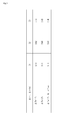
- Fig. 3 shows each of the superheat degrees of the control targets of the expansion valves 31 to 33 corresponding to evaporation ability ⁇ Te and heating ability ⁇ Tc.
- the main evaporator is a heat exchanger that an expansion valve whose control target is the superheat degree SH0 is provided at the inlet side.
- the expansion valve controlling the superheat degree is selected properly while the evaporation ability ⁇ Te is regarded as the difference between the outside air temperature Ta and the evaporation temperature Te.
- the control target of the first expansion valve 31 is switched from the superheat degree SH1 to the superheat degree SH0.
- the control target of the second expansion valve 32 is still the superheat degree SH2 and the control target of and the third expansion valve 33 is still the superheat degree SH3.
- the regulation of the opening degree of the first expansion valve 31 is mainly performed and the outdoor heat exchanger 11 functions as the main evaporator. Accordingly, for example in the state that wide heating ability is required, the outdoor heat exchanger 11 can be used as the main evaporator so as to deal with various heating demand.
- the control target of the second expansion valve 32 is switched from the superheat degree SH2 to the superheat degree SH0.
- the control target of the first expansion valve 31 is still the superheat degree SH1 and the control target of the third expansion valve 33 is still the superheat degree SH3.
- the regulation of the opening degree of the second expansion valve 32 is mainly performed.
- the waste heat collector 12 which performs the heat exchange with the engine waste heat can be used as the main evaporator, whereby the heating operation can be continued for long time.
- hysteresis ⁇ may be set with the threshold 5°C.
- the threshold is set to be 5- ⁇ °C when the expansion valve whose control target is the superheat degree SH0 is switched from the first expansion valve 31 to the second expansion valve 32, and is set to be 5+ ⁇ °C when the expansion valve is switched from the second expansion valve 32 to the first expansion valve 31.
- the control target of the third expansion valve 33 is switched from the superheat degree SH3 to the superheat degree SH0.
- the control target of the first expansion valve 31 is still the superheat degree SH1 and the control target of the second expansion valve is still the superheat degree SH2. In this case, when only the heat exchange with the outside air is performed, the superheat degree SH0 becomes too large.
- the opening degree of the third expansion valve 33 is regulated so that the coolant of the superheat degree SH2 lower than the superheat degree SH0 joins via the confluences J2 and J1, whereby the superheat degree SH0 is within the predetermined range. Accordingly, in the case that the evaporation ability is excessive only with the heat exchange with the outside air, the temperature of the suction superheat degree can be reduced with the supercooler 13, whereby the heating operation can be continued for long time.
- the state is supposable that the outside air temperature Ta is high and the operating unit number n of a plurality of the connected indoor units 71 is small so that the heating ability ⁇ Tc is very smaller than the evaporation ability ⁇ Te.
- the control target of the third expansion valve 33 is set to be the superheat degree SH0 and the temperature of the suction superheat degree is reduced with the coolant passing through the supercooler 13. Accordingly, in the state that the evaporation ability ⁇ Te is very larger than the heating ability ⁇ Tc, the excessive evaporation ability of the outdoor heat exchanger 11 can be suppressed with the supercooler 13, whereby the heating operation can be performed.
- the present invention is adoptable to an engine-driven heat pump.
Landscapes
- Engineering & Computer Science (AREA)
- Physics & Mathematics (AREA)
- Mechanical Engineering (AREA)
- Thermal Sciences (AREA)
- General Engineering & Computer Science (AREA)
- Chemical & Material Sciences (AREA)
- Combustion & Propulsion (AREA)
- Air Conditioning Control Device (AREA)
- Compression-Type Refrigeration Machines With Reversible Cycles (AREA)
Abstract
Description
- The present invention relates to a control art of a superheat degree at the time of heating operation of an engine-driven heat pump including an outdoor heat exchanger and a waste heat collection circuit connected in parallel with a suction route.
- There is well known an engine-driven heat pump including a compressor driven by an engine and a waste heat collector collecting engine waste heat to a coolant at the time of heating operation. In an engine-driven heat pump disclosed in the Japanese Patent Laid Open Gazette
2006-250438 - In the engine-driven heat pump disclosed in the Japanese Patent Laid Open Gazette
2006-250438 - The purpose of the present invention is to provide an engine-driven heat pump that an optimal main evaporator can be selected according to outside air temperature or heating load.
- An engine-driven heat pump according to the present invention that a waste heat collector is connected in parallel with an outdoor heat exchanger in the case that an outdoor heat exchanger functions as the evaporator, is characterized in that: a supercooler is connected in parallel with the outdoor heat exchanger and the waste heat collector in the case; a first expansion valve is provided at an outlet of the outdoor heat exchanger in the case so as to employ a superheat degree of the outlet as a control target; a second expansion valve is provided at an outlet of the waste heat collector in the case so as to employ a superheat degree of the outlet as a control target; a third expansion valve is provided at an outlet of the supercooler in the case so as to employ a superheat degree of the outlet as a control target; and a superheat degree in a compressor suction route at the downstream of a confluence of an outdoor heat exchanger outlet route, a waste heat collector outlet route and a supercooler outlet route in the case is employed as a suction superheat degree, the suction superheat degree is constructed to be able to be selected as the control target instead of the superheat degree of each of the first expansion valve, the second expansion valve and the third expansion valve, and the suction superheat degree is selected as the control target of the first expansion valve and the superheat degree at the outlet of each of the other two of the three expansion valves is employed as the control target of the corresponding valves.
- In engine-driven heat pump according to the present invention, preferably, in the case that outside air temperature is lower than predetermined temperature, the suction superheat degree is selected as the control target of the second expansion valve and the superheat degree at the outlet of each of the other two of the three expansion valves is employed as the control target of the corresponding valves.
- In engine-driven heat pump according to the present invention, preferably, in the case that heating load is lower than predetermined load, the suction superheat degree is selected as the control target of the third expansion valve and the superheat degree at the outlet of each of the other two of the three expansion valves is employed as the control target of the corresponding valves.
- According to the engine-driven heat pump of the present invention, the optimal main evaporator can be selected according to outside air temperature or heating load.
-
- [
Fig. 1 ] It is a coolant circuitry drawing of entire construction of an engine-driven heat pump according to the present invention. - [
Fig. 2 ] It is a block diagram of an ECU of the present invention. - [
Fig. 3 ] It is a table of superheat degrees of control target of each of expansion valves at the time of heating operation of the present invention. - Explanation will be given on construction of an engine-driven heat pump 1 according to the present invention referring
Fig. 1 .
The engine-driven heat pump 1 includes oneoutdoor unit 70 and a plurality ofindoor units 71. In below embodiment, for simplifying the explanation, theoutdoor unit 70 is supposed to be connected to oneindoor unit 71. - The engine-driven heat pump 1 is constructed so that a compressor 2 which is driven by an engine (not shown) so as to compress coolant, a four-
way valve 3 which switches connection of discharge side and suction side of the compressor 2 at the time of cooling operation and heating operation, anoutdoor heat exchanger 11, anindoor heat exchanger 15, afirst expansion valve 31 provided in a route connecting liquid piping sides of theoutdoor heat exchanger 11 and theindoor heat exchanger 15 to each other, and areceiver 6 in which liquid coolant condensed by theoutdoor heat exchanger 11 or theindoor heat exchanger 15 is pooled are connected.
At the time of cooling operation, the four-way valve 3 connects the discharge side of the compressor 2 to theoutdoor heat exchanger 11 and connects the suction side of the compressor 2 to theindoor heat exchanger 15 so that theoutdoor heat exchanger 11 and theindoor heat exchanger 15 function respectively as a condenser and an evaporator. At the time of heating operation, the four-way valve 3 connects the discharge side of the compressor 2 to theindoor heat exchanger 15 and connects the suction side of the compressor 2 to theoutdoor heat exchanger 11 so that theindoor heat exchanger 15 and theoutdoor heat exchanger 11 function respectively as the condenser and the evaporator. Thefirst expansion valve 31 is a flow regulating valve which controls the superheat degree of coolant sucked to the outlet of theoutdoor heat exchanger 11 in the case that theoutdoor heat exchanger 11 functions as the evaporator, that is, the compressor 2. - A
discharge route 20 connects the discharge side of the compressor 2 to the four-way valve 3. Thedischarge route 20 is provided therein with an oil separator 8 which separates refrigerating machine oil included in gas coolant and returns it to the suction side of the compressor 2. - A
suction route 21 connects the suction side of the compressor 2 to the four-way valve 3. Alow pressure sensor 55 and an outdoor heat exchangeoutlet temperature sensor 41 are provided in thesuction route 21. A wasteheat collection route 22 discussed later joins a confluence J1 of thesuction route 21. Asuction temperature sensor 40 is provided in a route from the confluence J1 to the suction side of the compressor 2. - The waste
heat collection route 22 is branched at the outlet of thereceiver 6 from the route connected to the liquid piping side of theoutdoor heat exchanger 11 and connected to thesuction route 21 in parallel with the route passing through theoutdoor heat exchanger 11. In the wasteheat collection route 22, asecond expansion valve 32 and awaste heat collector 12 are provided in this order along the route from the branch point from the route passing through theoutdoor heat exchanger 11 to the confluence J1 of thesuction route 21. An alternate long and two short dashes line passing through thewaste heat collector 12 indicates a flow of engine cooling water. Asupercooling route 23 discussed later joins a confluence J2 of the wasteheat collection route 22. A waste heat collectionoutlet temperature sensor 42 is provided between the outlet of thewaste heat collector 12 and the confluence J2. - The
supercooling route 23 is branched at the outlet of thereceiver 6 from the route passing through theoutdoor heat exchanger 11 and the wasteheat collection route 22, and is connected to thesuction route 21 in parallel with these routes. In thesupercooling route 23, athird expansion valve 33 and asupercooler 13 are provided in this order along the route from the branch point from the route passing through theoutdoor heat exchanger 11 etc. to the confluence J2 of the wasteheat collection route 22. A supercoolingoutlet temperature sensor 43 is provided between the outlet of thesupercooler 13 and the confluence J2. - Explanation will be given on coolant action in the coolant circuit construction at the time of heating operation.
At the time of heating operation, the four-way valve 3 connects thesuction route 21 to the outdoor heat exchanger 11 (seeFig. 1 ).
The gas coolant with high temperature and high pressure which is compressed and discharged by the compressor 2 is sent through the four-way valve 3 to theindoor heat exchanger 15, and the heat of the gas coolant is radiated to air in theindoor heat exchanger 15 dent by anindoor fan 62 so as to be condensed, whereby the heat of condensation is radiated to the air so as to warm it. At this time, the gas coolant turns into liquid coolant. Then, the liquid coolant flows into thereceiver 6 and reaches thefirst expansion valve 31 which functions as an outdoor heat exchange expansion valve, and is decompressed suddenly by thefirst expansion valve 31 so as to turn into gas-liquid mixture coolant which is easy to evaporate and then guided to theoutdoor heat exchanger 11. Theoutdoor heat exchanger 11 serves as an evaporator and the gas-liquid mixture coolant absorbs the heat of evaporation from the outside air so as to turn into gas coolant. Then, the gas coolant which evaporates via theoutdoor heat exchanger 11 passes along thesuction route 21 through the four-way valve 3 and is sucked and compressed by the compressor 2, and then is discharged again. - Herein, explanation will be given on the coolant action of the waste
heat collection route 22 and thesupercooling route 23 at the time of heating operation.
In the wasteheat collection route 22, the liquid coolant branched from thereceiver 6 is decompressed suddenly by thesecond expansion valve 32, which functions as a waste heat collection expansion valve, so as to turn into gas-liquid mixture coolant which is easy to evaporate, and then guided to thewaste heat collector 12. At this time, thewaste heat collector 12 also serves as an evaporator and the gas-liquid mixture coolant absorbs the heat of evaporation from the engine waste heat so as to turn into gas coolant. The gas coolant flows into thesuction route 21 at the confluence J1 and is sucked and compressed by the compressor 2, and then is discharged again.
On the other hand, in thesupercooling route 23, the liquid coolant branched from thereceiver 6 is decompressed suddenly by thethird expansion valve 33, which functions as a supercooling expansion valve, so as to turn into gas-liquid mixture coolant which is easy to evaporate, and then guided to thesupercooler 13 provided in thereceiver 6. Thesupercooler 13 also serves as an evaporator and the gas-liquid mixture coolant absorbs the heat of evaporation from the liquid coolant in thereceiver 6 so as to turn into gas coolant. The gas coolant flows into the wasteheat collection route 22 at the confluence J2 and flows into thesuction route 21 at the confluence J1 and is sucked and compressed by the compressor 2, and then is discharged again. - Explanation will be given on an electronic control unit (hereinafter, referred to as ECU) 10 referring
Fig. 2 .
The ECU 10 is constructed by connecting thelow pressure sensor 55, thesuction temperature sensor 40, the outdoor heat exchangeoutlet temperature sensor 41, the waste heat collectionoutlet temperature sensor 42, the supercoolingoutlet temperature sensor 43, and an outsideair temperature sensor 45 to thefirst expansion valve 31, thesecond expansion valve 32 and thethird expansion valve 33. - Explanation will be given on control construction of each of superheat degrees referring
Figs. 1 and2 .
An outdoor heat exchange superheat degree SH1 (hereinafter, referred to as superheat degree SH1), which is the superheat degree at the outlet of theoutdoor heat exchanger 11 at the time of heating operation, is found with the temperature difference between outdoor heat exchange outlet temperature T1 detected by the outdoor heat exchangeoutlet temperature sensor 41 and saturation equivalent temperature Te (hereinafter, referred to as evaporation temperature Te) of low pressure LP detected by thelow pressure sensor 55. The opening degree of thefirst expansion valve 31 is controlled for the aim that the temperature difference converges to a predetermined range. - A waste heat collection superheat degree SH2 (hereinafter, referred to as superheat degree SH2), which is the superheat degree at the outlet of the
waste heat collector 12 at the time of heating operation, is found with the temperature difference between waste heat collection outlet temperature T2 detected by the waste heat collectionoutlet temperature sensor 42 and the evaporation temperature Te. The opening degree of thesecond expansion valve 32 is controlled for the aim that the temperature difference converges to a predetermined range. - A supercooling superheat degree SH3 (hereinafter, referred to as superheat degree SH3), which is the superheat degree at the outlet of the
supercooler 13, is found with the temperature difference between supercooling outlet temperature T3 detected by the supercoolingoutlet temperature sensor 43 and the evaporation temperature Te. The opening degree of thethird expansion valve 33 is controlled for the aim that the temperature difference converges to a predetermined range. - A suction superheat degree SH0 (hereinafter, referred to as superheat degree SH0), which is the superheat degree from the confluence J1 to the suction side of the compressor 2, is found with the temperature difference between suction pipe temperature T0 detected by the
suction temperature sensor 40 and the evaporation temperature Te.
The suction superheat degree SH0 is the final superheat degree of the coolant sucked to the compressor 2. For preventing liquid compression of the compressor 2, the opening degree of each of thefirst expansion valve 31, thesecond expansion valve 32 and thethird expansion valve 33 must be regulated so as to make the superheat degree SH0 positive. In this embodiment, as discussed later, the control targets of the three kinds of expansion valves are substituted with the above-mentioned targets corresponding to evaporation ability or condensation ability so that the suction superheat degree SH0 is converged within the predetermined range as the control target.
In this embodiment, the opening degree of each of thefirst expansion valve 31, thesecond expansion valve 32 and thethird expansion valve 33 is controlled so that the suction superheat degree SH0 is converged to 5 to 8 deg. - Outside air temperature Ta is detected with the outside
air temperature sensor 45 provided in the vicinity of theoutdoor heat exchanger 11. - Explanation will be given on the control of each of the superheat degrees at the time of heating operation referring
Fig. 3. Fig. 3 shows each of the superheat degrees of the control targets of theexpansion valves 31 to 33 corresponding to evaporation ability Δ Te and heating ability ΔTc.
In this embodiment, corresponding to the outside air temperature Ta or heating demand determined by operating unit number n, operating time and arrangement position of theindoor units 71, that is, the heating ability ΔTc, one heat exchanger of theoutdoor heat exchanger 11, thewaste heat collector 12 and the outlet of thesupercooler 13 is selected as a main evaporator.
In this case, the main evaporator is a heat exchanger that an expansion valve whose control target is the superheat degree SH0 is provided at the inlet side.
In this embodiment, the expansion valve controlling the superheat degree is selected properly while the evaporation ability ΔTe is regarded as the difference between the outside air temperature Ta and the evaporation temperature Te. - When the evaporation ability ΔTe is not less than 5°C, the control target of the
first expansion valve 31 is switched from the superheat degree SH1 to the superheat degree SH0. On the other hand, the control target of thesecond expansion valve 32 is still the superheat degree SH2 and the control target of and thethird expansion valve 33 is still the superheat degree SH3. In this case, the regulation of the opening degree of thefirst expansion valve 31 is mainly performed and theoutdoor heat exchanger 11 functions as the main evaporator.
Accordingly, for example in the state that wide heating ability is required, theoutdoor heat exchanger 11 can be used as the main evaporator so as to deal with various heating demand. - When the evaporation ability ΔTe is less than 5°C, the control target of the
second expansion valve 32 is switched from the superheat degree SH2 to the superheat degree SH0. On the other hand, the control target of thefirst expansion valve 31 is still the superheat degree SH1 and the control target of thethird expansion valve 33 is still the superheat degree SH3. In this case, since the heat exchange with the outside air is difficult, the regulation of the opening degree of thesecond expansion valve 32 is mainly performed.
Accordingly, in the state that the outside air temperature Ta is low and so the evaporation ability ΔTe is low so that it is difficult to use theoutdoor heat exchanger 11 as the evaporator, thewaste heat collector 12 which performs the heat exchange with the engine waste heat can be used as the main evaporator, whereby the heating operation can be continued for long time. For preventing the expansion valve, which is regulated its opening degree to the superheat degree SH1 as the control target, from switching between thefirst expansion valve 31 and thesecond expansion valve 32, hysteresis α may be set with the threshold 5°C. Namely, the threshold is set to be 5-α°C when the expansion valve whose control target is the superheat degree SH0 is switched from thefirst expansion valve 31 to thesecond expansion valve 32, and is set to be 5+α°C when the expansion valve is switched from thesecond expansion valve 32 to thefirst expansion valve 31. - In the case that the evaporation ability ΔTe is very larger than the heating ability Δ Tc, for example in the case that the operating unit number n of the
indoor units 71 is not more than the predetermined number, the control target of thethird expansion valve 33 is switched from the superheat degree SH3 to the superheat degree SH0. On the other hand, the control target of thefirst expansion valve 31 is still the superheat degree SH1 and the control target of the second expansion valve is still the superheat degree SH2. In this case, when only the heat exchange with the outside air is performed, the superheat degree SH0 becomes too large. Then, The opening degree of thethird expansion valve 33 is regulated so that the coolant of the superheat degree SH2 lower than the superheat degree SH0 joins via the confluences J2 and J1, whereby the superheat degree SH0 is within the predetermined range.
Accordingly, in the case that the evaporation ability is excessive only with the heat exchange with the outside air, the temperature of the suction superheat degree can be reduced with thesupercooler 13, whereby the heating operation can be continued for long time. - Especially at the middle period such as spring and autumn, the state is supposable that the outside air temperature Ta is high and the operating unit number n of a plurality of the connected
indoor units 71 is small so that the heating ability ΔTc is very smaller than the evaporation ability ΔTe. In this state, the control target of thethird expansion valve 33 is set to be the superheat degree SH0 and the temperature of the suction superheat degree is reduced with the coolant passing through thesupercooler 13.
Accordingly, in the state that the evaporation ability ΔTe is very larger than the heating ability ΔTc, the excessive evaporation ability of theoutdoor heat exchanger 11 can be suppressed with thesupercooler 13, whereby the heating operation can be performed. - The present invention is adoptable to an engine-driven heat pump.
Claims (3)
- An engine-driven heat pump that a waste heat collector is connected in parallel with an outdoor heat exchanger in the case that an outdoor heat exchanger functions as the evaporator, characterized in that:a supercooler is connected in parallel with the outdoor heat exchanger and the waste heat collector in the case;a first expansion valve is provided at an outlet of the outdoor heat exchanger in the case so as to employ a superheat degree of the outlet as a control target;a second expansion valve is provided at an outlet of the waste heat collector in the case so as to employ a superheat degree of the outlet as a control target;a third expansion valve is provided at an outlet of the supercooler in the case so as to employ a superheat degree of the outlet as a control target; anda superheat degree in a compressor suction route at the downstream of a confluence of an outdoor heat exchanger outlet route, a waste heat collector outlet route and a supercooler outlet route in the case is employed as a suction superheat degree, the suction superheat degree is constructed to be able to be selected as the control target instead of the superheat degree of each of the first expansion valve, the second expansion valve and the third expansion valve, and the suction superheat degree is selected as the control target of the first expansion valve and the superheat degree at the outlet of each of the other two of the three expansion valves is employed as the control target of the corresponding valves.
- The engine-driven heat pump according to claim 1, wherein, in the case that outside air temperature is lower than predetermined temperature, the suction superheat degree is selected as the control target of the second expansion valve and the superheat degree at the outlet of each of the other two of the three expansion valves is employed as the control target of the corresponding valves.
- The engine-driven heat pump according to claim 1, wherein in the case that heating load is lower than predetermined load, the suction superheat degree is selected as the control target of the third expansion valve and the superheat degree at the outlet of each of the other two of the three expansion valves is employed as the control target of the corresponding valves.
Applications Claiming Priority (2)
| Application Number | Priority Date | Filing Date | Title |
|---|---|---|---|
| JP2008075775A JP5149663B2 (en) | 2008-03-24 | 2008-03-24 | Engine driven heat pump |
| PCT/JP2009/055617 WO2009119483A1 (en) | 2008-03-24 | 2009-03-23 | Engine-driven heat pump |
Publications (3)
| Publication Number | Publication Date |
|---|---|
| EP2275756A1 true EP2275756A1 (en) | 2011-01-19 |
| EP2275756A4 EP2275756A4 (en) | 2014-12-31 |
| EP2275756B1 EP2275756B1 (en) | 2019-06-19 |
Family
ID=41113676
Family Applications (1)
| Application Number | Title | Priority Date | Filing Date |
|---|---|---|---|
| EP09724252.3A Active EP2275756B1 (en) | 2008-03-24 | 2009-03-23 | Electronic control unit for an engine-driven heat pump |
Country Status (6)
| Country | Link |
|---|---|
| EP (1) | EP2275756B1 (en) |
| JP (1) | JP5149663B2 (en) |
| KR (1) | KR101131504B1 (en) |
| CN (1) | CN101960236B (en) |
| AU (1) | AU2009230171B2 (en) |
| WO (1) | WO2009119483A1 (en) |
Families Citing this family (2)
| Publication number | Priority date | Publication date | Assignee | Title |
|---|---|---|---|---|
| JP6335133B2 (en) * | 2015-03-17 | 2018-05-30 | ヤンマー株式会社 | heat pump |
| US10675948B2 (en) * | 2016-09-29 | 2020-06-09 | Bergstrom, Inc. | Systems and methods for controlling a vehicle HVAC system |
Family Cites Families (10)
| Publication number | Priority date | Publication date | Assignee | Title |
|---|---|---|---|---|
| JPH10170095A (en) * | 1996-12-10 | 1998-06-26 | Denso Corp | Engine driven heat pump device |
| JP2000035258A (en) * | 1998-07-16 | 2000-02-02 | Yanmar Diesel Engine Co Ltd | Engine heat pump |
| ATE329213T1 (en) * | 1999-02-17 | 2006-06-15 | Yanmar Co Ltd | CIRCUIT WITH REFRIGERANT SUBCOOLING |
| JP2003035467A (en) * | 2001-07-24 | 2003-02-07 | Sanyo Electric Co Ltd | Engine cooling device |
| JP4153763B2 (en) * | 2002-09-27 | 2008-09-24 | 東京瓦斯株式会社 | Gas heat pump type refrigeration apparatus and control method thereof |
| JP2004116930A (en) * | 2002-09-27 | 2004-04-15 | Tokyo Gas Co Ltd | Gas heat pump type air conditioner |
| JP3757967B2 (en) * | 2003-08-25 | 2006-03-22 | ダイキン工業株式会社 | Refrigeration equipment |
| JP4336619B2 (en) * | 2004-05-20 | 2009-09-30 | ヤンマー株式会社 | Engine heat pump |
| JP4549205B2 (en) * | 2005-03-10 | 2010-09-22 | ヤンマー株式会社 | Engine driven heat pump |
| JP4257351B2 (en) * | 2006-08-07 | 2009-04-22 | ヤンマー株式会社 | Engine driven heat pump |
-
2008
- 2008-03-24 JP JP2008075775A patent/JP5149663B2/en not_active Expired - Fee Related
-
2009
- 2009-03-23 WO PCT/JP2009/055617 patent/WO2009119483A1/en not_active Ceased
- 2009-03-23 KR KR1020107017633A patent/KR101131504B1/en not_active Expired - Fee Related
- 2009-03-23 CN CN2009801081959A patent/CN101960236B/en not_active Expired - Fee Related
- 2009-03-23 AU AU2009230171A patent/AU2009230171B2/en not_active Ceased
- 2009-03-23 EP EP09724252.3A patent/EP2275756B1/en active Active
Also Published As
| Publication number | Publication date |
|---|---|
| KR20100110866A (en) | 2010-10-13 |
| WO2009119483A1 (en) | 2009-10-01 |
| AU2009230171A1 (en) | 2009-10-01 |
| JP2009228997A (en) | 2009-10-08 |
| CN101960236A (en) | 2011-01-26 |
| CN101960236B (en) | 2013-04-17 |
| AU2009230171B2 (en) | 2012-02-02 |
| EP2275756A4 (en) | 2014-12-31 |
| KR101131504B1 (en) | 2012-04-04 |
| EP2275756B1 (en) | 2019-06-19 |
| JP5149663B2 (en) | 2013-02-20 |
Similar Documents
| Publication | Publication Date | Title |
|---|---|---|
| US7360372B2 (en) | Refrigeration system | |
| US9746212B2 (en) | Refrigerating and air-conditioning apparatus | |
| US7752864B2 (en) | Refrigeration apparatus | |
| US20100089082A1 (en) | Air conditioner | |
| AU2009248466B2 (en) | Refrigeration Apparatus | |
| EP2829821A2 (en) | Heat pump and flow path switching apparatus | |
| US7380411B2 (en) | Heat source unit with switching means between heating and cooling | |
| US20090282849A1 (en) | Refrigeration System | |
| EP2770276A1 (en) | Heat pump | |
| JP2012047409A (en) | Multi-type air conditioning system | |
| KR20210093560A (en) | Air Conditioner System for Simultaneous Cooling, Heating and hot water supplying and Control Method of the Same | |
| EP1431677A1 (en) | Air conditioner | |
| AU2005268121B2 (en) | Refrigerating apparatus | |
| JP2011196630A (en) | Multi-room type air conditioning device | |
| GB2533042A (en) | Air conditioner | |
| KR101923770B1 (en) | Engine drive type air conditioner | |
| JP2016205729A (en) | Refrigeration cycle device | |
| EP2275756B1 (en) | Electronic control unit for an engine-driven heat pump | |
| JP2018080883A (en) | Multi-room type air conditioner | |
| JP5463995B2 (en) | Multi-room air conditioner | |
| JP4549205B2 (en) | Engine driven heat pump | |
| CN115727447B (en) | Refrigerant circulation system, control method thereof and air conditioning equipment | |
| GB2533041A (en) | Air conditioner | |
| JP2006234321A (en) | Outdoor unit and air conditioner | |
| EP4328526A1 (en) | Heat pump system and control method thereof |
Legal Events
| Date | Code | Title | Description |
|---|---|---|---|
| PUAI | Public reference made under article 153(3) epc to a published international application that has entered the european phase |
Free format text: ORIGINAL CODE: 0009012 |
|
| 17P | Request for examination filed |
Effective date: 20101025 |
|
| AK | Designated contracting states |
Kind code of ref document: A1 Designated state(s): AT BE BG CH CY CZ DE DK EE ES FI FR GB GR HR HU IE IS IT LI LT LU LV MC MK MT NL NO PL PT RO SE SI SK TR |
|
| AX | Request for extension of the european patent |
Extension state: AL BA RS |
|
| DAX | Request for extension of the european patent (deleted) | ||
| A4 | Supplementary search report drawn up and despatched |
Effective date: 20141128 |
|
| RIC1 | Information provided on ipc code assigned before grant |
Ipc: F25B 13/00 20060101ALI20141124BHEP Ipc: F25B 27/00 20060101AFI20141124BHEP Ipc: F25B 27/02 20060101ALI20141124BHEP Ipc: F25B 1/00 20060101ALI20141124BHEP |
|
| STAA | Information on the status of an ep patent application or granted ep patent |
Free format text: STATUS: EXAMINATION IS IN PROGRESS |
|
| 17Q | First examination report despatched |
Effective date: 20161221 |
|
| GRAP | Despatch of communication of intention to grant a patent |
Free format text: ORIGINAL CODE: EPIDOSNIGR1 |
|
| STAA | Information on the status of an ep patent application or granted ep patent |
Free format text: STATUS: GRANT OF PATENT IS INTENDED |
|
| INTG | Intention to grant announced |
Effective date: 20190108 |
|
| GRAS | Grant fee paid |
Free format text: ORIGINAL CODE: EPIDOSNIGR3 |
|
| GRAA | (expected) grant |
Free format text: ORIGINAL CODE: 0009210 |
|
| STAA | Information on the status of an ep patent application or granted ep patent |
Free format text: STATUS: THE PATENT HAS BEEN GRANTED |
|
| AK | Designated contracting states |
Kind code of ref document: B1 Designated state(s): AT BE BG CH CY CZ DE DK EE ES FI FR GB GR HR HU IE IS IT LI LT LU LV MC MK MT NL NO PL PT RO SE SI SK TR |
|
| REG | Reference to a national code |
Ref country code: GB Ref legal event code: FG4D |
|
| RIN1 | Information on inventor provided before grant (corrected) |
Inventor name: SUGIMORI, KEIJI Inventor name: NARIYASU, HIROKI |
|
| REG | Reference to a national code |
Ref country code: CH Ref legal event code: EP |
|
| REG | Reference to a national code |
Ref country code: IE Ref legal event code: FG4D |
|
| RIN2 | Information on inventor provided after grant (corrected) |
Inventor name: SUGIMORI, KEIJI Inventor name: NARIYASU, HIROKI |
|
| REG | Reference to a national code |
Ref country code: DE Ref legal event code: R096 Ref document number: 602009058792 Country of ref document: DE |
|
| REG | Reference to a national code |
Ref country code: AT Ref legal event code: REF Ref document number: 1146039 Country of ref document: AT Kind code of ref document: T Effective date: 20190715 |
|
| REG | Reference to a national code |
Ref country code: NL Ref legal event code: MP Effective date: 20190619 |
|
| PG25 | Lapsed in a contracting state [announced via postgrant information from national office to epo] |
Ref country code: FI Free format text: LAPSE BECAUSE OF FAILURE TO SUBMIT A TRANSLATION OF THE DESCRIPTION OR TO PAY THE FEE WITHIN THE PRESCRIBED TIME-LIMIT Effective date: 20190619 Ref country code: NO Free format text: LAPSE BECAUSE OF FAILURE TO SUBMIT A TRANSLATION OF THE DESCRIPTION OR TO PAY THE FEE WITHIN THE PRESCRIBED TIME-LIMIT Effective date: 20190919 Ref country code: LT Free format text: LAPSE BECAUSE OF FAILURE TO SUBMIT A TRANSLATION OF THE DESCRIPTION OR TO PAY THE FEE WITHIN THE PRESCRIBED TIME-LIMIT Effective date: 20190619 Ref country code: HR Free format text: LAPSE BECAUSE OF FAILURE TO SUBMIT A TRANSLATION OF THE DESCRIPTION OR TO PAY THE FEE WITHIN THE PRESCRIBED TIME-LIMIT Effective date: 20190619 Ref country code: SE Free format text: LAPSE BECAUSE OF FAILURE TO SUBMIT A TRANSLATION OF THE DESCRIPTION OR TO PAY THE FEE WITHIN THE PRESCRIBED TIME-LIMIT Effective date: 20190619 |
|
| REG | Reference to a national code |
Ref country code: LT Ref legal event code: MG4D |
|
| PG25 | Lapsed in a contracting state [announced via postgrant information from national office to epo] |
Ref country code: GR Free format text: LAPSE BECAUSE OF FAILURE TO SUBMIT A TRANSLATION OF THE DESCRIPTION OR TO PAY THE FEE WITHIN THE PRESCRIBED TIME-LIMIT Effective date: 20190920 Ref country code: BG Free format text: LAPSE BECAUSE OF FAILURE TO SUBMIT A TRANSLATION OF THE DESCRIPTION OR TO PAY THE FEE WITHIN THE PRESCRIBED TIME-LIMIT Effective date: 20190919 Ref country code: LV Free format text: LAPSE BECAUSE OF FAILURE TO SUBMIT A TRANSLATION OF THE DESCRIPTION OR TO PAY THE FEE WITHIN THE PRESCRIBED TIME-LIMIT Effective date: 20190619 |
|
| REG | Reference to a national code |
Ref country code: AT Ref legal event code: MK05 Ref document number: 1146039 Country of ref document: AT Kind code of ref document: T Effective date: 20190619 |
|
| PG25 | Lapsed in a contracting state [announced via postgrant information from national office to epo] |
Ref country code: RO Free format text: LAPSE BECAUSE OF FAILURE TO SUBMIT A TRANSLATION OF THE DESCRIPTION OR TO PAY THE FEE WITHIN THE PRESCRIBED TIME-LIMIT Effective date: 20190619 Ref country code: CZ Free format text: LAPSE BECAUSE OF FAILURE TO SUBMIT A TRANSLATION OF THE DESCRIPTION OR TO PAY THE FEE WITHIN THE PRESCRIBED TIME-LIMIT Effective date: 20190619 Ref country code: SK Free format text: LAPSE BECAUSE OF FAILURE TO SUBMIT A TRANSLATION OF THE DESCRIPTION OR TO PAY THE FEE WITHIN THE PRESCRIBED TIME-LIMIT Effective date: 20190619 Ref country code: NL Free format text: LAPSE BECAUSE OF FAILURE TO SUBMIT A TRANSLATION OF THE DESCRIPTION OR TO PAY THE FEE WITHIN THE PRESCRIBED TIME-LIMIT Effective date: 20190619 Ref country code: AT Free format text: LAPSE BECAUSE OF FAILURE TO SUBMIT A TRANSLATION OF THE DESCRIPTION OR TO PAY THE FEE WITHIN THE PRESCRIBED TIME-LIMIT Effective date: 20190619 Ref country code: PT Free format text: LAPSE BECAUSE OF FAILURE TO SUBMIT A TRANSLATION OF THE DESCRIPTION OR TO PAY THE FEE WITHIN THE PRESCRIBED TIME-LIMIT Effective date: 20191021 Ref country code: EE Free format text: LAPSE BECAUSE OF FAILURE TO SUBMIT A TRANSLATION OF THE DESCRIPTION OR TO PAY THE FEE WITHIN THE PRESCRIBED TIME-LIMIT Effective date: 20190619 |
|
| PG25 | Lapsed in a contracting state [announced via postgrant information from national office to epo] |
Ref country code: ES Free format text: LAPSE BECAUSE OF FAILURE TO SUBMIT A TRANSLATION OF THE DESCRIPTION OR TO PAY THE FEE WITHIN THE PRESCRIBED TIME-LIMIT Effective date: 20190619 Ref country code: IS Free format text: LAPSE BECAUSE OF FAILURE TO SUBMIT A TRANSLATION OF THE DESCRIPTION OR TO PAY THE FEE WITHIN THE PRESCRIBED TIME-LIMIT Effective date: 20191019 |
|
| PG25 | Lapsed in a contracting state [announced via postgrant information from national office to epo] |
Ref country code: TR Free format text: LAPSE BECAUSE OF FAILURE TO SUBMIT A TRANSLATION OF THE DESCRIPTION OR TO PAY THE FEE WITHIN THE PRESCRIBED TIME-LIMIT Effective date: 20190619 |
|
| PG25 | Lapsed in a contracting state [announced via postgrant information from national office to epo] |
Ref country code: PL Free format text: LAPSE BECAUSE OF FAILURE TO SUBMIT A TRANSLATION OF THE DESCRIPTION OR TO PAY THE FEE WITHIN THE PRESCRIBED TIME-LIMIT Effective date: 20190619 Ref country code: DK Free format text: LAPSE BECAUSE OF FAILURE TO SUBMIT A TRANSLATION OF THE DESCRIPTION OR TO PAY THE FEE WITHIN THE PRESCRIBED TIME-LIMIT Effective date: 20190619 |
|
| PGFP | Annual fee paid to national office [announced via postgrant information from national office to epo] |
Ref country code: GB Payment date: 20200323 Year of fee payment: 12 |
|
| PG25 | Lapsed in a contracting state [announced via postgrant information from national office to epo] |
Ref country code: IS Free format text: LAPSE BECAUSE OF FAILURE TO SUBMIT A TRANSLATION OF THE DESCRIPTION OR TO PAY THE FEE WITHIN THE PRESCRIBED TIME-LIMIT Effective date: 20200224 |
|
| REG | Reference to a national code |
Ref country code: DE Ref legal event code: R097 Ref document number: 602009058792 Country of ref document: DE |
|
| PLBE | No opposition filed within time limit |
Free format text: ORIGINAL CODE: 0009261 |
|
| STAA | Information on the status of an ep patent application or granted ep patent |
Free format text: STATUS: NO OPPOSITION FILED WITHIN TIME LIMIT |
|
| PG2D | Information on lapse in contracting state deleted |
Ref country code: IS |
|
| PGFP | Annual fee paid to national office [announced via postgrant information from national office to epo] |
Ref country code: DE Payment date: 20200331 Year of fee payment: 12 |
|
| 26N | No opposition filed |
Effective date: 20200603 |
|
| PG25 | Lapsed in a contracting state [announced via postgrant information from national office to epo] |
Ref country code: SI Free format text: LAPSE BECAUSE OF FAILURE TO SUBMIT A TRANSLATION OF THE DESCRIPTION OR TO PAY THE FEE WITHIN THE PRESCRIBED TIME-LIMIT Effective date: 20190619 |
|
| PGFP | Annual fee paid to national office [announced via postgrant information from national office to epo] |
Ref country code: IT Payment date: 20200318 Year of fee payment: 12 |
|
| REG | Reference to a national code |
Ref country code: DE Ref legal event code: R082 Ref document number: 602009058792 Country of ref document: DE Representative=s name: JOSTARNDT PATENTANWALTS-AG, DE Ref country code: DE Ref legal event code: R081 Ref document number: 602009058792 Country of ref document: DE Owner name: YANMAR POWER TECHNOLOGY CO., LTD., JP Free format text: FORMER OWNER: YANMAR CO., LTD., OSAKA, JP |
|
| PG25 | Lapsed in a contracting state [announced via postgrant information from national office to epo] |
Ref country code: MC Free format text: LAPSE BECAUSE OF FAILURE TO SUBMIT A TRANSLATION OF THE DESCRIPTION OR TO PAY THE FEE WITHIN THE PRESCRIBED TIME-LIMIT Effective date: 20190619 |
|
| REG | Reference to a national code |
Ref country code: CH Ref legal event code: PL |
|
| REG | Reference to a national code |
Ref country code: BE Ref legal event code: MM Effective date: 20200331 |
|
| PG25 | Lapsed in a contracting state [announced via postgrant information from national office to epo] |
Ref country code: LU Free format text: LAPSE BECAUSE OF NON-PAYMENT OF DUE FEES Effective date: 20200323 |
|
| PG25 | Lapsed in a contracting state [announced via postgrant information from national office to epo] |
Ref country code: LI Free format text: LAPSE BECAUSE OF NON-PAYMENT OF DUE FEES Effective date: 20200331 Ref country code: IE Free format text: LAPSE BECAUSE OF NON-PAYMENT OF DUE FEES Effective date: 20200323 Ref country code: CH Free format text: LAPSE BECAUSE OF NON-PAYMENT OF DUE FEES Effective date: 20200331 Ref country code: FR Free format text: LAPSE BECAUSE OF NON-PAYMENT OF DUE FEES Effective date: 20200331 |
|
| PG25 | Lapsed in a contracting state [announced via postgrant information from national office to epo] |
Ref country code: BE Free format text: LAPSE BECAUSE OF NON-PAYMENT OF DUE FEES Effective date: 20200331 |
|
| REG | Reference to a national code |
Ref country code: DE Ref legal event code: R119 Ref document number: 602009058792 Country of ref document: DE |
|
| GBPC | Gb: european patent ceased through non-payment of renewal fee |
Effective date: 20210323 |
|
| PG25 | Lapsed in a contracting state [announced via postgrant information from national office to epo] |
Ref country code: GB Free format text: LAPSE BECAUSE OF NON-PAYMENT OF DUE FEES Effective date: 20210323 Ref country code: DE Free format text: LAPSE BECAUSE OF NON-PAYMENT OF DUE FEES Effective date: 20211001 |
|
| PG25 | Lapsed in a contracting state [announced via postgrant information from national office to epo] |
Ref country code: IT Free format text: LAPSE BECAUSE OF NON-PAYMENT OF DUE FEES Effective date: 20210323 |
|
| PG25 | Lapsed in a contracting state [announced via postgrant information from national office to epo] |
Ref country code: MT Free format text: LAPSE BECAUSE OF FAILURE TO SUBMIT A TRANSLATION OF THE DESCRIPTION OR TO PAY THE FEE WITHIN THE PRESCRIBED TIME-LIMIT Effective date: 20190619 Ref country code: CY Free format text: LAPSE BECAUSE OF FAILURE TO SUBMIT A TRANSLATION OF THE DESCRIPTION OR TO PAY THE FEE WITHIN THE PRESCRIBED TIME-LIMIT Effective date: 20190619 |
|
| PG25 | Lapsed in a contracting state [announced via postgrant information from national office to epo] |
Ref country code: MK Free format text: LAPSE BECAUSE OF FAILURE TO SUBMIT A TRANSLATION OF THE DESCRIPTION OR TO PAY THE FEE WITHIN THE PRESCRIBED TIME-LIMIT Effective date: 20190619 |