EP2275710B1 - Control device of and control method for vehicle continuously variable transmission - Google Patents
Control device of and control method for vehicle continuously variable transmission Download PDFInfo
- Publication number
- EP2275710B1 EP2275710B1 EP10169446A EP10169446A EP2275710B1 EP 2275710 B1 EP2275710 B1 EP 2275710B1 EP 10169446 A EP10169446 A EP 10169446A EP 10169446 A EP10169446 A EP 10169446A EP 2275710 B1 EP2275710 B1 EP 2275710B1
- Authority
- EP
- European Patent Office
- Prior art keywords
- gear position
- subtransmission mechanism
- speed
- continuously variable
- speed ratio
- Prior art date
- Legal status (The legal status is an assumption and is not a legal conclusion. Google has not performed a legal analysis and makes no representation as to the accuracy of the status listed.)
- Active
Links
Images


Classifications
-
- F—MECHANICAL ENGINEERING; LIGHTING; HEATING; WEAPONS; BLASTING
- F16—ENGINEERING ELEMENTS AND UNITS; GENERAL MEASURES FOR PRODUCING AND MAINTAINING EFFECTIVE FUNCTIONING OF MACHINES OR INSTALLATIONS; THERMAL INSULATION IN GENERAL
- F16H—GEARING
- F16H61/00—Control functions within control units of change-speed- or reversing-gearings for conveying rotary motion ; Control of exclusively fluid gearing, friction gearing, gearings with endless flexible members or other particular types of gearing
- F16H61/66—Control functions within control units of change-speed- or reversing-gearings for conveying rotary motion ; Control of exclusively fluid gearing, friction gearing, gearings with endless flexible members or other particular types of gearing specially adapted for continuously variable gearings
- F16H61/662—Control functions within control units of change-speed- or reversing-gearings for conveying rotary motion ; Control of exclusively fluid gearing, friction gearing, gearings with endless flexible members or other particular types of gearing specially adapted for continuously variable gearings with endless flexible members
- F16H61/66254—Control functions within control units of change-speed- or reversing-gearings for conveying rotary motion ; Control of exclusively fluid gearing, friction gearing, gearings with endless flexible members or other particular types of gearing specially adapted for continuously variable gearings with endless flexible members controlling of shifting being influenced by a signal derived from the engine and the main coupling
- F16H61/66259—Control functions within control units of change-speed- or reversing-gearings for conveying rotary motion ; Control of exclusively fluid gearing, friction gearing, gearings with endless flexible members or other particular types of gearing specially adapted for continuously variable gearings with endless flexible members controlling of shifting being influenced by a signal derived from the engine and the main coupling using electrical or electronical sensing or control means
-
- F—MECHANICAL ENGINEERING; LIGHTING; HEATING; WEAPONS; BLASTING
- F16—ENGINEERING ELEMENTS AND UNITS; GENERAL MEASURES FOR PRODUCING AND MAINTAINING EFFECTIVE FUNCTIONING OF MACHINES OR INSTALLATIONS; THERMAL INSULATION IN GENERAL
- F16H—GEARING
- F16H37/00—Combinations of mechanical gearings, not provided for in groups F16H1/00 - F16H35/00
- F16H37/02—Combinations of mechanical gearings, not provided for in groups F16H1/00 - F16H35/00 comprising essentially only toothed or friction gearings
- F16H37/021—Combinations of mechanical gearings, not provided for in groups F16H1/00 - F16H35/00 comprising essentially only toothed or friction gearings toothed gearing combined with continuously variable friction gearing
- F16H37/022—Combinations of mechanical gearings, not provided for in groups F16H1/00 - F16H35/00 comprising essentially only toothed or friction gearings toothed gearing combined with continuously variable friction gearing the toothed gearing having orbital motion
-
- F—MECHANICAL ENGINEERING; LIGHTING; HEATING; WEAPONS; BLASTING
- F16—ENGINEERING ELEMENTS AND UNITS; GENERAL MEASURES FOR PRODUCING AND MAINTAINING EFFECTIVE FUNCTIONING OF MACHINES OR INSTALLATIONS; THERMAL INSULATION IN GENERAL
- F16H—GEARING
- F16H61/00—Control functions within control units of change-speed- or reversing-gearings for conveying rotary motion ; Control of exclusively fluid gearing, friction gearing, gearings with endless flexible members or other particular types of gearing
- F16H61/04—Smoothing ratio shift
- F16H61/06—Smoothing ratio shift by controlling rate of change of fluid pressure
- F16H61/061—Smoothing ratio shift by controlling rate of change of fluid pressure using electric control means
-
- F—MECHANICAL ENGINEERING; LIGHTING; HEATING; WEAPONS; BLASTING
- F16—ENGINEERING ELEMENTS AND UNITS; GENERAL MEASURES FOR PRODUCING AND MAINTAINING EFFECTIVE FUNCTIONING OF MACHINES OR INSTALLATIONS; THERMAL INSULATION IN GENERAL
- F16H—GEARING
- F16H61/00—Control functions within control units of change-speed- or reversing-gearings for conveying rotary motion ; Control of exclusively fluid gearing, friction gearing, gearings with endless flexible members or other particular types of gearing
- F16H61/66—Control functions within control units of change-speed- or reversing-gearings for conveying rotary motion ; Control of exclusively fluid gearing, friction gearing, gearings with endless flexible members or other particular types of gearing specially adapted for continuously variable gearings
- F16H61/664—Friction gearings
- F16H61/6648—Friction gearings controlling of shifting being influenced by a signal derived from the engine and the main coupling
-
- F—MECHANICAL ENGINEERING; LIGHTING; HEATING; WEAPONS; BLASTING
- F16—ENGINEERING ELEMENTS AND UNITS; GENERAL MEASURES FOR PRODUCING AND MAINTAINING EFFECTIVE FUNCTIONING OF MACHINES OR INSTALLATIONS; THERMAL INSULATION IN GENERAL
- F16H—GEARING
- F16H61/00—Control functions within control units of change-speed- or reversing-gearings for conveying rotary motion ; Control of exclusively fluid gearing, friction gearing, gearings with endless flexible members or other particular types of gearing
- F16H61/70—Control functions within control units of change-speed- or reversing-gearings for conveying rotary motion ; Control of exclusively fluid gearing, friction gearing, gearings with endless flexible members or other particular types of gearing specially adapted for change-speed gearing in group arrangement, i.e. with separate change-speed gear trains arranged in series, e.g. range or overdrive-type gearing arrangements
- F16H61/702—Control functions within control units of change-speed- or reversing-gearings for conveying rotary motion ; Control of exclusively fluid gearing, friction gearing, gearings with endless flexible members or other particular types of gearing specially adapted for change-speed gearing in group arrangement, i.e. with separate change-speed gear trains arranged in series, e.g. range or overdrive-type gearing arrangements using electric or electrohydraulic control means
-
- F—MECHANICAL ENGINEERING; LIGHTING; HEATING; WEAPONS; BLASTING
- F16—ENGINEERING ELEMENTS AND UNITS; GENERAL MEASURES FOR PRODUCING AND MAINTAINING EFFECTIVE FUNCTIONING OF MACHINES OR INSTALLATIONS; THERMAL INSULATION IN GENERAL
- F16H—GEARING
- F16H37/00—Combinations of mechanical gearings, not provided for in groups F16H1/00 - F16H35/00
- F16H37/02—Combinations of mechanical gearings, not provided for in groups F16H1/00 - F16H35/00 comprising essentially only toothed or friction gearings
- F16H37/021—Combinations of mechanical gearings, not provided for in groups F16H1/00 - F16H35/00 comprising essentially only toothed or friction gearings toothed gearing combined with continuously variable friction gearing
- F16H2037/023—Combinations of mechanical gearings, not provided for in groups F16H1/00 - F16H35/00 comprising essentially only toothed or friction gearings toothed gearing combined with continuously variable friction gearing the combined gearing being provided with at least two forward and one reverse ratio in a serially arranged sub-transmission
-
- F—MECHANICAL ENGINEERING; LIGHTING; HEATING; WEAPONS; BLASTING
- F16—ENGINEERING ELEMENTS AND UNITS; GENERAL MEASURES FOR PRODUCING AND MAINTAINING EFFECTIVE FUNCTIONING OF MACHINES OR INSTALLATIONS; THERMAL INSULATION IN GENERAL
- F16H—GEARING
- F16H2200/00—Transmissions for multiple ratios
- F16H2200/20—Transmissions using gears with orbital motion
- F16H2200/203—Transmissions using gears with orbital motion characterised by the engaging friction means not of the freewheel type, e.g. friction clutches or brakes
Definitions
- This invention relates to control device of and a control method for a vehicle continuously variable transmission.
- JPH5-79554A which constitutes the closest prior art, published by the Japan Patent Office in 2002, discloses a control device for a vehicle continuously variable transmission that includes, in addition to a continuously variable transmission mechanism, a subtransmission mechanism which can be switched between a plurality of gear positions, in which the continuously variable transmission mechanism is downshifted when the gear position of the subtransmission mechanism is upshifted.
- JP 2004 125106 A a speed change control method for an automatic transmission is described which is capable of reducing a shift shock, in particular a shift shock occurring during a power-off upshift.
- JP 62 137239 A and EP 0 217 221 A2 disclose a method and apparatus for controlling a power transmitting system for an automotive vehicle, including a continuously variable transmission (CVT) and an auxiliary transmission which is connected to the CVT and which is automatically shifted from one of two or more forward drive positions to the other depending upon operating conditions of the vehicle.
- CVT continuously variable transmission
- auxiliary transmission which is connected to the CVT and which is automatically shifted from one of two or more forward drive positions to the other depending upon operating conditions of the vehicle.
- this invention is a control device, claimed in claim 1, and a control method, claimed in claim 3, for a vehicle continuously variable transmission comprising: a continuously variable transmission mechanism having a speed ratio that can be modified continuously; and a subtransmission mechanism that is provided in series with the continuously variable transmission mechanism, includes a first gear position and a second gear position, the second gear position having a smaller speed ratio than the first gear position, as forward gear positions, and switches between the first gear position and the second gear position by engaging or disengaging a plurality of frictional engagement elements selectively, wherein an instruction relating to inertia phase processing, which is implemented during a process for modifying the gear position of the subtransmission mechanism from the first gear position to the second gear position when a torque input into the vehicle continuously variable transmission is negative torque to adjust an input rotation variation speed of the subtransmission mechanism by controlling an engagement capacity of the frictional engagement elements of the subtransmission mechanism, is completed before an input rotation speed of the subtransmission mechanism actually reaches an input rotation speed of the second gear position; and
- FIG. 1 is a schematic diagram showing the constitution of a vehicle installed with a continuously variable transmission according to an embodiment of this invention.
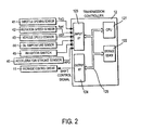
- FIG. 2 is a view showing the internal constitution of a transmission controller according to this embodiment of this invention.
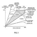
- FIG. 3 is a view showing an example of a shift map of the transmission according to this embodiment of this invention.
- FIG. 4 is a flowchart showing the content of a shift control program according to this embodiment of this invention, which is executed by the transmission controller.
- FIGs. 5A-5G are time charts illustrating a mode switch shift control operation performed during a power OFF upshift according to this embodiment of this invention.
- FIGs. 6A-6G are time charts illustrating a mode switch shift control operation performed during a power OFF upshift according to a comparative example.
- a “speed ratio” of a certain transmission mechanism is a value obtained by dividing an input rotation speed of the transmission mechanism by an output rotation speed of the transmission mechanism. Further, a “Lowest speed ratio” denotes a maximum speed ratio of the transmission mechanism, and a “Highest speed ratio” denotes a minimum speed ratio of the transmission mechanism.
- FIG. 1 is a schematic constitutional diagram of a vehicle installed with a continuously variable transmission according to an embodiment of this invention.
- the vehicle has an internal combustion engine 1 as a power source. Output rotation of the engine 1 is transmitted to a drive wheel 7 via a torque converter having a lockup clutch 2, a first gear train 3, a continuously variable transmission (to be referred to as a "transmission 4" hereafter), a second gear train 5, and a final reduction gear 6.
- the second gear train 5 is provided with a parking mechanism 8 which locks an output shaft of the transmission 4 mechanically so that the output shaft is incapable of rotation during parking.
- the vehicle is further provided with an oil pump 10 which is driven using a part of the power of the engine 1, a hydraulic control circuit 11 which regulates an oil pressure from the oil pump 10 and supplies the regulated oil pressure to various sites of the transmission 4, and a transmission controller 12 which controls the hydraulic control circuit 11.
- the hydraulic control circuit 11 and the transmission controller 12 together constitute shift control means.
- the transmission 4 includes a belt type continuously variable transmission mechanism (to be referred to as a "variator 20" hereafter), and a subtransmission mechanism 30 provided to the rear of and in series with the variator 20.
- the term “provided to the rear of” means that the subtransmission mechanism 30 is provided further toward the drive wheel 7 side than the variator 20 on a power transmission path extending from the engine 1 to the drive wheel 7.
- the term “provided in series” means that the variator 20 and the subtransmission mechanism 30 are provided in series on this power transmission path.
- the subtransmission mechanism 30 may be directly connected to an output shaft of the variator 20, as in this example, or via another transmission mechanism or power transmission mechanism (for example, a gear train).
- the variator 20 includes a primary pulley 21, a secondary pulley 22, and a V belt 23 wrapped around the pulleys 21, 22.
- the pulleys 21, 22 respectively include a fixed conical plate, a movable conical plate that is disposed relative to the fixed conical plate such that respective sheave surfaces thereof oppose each other and forms a V groove with the fixed conical plate, and a hydraulic cylinder 23a, 23b that is provided on a back surface of the movable conical plate and displaces the movable conical plate in an axial direction.
- the subtransmission mechanism 30 is a two-forward speed, one-reverse speed transmission mechanism.
- the subtransmission mechanism 30 includes a Ravigneaux planetary gear mechanism 31 coupling the carriers of two planetary gear sets, and a plurality of frictional engagement elements (a Low brake 32, a High clutch 33, and a Rev brake 34) connected to a plurality of rotary elements constituting the Ravigneaux planetary gear mechanism 31 to modify the rotation states thereof.
- the gear position of the subtransmission mechanism 30 is changed by adjusting the oil pressure supplied to the respective frictional engagement elements 32 to 34 such that the engagement/disengagement states of the respective frictional engagement elements 32 to 34 are modified.
- the gear position of the subtransmission mechanism 30 is set in a first speed.
- the gear position of the subtransmission mechanism 30 is set in a second speed having a smaller speed ratio than the first speed.
- the gear position of the subtransmission mechanism 30 is set in reverse.
- the transmission controller 12 is constituted by a CPU 121, a storage device 122 including a RAM and a ROM, an input interface 123, an output interface 124, and a bus 125 connecting these components to each other.
- Output signals and the like are input into the input interface 123 from a throttle opening sensor 41, a rotation speed sensor 42, a vehicle speed sensor 43, an oil temperature sensor 44, an inhibitor switch 45, and an accelerator stroke sensor 46.
- the throttle opening sensor 41 detects an opening (to be referred to hereafter as a "throttle opening") TVO of a throttle valve of the engine 1.
- the vehicle speed sensor 43 detects a travel speed (to be referred to hereafter as a "vehicle speed") VSP of the vehicle.
- the oil temperature sensor 44 detects an oil temperature of the transmission 4.
- the inhibitor switch 45 detects a position of a select lever provided in the vehicle.
- the accelerator stroke sensor 46 detects a depression amount APO of an accelerator pedal.
- the storage device 122 stores a shift control program for the transmission 4 and a shift map ( FIG. 4 ) used by the shift control program.
- the CPU 121 reads and executes the shift control program stored in the storage device 122, generates a shift control signal by implementing various types of calculation processing on the various signals input via the input interface 123, and outputs the generated shift control signal to the hydraulic control circuit 11 via the output interface 124.
- Various values used in the calculation processing executed by the CPU 121 and calculation results thereof are stored in the storage device 122 as appropriate.
- the hydraulic control circuit 11 is constituted by a plurality of flow passages and a plurality of hydraulic control valves.
- the hydraulic control circuit 11 controls the plurality of hydraulic control valves on the basis of the shift control signal from the transmission controller 12 to switch an oil pressure supply path, and prepares a required oil pressure from the oil pressure generated by the oil pump 10, which is then supplied to various sites of the transmission 4.
- the speed ratio vRatio of the variator 20 is modified and the gear position of the subtransmission mechanism 30 is changed, whereby a shift is performed in the transmission 4.
- FIG. 3 shows an example of the shift map stored in the storage device 122 of the transmission controller 12.
- an operating point of the transmission 4 is determined on the basis of the vehicle speed VSP and the primary rotation speed Npri.
- An incline of a line linking the operating point of the transmission 4 and a zero point in the lower left corner of the shift map indicates the speed ratio of the transmission 4 (an overall speed ratio obtained by multiplying the speed ratio of the subtransmission mechanism 30 with the speed ratio vRatio of the variator 20, to be referred to hereafter as a "through speed ratio Ratio").
- the transmission 4 When the transmission 4 is in the low speed mode, the transmission 4 can be shifted between a low speed mode Lowest line, which is obtained by maximizing the speed ratio vRatio of the variator 20, and a low speed mode Highest line, which is obtained by minimizing the speed ratio vRatio of the variator 20.
- the operating point of the transmission 4 moves within an A region and a B region.
- the transmission 4 When the transmission 4 is in the high speed mode, the transmission 4 can be shifted between a high speed mode Lowest line, which is obtained by maximizing the speed ratio vRatio of the variator 20, and a high speed mode Highest line, which is obtained by minimizing the speed ratio vRatio of the variator 20.
- the high speed mode the operating point of the transmission 4 moves within the B region and a C region.
- the speed ratios of the respective gear positions of the subtransmission mechanism 30 are set such that a speed ratio corresponding to the low speed mode Highest line (low speed mode Highest speed ratio) is smaller than a speed ratio corresponding to the high speed mode Lowest line (high speed mode Lowest speed ratio).
- a low speed mode ratio range which is the through speed ratio Ratio range of the transmission 4 in the low speed mode
- a high speed mode ratio range which is the through speed ratio Ratio range of the transmission 4 in the high speed mode
- a mode switch shift line (a 1-2 shift line of the subtransmission mechanism 30) at which the subtransmission mechanism 30 performs a shift is set on the shift map to overlap the low speed mode Highest line.
- a through speed ratio corresponding to the mode switch shift line (to be referred to hereafter as a "mode switch speed ratio”) mRatio is set at an equal value to the low speed mode Highest speed ratio.
- the transmission controller 12 performs a shift in the subtransmission mechanism 30 and modifies a speed ratio vRatio of the variator 20 in an opposite direction to a variation direction of the speed ratio of the subtransmission mechanism 30.
- the transmission controller 12 modifies the gear position of the subtransmission mechanism 30 from the first speed to the second speed (a subtransmission mechanism 1-2 shift) and modifies the speed ratio vRatio of the variator 20 to a large speed ratio side.
- the transmission controller 12 modifies the gear position of the subtransmission mechanism 30 from the second speed to the first speed (a subtransmission mechanism 2-1 shift) and modifies the speed ratio vRatio of the variator 20 to a small speed ratio side.
- the reason for causing the speed ratio vRatio of the variator 20 to vary in the opposite direction to the speed ratio variation direction of the subtransmission mechanism 30 during a mode switch shift is to ensure that input rotation variation due to a step occurring in the through speed ratio Ratio of the transmission 4 does not cause the driver to experience an unpleasant sensation.
- shifts performed by the transmission 4 include shifts performed in a power ON state and shifts performed in a power OFF state.
- a shift performed in the power ON state is an upshift or a downshift performed when the accelerator pedal is depressed, or in other words when the input torque of the transmission 4 is positive torque (torque at which an input side of the transmission 4 shifts to a drive side).
- a shift performed in the power OFF state is an upshift or a downshift performed when the accelerator pedal is not depressed, or in other words when the input torque of the transmission 4 is negative torque (torque at which an output side of the transmission 4 shifts to the drive side).
- An object of this embodiment is to improve drivability when a mode switch shift is performed during an upshift in the power OFF state (to be referred to hereafter as a "power OFF upshift"), from among the four types of shifts described above.
- Mode switch shift control executed during a power OFF upshift according to this embodiment will be described below after describing problems that arise when the mode switch shift control according to this embodiment is not implemented.
- FIGs. 6A-6G are time charts of a comparative example illustrating the problems that arise when the mode switch shift control according to this embodiment is not implemented.
- the subtransmission mechanism 30 achieves a switch from the low speed mode to the high speed mode by performing preparatory phase processing, inertia phase processing, and torque phase processing.
- the preparatory phase processing is processing for preparing to modify the gear position of the subtransmission mechanism 30. More specifically, in the preparatory phase processing, a command oil pressure of a disengagement side frictional engagement element of the subtransmission mechanism 30 is reduced to an initial disengagement pressure (a pressure at which the disengagement side frictional engagement element begins to slide), and a command oil pressure of an engagement side frictional engagement element is held at a precharge pressure for a predetermined time and then lowered to an initial engagement pressure (a pressure at which torque can be transmitted by the engagement side frictional engagement element).
- an initial disengagement pressure a pressure at which the disengagement side frictional engagement element begins to slide
- a command oil pressure of an engagement side frictional engagement element is held at a precharge pressure for a predetermined time and then lowered to an initial engagement pressure (a pressure at which torque can be transmitted by the engagement side frictional engagement element).
- the inertia phase processing is processing for shifting an input rotation speed of the subtransmission mechanism 30 from a pre-shift rotation speed to a post-shift rotation speed. More specifically, in the inertia phase processing, an input rotation variation speed of the subtransmission mechanism 30 is adjusted by controlling the oil pressure of the disengagement side frictional engagement element to increase or decrease an engagement capacity thereof such that the input rotation speed of the subtransmission mechanism 30 is reduced by a desired proportion.
- the torque phase processing is processing for shifting reception of the input torque of the subtransmission mechanism 30 from the disengagement side frictional engagement element to the engagement side frictional engagement element. More specifically, in the torque phase processing, the oil pressure of the disengagement side frictional engagement element is reduced toward zero while the oil pressure of the engagement side frictional engagement element is increased from the initial engagement pressure (the engagement capacity thereof is increased).
- the speed ratio of the subtransmission mechanism 30 is gradually modified to the small speed ratio side, and in accordance therewith, the speed ratio vRatio of the variator 20 is modified to the large speed ratio side ( FIG. 6D, FIG. 6E ).
- the speed ratio vRatio of the variator 20 is gradually modified to the large speed ratio side, engine braking increases, and as a result, a deceleration/acceleration i of the vehicle increases ( FIG. 6D ).
- the inertia phase processing is implemented before the torque phase processing. Therefore, during the inertia phase processing, torque is transmitted by the disengagement side (first speed side) frictional engagement element of the subtransmission mechanism 30, and as a result, engine brake application increases.
- the inertia phase processing ends when the input rotation speed of the subtransmission mechanism 30 shifts from the pre-shift rotation speed to a post-shift rotation speed.
- This problem is solved in this embodiment by terminating the inertia phase processing and starting the torque phase processing before the end of the actual inertia phase, or in other words during the actual inertia phase.
- FIG. 4 shows an example of a shift control program stored in the storage device 122 of the transmission controller 12.
- the transmission controller 12 executes this routine repeatedly in predetermined calculation periods.
- the predetermined calculation period is set at 10ms. The specific content of the shift control executed by the transmission controller 12 will now be described with reference to FIG. 4 .
- a step S1 the transmission controller 12 determines whether or not to implement mode switch shift control for a power OFF upshift. More specifically, the transmission controller 12 determines whether or not the accelerator pedal depression amount APO is substantially zero and the operating point of the transmission 4 is about to cross the mode switch shift line.
- mode switch shift control for a power OFF upshift is to be implemented, the transmission controller 12 performs the processing of a step S2, and when mode switch shift control for a power OFF upshift is not to be implemented, the transmission controller 12 terminates the current processing.
- the transmission controller 12 determines whether or not the preparatory phase processing is complete. More specifically, the transmission controller 12 determines that the preparatory phase processing is complete when a precharge completion time has elapsed following the start of the preparatory phase processing and the input rotation speed of the subtransmission mechanism 30 has begun to decrease.
- the precharge completion time is a time at which it can be determined that precharging of the engagement side frictional engagement element is complete.
- the transmission controller 12 determines whether or not the inertia phase processing is complete. More specifically, the transmission controller 12 determines that the inertia phase processing is complete when the input rotation speed of the subtransmission mechanism 30 has reached an inertia phase processing completion determination speed, which is higher than the post-shift input rotation speed by a predetermined rotation.
- the inertia phase processing completion determination speed is set at a rotation speed at which an actual pressure begins to respond when the input rotation speed of the subtransmission mechanism 30 reaches the post-shift input rotation speed, taking into account the hydraulic response delay of the disengagement side frictional engagement element.
- the inertia phase processing completion determination speed is set at (post-shift input rotation speed of subtransmission mechanism 30) + 100rpm.
- the transmission controller 12 terminates the inertia phase processing and performs the processing of a step S5.
- the transmission controller 12 continues to implement the inertia phase processing and performs the processing of a step S4.
- the transmission controller 12 modifies the speed ratio vRatio of the variator 20 to the large speed ratio side.
- step S5 the transmission controller 12 implements the torque phase processing.
- a step S6 the transmission controller 12 determines whether or not the actual inertia phase is complete. More specifically, the transmission controller 12 determines whether or not the input rotation speed of the subtransmission mechanism 30 has actually reached the post-shift input rotation speed. When the actual inertia phase is complete, the transmission controller 12 terminates the current processing, and when the actual inertia phase is not complete, the transmission controller 12 performs the processing of the step S4.
- FIGs. 5A-5G are time charts illustrating a mode switch shift control operation performed during a power OFF upshift according to this embodiment.
- a destination through gear ratio DRatio target value
- the transmission controller 12 implements the mode switch shift control for a power OFF upshift. It is assumed here that a shift across the mode switch shift line is required.
- the mode switch shift control for a power OFF upshift is started at the time t1, whereby the speed ratio vRatio of the variator 20 is modified to the small speed ratio side ( FIG. 5E ) and the preparatory phase processing for modifying the gear position of the subtransmission mechanism 30 from the first speed to the second speed is implemented ( FIG. 5F ).
- the preparatory phase processing ends. Accordingly, the inertia phase processing is implemented to modify the speed ratio vRatio of the variator 20 to the large speed ratio side ( FIG. 5E ) and shift the input rotation speed of the subtransmission mechanism 30 from the pre-shift rotation speed to the post-shift rotation speed ( FIG. 5D, FIG. 5F ).
- the inertia phase processing ends. Accordingly, the torque phase processing is implemented to shift reception of the input torque of the subtransmission mechanism 30 from the disengagement side frictional engagement element to the engagement side frictional engagement element ( FIG. 5F ).
- the inertia phase processing ends and the torque phase processing is implemented at the time t3 during the actual inertia phase, taking into account the hydraulic response delay of the disengagement side frictional engagement element. Therefore, in an initial torque phase period starting from the time t4, at which the actual inertia phase ends, torque transmission by the disengagement side (first speed side) frictional engagement element of the subtransmission mechanism 30 can be suppressed. As a result, the increase in the deceleration/acceleration of the vehicle that occurs in the initial torque phase period in the comparative example can be suppressed, leading to an improvement in drivability.
- the inertia phase processing is terminated as soon as the inertia phase processing completion determination speed is reached, whereupon the torque phase is begun.
- the inertia phase processing may be terminated following the elapse of a predetermined time (50ms, for example) from the point at which the inertia phase processing completion determination speed is reached.
- subtransmission mechanism 30 is a transmission mechanism having a first speed and a second speed as forward gear positions, but the subtransmission mechanism 30 may be a transmission mechanism having three or more gear positions as forward gear positions.
- the subtransmission mechanism 30 is constituted by a Ravigneaux type planetary gear mechanism but is not limited to this constitution.
- the subtransmission mechanism 30 may be constituted by a combination of a normal planetary gear mechanism and a frictional engagement element or by a plurality of power transmission paths formed from a plurality of gear trains having different gear ratios and a frictional engagement element for switching the power transmission paths.
- hydraulic cylinders 23a, 23b are provided as actuators that displace the movable conical plates of the pulleys 21, 22 in the axial direction, but the actuators are not limited to hydraulic driving and may be driven electrically.
- the mode switch speed ratio is set at an equal value to the low speed mode Highest speed ratio, but here, the term "equal to” includes a case in which the mode switch speed ratio is substantially equal to the low speed mode Highest speed ratio, and this case is also included in the technical scope of this invention.
- continuously variable transmission mechanism using a belt and pulleys
- continuously variable transmission mechanism is not limited thereto and may be a so-called chain type continuously variable transmission mechanism using a chain and pulleys or a so-called toroidal continuously variable transmission mechanism using a power roller and input/ output disks, for example.
Landscapes
- Engineering & Computer Science (AREA)
- General Engineering & Computer Science (AREA)
- Mechanical Engineering (AREA)
- Physics & Mathematics (AREA)
- Fluid Mechanics (AREA)
- Control Of Transmission Device (AREA)
- Transmission Devices (AREA)
Description
- This invention relates to control device of and a control method for a vehicle continuously variable transmission.
-
JPH5-79554A
InJP 2004 125106 A
JP 62 137239 A EP 0 217 221 A2 disclose a method and apparatus for controlling a power transmitting system for an automotive vehicle, including a continuously variable transmission (CVT) and an auxiliary transmission which is connected to the CVT and which is automatically shifted from one of two or more forward drive positions to the other depending upon operating conditions of the vehicle.
InUS2009/111650 A1 , a method for compensating a hydraulic pressure of an automatic transmission is shown. This method achieves a reduction of the shift shock occurring at a point during a lift-Foot-up shifting by slowly synchronizing the turbine speed to the synchronization speed at the shift finish point. - However, in the conventional control device for a vehicle continuously variable transmission described above, when the gear position of the subtransmission mechanism is upshifted while torque input into the vehicle continuously variable transmission is negative torque, a hydraulic response delay occurs in a disengagement side frictional engagement element of the subtransmission mechanism, leading to a reduction in drivability.
- It is therefore an object of this invention to improve drivability when a gear position of a subtransmission mechanism is upshifted while torque input into a vehicle continuously variable transmission is negative torque.
- To achieve the object described above, this invention is a control device, claimed in
claim 1, and a control method, claimed inclaim 3, for a vehicle continuously variable transmission comprising: a continuously variable transmission mechanism having a speed ratio that can be modified continuously; and a subtransmission mechanism that is provided in series with the continuously variable transmission mechanism, includes a first gear position and a second gear position, the second gear position having a smaller speed ratio than the first gear position, as forward gear positions, and switches between the first gear position and the second gear position by engaging or disengaging a plurality of frictional engagement elements selectively, wherein an instruction relating to inertia phase processing, which is implemented during a process for modifying the gear position of the subtransmission mechanism from the first gear position to the second gear position when a torque input into the vehicle continuously variable transmission is negative torque to adjust an input rotation variation speed of the subtransmission mechanism by controlling an engagement capacity of the frictional engagement elements of the subtransmission mechanism, is completed before an input rotation speed of the subtransmission mechanism actually reaches an input rotation speed of the second gear position; and an instruction relating to torque phase processing, in which an engagement capacity of the engagement side frictional engagement element of the subtransmission mechanism is increased before the input rotation speed of the subtransmission mechanism actually reaches the input rotation speed of the second gear position, is started after completing the instruction relating to the inertia phase processing; and the speed ratio of the continuously variable transmission mechanism is modified from the small speed ratio side to the large speed ratio side even after torque phase processing was started until the input rotation speed of the subtransmission mechanism actually reaches the input rotation speed of the second gear position after the inertia phase processing was started, in order to decrease substantial change of a speed ratio of the vehicle continuously variable transmission, obtained by multiplying the speed ratio of the subtransmission mechanism with the speed ratio of the continuously variable transmission mechanism, during the modification of the gear position of the subtransmission mechanism from the first gear position to the second gear position. - Details of this invention as well as other features and advantages thereof are set forth in the following description of the specification and illustrated in the attached drawings.
-
FIG. 1 is a schematic diagram showing the constitution of a vehicle installed with a continuously variable transmission according to an embodiment of this invention. -
FIG. 2 is a view showing the internal constitution of a transmission controller according to this embodiment of this invention. -
FIG. 3 is a view showing an example of a shift map of the transmission according to this embodiment of this invention. -
FIG. 4 is a flowchart showing the content of a shift control program according to this embodiment of this invention, which is executed by the transmission controller. -
FIGs. 5A-5G are time charts illustrating a mode switch shift control operation performed during a power OFF upshift according to this embodiment of this invention. -
FIGs. 6A-6G are time charts illustrating a mode switch shift control operation performed during a power OFF upshift according to a comparative example. - An embodiment of this invention will be described below with reference to the attached drawings. It should be noted that in the following description, a "speed ratio" of a certain transmission mechanism is a value obtained by dividing an input rotation speed of the transmission mechanism by an output rotation speed of the transmission mechanism. Further, a "Lowest speed ratio" denotes a maximum speed ratio of the transmission mechanism, and a "Highest speed ratio" denotes a minimum speed ratio of the transmission mechanism.
-
FIG. 1 is a schematic constitutional diagram of a vehicle installed with a continuously variable transmission according to an embodiment of this invention. The vehicle has aninternal combustion engine 1 as a power source. Output rotation of theengine 1 is transmitted to a drive wheel 7 via a torque converter having alockup clutch 2, afirst gear train 3, a continuously variable transmission (to be referred to as a "transmission 4" hereafter), asecond gear train 5, and afinal reduction gear 6. Thesecond gear train 5 is provided with aparking mechanism 8 which locks an output shaft of thetransmission 4 mechanically so that the output shaft is incapable of rotation during parking. - The vehicle is further provided with an
oil pump 10 which is driven using a part of the power of theengine 1, ahydraulic control circuit 11 which regulates an oil pressure from theoil pump 10 and supplies the regulated oil pressure to various sites of thetransmission 4, and atransmission controller 12 which controls thehydraulic control circuit 11. Thehydraulic control circuit 11 and thetransmission controller 12 together constitute shift control means. - To describe the respective constitutions, the
transmission 4 includes a belt type continuously variable transmission mechanism (to be referred to as a "variator 20" hereafter), and asubtransmission mechanism 30 provided to the rear of and in series with thevariator 20. The term "provided to the rear of" means that thesubtransmission mechanism 30 is provided further toward the drive wheel 7 side than thevariator 20 on a power transmission path extending from theengine 1 to the drive wheel 7. Further, the term "provided in series" means that thevariator 20 and thesubtransmission mechanism 30 are provided in series on this power transmission path. Thesubtransmission mechanism 30 may be directly connected to an output shaft of thevariator 20, as in this example, or via another transmission mechanism or power transmission mechanism (for example, a gear train). - The
variator 20 includes aprimary pulley 21, asecondary pulley 22, and aV belt 23 wrapped around thepulleys pulleys hydraulic cylinder hydraulic cylinder V belt 23 and thepulley variator 20 varies continuously. - The
subtransmission mechanism 30 is a two-forward speed, one-reverse speed transmission mechanism. Thesubtransmission mechanism 30 includes a Ravigneauxplanetary gear mechanism 31 coupling the carriers of two planetary gear sets, and a plurality of frictional engagement elements (aLow brake 32, aHigh clutch 33, and a Rev brake 34) connected to a plurality of rotary elements constituting the Ravigneauxplanetary gear mechanism 31 to modify the rotation states thereof. The gear position of thesubtransmission mechanism 30 is changed by adjusting the oil pressure supplied to the respectivefrictional engagement elements 32 to 34 such that the engagement/disengagement states of the respectivefrictional engagement elements 32 to 34 are modified. For example, by engaging theLow brake 32 and disengaging theHigh clutch 33 andRev brake 34, the gear position of thesubtransmission mechanism 30 is set in a first speed. By engaging theHigh clutch 33 and disengaging theLow brake 32 andRev brake 34, the gear position of thesubtransmission mechanism 30 is set in a second speed having a smaller speed ratio than the first speed. By engaging theRev brake 34 and disengaging theLow brake 32 and theHigh clutch 33, the gear position of thesubtransmission mechanism 30 is set in reverse. It should be noted that in the following description, a state in which the gear position of thesubtransmission mechanism 30 is in the first speed will be expressed as "thetransmission 4 is in a low speed mode", and a state in which the gear position of thesubtransmission mechanism 30 is in the second speed will be expressed as "thetransmission 4 is in a high speed mode". - As shown in
FIG. 2 , thetransmission controller 12 is constituted by aCPU 121, astorage device 122 including a RAM and a ROM, aninput interface 123, anoutput interface 124, and abus 125 connecting these components to each other. - Output signals and the like are input into the
input interface 123 from athrottle opening sensor 41, arotation speed sensor 42, avehicle speed sensor 43, anoil temperature sensor 44, aninhibitor switch 45, and anaccelerator stroke sensor 46. Thethrottle opening sensor 41 detects an opening (to be referred to hereafter as a "throttle opening") TVO of a throttle valve of theengine 1. Therotation speed sensor 42 detects an input rotation speed (= the rotation speed of theprimary pulley 21; to be referred to hereafter as a "primary rotation speed") Npri of thetransmission 4. Thevehicle speed sensor 43 detects a travel speed (to be referred to hereafter as a "vehicle speed") VSP of the vehicle. Theoil temperature sensor 44 detects an oil temperature of thetransmission 4. The inhibitor switch 45 detects a position of a select lever provided in the vehicle. Theaccelerator stroke sensor 46 detects a depression amount APO of an accelerator pedal. - The
storage device 122 stores a shift control program for thetransmission 4 and a shift map (FIG. 4 ) used by the shift control program. TheCPU 121 reads and executes the shift control program stored in thestorage device 122, generates a shift control signal by implementing various types of calculation processing on the various signals input via theinput interface 123, and outputs the generated shift control signal to thehydraulic control circuit 11 via theoutput interface 124. Various values used in the calculation processing executed by theCPU 121 and calculation results thereof are stored in thestorage device 122 as appropriate. - The
hydraulic control circuit 11 is constituted by a plurality of flow passages and a plurality of hydraulic control valves. Thehydraulic control circuit 11 controls the plurality of hydraulic control valves on the basis of the shift control signal from thetransmission controller 12 to switch an oil pressure supply path, and prepares a required oil pressure from the oil pressure generated by theoil pump 10, which is then supplied to various sites of thetransmission 4. As a result, the speed ratio vRatio of thevariator 20 is modified and the gear position of thesubtransmission mechanism 30 is changed, whereby a shift is performed in thetransmission 4. -
FIG. 3 shows an example of the shift map stored in thestorage device 122 of thetransmission controller 12. - On the shift map, an operating point of the
transmission 4 is determined on the basis of the vehicle speed VSP and the primary rotation speed Npri. An incline of a line linking the operating point of thetransmission 4 and a zero point in the lower left corner of the shift map indicates the speed ratio of the transmission 4 (an overall speed ratio obtained by multiplying the speed ratio of thesubtransmission mechanism 30 with the speed ratio vRatio of thevariator 20, to be referred to hereafter as a "through speed ratio Ratio"). - On this shift map, similarly to a shift map of a conventional belt type continuously variable transmission, a shift line is set at each throttle opening TVO, and a shift is performed in the
transmission 4 according to a shift line selected in accordance with the throttle opening TVO. For ease of understanding,FIG. 3 shows only a full load line (a shift line used when the throttle opening TVO = 8/8), a partial load line (a shift line used when the throttle opening TVO = 4/8), and a coasting line (a shift line used when the throttle opening TVO = 0). - When the
transmission 4 is in the low speed mode, thetransmission 4 can be shifted between a low speed mode Lowest line, which is obtained by maximizing the speed ratio vRatio of thevariator 20, and a low speed mode Highest line, which is obtained by minimizing the speed ratio vRatio of thevariator 20. In the low speed mode, the operating point of thetransmission 4 moves within an A region and a B region. - When the
transmission 4 is in the high speed mode, thetransmission 4 can be shifted between a high speed mode Lowest line, which is obtained by maximizing the speed ratio vRatio of thevariator 20, and a high speed mode Highest line, which is obtained by minimizing the speed ratio vRatio of thevariator 20. In the high speed mode, the operating point of thetransmission 4 moves within the B region and a C region. - The speed ratios of the respective gear positions of the
subtransmission mechanism 30 are set such that a speed ratio corresponding to the low speed mode Highest line (low speed mode Highest speed ratio) is smaller than a speed ratio corresponding to the high speed mode Lowest line (high speed mode Lowest speed ratio). In so doing, a low speed mode ratio range, which is the through speed ratio Ratio range of thetransmission 4 in the low speed mode, and a high speed mode ratio range, which is the through speed ratio Ratio range of thetransmission 4 in the high speed mode, partially overlap such that when the operating point of thetransmission 4 is in the B region, which is sandwiched between the high speed mode Lowest line and the low speed mode Highest line, thetransmission 4 can select either the low speed mode or the high speed mode. - Further, a mode switch shift line (a 1-2 shift line of the subtransmission mechanism 30) at which the
subtransmission mechanism 30 performs a shift is set on the shift map to overlap the low speed mode Highest line. A through speed ratio corresponding to the mode switch shift line (to be referred to hereafter as a "mode switch speed ratio") mRatio is set at an equal value to the low speed mode Highest speed ratio. When the operating point of thetransmission 4 crosses the mode switch shift line, or in other words when the through speed ratio Ratio of thetransmission 4 varies across the mode switch speed ratio mRatio, a mode switch shift is performed. Hereafter, a series of shift control operations performed during a mode switch shift will be referred to collectively as "mode switch shift control". - During a mode switch shift, the
transmission controller 12 performs a shift in thesubtransmission mechanism 30 and modifies a speed ratio vRatio of the variator 20 in an opposite direction to a variation direction of the speed ratio of thesubtransmission mechanism 30. - More specifically, when the through speed ratio Ratio of the
transmission 4 shifts from a state of being larger than the mode switch speed ratio mRatio to a state of being smaller, thetransmission controller 12 modifies the gear position of thesubtransmission mechanism 30 from the first speed to the second speed (a subtransmission mechanism 1-2 shift) and modifies the speed ratio vRatio of the variator 20 to a large speed ratio side. - Conversely, when the through speed ratio Ratio of the
transmission 4 shifts from a state of being smaller than the mode switch speed ratio mRatio to a state of being larger, thetransmission controller 12 modifies the gear position of thesubtransmission mechanism 30 from the second speed to the first speed (a subtransmission mechanism 2-1 shift) and modifies the speed ratio vRatio of the variator 20 to a small speed ratio side. - The reason for causing the speed ratio vRatio of the variator 20 to vary in the opposite direction to the speed ratio variation direction of the
subtransmission mechanism 30 during a mode switch shift is to ensure that input rotation variation due to a step occurring in the through speed ratio Ratio of thetransmission 4 does not cause the driver to experience an unpleasant sensation. - Incidentally, shifts performed by the
transmission 4 include shifts performed in a power ON state and shifts performed in a power OFF state. - A shift performed in the power ON state is an upshift or a downshift performed when the accelerator pedal is depressed, or in other words when the input torque of the
transmission 4 is positive torque (torque at which an input side of thetransmission 4 shifts to a drive side). A shift performed in the power OFF state is an upshift or a downshift performed when the accelerator pedal is not depressed, or in other words when the input torque of thetransmission 4 is negative torque (torque at which an output side of thetransmission 4 shifts to the drive side). - An object of this embodiment is to improve drivability when a mode switch shift is performed during an upshift in the power OFF state (to be referred to hereafter as a "power OFF upshift"), from among the four types of shifts described above. Mode switch shift control executed during a power OFF upshift according to this embodiment will be described below after describing problems that arise when the mode switch shift control according to this embodiment is not implemented.
-
FIGs. 6A-6G are time charts of a comparative example illustrating the problems that arise when the mode switch shift control according to this embodiment is not implemented. - As shown in
FIGs. 6A-6G , in the case of a power OFF upshift accompanying a mode switch shift, thesubtransmission mechanism 30 achieves a switch from the low speed mode to the high speed mode by performing preparatory phase processing, inertia phase processing, and torque phase processing. - The preparatory phase processing is processing for preparing to modify the gear position of the
subtransmission mechanism 30. More specifically, in the preparatory phase processing, a command oil pressure of a disengagement side frictional engagement element of thesubtransmission mechanism 30 is reduced to an initial disengagement pressure (a pressure at which the disengagement side frictional engagement element begins to slide), and a command oil pressure of an engagement side frictional engagement element is held at a precharge pressure for a predetermined time and then lowered to an initial engagement pressure (a pressure at which torque can be transmitted by the engagement side frictional engagement element). - The inertia phase processing is processing for shifting an input rotation speed of the
subtransmission mechanism 30 from a pre-shift rotation speed to a post-shift rotation speed. More specifically, in the inertia phase processing, an input rotation variation speed of thesubtransmission mechanism 30 is adjusted by controlling the oil pressure of the disengagement side frictional engagement element to increase or decrease an engagement capacity thereof such that the input rotation speed of thesubtransmission mechanism 30 is reduced by a desired proportion. - The torque phase processing is processing for shifting reception of the input torque of the
subtransmission mechanism 30 from the disengagement side frictional engagement element to the engagement side frictional engagement element. More specifically, in the torque phase processing, the oil pressure of the disengagement side frictional engagement element is reduced toward zero while the oil pressure of the engagement side frictional engagement element is increased from the initial engagement pressure (the engagement capacity thereof is increased). - As shown in
FIGs. 6A-6G , during the inertia phase processing, the speed ratio of thesubtransmission mechanism 30 is gradually modified to the small speed ratio side, and in accordance therewith, the speed ratio vRatio of thevariator 20 is modified to the large speed ratio side (FIG. 6D, FIG. 6E ). As the speed ratio vRatio of thevariator 20 is gradually modified to the large speed ratio side, engine braking increases, and as a result, a deceleration/accelerationi of the vehicle increases (FIG. 6D ). During a power OFF upshift, the inertia phase processing is implemented before the torque phase processing. Therefore, during the inertia phase processing, torque is transmitted by the disengagement side (first speed side) frictional engagement element of thesubtransmission mechanism 30, and as a result, engine brake application increases. - When the torque phase processing begins, torque is transmitted by the engagement side (second speed side) frictional engagement element of the
subtransmission mechanism 30, and therefore engine brake application weakens such that the deceleration/acceleration of the vehicle gradually decreases (FIG. 6G ). - In this comparative example, the inertia phase processing ends when the input rotation speed of the
subtransmission mechanism 30 shifts from the pre-shift rotation speed to a post-shift rotation speed. In other words, a period in which the inertia phase processing is implemented perfectly matches a period (to be referred to hereafter as an "actual inertia phase") in which the input rotation speed of thesubtransmission mechanism 30 actually shifts from the pre-shift rotation speed to the post-shift rotation speed. - Therefore, when the inertia phase processing is terminated simultaneously with the end of the actual inertia phase, a hydraulic response delay occurs in the disengagement side frictional engagement element (
FIG. 6F ), and as a result, torque continues to be transmitted by the disengagement side (first speed side) frictional engagement element of thesubtransmission mechanism 30 in the initial period of the torque phase. This leads to a problem in that the deceleration/acceleration of the vehicle increases more than necessary (FIG. 6G ). - This problem is solved in this embodiment by terminating the inertia phase processing and starting the torque phase processing before the end of the actual inertia phase, or in other words during the actual inertia phase.
-
FIG. 4 shows an example of a shift control program stored in thestorage device 122 of thetransmission controller 12. Thetransmission controller 12 executes this routine repeatedly in predetermined calculation periods. In this embodiment, the predetermined calculation period is set at 10ms. The specific content of the shift control executed by thetransmission controller 12 will now be described with reference toFIG. 4 . - In a step S1, the
transmission controller 12 determines whether or not to implement mode switch shift control for a power OFF upshift. More specifically, thetransmission controller 12 determines whether or not the accelerator pedal depression amount APO is substantially zero and the operating point of thetransmission 4 is about to cross the mode switch shift line. When mode switch shift control for a power OFF upshift is to be implemented, thetransmission controller 12 performs the processing of a step S2, and when mode switch shift control for a power OFF upshift is not to be implemented, thetransmission controller 12 terminates the current processing. - In the step S2, the
transmission controller 12 determines whether or not the preparatory phase processing is complete. More specifically, thetransmission controller 12 determines that the preparatory phase processing is complete when a precharge completion time has elapsed following the start of the preparatory phase processing and the input rotation speed of thesubtransmission mechanism 30 has begun to decrease. The precharge completion time is a time at which it can be determined that precharging of the engagement side frictional engagement element is complete. When the preparatory phase processing is complete, thetransmission controller 12 performs the processing of a step S3, and when the preparatory phase processing is not complete, thetransmission controller 12 continues to perform the preparatory phase processing. - In the step S3, the
transmission controller 12 determines whether or not the inertia phase processing is complete. More specifically, thetransmission controller 12 determines that the inertia phase processing is complete when the input rotation speed of thesubtransmission mechanism 30 has reached an inertia phase processing completion determination speed, which is higher than the post-shift input rotation speed by a predetermined rotation. The inertia phase processing completion determination speed is set at a rotation speed at which an actual pressure begins to respond when the input rotation speed of thesubtransmission mechanism 30 reaches the post-shift input rotation speed, taking into account the hydraulic response delay of the disengagement side frictional engagement element. In this embodiment, the inertia phase processing completion determination speed is set at (post-shift input rotation speed of subtransmission mechanism 30) + 100rpm. When the input rotation speed of thesubtransmission mechanism 30 has reached the inertia phase processing completion determination speed, thetransmission controller 12 terminates the inertia phase processing and performs the processing of a step S5. When the input rotation speed of thesubtransmission mechanism 30 is higher than the inertia phase processing completion determination speed, on the other hand, thetransmission controller 12 continues to implement the inertia phase processing and performs the processing of a step S4. - In the step S4, the
transmission controller 12 modifies the speed ratio vRatio of the variator 20 to the large speed ratio side. - In the step S5, the
transmission controller 12 implements the torque phase processing. - In a step S6, the
transmission controller 12 determines whether or not the actual inertia phase is complete. More specifically, thetransmission controller 12 determines whether or not the input rotation speed of thesubtransmission mechanism 30 has actually reached the post-shift input rotation speed. When the actual inertia phase is complete, thetransmission controller 12 terminates the current processing, and when the actual inertia phase is not complete, thetransmission controller 12 performs the processing of the step S4. -
FIGs. 5A-5G are time charts illustrating a mode switch shift control operation performed during a power OFF upshift according to this embodiment. - When a foot is removed from the accelerator pedal at a time t1, a destination through gear ratio DRatio (target value) is modified. When it is determined, as a result of a comparison between the destination through gear ratio DRatio and the through speed ratio Ratio (current value), that a shift across the mode switch shift line is required, the
transmission controller 12 implements the mode switch shift control for a power OFF upshift. It is assumed here that a shift across the mode switch shift line is required. Hence, the mode switch shift control for a power OFF upshift is started at the time t1, whereby the speed ratio vRatio of thevariator 20 is modified to the small speed ratio side (FIG. 5E ) and the preparatory phase processing for modifying the gear position of thesubtransmission mechanism 30 from the first speed to the second speed is implemented (FIG. 5F ). - When two conditions according to which the precharge completion time has elapsed and the input rotation speed of the
subtransmission mechanism 30 has started to decrease are satisfied at a time t2, the preparatory phase processing ends. Accordingly, the inertia phase processing is implemented to modify the speed ratio vRatio of the variator 20 to the large speed ratio side (FIG. 5E ) and shift the input rotation speed of thesubtransmission mechanism 30 from the pre-shift rotation speed to the post-shift rotation speed (FIG. 5D, FIG. 5F ). - When the input rotation speed of the
subtransmission mechanism 30 reaches the inertia phase processing completion determination speed at a time t3 (FIG. 5D ), the inertia phase processing ends. Accordingly, the torque phase processing is implemented to shift reception of the input torque of thesubtransmission mechanism 30 from the disengagement side frictional engagement element to the engagement side frictional engagement element (FIG. 5F ). - At a time t4, the actual inertia phase ends.
- Hence, in this embodiment, the inertia phase processing ends and the torque phase processing is implemented at the time t3 during the actual inertia phase, taking into account the hydraulic response delay of the disengagement side frictional engagement element. Therefore, in an initial torque phase period starting from the time t4, at which the actual inertia phase ends, torque transmission by the disengagement side (first speed side) frictional engagement element of the
subtransmission mechanism 30 can be suppressed. As a result, the increase in the deceleration/acceleration of the vehicle that occurs in the initial torque phase period in the comparative example can be suppressed, leading to an improvement in drivability. - It should be noted that this invention is not limited to the embodiment described above and may be subjected to various modifications within the scope of the technical spirit thereof.
- For example, in the above embodiment, the inertia phase processing is terminated as soon as the inertia phase processing completion determination speed is reached, whereupon the torque phase is begun. However, to prevent erroneous determinations due to the effects of noise and fine rotation vibration, the inertia phase processing may be terminated following the elapse of a predetermined time (50ms, for example) from the point at which the inertia phase processing completion determination speed is reached.
- Further, the
subtransmission mechanism 30 is a transmission mechanism having a first speed and a second speed as forward gear positions, but thesubtransmission mechanism 30 may be a transmission mechanism having three or more gear positions as forward gear positions. - Moreover, the
subtransmission mechanism 30 is constituted by a Ravigneaux type planetary gear mechanism but is not limited to this constitution. For example, thesubtransmission mechanism 30 may be constituted by a combination of a normal planetary gear mechanism and a frictional engagement element or by a plurality of power transmission paths formed from a plurality of gear trains having different gear ratios and a frictional engagement element for switching the power transmission paths. - Further, the
hydraulic cylinders pulleys - Furthermore, the mode switch speed ratio is set at an equal value to the low speed mode Highest speed ratio, but here, the term "equal to" includes a case in which the mode switch speed ratio is substantially equal to the low speed mode Highest speed ratio, and this case is also included in the technical scope of this invention.
- Moreover, in the above description, a so-called belt type continuously variable transmission mechanism using a belt and pulleys was cited as an example of the continuously variable transmission mechanism, but the continuously variable transmission mechanism is not limited thereto and may be a so-called chain type continuously variable transmission mechanism using a chain and pulleys or a so-called toroidal continuously variable transmission mechanism using a power roller and input/ output disks, for example.
Claims (3)
- A control device for a vehicle continuously variable transmission (4) comprising:a continuously variable transmission mechanism (20) having a speed ratio that can be modified continuously; anda subtransmission mechanism (30) that is provided in series with the continuously variable transmission mechanism (20), includes a first gear position and a second gear position,the second gear position having a smaller speed ratio than the first gear position, as forward gear positions, and switches between the first gear position and the second gear position by engaging or disengaging a plurality of frictional engagement elements selectively,characterized in that the control device comprises a transmission controller (12) programmed to:complete an instruction relating to inertia phase processing, which is implemented during a process for modifying the gear position of the subtransmission mechanism (30) from the first gear position to the second gear position when a torque input into the vehicle continuously variable transmission (4) is negative torque to adjust an input rotation variation speed of the subtransmission mechanism (30) by controlling an engagement capacity of the frictional engagement elements of the subtransmission mechanism (30),before an input rotation speed of the subtransmission mechanism (30) actually reaches an input rotation speed of the second gear position (S3);start an instruction relating to torque phase processing, in which an engagement capacity of the engagement side frictional engagement element of the subtransmission mechanism (30) is increased before the input rotation speed of the subtransmission mechanism (30) actually reaches the input rotation speed of the second gear position, after completing the instruction relating to the inertia phase processing (S5); andmodify the speed ratio of the continuously variable transmission mechanism (20) from the small speed ratio side to the large speed ratio side even after torque phase processing was started, until the input rotation speed of the subtransmission mechanism (30) actually reaches the input rotation speed of the second gear position after the inertia phase processing was started, in order to decrease substantial change of a speed ratio of the vehicle continuously variable transmission (4), obtained by multiplying the speed ratio of the subtransmission mechanism (30) with the speed ratio of the continuously variable transmission mechanism (20), during the modification of the gear position of the subtransmission mechanism (30) from the first gear position to the second gear position (S4).
- The control device for a vehicle continuously variable transmission (4) as defined in Claim 1, wherein the transmission controller (12) is further programmed to complete the instruction relating to the inertia phase processing when the input rotation speed of the subtransmission mechanism (30) falls below a predetermined rotation speed that is higher than the input rotation speed of the second gear position (S3).
- A control method for a vehicle continuously variable transmission (4) comprising:a continuously variable transmission mechanism (20) having a speed ratio that can be modified continuously; anda subtransmission mechanism (30) that is provided in series with the continuously variable transmission mechanism (20), includes a first gear position and a second gear position,the second gear position having a smaller speed ratio than the first gear position, as forward gear positions, and switches between the first gear position and the second gear position by engaging and disengaging a plurality of frictional engagement elements selectively,characterized in that the control method comprises:completing an instruction relating to inertia phase processing, which is implemented during a process for modifying the gear position of the subtransmission mechanism (30) from the first gear position to the second gear position when a torque input into the vehicle continuously variable transmission (4) is negative torque to adjust an input rotation variation speed of the subtransmission mechanism (30) by controlling an engagement capacity of the frictional engagement elements of the subtransmission mechanism, before an input rotation speed of the subtransmission mechanism (30) actually reaches an input rotation speed of the second gear position (S3);starting an instruction relating to torque phase processing, in which an engagement capacity of the engagement side frictional engagement element of the subtransmission mechanism (30) is increased before the input rotation speed of the subtransmission mechanism (30) actually reaches the input rotation speed of the second gear position, after completing the instruction relating to the inertia phase processing (S5); andmodify the speed ratio of the continuously variable transmission mechanism (20) from the small speed ratio side to the large speed ratio side even after torque phase processing was started, until the input rotation speed of the subtransmission mechanism (30) actually reaches the input rotation speed of the second gear position after the inertia phase processing was started, in order to decrease substantial change of a speed ratio of the vehicle continuously variable transmission (4), obtained by multiplying the speed ratio of the subtransmission mechanism (30) with the speed ratio of the continuously variable transmission mechanism (20), during the modification of the gear position of the subtransmission mechanism (30) from the first gear position to the second gear position (S4).
Applications Claiming Priority (1)
| Application Number | Priority Date | Filing Date | Title |
|---|---|---|---|
| JP2009169171A JP4852130B2 (en) | 2009-07-17 | 2009-07-17 | Control device for continuously variable transmission for vehicle |
Publications (3)
| Publication Number | Publication Date |
|---|---|
| EP2275710A2 EP2275710A2 (en) | 2011-01-19 |
| EP2275710A3 EP2275710A3 (en) | 2011-09-28 |
| EP2275710B1 true EP2275710B1 (en) | 2013-03-20 |
Family
ID=43063353
Family Applications (1)
| Application Number | Title | Priority Date | Filing Date |
|---|---|---|---|
| EP10169446A Active EP2275710B1 (en) | 2009-07-17 | 2010-07-13 | Control device of and control method for vehicle continuously variable transmission |
Country Status (5)
| Country | Link |
|---|---|
| US (1) | US8353799B2 (en) |
| EP (1) | EP2275710B1 (en) |
| JP (1) | JP4852130B2 (en) |
| KR (1) | KR101691232B1 (en) |
| CN (1) | CN101956814B (en) |
Families Citing this family (8)
| Publication number | Priority date | Publication date | Assignee | Title |
|---|---|---|---|---|
| JP4660584B2 (en) * | 2008-09-25 | 2011-03-30 | ジヤトコ株式会社 | Continuously variable transmission and its shift control method |
| KR101601576B1 (en) * | 2011-11-18 | 2016-03-08 | 쟈트코 가부시키가이샤 | Device for controlling automatic transmission and method for controlling same |
| US9212743B2 (en) * | 2012-05-29 | 2015-12-15 | Gm Global Technology Operations, Llc | Containment control for a continuously variable transmission |
| US8608618B1 (en) * | 2012-07-23 | 2013-12-17 | GM Global Technology Operations LLC | Method of eliminating torque interruption during mode shift |
| WO2015045964A1 (en) * | 2013-09-25 | 2015-04-02 | ジヤトコ株式会社 | Control device and control method for automatic transmission |
| KR102000891B1 (en) * | 2015-09-09 | 2019-07-16 | 쟈트코 가부시키가이샤 | Control device and control method of vehicle stepless transmission |
| WO2020057712A1 (en) * | 2018-09-18 | 2020-03-26 | Robert Bosch Gmbh | Powertrain with a continuously variable transmission for an electric vehicle and method for operating an electric vehicle |
| EP3935291A1 (en) * | 2019-03-06 | 2022-01-12 | Robert Bosch GmbH | Method for operating an electric vehicle powertrain with a continuously variable transmission |
Family Cites Families (67)
| Publication number | Priority date | Publication date | Assignee | Title |
|---|---|---|---|---|
| NL189731C (en) * | 1982-02-08 | 1993-07-01 | Honda Motor Co Ltd | VARIABLE TRANSMISSION. |
| JPS6037455A (en) | 1983-08-10 | 1985-02-26 | Toyota Motor Corp | Stepless speed change device for car |
| JPS6131752A (en) * | 1984-07-20 | 1986-02-14 | Toyota Motor Corp | Device for controlling continuously variable trans mission for vehicle |
| JPS61103049A (en) * | 1984-10-24 | 1986-05-21 | Toyota Motor Corp | Controller for continuously variable transmission for vehicle |
| JPS61241562A (en) | 1985-04-17 | 1986-10-27 | Toyota Motor Corp | Method of controlling transmission for vehicle |
| US4672863A (en) * | 1985-04-17 | 1987-06-16 | Toyota Jidosha Kabushiki Kaisha | Method and apparatus for controlling power transmission system in an automotive vehicle |
| JPS62137239A (en) * | 1985-12-11 | 1987-06-20 | Toyota Motor Corp | Method of controlling continuously variable transmission provided with subtransmission for vehicle |
| US4793217A (en) * | 1985-09-17 | 1988-12-27 | Toyota Jidosha Kabushiki Kaisha | Method and apparatus for controlling power transmitting system for automotive vehicle, including continuously variable transmission and auxiliary transmission |
| JPS62132831U (en) | 1986-02-18 | 1987-08-21 | ||
| JPS63266264A (en) * | 1987-04-21 | 1988-11-02 | Aisin Warner Ltd | Controller for continuously variable transmission |
| JPS63266265A (en) * | 1987-04-21 | 1988-11-02 | Aisin Warner Ltd | Controller for continuously variable transmission |
| JP2687734B2 (en) * | 1990-05-01 | 1997-12-08 | 日産自動車株式会社 | Transmission control device for automatic transmission |
| JPH0579554A (en) | 1991-06-27 | 1993-03-30 | Toyota Motor Corp | Control device for continuously variable transmission for vehicle |
| JPH0510427A (en) | 1991-06-27 | 1993-01-19 | Toyota Motor Corp | Hydraulic control device for continuously variable transmission for vehicles |
| JP2705383B2 (en) | 1991-07-17 | 1998-01-28 | 日産自動車株式会社 | Transmission control device for friction wheel type continuously variable transmission |
| JPH0571627A (en) | 1991-09-09 | 1993-03-23 | Hitachi Ltd | Controller of automatic transmission for vehicle |
| US5282401A (en) * | 1992-02-07 | 1994-02-01 | General Motors Corporation | Adaptive electronic control of power-on upshifting in an automatic transmission |
| JP2641011B2 (en) * | 1992-09-30 | 1997-08-13 | 本田技研工業株式会社 | Control device for belt type continuously variable transmission |
| JP3223640B2 (en) * | 1993-05-17 | 2001-10-29 | 三菱自動車工業株式会社 | Shift control method for automatic transmission |
| JP3488485B2 (en) | 1993-05-21 | 2004-01-19 | トヨタ自動車株式会社 | Transmission control device for automatic transmission |
| US5456647A (en) * | 1993-05-24 | 1995-10-10 | Chrysler Corporation | End of line volume learn sequence of friction element fill volumes for automatic transmission |
| US5468198A (en) * | 1994-03-04 | 1995-11-21 | Chrysler Corporation | Method of controlling coastdown and coastdown/tip-in in an automatic transmission |
| JPH08178043A (en) | 1994-12-28 | 1996-07-12 | Aisin Seiki Co Ltd | Transmission control device |
| JPH09210165A (en) | 1996-01-29 | 1997-08-12 | Isuzu Motors Ltd | Toroidal type continuously variable transmission |
| NL1002245C2 (en) * | 1996-02-05 | 1997-08-07 | Doornes Transmissie Bv | Continuously variable transmission. |
| JPH1019116A (en) * | 1996-07-03 | 1998-01-23 | Toyota Motor Corp | Control device for automatic transmission for vehicles |
| JP3392717B2 (en) * | 1996-07-03 | 2003-03-31 | トヨタ自動車株式会社 | Control device for automatic transmission |
| JP3427671B2 (en) | 1997-04-25 | 2003-07-22 | アイシン・エィ・ダブリュ株式会社 | Transmission control device for automatic transmission |
| JP3527391B2 (en) | 1997-07-30 | 2004-05-17 | 日産自動車株式会社 | Shift control method for continuously variable transmission for vehicle |
| JPH1182721A (en) | 1997-09-05 | 1999-03-26 | Toyota Motor Corp | Transmission control device for automatic transmission |
| JP3852175B2 (en) | 1997-09-18 | 2006-11-29 | アイシン・エィ・ダブリュ株式会社 | Hydraulic control device for automatic transmission |
| JP3750328B2 (en) | 1997-12-19 | 2006-03-01 | トヨタ自動車株式会社 | Shift control device for automatic transmission |
| JPH11210874A (en) | 1998-01-28 | 1999-08-03 | Mazda Motor Corp | Control device for automatic transmission |
| US6157884A (en) * | 1998-09-25 | 2000-12-05 | Nissan Motor Co., Ltd. | Speed ratio control device and control method for automatic transmission |
| JP3368848B2 (en) | 1998-11-06 | 2003-01-20 | アイシン・エィ・ダブリュ株式会社 | Hydraulic control device for automatic transmission |
| JP2000266173A (en) | 1999-03-18 | 2000-09-26 | Jatco Transtechnology Ltd | Speed change control device for automatic transmission |
| JP2000346169A (en) | 1999-06-07 | 2000-12-12 | Toyota Motor Corp | Control device for continuously variable transmission for vehicles |
| US6295497B1 (en) * | 1999-10-27 | 2001-09-25 | Caterpillar Inc. | Method and apparatus for adaptively shifting ranges in a continuously variable transmission |
| JP3965273B2 (en) | 2000-09-18 | 2007-08-29 | ジヤトコ株式会社 | Shift control device for automatic transmission |
| JP3994684B2 (en) | 2001-04-25 | 2007-10-24 | アイシン・エィ・ダブリュ株式会社 | Hydraulic control device for automatic transmission |
| JP4201563B2 (en) * | 2002-10-04 | 2008-12-24 | ダイハツ工業株式会社 | Shift control method for automatic transmission |
| JP4208550B2 (en) * | 2002-10-31 | 2009-01-14 | ダイハツ工業株式会社 | Shift control method for hybrid vehicle |
| JP3852404B2 (en) * | 2002-12-25 | 2006-11-29 | トヨタ自動車株式会社 | Control device for hybrid drive |
| JP4378991B2 (en) * | 2003-04-10 | 2009-12-09 | 日本精工株式会社 | Continuously variable transmission |
| US20060089775A1 (en) * | 2004-10-22 | 2006-04-27 | Whitton Matthew D | Method and apparatus for adaptive control of power-on downshifts in an automatic transmission |
| JP4483819B2 (en) * | 2005-04-28 | 2010-06-16 | 株式会社豊田中央研究所 | Power transmission system |
| JP2007092665A (en) * | 2005-09-29 | 2007-04-12 | Nissan Motor Co Ltd | Vehicle transmission |
| JP4052329B2 (en) | 2005-10-26 | 2008-02-27 | トヨタ自動車株式会社 | Shift control device for automatic transmission |
| JP4710566B2 (en) * | 2005-11-24 | 2011-06-29 | トヨタ自動車株式会社 | Hydraulic control device for automatic transmission |
| JP2007157106A (en) * | 2005-12-01 | 2007-06-21 | Korea Electronics Telecommun | Satellite simulation system based on component-based satellite modeling |
| JP4821409B2 (en) * | 2006-03-31 | 2011-11-24 | アイシン・エィ・ダブリュ株式会社 | Hydraulic control device for automatic transmission |
| JP2008025709A (en) * | 2006-07-20 | 2008-02-07 | Toyota Motor Corp | Control device for automatic transmission for vehicle |
| JP2008059052A (en) | 2006-08-29 | 2008-03-13 | Renesas Technology Corp | Semiconductor integrated circuit and microcomputer |
| JP4300233B2 (en) * | 2006-10-24 | 2009-07-22 | ジヤトコ株式会社 | Control device and method for automatic transmission |
| JP4400617B2 (en) * | 2006-12-15 | 2010-01-20 | トヨタ自動車株式会社 | Powertrain control device, control method, program for realizing the method, and recording medium recording the program |
| JP4755970B2 (en) * | 2006-12-15 | 2011-08-24 | ジヤトコ株式会社 | Shift control device for belt type continuously variable transmission |
| US8204659B2 (en) * | 2007-03-12 | 2012-06-19 | Nissan Motor Co., Ltd. | Engine start control system for hybrid vehicle |
| US8052572B2 (en) * | 2007-04-27 | 2011-11-08 | Yamaha Hatsudoki Kabushiki Kaisha | Control device of straddle-type vehicle, transmission, and straddle-type vehicle |
| US7789795B2 (en) * | 2007-10-17 | 2010-09-07 | Eaton Corporation | Method for controlling a vehicle powertrain having step ratio gearing and a continuously variable transmission to achieve optimum engine fuel economy |
| US8187145B2 (en) * | 2007-10-25 | 2012-05-29 | GM Global Technology Operations LLC | Method and apparatus for clutch torque control in mode and fixed gear for a hybrid powertrain system |
| KR100903324B1 (en) * | 2007-10-26 | 2009-06-16 | 현대자동차주식회사 | Hydraulic correction method of automatic transmission |
| US8214093B2 (en) * | 2007-11-04 | 2012-07-03 | GM Global Technology Operations LLC | Method and apparatus to prioritize transmission output torque and input acceleration for a hybrid powertrain system |
| JP4325718B2 (en) * | 2007-12-13 | 2009-09-02 | トヨタ自動車株式会社 | Control device for automatic transmission |
| JP4787293B2 (en) * | 2008-06-19 | 2011-10-05 | ジヤトコ株式会社 | Shift control device for automatic transmission |
| US8412426B2 (en) * | 2009-03-06 | 2013-04-02 | GM Global Technology Operations LLC | Multi-mode hybrid transmission and method for performing a quasi-asynchronous shift in a hybrid transmission |
| JP4907680B2 (en) * | 2009-03-06 | 2012-04-04 | 日産自動車株式会社 | Control device for automatic transmission |
| JP4790834B2 (en) * | 2009-07-17 | 2011-10-12 | 日産自動車株式会社 | Control device for continuously variable transmission for vehicle |
-
2009
- 2009-07-17 JP JP2009169171A patent/JP4852130B2/en active Active
-
2010
- 2010-07-13 EP EP10169446A patent/EP2275710B1/en active Active
- 2010-07-14 US US12/836,128 patent/US8353799B2/en active Active
- 2010-07-16 KR KR1020100068930A patent/KR101691232B1/en not_active Expired - Fee Related
- 2010-07-19 CN CN201010233429.7A patent/CN101956814B/en active Active
Also Published As
| Publication number | Publication date |
|---|---|
| KR101691232B1 (en) | 2016-12-29 |
| EP2275710A3 (en) | 2011-09-28 |
| CN101956814A (en) | 2011-01-26 |
| US8353799B2 (en) | 2013-01-15 |
| US20110015837A1 (en) | 2011-01-20 |
| JP2011021720A (en) | 2011-02-03 |
| KR20110007976A (en) | 2011-01-25 |
| CN101956814B (en) | 2015-07-22 |
| EP2275710A2 (en) | 2011-01-19 |
| JP4852130B2 (en) | 2012-01-11 |
Similar Documents
| Publication | Publication Date | Title |
|---|---|---|
| KR101647513B1 (en) | Continuously variable transmission and method of controlling the same | |
| EP2169278B1 (en) | Continuously variable transmission and control method thereof | |
| EP2169279B1 (en) | Continuously variable transmission and control method thereof | |
| US8241178B2 (en) | Continuously variable transmission and control method thereof | |
| EP2169277B1 (en) | Continuously variable transmission and control method thereof | |
| EP2233794B1 (en) | Continuously variable transmission and control method thereof | |
| US8585542B2 (en) | Control of and control method for vehicle continuously variable transmission | |
| EP2428710B1 (en) | Continuously variable transmission and control method therefore | |
| US8571768B2 (en) | Control of and control method for vehicle continuously variable transmission | |
| EP2275710B1 (en) | Control device of and control method for vehicle continuously variable transmission | |
| US9421978B2 (en) | Continuously variable transmission and control method therefor | |
| EP2428708B1 (en) | Continuously variable transmission and shift control method thereof | |
| WO2017043459A1 (en) | Device and method for hydraulically controlling continuously variable transmission for vehicle | |
| JP2019052693A (en) | Control device of automatic transmission and control method of automatic transmission |
Legal Events
| Date | Code | Title | Description |
|---|---|---|---|
| PUAI | Public reference made under article 153(3) epc to a published international application that has entered the european phase |
Free format text: ORIGINAL CODE: 0009012 |
|
| 17P | Request for examination filed |
Effective date: 20100713 |
|
| AK | Designated contracting states |
Kind code of ref document: A2 Designated state(s): AL AT BE BG CH CY CZ DE DK EE ES FI FR GB GR HR HU IE IS IT LI LT LU LV MC MK MT NL NO PL PT RO SE SI SK SM TR |
|
| AX | Request for extension of the european patent |
Extension state: BA ME RS |
|
| PUAL | Search report despatched |
Free format text: ORIGINAL CODE: 0009013 |
|
| AK | Designated contracting states |
Kind code of ref document: A3 Designated state(s): AL AT BE BG CH CY CZ DE DK EE ES FI FR GB GR HR HU IE IS IT LI LT LU LV MC MK MT NL NO PL PT RO SE SI SK SM TR |
|
| AX | Request for extension of the european patent |
Extension state: BA ME RS |
|
| RIC1 | Information provided on ipc code assigned before grant |
Ipc: F16H 61/70 20060101ALI20110822BHEP Ipc: F16H 61/664 20060101ALI20110822BHEP Ipc: F16H 61/662 20060101ALI20110822BHEP Ipc: F16H 61/04 20060101AFI20110822BHEP |
|
| GRAP | Despatch of communication of intention to grant a patent |
Free format text: ORIGINAL CODE: EPIDOSNIGR1 |
|
| RAP1 | Party data changed (applicant data changed or rights of an application transferred) |
Owner name: NISSAN MOTOR CO., LTD. Owner name: JATCO LTD |
|
| GRAS | Grant fee paid |
Free format text: ORIGINAL CODE: EPIDOSNIGR3 |
|
| GRAA | (expected) grant |
Free format text: ORIGINAL CODE: 0009210 |
|
| AK | Designated contracting states |
Kind code of ref document: B1 Designated state(s): AL AT BE BG CH CY CZ DE DK EE ES FI FR GB GR HR HU IE IS IT LI LT LU LV MC MK MT NL NO PL PT RO SE SI SK SM TR |
|
| REG | Reference to a national code |
Ref country code: GB Ref legal event code: FG4D |
|
| REG | Reference to a national code |
Ref country code: CH Ref legal event code: EP |
|
| REG | Reference to a national code |
Ref country code: IE Ref legal event code: FG4D |
|
| REG | Reference to a national code |
Ref country code: AT Ref legal event code: REF Ref document number: 602278 Country of ref document: AT Kind code of ref document: T Effective date: 20130415 |
|
| REG | Reference to a national code |
Ref country code: DE Ref legal event code: R096 Ref document number: 602010005551 Country of ref document: DE Effective date: 20130516 |
|
| PG25 | Lapsed in a contracting state [announced via postgrant information from national office to epo] |
Ref country code: LT Free format text: LAPSE BECAUSE OF FAILURE TO SUBMIT A TRANSLATION OF THE DESCRIPTION OR TO PAY THE FEE WITHIN THE PRESCRIBED TIME-LIMIT Effective date: 20130320 Ref country code: NO Free format text: LAPSE BECAUSE OF FAILURE TO SUBMIT A TRANSLATION OF THE DESCRIPTION OR TO PAY THE FEE WITHIN THE PRESCRIBED TIME-LIMIT Effective date: 20130620 Ref country code: SE Free format text: LAPSE BECAUSE OF FAILURE TO SUBMIT A TRANSLATION OF THE DESCRIPTION OR TO PAY THE FEE WITHIN THE PRESCRIBED TIME-LIMIT Effective date: 20130320 Ref country code: BG Free format text: LAPSE BECAUSE OF FAILURE TO SUBMIT A TRANSLATION OF THE DESCRIPTION OR TO PAY THE FEE WITHIN THE PRESCRIBED TIME-LIMIT Effective date: 20130620 Ref country code: ES Free format text: LAPSE BECAUSE OF FAILURE TO SUBMIT A TRANSLATION OF THE DESCRIPTION OR TO PAY THE FEE WITHIN THE PRESCRIBED TIME-LIMIT Effective date: 20130701 |
|
| REG | Reference to a national code |
Ref country code: AT Ref legal event code: MK05 Ref document number: 602278 Country of ref document: AT Kind code of ref document: T Effective date: 20130320 |
|
| REG | Reference to a national code |
Ref country code: LT Ref legal event code: MG4D |
|
| PG25 | Lapsed in a contracting state [announced via postgrant information from national office to epo] |
Ref country code: GR Free format text: LAPSE BECAUSE OF FAILURE TO SUBMIT A TRANSLATION OF THE DESCRIPTION OR TO PAY THE FEE WITHIN THE PRESCRIBED TIME-LIMIT Effective date: 20130621 Ref country code: SI Free format text: LAPSE BECAUSE OF FAILURE TO SUBMIT A TRANSLATION OF THE DESCRIPTION OR TO PAY THE FEE WITHIN THE PRESCRIBED TIME-LIMIT Effective date: 20130320 Ref country code: LV Free format text: LAPSE BECAUSE OF FAILURE TO SUBMIT A TRANSLATION OF THE DESCRIPTION OR TO PAY THE FEE WITHIN THE PRESCRIBED TIME-LIMIT Effective date: 20130320 Ref country code: FI Free format text: LAPSE BECAUSE OF FAILURE TO SUBMIT A TRANSLATION OF THE DESCRIPTION OR TO PAY THE FEE WITHIN THE PRESCRIBED TIME-LIMIT Effective date: 20130320 |
|
| REG | Reference to a national code |
Ref country code: NL Ref legal event code: VDEP Effective date: 20130320 |
|
| PG25 | Lapsed in a contracting state [announced via postgrant information from national office to epo] |
Ref country code: BE Free format text: LAPSE BECAUSE OF FAILURE TO SUBMIT A TRANSLATION OF THE DESCRIPTION OR TO PAY THE FEE WITHIN THE PRESCRIBED TIME-LIMIT Effective date: 20130320 Ref country code: HR Free format text: LAPSE BECAUSE OF FAILURE TO SUBMIT A TRANSLATION OF THE DESCRIPTION OR TO PAY THE FEE WITHIN THE PRESCRIBED TIME-LIMIT Effective date: 20130320 |
|
| PG25 | Lapsed in a contracting state [announced via postgrant information from national office to epo] |
Ref country code: EE Free format text: LAPSE BECAUSE OF FAILURE TO SUBMIT A TRANSLATION OF THE DESCRIPTION OR TO PAY THE FEE WITHIN THE PRESCRIBED TIME-LIMIT Effective date: 20130320 Ref country code: SK Free format text: LAPSE BECAUSE OF FAILURE TO SUBMIT A TRANSLATION OF THE DESCRIPTION OR TO PAY THE FEE WITHIN THE PRESCRIBED TIME-LIMIT Effective date: 20130320 Ref country code: IS Free format text: LAPSE BECAUSE OF FAILURE TO SUBMIT A TRANSLATION OF THE DESCRIPTION OR TO PAY THE FEE WITHIN THE PRESCRIBED TIME-LIMIT Effective date: 20130720 Ref country code: CZ Free format text: LAPSE BECAUSE OF FAILURE TO SUBMIT A TRANSLATION OF THE DESCRIPTION OR TO PAY THE FEE WITHIN THE PRESCRIBED TIME-LIMIT Effective date: 20130320 Ref country code: AT Free format text: LAPSE BECAUSE OF FAILURE TO SUBMIT A TRANSLATION OF THE DESCRIPTION OR TO PAY THE FEE WITHIN THE PRESCRIBED TIME-LIMIT Effective date: 20130320 Ref country code: PT Free format text: LAPSE BECAUSE OF FAILURE TO SUBMIT A TRANSLATION OF THE DESCRIPTION OR TO PAY THE FEE WITHIN THE PRESCRIBED TIME-LIMIT Effective date: 20130722 Ref country code: NL Free format text: LAPSE BECAUSE OF FAILURE TO SUBMIT A TRANSLATION OF THE DESCRIPTION OR TO PAY THE FEE WITHIN THE PRESCRIBED TIME-LIMIT Effective date: 20130320 Ref country code: RO Free format text: LAPSE BECAUSE OF FAILURE TO SUBMIT A TRANSLATION OF THE DESCRIPTION OR TO PAY THE FEE WITHIN THE PRESCRIBED TIME-LIMIT Effective date: 20130320 |
|
| PG25 | Lapsed in a contracting state [announced via postgrant information from national office to epo] |
Ref country code: CY Free format text: LAPSE BECAUSE OF FAILURE TO SUBMIT A TRANSLATION OF THE DESCRIPTION OR TO PAY THE FEE WITHIN THE PRESCRIBED TIME-LIMIT Effective date: 20130320 Ref country code: PL Free format text: LAPSE BECAUSE OF FAILURE TO SUBMIT A TRANSLATION OF THE DESCRIPTION OR TO PAY THE FEE WITHIN THE PRESCRIBED TIME-LIMIT Effective date: 20130320 |
|
| PLBE | No opposition filed within time limit |
Free format text: ORIGINAL CODE: 0009261 |
|
| STAA | Information on the status of an ep patent application or granted ep patent |
Free format text: STATUS: NO OPPOSITION FILED WITHIN TIME LIMIT |
|
| PG25 | Lapsed in a contracting state [announced via postgrant information from national office to epo] |
Ref country code: DK Free format text: LAPSE BECAUSE OF FAILURE TO SUBMIT A TRANSLATION OF THE DESCRIPTION OR TO PAY THE FEE WITHIN THE PRESCRIBED TIME-LIMIT Effective date: 20130320 |
|
| 26N | No opposition filed |
Effective date: 20140102 |
|
| PG25 | Lapsed in a contracting state [announced via postgrant information from national office to epo] |
Ref country code: MC Free format text: LAPSE BECAUSE OF FAILURE TO SUBMIT A TRANSLATION OF THE DESCRIPTION OR TO PAY THE FEE WITHIN THE PRESCRIBED TIME-LIMIT Effective date: 20130320 |
|
| REG | Reference to a national code |
Ref country code: DE Ref legal event code: R097 Ref document number: 602010005551 Country of ref document: DE Effective date: 20140102 |
|
| REG | Reference to a national code |
Ref country code: IE Ref legal event code: MM4A |
|
| PG25 | Lapsed in a contracting state [announced via postgrant information from national office to epo] |
Ref country code: IE Free format text: LAPSE BECAUSE OF NON-PAYMENT OF DUE FEES Effective date: 20130713 |
|
| REG | Reference to a national code |
Ref country code: CH Ref legal event code: PL |
|
| PG25 | Lapsed in a contracting state [announced via postgrant information from national office to epo] |
Ref country code: IT Free format text: LAPSE BECAUSE OF NON-PAYMENT OF DUE FEES Effective date: 20140713 Ref country code: CH Free format text: LAPSE BECAUSE OF NON-PAYMENT OF DUE FEES Effective date: 20140731 Ref country code: LI Free format text: LAPSE BECAUSE OF NON-PAYMENT OF DUE FEES Effective date: 20140731 |
|
| PG25 | Lapsed in a contracting state [announced via postgrant information from national office to epo] |
Ref country code: SM Free format text: LAPSE BECAUSE OF FAILURE TO SUBMIT A TRANSLATION OF THE DESCRIPTION OR TO PAY THE FEE WITHIN THE PRESCRIBED TIME-LIMIT Effective date: 20130320 |
|
| PG25 | Lapsed in a contracting state [announced via postgrant information from national office to epo] |
Ref country code: MT Free format text: LAPSE BECAUSE OF FAILURE TO SUBMIT A TRANSLATION OF THE DESCRIPTION OR TO PAY THE FEE WITHIN THE PRESCRIBED TIME-LIMIT Effective date: 20130320 Ref country code: TR Free format text: LAPSE BECAUSE OF FAILURE TO SUBMIT A TRANSLATION OF THE DESCRIPTION OR TO PAY THE FEE WITHIN THE PRESCRIBED TIME-LIMIT Effective date: 20130320 |
|
| PG25 | Lapsed in a contracting state [announced via postgrant information from national office to epo] |
Ref country code: LU Free format text: LAPSE BECAUSE OF NON-PAYMENT OF DUE FEES Effective date: 20130713 Ref country code: MK Free format text: LAPSE BECAUSE OF FAILURE TO SUBMIT A TRANSLATION OF THE DESCRIPTION OR TO PAY THE FEE WITHIN THE PRESCRIBED TIME-LIMIT Effective date: 20130320 Ref country code: HU Free format text: LAPSE BECAUSE OF FAILURE TO SUBMIT A TRANSLATION OF THE DESCRIPTION OR TO PAY THE FEE WITHIN THE PRESCRIBED TIME-LIMIT; INVALID AB INITIO Effective date: 20100713 |
|
| PGFP | Annual fee paid to national office [announced via postgrant information from national office to epo] |
Ref country code: IT Payment date: 20150828 Year of fee payment: 5 |
|
| PGRI | Patent reinstated in contracting state [announced from national office to epo] |
Ref country code: IT Effective date: 20151214 |
|
| REG | Reference to a national code |
Ref country code: FR Ref legal event code: PLFP Year of fee payment: 7 |
|
| REG | Reference to a national code |
Ref country code: FR Ref legal event code: PLFP Year of fee payment: 8 |
|
| PG25 | Lapsed in a contracting state [announced via postgrant information from national office to epo] |
Ref country code: IT Free format text: LAPSE BECAUSE OF NON-PAYMENT OF DUE FEES Effective date: 20140713 |
|
| PGRI | Patent reinstated in contracting state [announced from national office to epo] |
Ref country code: IT Effective date: 20151214 |
|
| REG | Reference to a national code |
Ref country code: FR Ref legal event code: PLFP Year of fee payment: 9 |
|
| PG25 | Lapsed in a contracting state [announced via postgrant information from national office to epo] |
Ref country code: AL Free format text: LAPSE BECAUSE OF FAILURE TO SUBMIT A TRANSLATION OF THE DESCRIPTION OR TO PAY THE FEE WITHIN THE PRESCRIBED TIME-LIMIT Effective date: 20130320 |
|
| REG | Reference to a national code |
Ref country code: DE Ref legal event code: R082 Ref document number: 602010005551 Country of ref document: DE Representative=s name: GRUENECKER PATENT- UND RECHTSANWAELTE PARTG MB, DE Ref country code: DE Ref legal event code: R081 Ref document number: 602010005551 Country of ref document: DE Owner name: NISSAN MOTOR CO., LTD., YOKOHAMA-SHI, JP Free format text: FORMER OWNERS: JATCO LTD, FUJI, SHIZUOKA, JP; NISSAN MOTOR CO., LTD., YOKOHAMA-SHI, KANAGAWA-KEN, JP |
|
| PGFP | Annual fee paid to national office [announced via postgrant information from national office to epo] |
Ref country code: GB Payment date: 20250619 Year of fee payment: 16 |
|
| PGFP | Annual fee paid to national office [announced via postgrant information from national office to epo] |
Ref country code: FR Payment date: 20250620 Year of fee payment: 16 |
|
| PGFP | Annual fee paid to national office [announced via postgrant information from national office to epo] |
Ref country code: DE Payment date: 20250620 Year of fee payment: 16 |