EP2275668B1 - Turbinenlaufrad sowie Verfahren zu dessen Herstellung - Google Patents
Turbinenlaufrad sowie Verfahren zu dessen Herstellung Download PDFInfo
- Publication number
- EP2275668B1 EP2275668B1 EP10006574.7A EP10006574A EP2275668B1 EP 2275668 B1 EP2275668 B1 EP 2275668B1 EP 10006574 A EP10006574 A EP 10006574A EP 2275668 B1 EP2275668 B1 EP 2275668B1
- Authority
- EP
- European Patent Office
- Prior art keywords
- discs
- pelton
- runner
- individual
- abrasion
- Prior art date
- Legal status (The legal status is an assumption and is not a legal conclusion. Google has not performed a legal analysis and makes no representation as to the accuracy of the status listed.)
- Not-in-force
Links
- 238000004519 manufacturing process Methods 0.000 title claims description 13
- 238000000034 method Methods 0.000 title claims description 12
- 239000002184 metal Substances 0.000 claims description 13
- 238000005299 abrasion Methods 0.000 claims description 10
- 238000005219 brazing Methods 0.000 claims description 9
- 238000003466 welding Methods 0.000 claims description 8
- 239000000463 material Substances 0.000 claims description 4
- 238000010285 flame spraying Methods 0.000 claims description 3
- 238000007750 plasma spraying Methods 0.000 claims description 3
- 238000005520 cutting process Methods 0.000 claims description 2
- 238000003698 laser cutting Methods 0.000 claims description 2
- 238000005242 forging Methods 0.000 description 5
- 238000005266 casting Methods 0.000 description 3
- 229910000679 solder Inorganic materials 0.000 description 3
- 239000002699 waste material Substances 0.000 description 3
- 230000002349 favourable effect Effects 0.000 description 2
- 239000011248 coating agent Substances 0.000 description 1
- 238000000576 coating method Methods 0.000 description 1
- 230000001419 dependent effect Effects 0.000 description 1
- 238000000227 grinding Methods 0.000 description 1
- 238000003801 milling Methods 0.000 description 1
Images


Classifications
-
- B—PERFORMING OPERATIONS; TRANSPORTING
- B23—MACHINE TOOLS; METAL-WORKING NOT OTHERWISE PROVIDED FOR
- B23P—METAL-WORKING NOT OTHERWISE PROVIDED FOR; COMBINED OPERATIONS; UNIVERSAL MACHINE TOOLS
- B23P15/00—Making specific metal objects by operations not covered by a single other subclass or a group in this subclass
- B23P15/04—Making specific metal objects by operations not covered by a single other subclass or a group in this subclass turbine or like blades from several pieces
-
- B—PERFORMING OPERATIONS; TRANSPORTING
- B23—MACHINE TOOLS; METAL-WORKING NOT OTHERWISE PROVIDED FOR
- B23P—METAL-WORKING NOT OTHERWISE PROVIDED FOR; COMBINED OPERATIONS; UNIVERSAL MACHINE TOOLS
- B23P15/00—Making specific metal objects by operations not covered by a single other subclass or a group in this subclass
- B23P15/006—Making specific metal objects by operations not covered by a single other subclass or a group in this subclass turbine wheels
-
- F—MECHANICAL ENGINEERING; LIGHTING; HEATING; WEAPONS; BLASTING
- F03—MACHINES OR ENGINES FOR LIQUIDS; WIND, SPRING, OR WEIGHT MOTORS; PRODUCING MECHANICAL POWER OR A REACTIVE PROPULSIVE THRUST, NOT OTHERWISE PROVIDED FOR
- F03B—MACHINES OR ENGINES FOR LIQUIDS
- F03B1/00—Engines of impulse type, i.e. turbines with jets of high-velocity liquid impinging on blades or like rotors, e.g. Pelton wheels; Parts or details peculiar thereto
- F03B1/02—Buckets; Bucket-carrying rotors
-
- Y—GENERAL TAGGING OF NEW TECHNOLOGICAL DEVELOPMENTS; GENERAL TAGGING OF CROSS-SECTIONAL TECHNOLOGIES SPANNING OVER SEVERAL SECTIONS OF THE IPC; TECHNICAL SUBJECTS COVERED BY FORMER USPC CROSS-REFERENCE ART COLLECTIONS [XRACs] AND DIGESTS
- Y02—TECHNOLOGIES OR APPLICATIONS FOR MITIGATION OR ADAPTATION AGAINST CLIMATE CHANGE
- Y02E—REDUCTION OF GREENHOUSE GAS [GHG] EMISSIONS, RELATED TO ENERGY GENERATION, TRANSMISSION OR DISTRIBUTION
- Y02E10/00—Energy generation through renewable energy sources
- Y02E10/20—Hydro energy
-
- Y—GENERAL TAGGING OF NEW TECHNOLOGICAL DEVELOPMENTS; GENERAL TAGGING OF CROSS-SECTIONAL TECHNOLOGIES SPANNING OVER SEVERAL SECTIONS OF THE IPC; TECHNICAL SUBJECTS COVERED BY FORMER USPC CROSS-REFERENCE ART COLLECTIONS [XRACs] AND DIGESTS
- Y02—TECHNOLOGIES OR APPLICATIONS FOR MITIGATION OR ADAPTATION AGAINST CLIMATE CHANGE
- Y02P—CLIMATE CHANGE MITIGATION TECHNOLOGIES IN THE PRODUCTION OR PROCESSING OF GOODS
- Y02P70/00—Climate change mitigation technologies in the production process for final industrial or consumer products
- Y02P70/50—Manufacturing or production processes characterised by the final manufactured product
Definitions
- the invention relates to a method for producing a Pelton runner, in which a plurality of disks, which have the contour of the turbine runner, are stacked and interconnected. Furthermore, the invention relates to a Pelton runner.
- Impellers of Pelton turbines are traditionally cast as castings.
- the forging cups are welded to a forging hub.
- the consequence of such manufacturing processes are very long delivery times for the blanks of impellers of turbines, especially Pelton turbines, because of the need to procure large forgings or castings.
- EP 0 496 181 A1 the cups of impellers of Pelton turbines by means of a welding robot.
- the US 2008/191487 A1 a wind turbine generator with Savonius rotor.
- a number of wing segments which have all the same height and diameter, as well as by means of webs of sleeves, which are connected to a generator shaft attached.
- the EP 1 437 512 A2 relates to a twin-shaft vacuum pump.
- the rotor is composed of a large number of discs, so that adjustments of the rotor profile can be made easily.
- the discs are arranged on a shaft at an angle to each other and held in position by pins.
- a contour is formed only by the composition of several slices whereby it is important to be able to change the forming contour again and again.
- the aim of the invention is to provide a Pelton runner and a manufacturing method for Pelton wheels, in which the delivery times of the base material are low and which are simple and inexpensive feasible or manufacturable.
- This object is achieved in a method of the type mentioned above in that a plurality of discs having the contour of the Pelton impeller stacked and welded together or connected by brazing the support surface between the individual discs.
- the inventive method and the Pelton runner according to the invention have the advantage that they use simple parts, namely the contour of the Pelton impeller having discs for production or consist of these, which are materially interconnected, so that the delivery time of the base material of about one year in forgings Can be reduced to a few weeks in sheet metal.
- the individual sheets of sheet metal are easy, fast and inexpensive to produce.
- a favorable development of the invention is characterized in that the discs are produced by means of laser cutting or flame cutting from sheet metal plates or plates. This makes it easy to manufacture the individual slices of the geometry to be produced accordingly.
- An advantageous development of the invention is characterized in that the disks are welded together and, in particular, that the individual disks are connected by surface welding of the disks at least on parts of their surface contour.
- a layer of suitable hardness and resistance to abrasion is produced with the weld metal, bonding of the disks together with a high hardness of the surface can be achieved.
- the individual disks can be joined by brazing the support surface between the individual sheet metal layers. This ensures a strong adhesion of the individual layers to each other.
- the individual disks are connected by brazing the support surface between the individual disks, wherein additionally or alternatively, the individual disks may have grooves for receiving solder in band form.
- a favorable embodiment of the invention is characterized in that an abrasion-resistant layer is applied to the wing or cup surface, wherein the abrasionsfeste layer can be applied by flame spraying or plasma spraying.
- An advantageous development of the invention is characterized in that the individual disks are divided into angle segments. As a result, the waste can be significantly reduced.
- Producing the Pelton impeller from discs of different thicknesses allows for greater flexibility in the design and manufacture of the Pelton impeller. In addition, this can reduce the number of individual slices.
- Fig. 1 shows a Pelton impeller 1 with a number of (here shown twenty) Pelton cups 2 and a mounting ring 3 according to the invention.
- Previous Pelton wheels according to the prior art were either made in one piece and thus worked out with much loss of material and manufacturing costs from a casting or the individual, cast or forged Pelton cups 2 were attached separately on the mounting ring 3.
- Fig. 1 a single cup 2 is shown fully prepared, whereas all other cups 2 are not yet completed. It can be seen from this fully formed cup 2 that there are discs 4 ', 4 "which are prefabricated individually for each cup 2, since they have no direct connection to adjacent cups 2, whereas other discs 4 are integral to all Cups are 2.
- Fig. 2 is an exploded view of a Pelton runner 1 shown, in which this is easier to see.
- Fig. 1 and Fig. 2 sheets or disks 4, 4 ', 4 "of the same thickness are used.
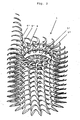
- Fig. 3 shows a variant of the invention in which disks 4, 4 ', 4 "of different thicknesses are used.
- the disks 4' and 4" are thicker than the disk 4 and the disks above and below. This allows greater flexibility in the design and manufacture of the Pelton impeller 1. In addition, this can be the number of individual discs are reduced.
- the individual disks in particular the continuous disks such as the disk 4, can also be further subdivided into individual angle segments, which may facilitate the manufacture and transportation and also may serve to reduce the waste in the production of individual slices.
- the final contour of the Pelton wheel 1 is then produced by milling or grinding Connection of the sheets by brazing the entire bearing surface between the individual discs 4, 4 ', 4 "done.
- a surface application of the solder can be provided or grooves can be provided for embedding solder in strip form on the contact surfaces of the disks.
- an abrasion-resistant coating can be applied to the surface of the cups 2 in a manner known per se.
- the mounting ring 3 has holes 5, which serve to screw with a shaft flange. At the same time this additional clamping of the laminated core and thus greater stability is achieved.
Landscapes
- Engineering & Computer Science (AREA)
- Mechanical Engineering (AREA)
- Chemical & Material Sciences (AREA)
- Combustion & Propulsion (AREA)
- General Engineering & Computer Science (AREA)
- Turbine Rotor Nozzle Sealing (AREA)
- Structures Of Non-Positive Displacement Pumps (AREA)
- Hydraulic Turbines (AREA)
Description
- Die Erfindung betrifft ein Verfahren zum Herstellen eines Peltonlaufrades, bei dem mehrere Scheiben, welche die Kontur des Turbinenlaufrades aufweisen, aufeinander geschichtet und miteinander verbunden werden. Weiters betrifft die Erfindung ein Peltonlaufrad.
- Laufräder von Peltonturbinen werden traditionell als Gusskörper ausgeführt. Bei einem weiteren bekannten Verfahren werden die Schmiedebecher mit einer Schmiedenabe verschweißt. Die Folge derartiger Herstellungsverfahren sind sehr lange Lieferzeiten für die Rohteile von Laufrädern von Turbinen, insbesondere Peltonturbinen, wegen der Notwendigkeit der Beschaffung großer Schmiede- bzw. Gussteile. Bei neueren Verfahren werden gemäß
EP 0 496 181 A1 die Becher von Laufrädern von Peltonturbinen mittels eines Schweißroboters. Lage für Lage aus Schweißgut auf einer Schmiedenabe aufgebaut. Weiters zeigt u.a. dieUS 2008/191487 A1 einen Windrad-Generator mit Savonius-Rotor. Hier wird eine Anzahl von Flügelsegmenten, die alle gleiche Höhe und Durchmesser aufweisen, sowie mittels Stegen an Hülsen, die mit einer Generatorwelle verbunden sind, befestigt. Durch die Ausführung der Hülse und der Generatorwelle mit Zähnen, wird auch die Position der Segmente bestimmt, wobei dadurch auch gewährleistet wird, dass die Segmente direkt übereinander angeordnet sind. DieEP 1 437 512 A2 betrifft eine Zweiwellenvakuumpumpe. Hier wird der Rotor aus einer Vielzahl von Scheiben zusammengesetzt, so dass Anpassungen des Rotorprofiles problemlos vorgenommen werden können. Die Scheiben sind an einer Welle im Winkel zueinander angeordnet und durch Stifte in Position gehalten. Hier wird erst durch das Zusammensetzen von mehreren Scheiben eine Kontur gebildet wobei es darauf ankommt, die sich bildende Kontur immer wieder verändern zu können. - Ziel der Erfindung ist es, ein Peltonlaufrad sowie ein Herstellungsverfahren für Peltonlaufräder zu schaffen, bei dem die Lieferzeiten des Grundmaterials gering sind und die einfach und günstig durchführbar bzw. herstellbar sind.
- Gelöst wird diese Aufgabe bei einem Verfahren der eingangs genannten Art dadurch, dass mehrere Scheiben, welche die Kontur des Peltonlaufrades aufweisen, aufeinander geschichtet und miteinander verschweißt oder durch Hartlöten der Auflagefläche zwischen den einzelnen Scheiben verbunden werden.
- Gelöst wird diese Aufgabe des Weiteren bei einem Peltonlaufrad der eingangs genannten Art dadurch, dass es aus mehreren stoffschlüssig miteinander verbundenen Scheiben aufgebaut ist, die miteinander verschweißt oder durch Hartlöten der Auflagefläche zwischen den einzelnen Scheiben verbunden sind.
- Das erfindungsgemäße Verfahren und das erfindungsgemäße Peltonlaufrad weisen den Vorteil auf, dass sie einfache Teile, nämlich die Kontur des Peltonlaufrades aufweisende Scheiben zur Herstellung verwenden bzw. aus diesen bestehen, welche stoffschlüssig miteinander verbunden sind, sodass die Lieferzeit des Grundmaterials von etwa einem Jahr bei Schmiedeteilen auf wenige Wochen bei Blechen reduziert werden kann. Außerdem sind die einzelnen Scheiben aus Blechen einfach, schnell und günstig herstellbar.
- Eine günstige Weiterbildung der Erfindung ist dadurch gekennzeichnet, dass die Scheiben mittels Laserschnitt oder Brennschnitt aus Blechentafeln bzw. -platten erzeugt werden. Damit lassen sich die einzelnen Scheiben besonders einfach der herzustellenden Geometrie entsprechend fertigen.
- Werden Blechentafeln bzw. -platten unterschiedlicher Dicken herangezogen, so kann der Fertigungsaufwand variabel gestaltet werden, wodurch eine Reduktion der Blechlagen erzielt wird. Es kann dadurch auch in Hinsicht auf den Verschnitt optimiert werden.
- Eine vorteilhafte Weiterbildung der Erfindung ist dadurch gekennzeichnet, dass die Scheiben miteinander verschweißt werden und insbesondere, dass die einzelnen Scheiben durch flächiges Verschweißen der Scheiben wenigstens an Teilen ihrer Oberflächenkontur verbunden werden. Wenn mit dem Schweißgut eine Schicht mit geeigneter Härte und Festigkeit gegen Abrasion hergestellt wird, kann eine Verbindung der Scheiben gemeinsam mit einer hohen Härte der Oberfläche erreicht werden.
- Alternativ können die einzelnen Scheiben durch Hartlöten der Auflagefläche zwischen den einzelnen Blechlagen verbunden werden. Dies gewährleistet eine starke Haftung der einzelnen Schichten aneinander. Bevorzugte werden die einzelnen Scheiben durch Hartlöten der Auflagefläche zwischen den einzelnen Scheiben verbunden, wobei zusätzlich oder alternativ die einzelnen Scheiben Nuten zur Aufnahme von Lot in Bandform aufweisen können.
- Eine günstige Ausgestaltung der Erfindung ist dadurch gekennzeichnet, dass auf die Flügel- bzw. Becheroberfläche eine abrasionsfeste Schicht aufgebracht wird, wobei die abrasionsfeste Schicht durch Flammspritzen oder Plasmaspritzen aufgebracht werden kann.
- Eine vorteilhafte Weiterbildung der Erfindung ist dadurch gekennzeichnet, dass die einzelnen Scheiben in Winkelsegmente unterteilt werden. Dadurch kann der Verschnitt wesentlich reduziert werden. Wenn das Peltonlaufrad aus Scheiben unterschiedlicher Dicken hergestellt wird, ermöglicht dies eine höhere Flexibilität bei der Gestaltung und Fertigung des Peltonlaufrades. Außerdem kann dadurch die Anzahl der einzelnen Scheiben verringert werden.
- Weitere bevorzugte Ausführungsformen der Erfindung sind Gegenstand der übrigen Unteransprüche.
- Weitere Merkmale und Vorteile der Erfindung ergeben sich aus der nachfolgenden Beschreibung eines bevorzugten Ausführungsbeispiels der Erfindung mit Bezug auf die angeschlossenen Zeichnungen, in denen
-
Fig. 1 ein aus Schichten aufgebautes Peltonlaufrad, -
Fig. 2 ein erfindungsgemäßes Peltonlaufrad in Explosionsdarstellung und -
Fig. 3 ein Peltonlaufrad mit Schichten aus Blechen variabler Dicke, -
Fig. 1 zeigt ein Peltonlaufrad 1 mit einer Anzahl von (hier dargestellt zwanzig) Peltonbechern 2 und einem Befestigungsring 3 gemäß der Erfindung. Bisherige Peltonlaufräder nach dem Stand der Technik wurden entweder aus einem Stück hergestellt und damit unter viel Materialverlust und Herstellungsaufwand aus einem Gussstück herausgearbeitet oder die einzelnen, gegossenen oder geschmiedeten Peltonbecher 2 wurden am Befestigungsring 3 separat befestigt. - Beim Peltonlaufrad 1 gemäß der Erfindung wird dem gegenüber eine Anzahl von Scheiben 4, 4', 4" usw. aufeinander geschichtet, die entsprechend der Position am Laufrad 1, d.h. abhängig davon in welcher Ebene sie liegen, unterschiedlich geformt sind. Die aus Blechtafeln herausgeschnittenen oder gegebenenfalls herausgestanzten Scheiben 4, 4', 4" usw. werden dann zu einem Laufrad 1 zusammengefügt und verspannt, worauf die einzelnen Scheiben 4, 4', 4" usw. mittels Schweißen oder Hartlöten fest miteinander verbunden werden.
- In
Fig. 1 ist ein einziger Becher 2 vollständig hergestellt dargestellt, wogegen alle anderen Becher 2 noch nicht fertig gestellt sind. An diesem vollständig hergestellten Becher 2 ist zu erkennen, dass es Scheiben 4', 4" gibt, welche für jeden Becher 2 einzeln bzw. lose vorgefertigten werden, da sie keine direkte Verbindung zu benachbarten Bechern 2 haben, wogegen andere Scheiben 4 einstückig für alle Becher 2 sind. InFig. 2 ist eine Explosionszeichnung eines Peltonlaufrades 1 dargestellt, bei der dies besser zu erkennen ist. Hier sind die einzelnen Scheiben 4, 4', 4" erkennbar, die aus den Blechtafeln herausgeschnitten bzw. herausgestanzt wurden, wobei die Scheiben 4', 4" und die weiter nach oben folgenden Scheiben (aus Gründen der übersichtlicheren Darstellung nur für einen einzigen Becher 2 gezeichnet) separate Teile für jeden Becher 2 sind, wogegen die Scheibe 4 und die nach unten folgenden Scheiben für alle Becher 2 einteilig sind. InFig. 2 ist auch zu erkennen, dass weiter in der Mitte liegende Scheiben entsprechende Abschnitte 3', 3" usw. aufweisen, aus denen der Befestigungsring 3 zusammengesetzt wird. - In
Fig. 1 undFig. 2 werden Bleche bzw. Scheiben 4, 4', 4" gleicher Dicke verwendet.Fig. 3 zeigt eine Variante der Erfindung, bei der Scheiben 4, 4', 4" unterschiedlicher Dicke verwendet werden. Im dargestellten Ausführungsbeispiel sind die Scheiben 4' und 4" dicker als die Scheibe 4 und die darüber und darunter liegenden Scheiben. Dies ermöglicht eine höhere Flexibilität bei der Gestaltung und Fertigung des Peltonlaufrades 1. Außerdem kann dadurch die Anzahl der einzelnen Scheiben verringert werden. - Die einzelnen Scheiben, insbesondere die durchgehenden Scheiben wie die Scheibe 4, können auch noch zusätzlich in einzelne Winkelsegmente unterteilt werden, was unter Umständen die Herstellung und den Transport erleichtert und außerdem dazu dienen kann, den Verschnitt bei der Herstellung der einzelnen Scheiben zu verringern.
- Verbunden werden die einzelnen Scheiben 4, 4', 4" bevorzugt durch Schweißen oder durch Hartlöten. Beim Schweißen kann entweder die gesamte Oberfläche des Peltonlaufrades 1 oder auch nur Flächenabschnitte der Oberfläche, bevorzugt die gesamte Oberfläche der Schaufeln 4, mit einer oder mehreren Schweißlagen überzogen werden, wodurch nicht nur die einzelnen Scheiben miteinander verschweißt werden, sondern gleichzeitig durch eine geeignete Auswahl des Schweißgutes eine Schicht mit geeigneter Härte und Festigkeit gegen Abrasion hergestellt werden kann. Die endgültige Kontur des Peltonlaufrades 1 wird anschließend durch Fräsen oder Schleifen hergestellt. Alternativ kann die Verbindung der Bleche durch Hartlöten der kompletten Auflagefläche zwischen den einzelnen Scheiben 4, 4', 4" erfolgen. Hierzu kann entweder eine flächige Aufbringung des Lots vorgesehen sein oder es können Nuten zur Einbettung von Lot in Bandform an den Kontaktflächen der Scheiben vorgesehen sein. In einem nachfolgenden Arbeitsschritt kann eine abrasionfeste Beschichtung auf an sich bekannte Weise auf die Oberfläche der Becher 2 aufgebracht werden.
- Der Befestigungsring 3 weist Bohrungen 5 auf, die zur Verschraubung mit einem Wellenflansch dienen. Gleichzeitig wird dadurch eine zusätzliche Verspannung des Blechpaketes und somit eine größere Stabilität erreicht.
Claims (13)
- Verfahren zum Herstellen eines Peltonlaufrades (1), bei dem mehrere Scheiben (4, 4', 4"), welche die Kontur des Peltonlaufrades aufweisen, aufeinander geschichtet und miteinander verbunden werden, dadurch gekennzeichnet, dass die Scheiben (4, 4', 4") miteinander verschweißt oder durch Hartlöten der Auflagefläche zwischen den einzelnen Scheiben (4, 4', 4") verbunden werden, wobei die einzelnen
Scheiben (4, 4', 4") durch flächiges Verschweißen der Scheiben (4, 4', 4") wenigstens an Teilen der Oberflächenkontur des Peltonlaufrades (1) verbunden werden. - Verfahren nach Anspruch 1, dadurch gekennzeichnet, dass mit dem Schweißgut eine Schicht mit geeigneter Härte und Festigkeit gegen Abrasion hergestellt wird.
- Verfahren nach einem der Ansprüche 1 bis 2, dadurch gekennzeichnet, dass auf Flügel bzw. Becher (2) des Peltonlaufrades (1) eine abrasionsfeste Schicht aufgebracht wird.
- Verfahren nach Anspruch 3, dadurch gekennzeichnet, dass die abrasionsfeste Schicht durch Flammspritzen oder Plasmaspritzen aufgebracht wird.
- Verfahren nach einem der Ansprüche 1 bis 4, dadurch gekennzeichnet, dass die Scheiben (4, 4', 4") mittels Laserschnitt oder Brennschnitt aus Blechentafeln bzw. -platten erzeugt werden.
- Verfahren nach einem der Ansprüche 1 bis 5, dadurch gekennzeichnet, dass das Turbinenlaufrad aus Scheiben (4, 4', 4") unterschiedlicher Dicke hergestellt wird.
- Verfahren nach einem der Ansprüche 1 bis 6, dadurch gekennzeichnet, dass einzelne Scheiben (4) aus Winkelsegmenten zusammengesetzt werden, bevor das Turbinenlaufrad aus den Scheiben (4, 4', 4") hergestellt wird.
- Peltonlaufrad (1), das aus mehreren stoffschlüssig miteinander verbundenen Scheiben (4, 4', 4") aufgebaut ist, dadurch gekennzeichnet, dass die Scheiben (4, 4', 4") miteinander verschweißt oder durch Hartlöten der Auflagefläche zwischen den einzelnen Scheiben (4, 4', 4") verbunden sind, wobei die einzelnen Scheiben (4, 4', 4") wenigstens an Teilen der Oberfächenkontur des Peltonlaufrades (1) flächig verschweißt sind.
- Peltonlaufrad nach Anspruch 8, dadurch gekennzeichnet, dass wenigstens an Teilen der Obertlächenkontur eine Schicht mit geeigneter Härte und Festigkeit gegen Abrasion aufgeschweißt ist.
- Peltonlaufrad nach einem der Ansprüche 8 bis 9, dadurch gekennzeichnet, dass auf Flügel- bzw. Becher (2) des Peltonlaufrades (1) eine abrasionsfeste Schicht aufgebracht ist.
- Peltonlaufrad nach Anspruch 10, dadurch gekennzeichnet, dass die abrasiortsfeste Schicht durch Flammspritzen oder Plasmaspritzen hergestellt wurde.
- Peltonlaufrad nach einem der Ansprüche 8 bis 11, dadurch gekennzeichnet, dass es aus Scheiben (4, 4', 4") unterschiedlicher Dicke hergestellt ist.
- Peltonlaufrad nach einem der Ansprüche 8 bis 92, dadurch gekennzeichnet, dass einzelne Scheiben (4) aus Winkelsegmenten zusammengesetzt sind.
Applications Claiming Priority (1)
| Application Number | Priority Date | Filing Date | Title |
|---|---|---|---|
| AT0112509A AT508149B1 (de) | 2009-07-16 | 2009-07-16 | Turbinenlaufrad sowie verfahren zu dessen herstellung |
Publications (3)
| Publication Number | Publication Date |
|---|---|
| EP2275668A2 EP2275668A2 (de) | 2011-01-19 |
| EP2275668A3 EP2275668A3 (de) | 2013-03-06 |
| EP2275668B1 true EP2275668B1 (de) | 2015-03-18 |
Family
ID=42548559
Family Applications (1)
| Application Number | Title | Priority Date | Filing Date |
|---|---|---|---|
| EP10006574.7A Not-in-force EP2275668B1 (de) | 2009-07-16 | 2010-06-24 | Turbinenlaufrad sowie Verfahren zu dessen Herstellung |
Country Status (2)
| Country | Link |
|---|---|
| EP (1) | EP2275668B1 (de) |
| AT (1) | AT508149B1 (de) |
Families Citing this family (4)
| Publication number | Priority date | Publication date | Assignee | Title |
|---|---|---|---|---|
| CN110394599B (zh) * | 2019-07-03 | 2024-05-28 | 苏州锦美川自动化科技有限公司 | 水泵涡轮焊接流水线一体成型设备 |
| CN115431237A (zh) * | 2022-09-02 | 2022-12-06 | 重庆通用工业(集团)有限责任公司 | 一种钛合金通风机叶轮划线分度装置及组合方法 |
| FR3166407A1 (fr) * | 2024-09-19 | 2026-03-20 | Matalp | Roue de type Pelton, à augets avec talons assemblés mécaniquement à un moyeu, Procédé de réalisation associé. |
| CN120990783B (zh) * | 2025-10-10 | 2026-04-28 | 长江勘测规划设计研究有限责任公司 | 冲击式水轮机及水斗 |
Family Cites Families (5)
| Publication number | Priority date | Publication date | Assignee | Title |
|---|---|---|---|---|
| GB564309A (en) * | 1943-06-24 | 1944-09-21 | Equi Flow Inc | Laminated gear pumps |
| ES2120414T3 (es) * | 1991-01-21 | 1998-11-01 | Sulzer Hydro Ag | Metodo de fabricacion de piezas metalicas por un aparato de soldadura, y aparato para su realizacion. |
| DE10250482A1 (de) * | 2002-04-09 | 2003-10-30 | Bluenergy Ag Vaduz | Segment-Windschraube |
| DE10300203A1 (de) * | 2003-01-08 | 2004-07-22 | Pfeiffer Vacuum Gmbh | Zweiwellenvakuumpumpe sowie Verfahren zur Herstellung einer Zweiwellenvakuumpumpe |
| US7948110B2 (en) * | 2007-02-13 | 2011-05-24 | Ken Morgan | Wind-driven electricity generation device with Savonius rotor |
-
2009
- 2009-07-16 AT AT0112509A patent/AT508149B1/de not_active IP Right Cessation
-
2010
- 2010-06-24 EP EP10006574.7A patent/EP2275668B1/de not_active Not-in-force
Also Published As
| Publication number | Publication date |
|---|---|
| EP2275668A2 (de) | 2011-01-19 |
| AT508149B1 (de) | 2010-11-15 |
| AT508149A4 (de) | 2010-11-15 |
| EP2275668A3 (de) | 2013-03-06 |
Similar Documents
| Publication | Publication Date | Title |
|---|---|---|
| DE10337866B4 (de) | Verfahren zur Herstellung von Bauteilen für Gasturbinen | |
| EP3251787B1 (de) | Verfahren zur herstellung eines bauteils einer rotationsmaschine sowie bauteil hergestellt nach einem solchen verfahren | |
| EP3085964B1 (de) | Herstellung eines vakuumpumpen-teils mittels eines metallischen, generativen fertigungsverfahrens | |
| DE102012011952B4 (de) | Turbinenschaufelblatt aus Verbundwerkstoff | |
| EP2064440A1 (de) | Verfahren zur herstellung des laufrades einer wasserturbine sowie laufrad | |
| AT516473A2 (de) | Verfahren zum Herstellen eines Schaufelrades aus Sektorsegmenten | |
| EP3273001B1 (de) | Verfahren zum herstellen eines tandem-leitschaufelsegments | |
| DE102010041808A1 (de) | Schaufelkranzsegment, Strömungsmaschine sowie Verfahren zu deren Herstellung | |
| EP2851146A1 (de) | Verfahren zur Herstellung einer Turbinenschaufel und zugehörige Turbinenschaufel | |
| AT508149B1 (de) | Turbinenlaufrad sowie verfahren zu dessen herstellung | |
| EP2228541B1 (de) | Laufrad für eine Kreiselpumpe | |
| DE102008057160A1 (de) | Verfahren zum Austausch eines inneren Scheibenelements einer integral beschaufelten Scheibe | |
| DE102013220983A1 (de) | Laufschaufel für eine Turbomaschine | |
| EP2918776A1 (de) | Verfahren zur herstellung eines doppelreihigen schaufelrads für eine strömungsmaschine und doppelreihiges schaufelrad | |
| EP3281728A1 (de) | Verfahren zur herstellung eines bauteils einer rotationsmaschine sowie bauteil hergestellt nach einem solchen verfahren | |
| DE102012215413A1 (de) | Baugruppe einer Axialturbomaschine | |
| EP1984611A1 (de) | Schaufellagerringanordnung eines turboladers mit variabler turbinengeometrie | |
| DE102009052783A1 (de) | Verfahren zum Herstellen einer Blisk oder eines Blings für eine Strömungsmaschine | |
| DE102006033298A1 (de) | Verfahren zur Herstellung oder Reparatur von als BLISK ausgeführten Verdichtern für ein Gasturbinentriebwerk | |
| EP2860352A1 (de) | Rotor, zugehöriges Herstellungsverfahren und Laufschaufel | |
| WO2010099784A1 (de) | Integral beschaufelter rotor und verfahren zur herstellung eines integral beschaufelten rotors | |
| EP2203646B1 (de) | Radialverdichterlaufrad | |
| DE102008058084A1 (de) | Schaufelrad, insbesondere Leitrad für einen hydrodynamischen Drehzahl-/Drehmomentwandler und Verfahren zur Herstellung eines Schaufelrades | |
| DE102017128093A1 (de) | Laufrad zur Verwendung in einer Strömungsmaschine | |
| DE102005034435B3 (de) | Rotor |
Legal Events
| Date | Code | Title | Description |
|---|---|---|---|
| PUAI | Public reference made under article 153(3) epc to a published international application that has entered the european phase |
Free format text: ORIGINAL CODE: 0009012 |
|
| AK | Designated contracting states |
Kind code of ref document: A2 Designated state(s): AL AT BE BG CH CY CZ DE DK EE ES FI FR GB GR HR HU IE IS IT LI LT LU LV MC MK MT NL NO PL PT RO SE SI SK SM TR |
|
| AX | Request for extension of the european patent |
Extension state: BA ME RS |
|
| PUAL | Search report despatched |
Free format text: ORIGINAL CODE: 0009013 |
|
| AK | Designated contracting states |
Kind code of ref document: A3 Designated state(s): AL AT BE BG CH CY CZ DE DK EE ES FI FR GB GR HR HU IE IS IT LI LT LU LV MC MK MT NL NO PL PT RO SE SI SK SM TR |
|
| AX | Request for extension of the european patent |
Extension state: BA ME RS |
|
| RIC1 | Information provided on ipc code assigned before grant |
Ipc: F03B 1/02 20060101AFI20130130BHEP |
|
| 17P | Request for examination filed |
Effective date: 20130902 |
|
| RBV | Designated contracting states (corrected) |
Designated state(s): AL AT BE BG CH CY CZ DE DK EE ES FI FR GB GR HR HU IE IS IT LI LT LU LV MC MK MT NL NO PL PT RO SE SI SK SM TR |
|
| GRAP | Despatch of communication of intention to grant a patent |
Free format text: ORIGINAL CODE: EPIDOSNIGR1 |
|
| INTG | Intention to grant announced |
Effective date: 20140804 |
|
| GRAP | Despatch of communication of intention to grant a patent |
Free format text: ORIGINAL CODE: EPIDOSNIGR1 |
|
| INTG | Intention to grant announced |
Effective date: 20141215 |
|
| GRAS | Grant fee paid |
Free format text: ORIGINAL CODE: EPIDOSNIGR3 |
|
| GRAA | (expected) grant |
Free format text: ORIGINAL CODE: 0009210 |
|
| AK | Designated contracting states |
Kind code of ref document: B1 Designated state(s): AL AT BE BG CH CY CZ DE DK EE ES FI FR GB GR HR HU IE IS IT LI LT LU LV MC MK MT NL NO PL PT RO SE SI SK SM TR |
|
| REG | Reference to a national code |
Ref country code: GB Ref legal event code: FG4D Free format text: NOT ENGLISH |
|
| REG | Reference to a national code |
Ref country code: CH Ref legal event code: EP |
|
| REG | Reference to a national code |
Ref country code: IE Ref legal event code: FG4D Free format text: LANGUAGE OF EP DOCUMENT: GERMAN |
|
| REG | Reference to a national code |
Ref country code: AT Ref legal event code: REF Ref document number: 716758 Country of ref document: AT Kind code of ref document: T Effective date: 20150415 |
|
| REG | Reference to a national code |
Ref country code: DE Ref legal event code: R096 Ref document number: 502010009129 Country of ref document: DE Effective date: 20150430 |
|
| REG | Reference to a national code |
Ref country code: NL Ref legal event code: VDEP Effective date: 20150318 |
|
| REG | Reference to a national code |
Ref country code: NL Ref legal event code: VDEP Effective date: 20150318 |
|
| PG25 | Lapsed in a contracting state [announced via postgrant information from national office to epo] |
Ref country code: NO Free format text: LAPSE BECAUSE OF FAILURE TO SUBMIT A TRANSLATION OF THE DESCRIPTION OR TO PAY THE FEE WITHIN THE PRESCRIBED TIME-LIMIT Effective date: 20150618 Ref country code: SE Free format text: LAPSE BECAUSE OF FAILURE TO SUBMIT A TRANSLATION OF THE DESCRIPTION OR TO PAY THE FEE WITHIN THE PRESCRIBED TIME-LIMIT Effective date: 20150318 Ref country code: HR Free format text: LAPSE BECAUSE OF FAILURE TO SUBMIT A TRANSLATION OF THE DESCRIPTION OR TO PAY THE FEE WITHIN THE PRESCRIBED TIME-LIMIT Effective date: 20150318 Ref country code: LT Free format text: LAPSE BECAUSE OF FAILURE TO SUBMIT A TRANSLATION OF THE DESCRIPTION OR TO PAY THE FEE WITHIN THE PRESCRIBED TIME-LIMIT Effective date: 20150318 Ref country code: FI Free format text: LAPSE BECAUSE OF FAILURE TO SUBMIT A TRANSLATION OF THE DESCRIPTION OR TO PAY THE FEE WITHIN THE PRESCRIBED TIME-LIMIT Effective date: 20150318 |
|
| REG | Reference to a national code |
Ref country code: LT Ref legal event code: MG4D |
|
| PG25 | Lapsed in a contracting state [announced via postgrant information from national office to epo] |
Ref country code: LV Free format text: LAPSE BECAUSE OF FAILURE TO SUBMIT A TRANSLATION OF THE DESCRIPTION OR TO PAY THE FEE WITHIN THE PRESCRIBED TIME-LIMIT Effective date: 20150318 Ref country code: GR Free format text: LAPSE BECAUSE OF FAILURE TO SUBMIT A TRANSLATION OF THE DESCRIPTION OR TO PAY THE FEE WITHIN THE PRESCRIBED TIME-LIMIT Effective date: 20150619 |
|
| PG25 | Lapsed in a contracting state [announced via postgrant information from national office to epo] |
Ref country code: NL Free format text: LAPSE BECAUSE OF FAILURE TO SUBMIT A TRANSLATION OF THE DESCRIPTION OR TO PAY THE FEE WITHIN THE PRESCRIBED TIME-LIMIT Effective date: 20150318 |
|
| PG25 | Lapsed in a contracting state [announced via postgrant information from national office to epo] |
Ref country code: PT Free format text: LAPSE BECAUSE OF FAILURE TO SUBMIT A TRANSLATION OF THE DESCRIPTION OR TO PAY THE FEE WITHIN THE PRESCRIBED TIME-LIMIT Effective date: 20150720 Ref country code: SK Free format text: LAPSE BECAUSE OF FAILURE TO SUBMIT A TRANSLATION OF THE DESCRIPTION OR TO PAY THE FEE WITHIN THE PRESCRIBED TIME-LIMIT Effective date: 20150318 Ref country code: ES Free format text: LAPSE BECAUSE OF FAILURE TO SUBMIT A TRANSLATION OF THE DESCRIPTION OR TO PAY THE FEE WITHIN THE PRESCRIBED TIME-LIMIT Effective date: 20150318 Ref country code: RO Free format text: LAPSE BECAUSE OF FAILURE TO SUBMIT A TRANSLATION OF THE DESCRIPTION OR TO PAY THE FEE WITHIN THE PRESCRIBED TIME-LIMIT Effective date: 20150318 Ref country code: EE Free format text: LAPSE BECAUSE OF FAILURE TO SUBMIT A TRANSLATION OF THE DESCRIPTION OR TO PAY THE FEE WITHIN THE PRESCRIBED TIME-LIMIT Effective date: 20150318 Ref country code: CZ Free format text: LAPSE BECAUSE OF FAILURE TO SUBMIT A TRANSLATION OF THE DESCRIPTION OR TO PAY THE FEE WITHIN THE PRESCRIBED TIME-LIMIT Effective date: 20150318 |
|
| PG25 | Lapsed in a contracting state [announced via postgrant information from national office to epo] |
Ref country code: IS Free format text: LAPSE BECAUSE OF FAILURE TO SUBMIT A TRANSLATION OF THE DESCRIPTION OR TO PAY THE FEE WITHIN THE PRESCRIBED TIME-LIMIT Effective date: 20150718 Ref country code: PL Free format text: LAPSE BECAUSE OF FAILURE TO SUBMIT A TRANSLATION OF THE DESCRIPTION OR TO PAY THE FEE WITHIN THE PRESCRIBED TIME-LIMIT Effective date: 20150318 |
|
| REG | Reference to a national code |
Ref country code: DE Ref legal event code: R097 Ref document number: 502010009129 Country of ref document: DE |
|
| PG25 | Lapsed in a contracting state [announced via postgrant information from national office to epo] |
Ref country code: IT Free format text: LAPSE BECAUSE OF FAILURE TO SUBMIT A TRANSLATION OF THE DESCRIPTION OR TO PAY THE FEE WITHIN THE PRESCRIBED TIME-LIMIT Effective date: 20150318 |
|
| REG | Reference to a national code |
Ref country code: DE Ref legal event code: R119 Ref document number: 502010009129 Country of ref document: DE |
|
| PLBE | No opposition filed within time limit |
Free format text: ORIGINAL CODE: 0009261 |
|
| STAA | Information on the status of an ep patent application or granted ep patent |
Free format text: STATUS: NO OPPOSITION FILED WITHIN TIME LIMIT |
|
| PG25 | Lapsed in a contracting state [announced via postgrant information from national office to epo] |
Ref country code: MC Free format text: LAPSE BECAUSE OF FAILURE TO SUBMIT A TRANSLATION OF THE DESCRIPTION OR TO PAY THE FEE WITHIN THE PRESCRIBED TIME-LIMIT Effective date: 20150318 Ref country code: DK Free format text: LAPSE BECAUSE OF FAILURE TO SUBMIT A TRANSLATION OF THE DESCRIPTION OR TO PAY THE FEE WITHIN THE PRESCRIBED TIME-LIMIT Effective date: 20150318 |
|
| REG | Reference to a national code |
Ref country code: CH Ref legal event code: PL |
|
| 26N | No opposition filed |
Effective date: 20151221 |
|
| GBPC | Gb: european patent ceased through non-payment of renewal fee |
Effective date: 20150624 |
|
| PG25 | Lapsed in a contracting state [announced via postgrant information from national office to epo] |
Ref country code: SI Free format text: LAPSE BECAUSE OF FAILURE TO SUBMIT A TRANSLATION OF THE DESCRIPTION OR TO PAY THE FEE WITHIN THE PRESCRIBED TIME-LIMIT Effective date: 20150318 Ref country code: LU Free format text: LAPSE BECAUSE OF FAILURE TO SUBMIT A TRANSLATION OF THE DESCRIPTION OR TO PAY THE FEE WITHIN THE PRESCRIBED TIME-LIMIT Effective date: 20150624 |
|
| REG | Reference to a national code |
Ref country code: IE Ref legal event code: MM4A |
|
| REG | Reference to a national code |
Ref country code: FR Ref legal event code: ST Effective date: 20160229 |
|
| PG25 | Lapsed in a contracting state [announced via postgrant information from national office to epo] |
Ref country code: CH Free format text: LAPSE BECAUSE OF NON-PAYMENT OF DUE FEES Effective date: 20150630 Ref country code: LI Free format text: LAPSE BECAUSE OF NON-PAYMENT OF DUE FEES Effective date: 20150630 Ref country code: IE Free format text: LAPSE BECAUSE OF NON-PAYMENT OF DUE FEES Effective date: 20150624 Ref country code: DE Free format text: LAPSE BECAUSE OF NON-PAYMENT OF DUE FEES Effective date: 20160101 Ref country code: GB Free format text: LAPSE BECAUSE OF NON-PAYMENT OF DUE FEES Effective date: 20150624 |
|
| PG25 | Lapsed in a contracting state [announced via postgrant information from national office to epo] |
Ref country code: FR Free format text: LAPSE BECAUSE OF NON-PAYMENT OF DUE FEES Effective date: 20150630 |
|
| REG | Reference to a national code |
Ref country code: AT Ref legal event code: MM01 Ref document number: 716758 Country of ref document: AT Kind code of ref document: T Effective date: 20150624 |
|
| PG25 | Lapsed in a contracting state [announced via postgrant information from national office to epo] |
Ref country code: AT Free format text: LAPSE BECAUSE OF NON-PAYMENT OF DUE FEES Effective date: 20150624 |
|
| PG25 | Lapsed in a contracting state [announced via postgrant information from national office to epo] |
Ref country code: MT Free format text: LAPSE BECAUSE OF FAILURE TO SUBMIT A TRANSLATION OF THE DESCRIPTION OR TO PAY THE FEE WITHIN THE PRESCRIBED TIME-LIMIT Effective date: 20150318 |
|
| PG25 | Lapsed in a contracting state [announced via postgrant information from national office to epo] |
Ref country code: BG Free format text: LAPSE BECAUSE OF FAILURE TO SUBMIT A TRANSLATION OF THE DESCRIPTION OR TO PAY THE FEE WITHIN THE PRESCRIBED TIME-LIMIT Effective date: 20150318 Ref country code: SM Free format text: LAPSE BECAUSE OF FAILURE TO SUBMIT A TRANSLATION OF THE DESCRIPTION OR TO PAY THE FEE WITHIN THE PRESCRIBED TIME-LIMIT Effective date: 20150318 Ref country code: HU Free format text: LAPSE BECAUSE OF FAILURE TO SUBMIT A TRANSLATION OF THE DESCRIPTION OR TO PAY THE FEE WITHIN THE PRESCRIBED TIME-LIMIT; INVALID AB INITIO Effective date: 20100624 |
|
| PG25 | Lapsed in a contracting state [announced via postgrant information from national office to epo] |
Ref country code: CY Free format text: LAPSE BECAUSE OF FAILURE TO SUBMIT A TRANSLATION OF THE DESCRIPTION OR TO PAY THE FEE WITHIN THE PRESCRIBED TIME-LIMIT Effective date: 20150318 |
|
| PG25 | Lapsed in a contracting state [announced via postgrant information from national office to epo] |
Ref country code: BE Free format text: LAPSE BECAUSE OF NON-PAYMENT OF DUE FEES Effective date: 20150630 |
|
| PG25 | Lapsed in a contracting state [announced via postgrant information from national office to epo] |
Ref country code: TR Free format text: LAPSE BECAUSE OF FAILURE TO SUBMIT A TRANSLATION OF THE DESCRIPTION OR TO PAY THE FEE WITHIN THE PRESCRIBED TIME-LIMIT Effective date: 20150318 |
|
| PG25 | Lapsed in a contracting state [announced via postgrant information from national office to epo] |
Ref country code: MK Free format text: LAPSE BECAUSE OF FAILURE TO SUBMIT A TRANSLATION OF THE DESCRIPTION OR TO PAY THE FEE WITHIN THE PRESCRIBED TIME-LIMIT Effective date: 20150318 |
|
| PG25 | Lapsed in a contracting state [announced via postgrant information from national office to epo] |
Ref country code: AL Free format text: LAPSE BECAUSE OF FAILURE TO SUBMIT A TRANSLATION OF THE DESCRIPTION OR TO PAY THE FEE WITHIN THE PRESCRIBED TIME-LIMIT Effective date: 20150318 |