EP2275512A2 - Green-emitting LED - Google Patents
Green-emitting LED Download PDFInfo
- Publication number
- EP2275512A2 EP2275512A2 EP10190226A EP10190226A EP2275512A2 EP 2275512 A2 EP2275512 A2 EP 2275512A2 EP 10190226 A EP10190226 A EP 10190226A EP 10190226 A EP10190226 A EP 10190226A EP 2275512 A2 EP2275512 A2 EP 2275512A2
- Authority
- EP
- European Patent Office
- Prior art keywords
- led
- led according
- phosphor
- mol
- emission
- Prior art date
- Legal status (The legal status is an assumption and is not a legal conclusion. Google has not performed a legal analysis and makes no representation as to the accuracy of the status listed.)
- Granted
Links
- 230000004048 modification Effects 0.000 claims abstract description 21
- 238000012986 modification Methods 0.000 claims abstract description 21
- 229910052693 Europium Inorganic materials 0.000 claims abstract description 10
- OGPBJKLSAFTDLK-UHFFFAOYSA-N europium atom Chemical compound [Eu] OGPBJKLSAFTDLK-UHFFFAOYSA-N 0.000 claims abstract description 4
- 150000001768 cations Chemical class 0.000 claims abstract 3
- OAICVXFJPJFONN-UHFFFAOYSA-N Phosphorus Chemical compound [P] OAICVXFJPJFONN-UHFFFAOYSA-N 0.000 claims description 39
- 230000005855 radiation Effects 0.000 claims description 8
- 238000006243 chemical reaction Methods 0.000 claims description 7
- 238000004020 luminiscence type Methods 0.000 claims description 7
- 238000010586 diagram Methods 0.000 claims description 2
- 239000004615 ingredient Substances 0.000 claims 1
- 239000000463 material Substances 0.000 abstract description 3
- 239000012071 phase Substances 0.000 description 23
- 239000011575 calcium Substances 0.000 description 8
- 238000001228 spectrum Methods 0.000 description 7
- 229910004298 SiO 2 Inorganic materials 0.000 description 6
- 229910052791 calcium Inorganic materials 0.000 description 6
- 239000000203 mixture Substances 0.000 description 6
- 230000005284 excitation Effects 0.000 description 4
- 238000000034 method Methods 0.000 description 4
- 206010001497 Agitation Diseases 0.000 description 3
- 230000007547 defect Effects 0.000 description 3
- 239000002243 precursor Substances 0.000 description 3
- 239000004065 semiconductor Substances 0.000 description 3
- 230000003595 spectral effect Effects 0.000 description 3
- IJGRMHOSHXDMSA-UHFFFAOYSA-N Atomic nitrogen Chemical compound N#N IJGRMHOSHXDMSA-UHFFFAOYSA-N 0.000 description 2
- 230000008901 benefit Effects 0.000 description 2
- 230000015572 biosynthetic process Effects 0.000 description 2
- 230000015556 catabolic process Effects 0.000 description 2
- 230000003081 coactivator Effects 0.000 description 2
- 150000001875 compounds Chemical class 0.000 description 2
- 238000011109 contamination Methods 0.000 description 2
- 238000006731 degradation reaction Methods 0.000 description 2
- 238000009826 distribution Methods 0.000 description 2
- 150000002500 ions Chemical class 0.000 description 2
- 238000004519 manufacturing process Methods 0.000 description 2
- 239000000049 pigment Substances 0.000 description 2
- 230000008569 process Effects 0.000 description 2
- 230000009257 reactivity Effects 0.000 description 2
- 230000006641 stabilisation Effects 0.000 description 2
- 238000011105 stabilization Methods 0.000 description 2
- 239000007858 starting material Substances 0.000 description 2
- 238000003786 synthesis reaction Methods 0.000 description 2
- VXEGSRKPIUDPQT-UHFFFAOYSA-N 4-[4-(4-methoxyphenyl)piperazin-1-yl]aniline Chemical compound C1=CC(OC)=CC=C1N1CCN(C=2C=CC(N)=CC=2)CC1 VXEGSRKPIUDPQT-UHFFFAOYSA-N 0.000 description 1
- OYPRJOBELJOOCE-UHFFFAOYSA-N Calcium Chemical compound [Ca] OYPRJOBELJOOCE-UHFFFAOYSA-N 0.000 description 1
- BVKZGUZCCUSVTD-UHFFFAOYSA-L Carbonate Chemical compound [O-]C([O-])=O BVKZGUZCCUSVTD-UHFFFAOYSA-L 0.000 description 1
- 229910017488 Cu K Inorganic materials 0.000 description 1
- 229910017541 Cu-K Inorganic materials 0.000 description 1
- 239000004593 Epoxy Substances 0.000 description 1
- KRHYYFGTRYWZRS-UHFFFAOYSA-M Fluoride anion Chemical compound [F-] KRHYYFGTRYWZRS-UHFFFAOYSA-M 0.000 description 1
- 229910004283 SiO 4 Inorganic materials 0.000 description 1
- 229910004122 SrSi Inorganic materials 0.000 description 1
- 238000002441 X-ray diffraction Methods 0.000 description 1
- HCHKCACWOHOZIP-UHFFFAOYSA-N Zinc Chemical compound [Zn] HCHKCACWOHOZIP-UHFFFAOYSA-N 0.000 description 1
- 238000010521 absorption reaction Methods 0.000 description 1
- 239000012190 activator Substances 0.000 description 1
- XAGFODPZIPBFFR-UHFFFAOYSA-N aluminium Chemical compound [Al] XAGFODPZIPBFFR-UHFFFAOYSA-N 0.000 description 1
- 229910052782 aluminium Inorganic materials 0.000 description 1
- 238000000137 annealing Methods 0.000 description 1
- QVGXLLKOCUKJST-UHFFFAOYSA-N atomic oxygen Chemical compound [O] QVGXLLKOCUKJST-UHFFFAOYSA-N 0.000 description 1
- 238000005266 casting Methods 0.000 description 1
- 239000000919 ceramic Substances 0.000 description 1
- GTDCAOYDHVNFCP-UHFFFAOYSA-N chloro(trihydroxy)silane Chemical class O[Si](O)(O)Cl GTDCAOYDHVNFCP-UHFFFAOYSA-N 0.000 description 1
- 229910017052 cobalt Inorganic materials 0.000 description 1
- 239000010941 cobalt Substances 0.000 description 1
- GUTLYIVDDKVIGB-UHFFFAOYSA-N cobalt atom Chemical compound [Co] GUTLYIVDDKVIGB-UHFFFAOYSA-N 0.000 description 1
- 229940125898 compound 5 Drugs 0.000 description 1
- 239000000470 constituent Substances 0.000 description 1
- 238000010276 construction Methods 0.000 description 1
- 239000013078 crystal Substances 0.000 description 1
- 230000001419 dependent effect Effects 0.000 description 1
- 238000000295 emission spectrum Methods 0.000 description 1
- 238000005516 engineering process Methods 0.000 description 1
- 230000002349 favourable effect Effects 0.000 description 1
- 230000004907 flux Effects 0.000 description 1
- -1 for example Chemical class 0.000 description 1
- 239000012535 impurity Substances 0.000 description 1
- 239000007791 liquid phase Substances 0.000 description 1
- 230000014759 maintenance of location Effects 0.000 description 1
- 229910052757 nitrogen Inorganic materials 0.000 description 1
- 238000013386 optimize process Methods 0.000 description 1
- 239000001301 oxygen Substances 0.000 description 1
- 229910052760 oxygen Inorganic materials 0.000 description 1
- 238000004382 potting Methods 0.000 description 1
- 238000004886 process control Methods 0.000 description 1
- 229910052761 rare earth metal Inorganic materials 0.000 description 1
- 150000002910 rare earth metals Chemical class 0.000 description 1
- 239000011347 resin Substances 0.000 description 1
- 229920005989 resin Polymers 0.000 description 1
- 150000004760 silicates Chemical class 0.000 description 1
- 229910052710 silicon Inorganic materials 0.000 description 1
- 239000005049 silicon tetrachloride Substances 0.000 description 1
- 238000006467 substitution reaction Methods 0.000 description 1
- 150000003568 thioethers Chemical class 0.000 description 1
- WFKWXMTUELFFGS-UHFFFAOYSA-N tungsten Chemical compound [W] WFKWXMTUELFFGS-UHFFFAOYSA-N 0.000 description 1
- 229910052721 tungsten Inorganic materials 0.000 description 1
- 239000010937 tungsten Substances 0.000 description 1
- 229910052725 zinc Inorganic materials 0.000 description 1
- 239000011701 zinc Substances 0.000 description 1
Images


Classifications
-
- C—CHEMISTRY; METALLURGY
- C09—DYES; PAINTS; POLISHES; NATURAL RESINS; ADHESIVES; COMPOSITIONS NOT OTHERWISE PROVIDED FOR; APPLICATIONS OF MATERIALS NOT OTHERWISE PROVIDED FOR
- C09K—MATERIALS FOR MISCELLANEOUS APPLICATIONS, NOT PROVIDED FOR ELSEWHERE
- C09K11/00—Luminescent, e.g. electroluminescent, chemiluminescent materials
- C09K11/08—Luminescent, e.g. electroluminescent, chemiluminescent materials containing inorganic luminescent materials
- C09K11/59—Luminescent, e.g. electroluminescent, chemiluminescent materials containing inorganic luminescent materials containing silicon
-
- H—ELECTRICITY
- H01—ELECTRIC ELEMENTS
- H01L—SEMICONDUCTOR DEVICES NOT COVERED BY CLASS H10
- H01L33/00—Semiconductor devices with at least one potential-jump barrier or surface barrier specially adapted for light emission; Processes or apparatus specially adapted for the manufacture or treatment thereof or of parts thereof; Details thereof
- H01L33/48—Semiconductor devices with at least one potential-jump barrier or surface barrier specially adapted for light emission; Processes or apparatus specially adapted for the manufacture or treatment thereof or of parts thereof; Details thereof characterised by the semiconductor body packages
- H01L33/50—Wavelength conversion elements
- H01L33/501—Wavelength conversion elements characterised by the materials, e.g. binder
- H01L33/502—Wavelength conversion materials
-
- C—CHEMISTRY; METALLURGY
- C09—DYES; PAINTS; POLISHES; NATURAL RESINS; ADHESIVES; COMPOSITIONS NOT OTHERWISE PROVIDED FOR; APPLICATIONS OF MATERIALS NOT OTHERWISE PROVIDED FOR
- C09K—MATERIALS FOR MISCELLANEOUS APPLICATIONS, NOT PROVIDED FOR ELSEWHERE
- C09K11/00—Luminescent, e.g. electroluminescent, chemiluminescent materials
- C09K11/08—Luminescent, e.g. electroluminescent, chemiluminescent materials containing inorganic luminescent materials
- C09K11/0883—Arsenides; Nitrides; Phosphides
-
- C—CHEMISTRY; METALLURGY
- C09—DYES; PAINTS; POLISHES; NATURAL RESINS; ADHESIVES; COMPOSITIONS NOT OTHERWISE PROVIDED FOR; APPLICATIONS OF MATERIALS NOT OTHERWISE PROVIDED FOR
- C09K—MATERIALS FOR MISCELLANEOUS APPLICATIONS, NOT PROVIDED FOR ELSEWHERE
- C09K11/00—Luminescent, e.g. electroluminescent, chemiluminescent materials
- C09K11/08—Luminescent, e.g. electroluminescent, chemiluminescent materials containing inorganic luminescent materials
- C09K11/55—Luminescent, e.g. electroluminescent, chemiluminescent materials containing inorganic luminescent materials containing beryllium, magnesium, alkali metals or alkaline earth metals
-
- C—CHEMISTRY; METALLURGY
- C09—DYES; PAINTS; POLISHES; NATURAL RESINS; ADHESIVES; COMPOSITIONS NOT OTHERWISE PROVIDED FOR; APPLICATIONS OF MATERIALS NOT OTHERWISE PROVIDED FOR
- C09K—MATERIALS FOR MISCELLANEOUS APPLICATIONS, NOT PROVIDED FOR ELSEWHERE
- C09K11/00—Luminescent, e.g. electroluminescent, chemiluminescent materials
- C09K11/08—Luminescent, e.g. electroluminescent, chemiluminescent materials containing inorganic luminescent materials
- C09K11/77—Luminescent, e.g. electroluminescent, chemiluminescent materials containing inorganic luminescent materials containing rare earth metals
- C09K11/7728—Luminescent, e.g. electroluminescent, chemiluminescent materials containing inorganic luminescent materials containing rare earth metals containing europium
- C09K11/77347—Silicon Nitrides or Silicon Oxynitrides
-
- H—ELECTRICITY
- H01—ELECTRIC ELEMENTS
- H01L—SEMICONDUCTOR DEVICES NOT COVERED BY CLASS H10
- H01L2224/00—Indexing scheme for arrangements for connecting or disconnecting semiconductor or solid-state bodies and methods related thereto as covered by H01L24/00
- H01L2224/01—Means for bonding being attached to, or being formed on, the surface to be connected, e.g. chip-to-package, die-attach, "first-level" interconnects; Manufacturing methods related thereto
- H01L2224/26—Layer connectors, e.g. plate connectors, solder or adhesive layers; Manufacturing methods related thereto
- H01L2224/31—Structure, shape, material or disposition of the layer connectors after the connecting process
- H01L2224/32—Structure, shape, material or disposition of the layer connectors after the connecting process of an individual layer connector
- H01L2224/321—Disposition
- H01L2224/32151—Disposition the layer connector connecting between a semiconductor or solid-state body and an item not being a semiconductor or solid-state body, e.g. chip-to-substrate, chip-to-passive
- H01L2224/32221—Disposition the layer connector connecting between a semiconductor or solid-state body and an item not being a semiconductor or solid-state body, e.g. chip-to-substrate, chip-to-passive the body and the item being stacked
- H01L2224/32245—Disposition the layer connector connecting between a semiconductor or solid-state body and an item not being a semiconductor or solid-state body, e.g. chip-to-substrate, chip-to-passive the body and the item being stacked the item being metallic
-
- H—ELECTRICITY
- H01—ELECTRIC ELEMENTS
- H01L—SEMICONDUCTOR DEVICES NOT COVERED BY CLASS H10
- H01L2224/00—Indexing scheme for arrangements for connecting or disconnecting semiconductor or solid-state bodies and methods related thereto as covered by H01L24/00
- H01L2224/01—Means for bonding being attached to, or being formed on, the surface to be connected, e.g. chip-to-package, die-attach, "first-level" interconnects; Manufacturing methods related thereto
- H01L2224/42—Wire connectors; Manufacturing methods related thereto
- H01L2224/47—Structure, shape, material or disposition of the wire connectors after the connecting process
- H01L2224/48—Structure, shape, material or disposition of the wire connectors after the connecting process of an individual wire connector
- H01L2224/4805—Shape
- H01L2224/4809—Loop shape
- H01L2224/48091—Arched
-
- H—ELECTRICITY
- H01—ELECTRIC ELEMENTS
- H01L—SEMICONDUCTOR DEVICES NOT COVERED BY CLASS H10
- H01L2224/00—Indexing scheme for arrangements for connecting or disconnecting semiconductor or solid-state bodies and methods related thereto as covered by H01L24/00
- H01L2224/01—Means for bonding being attached to, or being formed on, the surface to be connected, e.g. chip-to-package, die-attach, "first-level" interconnects; Manufacturing methods related thereto
- H01L2224/42—Wire connectors; Manufacturing methods related thereto
- H01L2224/47—Structure, shape, material or disposition of the wire connectors after the connecting process
- H01L2224/48—Structure, shape, material or disposition of the wire connectors after the connecting process of an individual wire connector
- H01L2224/481—Disposition
- H01L2224/48151—Connecting between a semiconductor or solid-state body and an item not being a semiconductor or solid-state body, e.g. chip-to-substrate, chip-to-passive
- H01L2224/48221—Connecting between a semiconductor or solid-state body and an item not being a semiconductor or solid-state body, e.g. chip-to-substrate, chip-to-passive the body and the item being stacked
- H01L2224/48245—Connecting between a semiconductor or solid-state body and an item not being a semiconductor or solid-state body, e.g. chip-to-substrate, chip-to-passive the body and the item being stacked the item being metallic
- H01L2224/48247—Connecting between a semiconductor or solid-state body and an item not being a semiconductor or solid-state body, e.g. chip-to-substrate, chip-to-passive the body and the item being stacked the item being metallic connecting the wire to a bond pad of the item
-
- H—ELECTRICITY
- H01—ELECTRIC ELEMENTS
- H01L—SEMICONDUCTOR DEVICES NOT COVERED BY CLASS H10
- H01L2224/00—Indexing scheme for arrangements for connecting or disconnecting semiconductor or solid-state bodies and methods related thereto as covered by H01L24/00
- H01L2224/73—Means for bonding being of different types provided for in two or more of groups H01L2224/10, H01L2224/18, H01L2224/26, H01L2224/34, H01L2224/42, H01L2224/50, H01L2224/63, H01L2224/71
- H01L2224/732—Location after the connecting process
- H01L2224/73251—Location after the connecting process on different surfaces
- H01L2224/73265—Layer and wire connectors
Definitions
- the invention is based on a green emitting LED.
- green emitting is meant in particular an emission in the range of 560 m.
- a color-emitting LED is realized by a correspondingly adapted chip.
- this is problematic because established techniques such as an InGaN chip (blue) or an InGaA1P chip (red) can not be used because of lack of efficiency.
- special solutions must be used. Examples of such special solutions are in EP 584 599 . DE 198 06 536 and DE 100 24 924 to find. However, they still have a relatively low efficiency. In addition, they show a relatively strong temperature drift of the color locus of the emission.
- Oxinitridosilicate phosphors are known per se under the abbreviation MSiON; see for example “ On new rare-earth doped M-Si-Al-ON materials ", J. Van Krevel, Eindhoven University of Technology 2000, ISBN 90-386-2711-4, chapter 6 , they are endowed with Tb. Emission we achieved when excited by 365 nm or 254 nm.
- This HT modification is characterized by the fact that it can be excited broadband excitation, namely in a wide range of 200 to 480 nm that it has an extremely high stability to external influences, ie at 150 ° C shows no measurable degradation, and that they an extremely good color stability under changing conditions shows (between 20 and 100 ° C only slight drift detectable).
- This phosphor is often called Sr-sion: Eu in the following.
- the synthesis range is 1300 to 1600 ° C.
- Another determining factor is the reactivity of the starting components. This should be as high as possible.
- this phosphor can be efficiently excited by an LED, especially of the InGaN type.
- the two phases differ fundamentally in their suitability as a phosphor. While the NT phase as an Eudotierter phosphor is limited to use, and more orange-red emitted, the HT phase shows excellent suitability as a phosphor that emits green. Often there is a mixture of both modifications, which shows broadband both emissions. It is therefore desirable to produce the HT phase as pure as possible, with at least 50% proportion, preferably at least 70%, particularly preferably at least 85% proportion.
- annealing process that is performed at a minimum of 1300 ° C but not more than 1600 ° C.
- Preference is given to a temperature range of about 1450 to 1580 ° C, since at lower temperature increasingly NT phase is formed and at higher temperature, the phosphor is increasingly difficult to process, and is present from about 1600 ° C as a hard sintered ceramic or melt.
- the optimum temperature range depends on the exact composition and properties of the starting materials.
- Sr-Sion phosphor is an approach of the starting materials, which is substantially stoichiometric using the basic components SiO 2 , SrCO 3 and Si 3 N 4 .
- Sr is hereby exemplified by M.
- the deviation should in particular not exceed 10%, preferably 5%, of the ideal stoichiometric approach, whereby also the possible addition of a flux, as is often the case, is included.
- Particularly preferred is a maximum deviation of 1%.
- the europium contribution of the doping which is realized, for example, as oxide Eu 2 O 3 .
- This finding is in contrast to the previous approach, the basic component of SiO 2 clearly substoichiometric admit. This finding is also particularly surprising because other sions recommended as fluorescent, such as Ba-Sion according to the doctrine of EP-PA 02 021 117.8 just in the SiO 2 sub-shot to be produced.
- a corresponding approach for the Sr sion MSi 2 O 2 N 2 therefore uses 11 to 13 wt .-% SiO 2 , 27 to 29 wt .-% Si 3 N 4 , balance SrCO 3 .
- Ba and Ca fractions of M are added as carbonate accordingly.
- Europium is added according to the desired doping, for example as oxide or fluoride, as a replacement for SrCO 3 .
- the approach MSi 2 O 2 N 2 also means any deviations from the exact stoichiometry, as far as they are balanced in terms of charge retention.
- the starting components of the host lattice in particular Si 3 N 4 , have the highest possible purity. Therefore, Si 3 N 4 , which is synthesized from the liquid phase, starting, for example, from silicon tetrachloride, is particularly preferred.
- the contamination with tungsten and cobalt has proven to be critical.
- the impurity should be as low as possible, in particular, it should be less than 100 ppm, in particular less than 50 ppm, based on these precursors.
- the highest possible reactivity is advantageous, it can be quantified by the reactive surface (BET). This should be at least 6 m 2 / g, advantageously at least 8 m 2 / g.
- the contamination of aluminum and calcium, based on this precursor Si 3 N 4 should be as possible below 100 ppm.
- this compound is a notable phosphor per se, it is very disturbing in the context of Sr-sion synthesis, as are other nitridosilicates, because these foreign phases absorb the Sr-sion green radiation and eventually convert it to the known red radiation of the nitridosilicates , Conversely, if too much SiO 2 is added, Sr silicates such as, for example, Sr 2 SiO 4 are formed because an excess of oxygen is formed.
- Both foreign phases absorb the usable green emission or at least lead to lattice defects such as vacancies, which severely impair the efficiency of the phosphor.
- a guideline serves the guideline that the proportion of foreign phases possible less than 15%, preferably even less than 5%.
- This HT modification is characterized by the fact that it can be stimulated with broadband, namely in a wide range from 50 to 480 nm, in particular 150 to 480 nm, particularly preferably from 250 to 470 nm, that it has an extremely high stability against external influences , so at 150 ° C in air shows no measurable degradation, and that it shows an extremely good color stability in changing conditions.
- Other pluses are its low absorption in the red, which is particularly advantageous in phosphor mixtures.
- This phosphor is often called Sr-sion: Eu in the following.
- a predominance of the HT modification is evident inter alia from the fact that the characteristic peak of the NT modification in the XRD spectrum at about 28.2 ° an intensity of less than 1: 1, preferably less than 1: 2, compared to the peak with highest intensity from the triad of reflections of HT modification, which are in the XRD spectrum at 25 to 27 °, has.
- the XRD spectra listed here each refer to an excitation by the known Cu-K ⁇ line.
- the half width of the HT variant is much lower in the case of the optimized HT variant than in the case of the HT variant the simple foreign phase and defect-containing mixture and is in the range 70 to 80 nm, while the simple Fremdphasen- or defect-containing mixture shows a half-width of about 110 to 120 nm.
- the dominant wavelength is generally shorter in the HT modification, typically 10 to 20 nm shorter, than in a sample that contains a lot of foreign phase.
- the efficiency of the high-purity HT modification is typically at least 20% higher, sometimes significantly higher, than in the case of the NT-dominated or highly foreign phase-containing mixture.
- a characteristic feature of a sufficiently low proportion of the NT modification and foreign phases is a half-width (FWHM) of the emission of less than 90 nm.
- FWHM half-width
- the predominant peak in the XRD spectrum of the HT modification is the peak at about 31.7 °.
- other prominent peaks are the three peaks of approximately equal intensity between 25 and 27 ° (25.3 and 26.0 and 26.3 °), with the minimum deflection peak being the most intense.
- another intense peak is 12.6 °.
- This phosphor is mainly green emitting with a dominant wavelength in the 555 to 565 nm range.
- Both phases of Sr-sion: Eu can crystallize analogously to the two structurally different host lattice modifications and can be prepared in each case via the stoichiometry SrSi2O2N2: Eu. Small deviations from this stoichiometry are possible.
- the Eu-doped host lattices surprisingly both luminesce upon excitation in the blue or UV, however, depending on Host lattice modification with different emission color.
- a desired property of the phosphor can be set precisely.
- An advantage of the HT phase is the uniformly good excitability over a very wide spectral range with only little varying quantum efficiency.
- the luminescence of the HT modification in a wide temperature range depends only weakly on the temperature. This is the first time a green emitting phosphor, preferably for LED applications, found that manages without special measures for stabilization. This distinguishes him especially against the hitherto regarded as the most promising candidate phosphors for this task, namely thiogallate phosphors or chlorosilicates.
- the Sion compounds with M (Sr, Ba), preferably without Ba or with Ba content up to 10%, are efficient phosphors with a wide range of emission maxima. These are usually shorter wavelength than pure Sr-Sion, preferably between 520 and 565 nm.
- the achievable color space can also be extended by small amounts (preferably up to 30 mol%) of Ca and / or zinc; As a result, the emission maxima are shifted to the longer wavelength range, compared to pure Sr-Sion, and by partial replacement (up to 25 mol%) of Si by Ge and / or Sn.
- Another embodiment is the partial substitution of M, in particular Sr, by trivalent or monovalent ions such as La 3+ or Li +. A proportion of these ions of not more than 20 mol% of M. is preferred.
- the phosphor converts the light of a blue or UV LED with a quantum efficiency of well over 80%.
- the lumen-weighted efficiency is comparable to the typical white LEDs on YAG: Ce-based.
- a "pure green" conversion LED is almost an order of magnitude more efficient than the pure semiconductor version.
- a further advantage is to be considered that the emission color of the luminescence conversion LED is virtually independent of the operating temperature, so that the LED can be operated well at different outdoor temperatures and is dunstable Farbortstabil.
- the invention further relates to a lighting system with LEDs as described above, wherein the lighting system further includes electronic components. These convey, for example, the dimmability.
- Another task of the electronics is the control of individual LEDs or groups of LEDs. These functions can be realized by previously known electronic elements.
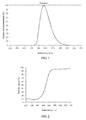
- FIG. 1 A concrete example of the phosphor according to the invention is in FIG. 1 shown.
- This is the emission of the phosphor SrSi 2 N 2 O 2 : (5% Eu 2+ ) in HT modification, in which the Eu content accounts for 5 mol% of the lattice sites occupied by Sr.
- the emission maximum is 540 nm, the mean wavelength ⁇ dom at 558 nm.
- the excitation took place here at 460 nm.
- the FWHM is 76 nm.
- the quantum efficiency is about 90%.
- FIG. 2 shows the diffuse reflection spectrum of this phosphor. It shows a pronounced minimum in the range below 440 nm, which thus demonstrates the good excitability in this area.
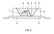
- the construction of a light source for white light is in FIG. 3 shown explicitly.
- the light source is a semiconductor component with a chip 1 of the type InGaN with a peak emission wavelength in the UV of, for example, 405 nm, up to 430 nm, which is embedded in an opaque base housing 8 in the region of a recess 9.
- the chip 1 is connected via a bonding wire 14 to a first terminal 3 and directly to a second electrical terminal 2.
- the recess 9 is filled with a potting compound 5 which contains as main constituents an epoxy casting resin (80 to 90% by weight) and phosphor pigments 6 (less than 20% by weight).
- the recess has a wall 17, which serves as a reflector for the primary and secondary radiation from the chip 1 and the pigments 6.
- the primary radiation of the UV LED is completely converted from the phosphor to green.
- the phosphor used is the oxynitridosilicate described above.
- FIG. 5 shows the spectral distribution of the emission of a luminescence conversion LED based on a UV primary emitting LED with peak at 405 nm.
Abstract
Description
Diese Anmeldung steht in engem Zusammenhang mit folgenden Anmeldungen:
Die Erfindung geht aus von einer grün emittierenden LED. Unter grün emittierend wird hier insbesondere eine Emission im Bereich um 560 m verstanden.The invention is based on a green emitting LED. By green emitting is meant in particular an emission in the range of 560 m.
Üblicherweise wird eine farbig emittierende LED durch einen entsprechend angepassten Chip realisiert. Im Falle einer grünen Emission ist dies jedoch problematisch, da etablierte Techniken wie ein InGaN-Chip (blau) oder ein InGaA1P-Chip (rot) wegen mangelnder Effizienz nicht eingesetzt werden können. Stattdessen müssen Sonderlösungen verwendet werden. Beispiele für derartige Sonderlösungen sind in
Als Alternative sind daher grün emittierende LEDs auf Basis von Lumineszenzkonversions-LEDs entwickelt worden. Beispiele finden sich in
Leuchtstoffe des Typs Oxinitridosilikat sind an sich unter der Kurzformel MSiON bekannt; siehe beispielsweise "
Ein neuartiger Leuchtstoff ist aus der noch unveröffentlichten
Es ist Aufgabe der vorliegenden Erfindung, eine grün emittierende LED gemäß dem Oberbegriff des Anspruchs 1 bereitzustellen, deren Effizienz möglichst hoch ist. Eine weitere Aufgabe ist die Stabilisierung des Farborts.It is an object of the present invention to provide a green emitting LED according to the preamble of
Diese Aufgabe wird durch die kennzeichnenden Merkmale des Anspruchs 1 gelöst. Besonders vorteilhafte Ausgestaltungen finden sich in den abhängigen Ansprüchen.This object is solved by the characterizing features of
Bisher gibt es keinen grün emittierenden Leuchtstoff hoher Effizienz, der gleichzeitig unempfindlich gegen äußere Einflüsse ist und in einer LED nutzbar wäre.So far there is no green emitting phosphor of high efficiency, which is also insensitive to external influences and could be used in an LED.
Erfindungsgemäß wird ein Leuchtstoff vorgeschlagen, der ein Oxinitridosilikat der Formel MSi2O2N2 (M = Ca, Sr, Ba) darstellt, das mit zweiwertigem Eu aktiviert ist, unter evtl. weiterer Zugabe von Mn als Koaktivator, wobei der Leuchtstoff überwiegend oder allein, also mit einem Anteil von mehr als 50 % des Leuchtstoffs, aus der HT-Phase besteht. Diese HT-Modifikation zeichnet sich dadurch aus, dass sie breitbandig anregbar aus, nämlich in einem weiten Bereich von 200 bis 480 nm, dass sie eine extrem hohe Stabilität gegen äußere Einflüsse besitzt, also bei 150°C keine messbare Degradation zeigt, und dass sie eine extrem gute Farbortstabilität unter wechselnden Bedingungen zeigt (zwischen 20 und 100 °C nur geringe Drift nachweisbar). Dieser Leuchtstoff wird im folgenden oft Sr-Sion:Eu genannt.According to the invention, a phosphor is proposed which is an oxinitridosilicate of the formula MSi 2 O 2 N 2 (M = Ca, Sr, Ba), which is activated with divalent Eu, with possibly further addition of Mn as coactivator, the phosphor predominantly or alone, ie with a share of more than 50% of the phosphor, consists of the HT phase. This HT modification is characterized by the fact that it can be excited broadband excitation, namely in a wide range of 200 to 480 nm that it has an extremely high stability to external influences, ie at 150 ° C shows no measurable degradation, and that they an extremely good color stability under changing conditions shows (between 20 and 100 ° C only slight drift detectable). This phosphor is often called Sr-sion: Eu in the following.
Bei der Herstellung des neuartigen Leuchtstoffs kommt es vor allem auf eine hohe Temperatur an, der Synthesebereich liegt bei 1300 bis 1600 °C. Ein anderer bestimmender Faktor ist die Reaktivität der Ausgangskomponenten. Diese sollte möglichst hoch sein.In the production of the novel phosphor, it is mainly on a high temperature, the synthesis range is 1300 to 1600 ° C. Another determining factor is the reactivity of the starting components. This should be as high as possible.
Insbesondere kann dieser Leuchtstoff von einer LED, vor allem vom Typ InGaN, effizient angeregt werden.In particular, this phosphor can be efficiently excited by an LED, especially of the InGaN type.
Der aus
Sr(1-x-y)BayCax mit x+y < 0,5 , im folgenden Sr-Sion genannt, nur schwer beherrschbar. Obwohl einzelne Versuchsbedingungen hervorragende Ergebnisse liefern, fehlt bislang eine Richtschnur, um zuverlässig gewünschte Ergebnisse zu erhalten. Hinzu kommt eine gewisse Neigung, dass sich bei hoher Temperaturbelastung die Effizienz des Leuchtstoffs verringert und der Farbort zu stark variiert.Sr (1-xy) Ba y Ca x with x + y <0.5, called Sr-sion in the following, difficult to control. Although individual test conditions provide excellent results, so far no guideline is needed to reliably obtain desired results. In addition, there is a certain tendency that at high temperature load, the efficiency of the phosphor is reduced and the color point varies too much.
Überraschenderweise hat sich nun gezeigt, dass sich die beiden Phasen in ihrer Eignung als Leuchtstoff grundlegend unterscheiden. Während die NT-Phase als Eudotierter Leuchtstoff nur bedingt zu gebrauchen ist, und eher orange-rot emittiert, zeigt die HT-Phase eine hervorragende Eignung als Leuchtstoff, der grün emittiert. Häufig liegt eine Mischung beider Modifikationen vor, die breitbandig beide Emissionen erkennen lässt. Gewünscht ist daher, die HT-Phase möglichst rein, mit mindestens 50 % Anteil, bevorzugt mindestens 70 %, besonders bevorzugt mindestens 85% Anteil herzustellen.Surprisingly, it has now been shown that the two phases differ fundamentally in their suitability as a phosphor. While the NT phase as an Eudotierter phosphor is limited to use, and more orange-red emitted, the HT phase shows excellent suitability as a phosphor that emits green. Often there is a mixture of both modifications, which shows broadband both emissions. It is therefore desirable to produce the HT phase as pure as possible, with at least 50% proportion, preferably at least 70%, particularly preferably at least 85% proportion.
Dafür ist ein Glühprozess erforderlich, der bei mindestens 1300 °C, aber nicht mehr als 1600 °C durchgeführt wird. Bevorzugt ist ein Temperaturbereich von etwa 1450 bis 1580 °C, da bei geringerer Temperatur zunehmend NT-Phase entsteht und bei höherer Temperatur der Leuchtstoff zunehmend schlechter verarbeitbar ist, und ab etwa 1600 °C als hart gesinterte Keramik oder Schmelze vorliegt. Der optimale Temperaturbereich hängt von der genauen Zusammensetzung und den Eigenschaften der Ausgangsmaterialien ab.This requires an annealing process that is performed at a minimum of 1300 ° C but not more than 1600 ° C. Preference is given to a temperature range of about 1450 to 1580 ° C, since at lower temperature increasingly NT phase is formed and at higher temperature, the phosphor is increasingly difficult to process, and is present from about 1600 ° C as a hard sintered ceramic or melt. The optimum temperature range depends on the exact composition and properties of the starting materials.
Besonders wichtig für das Herstellen eines effizienten Leuchtstoffs des Typs Sr-Sion ist ein Ansatz der Ausgangsprodukte, der im wesentlichen stöchiometrisch ist unter Verwendung der Grundkomponenten SiO 2, SrCO 3 sowie Si 3 N 4. Sr steht hier beispielhaft stellvertretend für M. Die Abweichung sollte insbesondere 10 %, bevorzugt 5 %, des idealen stöchiometrischen Ansatzes nicht überschreiten, wobei auch die etwaige Zugabe eines Schmelzmittels, wie es oft üblich ist, dabei eingeschlossen ist. Besonders bevorzugt ist eine maximale Abweichung von 1 %. Hinzu kommt ein Vorläufer für den Europium-Beitrag der Dotierung, der beispielsweise als Oxid Eu 2 O 3 realisiert wird. Diese Erkenntnis steht im Gegensatz zu der bisherigen Vorgehensweise, die Grundkomponente SiO 2 deutlich unterstöchiometrisch zuzugeben. Besonders überraschend ist diese Erkenntnis auch deswegen, weil andere als Leuchtstoff empfohlene Sione wie Ba-Sion gemäß der Lehre von
Ein entsprechender Ansatz für das Sr-Sion MSi2O2N2 verwendet daher 11 bis 13 Gew.-% SiO 2 , 27 bis 29 Gew.-% Si 3 N 4 , Rest SrCO 3. Ba- und Ca- Anteile an M werden entsprechend als Carbonat zugesetzt. Europium wird entsprechend der gewünschten Dotierung, beispielsweise als Oxid oder Fluorid, als Ersatz für SrCO 3 zugesetzt. Der Ansatz MSi2O2N2 meint dabei auch etwaige Abweichungen von der exakten Stöchiometrie, soweit sie hinsichtlich der Ladungserhaltung ausgeglichen sind.A corresponding approach for the Sr sion MSi 2 O 2 N 2 therefore uses 11 to 13 wt .-% SiO 2 , 27 to 29 wt .-% Si 3 N 4 , balance SrCO 3 . Ba and Ca fractions of M are added as carbonate accordingly. Europium is added according to the desired doping, for example as oxide or fluoride, as a replacement for SrCO 3 . The approach MSi 2 O 2 N 2 also means any deviations from the exact stoichiometry, as far as they are balanced in terms of charge retention.
Als besonders günstig hat sich erwiesen, dass die Ausgangskomponenten des Wirtsgitters, insbesondere Si 3 N 4 , möglichst hohe Reinheit besitzen. Besonders bevorzugt ist daher Si 3 N 4 , das aus der flüssigen Phase, ausgehend beispielsweise von Siliziumtetrachlorid, synthetisiert ist. Als kritisch hat sich insbesondere die Verunreinigung mit Wolfram und Kobalt, erwiesen. Hier sollte die Verunreinigung möglichst gering sein, insbesondere sollte sie jeweils kleiner 100 ppm, insbesondere kleiner 50 ppm, sein, bezogen auf diese Vorläufersubstanzen. Des weiteren ist eine möglichst hohe Reaktivität vorteilhaft, sie lässt sich durch die reaktive Oberfläche (BET) quantifizieren. Diese sollte mindestens 6 m2/g betragen, vorteilhaft mindestens 8 m2/g. Auch die Verunreinigung an Aluminium und Calcium, bezogen auf diese Vorläufersubstanz Si 3 N 4, sollte möglichst unter 100 ppm liegen.It has proved to be particularly favorable that the starting components of the host lattice, in particular Si 3 N 4 , have the highest possible purity. Therefore, Si 3 N 4 , which is synthesized from the liquid phase, starting, for example, from silicon tetrachloride, is particularly preferred. In particular, the contamination with tungsten and cobalt, has proven to be critical. Here, the impurity should be as low as possible, in particular, it should be less than 100 ppm, in particular less than 50 ppm, based on these precursors. Furthermore, the highest possible reactivity is advantageous, it can be quantified by the reactive surface (BET). This should be at least 6 m 2 / g, advantageously at least 8 m 2 / g. Also, the contamination of aluminum and calcium, based on this precursor Si 3 N 4 , should be as possible below 100 ppm.
Bei Abweichung von der oben angegebenen Verfahrensführung in bezug auf stöchiometrischen Ansatz und Temperaturführung entstehen als unerwünschte Fremdphasen in zunehmendem Maße Nitridosilikate MxSiyNz wie etwa M2Si5N8, wenn die SiO2-Zugabe zu niedrig angesetzt wird, so dass ein Stickstoffüberschuss entsteht. Obwohl diese Verbindung an sich ein bemerkenswerter Leuchtstoff ist, ist sie in Zusammenhang mit der Synthese des Sr-Sions genauso wie andere Nitridosilikate äußerst störend, weil diese Fremdphasen die grüne Strahlung des Sr-Sions absorbieren und evtl. in die bekannte rote Strahlung der Nitridosilikate umwandeln. Umgekehrt entstehen bei zu hoher SiO 2-Zugabe Sr-Silikate wie beispielsweise Sr2SiO4 weil ein Sauerstoffüberschuss entsteht. Beide Fremdphasen absorbieren die nutzbare grüne Emission oder führen zumindest zu Gitterdefekten wie Leerstellen, die die Effizienz des Leuchtstoffs stark beeinträchtigen. Als Anhaltspunkt dient die Richtschnur, dass der Anteil der Fremdphasen möglichst unter 15 %, bevorzugt sogar unter 5 %, liegen soll. Dies korrespondiert im XRD-Spektrum des synthetisierten Leuchtstoffs mit der Forderung, dass beim XRD-Ablenkwinkel 2 Θ im Bereich 25 bis 32° die Intensität aller Fremdphasenpeaks kleiner als 1/3, bevorzugt kleiner als ¼, besonders bevorzugt kleiner als 1/5, der Intensität des die HT-Modifikation kennzeichnenden Hauptpeaks bei etwa 31,8° sein soll. Dies gilt vor allem für die Fremdphasen vom Typ SrxSiyNz, insbesondere Sr2Si5N8.Deviation from the above-mentioned procedure with respect to stoichiometric approach and temperature control arise as unwanted extraneous phases increasingly nitridosilicates MxSiyNz such as M2Si5N8, if the SiO 2 addition is set too low, so that a nitrogen excess is formed. Although this compound is a notable phosphor per se, it is very disturbing in the context of Sr-sion synthesis, as are other nitridosilicates, because these foreign phases absorb the Sr-sion green radiation and eventually convert it to the known red radiation of the nitridosilicates , Conversely, if too much SiO 2 is added, Sr silicates such as, for example, Sr 2 SiO 4 are formed because an excess of oxygen is formed. Both foreign phases absorb the usable green emission or at least lead to lattice defects such as vacancies, which severely impair the efficiency of the phosphor. As a guideline serves the guideline that the proportion of foreign phases possible less than 15%, preferably even less than 5%. This corresponds in the XRD spectrum of the synthesized phosphor with the requirement that the
Im Falle einer optimierten Verfahrensführung lässt sich zuverlässig eine Quanteneffizienz von 80 bis deutlich über 90 % erzielen. Dagegen wird bei unspezifischer Verfahrensführung die Effizienz typisch im Bereich von höchstens 50 bis 60 % Quanteneffizienz liegen.In the case of optimized process control, a quantum efficiency of 80 to well over 90% can be reliably achieved. In the case of nonspecific process control, on the other hand, the efficiency will typically be in the range of at most 50 to 60% quantum efficiency.
Erfindungsgemäß lässt sich somit ein Leuchtstoff herstellen, der ein Oxinitridosilikat der Formel MSi2O2N2 (M = Ca, Sr, Ba) darstellt, das mit zweiwertigem Eu aktiviert ist, unter evtl. weiterer Zugabe von Mn als Koaktivator, wobei der Leuchtstoff überwiegend oder allein, also zu mehr als 50 % des Leuchtstoffs, bevorzugt zu mehr als 85% des Leuchtstoffs, aus der HT-Phase besteht. Diese HT-Modifikation zeichnet sich dadurch aus, dass sie breitbandig anregbar ist, nämlich in einem weiten Bereich von 50 bis 480 nm, insbesondere 150 bis 480 nm, besonders bevorzugt von 250 bis 470 nm, dass er eine extrem hohe Stabilität gegen äußere Einflüsse besitzt, also bei 150°C an Luft keine messbare Degradation zeigt, und dass er eine extrem gute Farbortstabilität unter wechselnden Bedingungen zeigt. Weitere Pluspunkte sind seine geringe Absorption im Roten, was besonders bei Leuchtstoffmischungen vorteilhaft ist. Dieser Leuchtstoff wird im folgenden oft Sr-Sion:Eu genannt. Ein Überwiegen der HT-Modifikation ist u.a. daran erkennbar, dass der kennzeichnende Peak der NT-Modifikation im XRD-Spektrum bei etwa 28,2 ° eine Intensität von weniger als 1:1, bevorzugt weniger als 1:2, im Vergleich zum Peak mit höchster Intensität aus der Dreiergruppe der Reflexe der HT-Modifikation, die im XRD-Spektrum bei 25 bis 27° liegen, aufweist. Die hier aufgeführten XRD-Spektren beziehen sich jeweils auf eine Anregung durch die bekannte Cu-Kα Linie.According to the invention, a phosphor can thus be prepared which is an oxinitridosilicate of the formula MSi 2 O 2 N 2 (M = Ca, Sr, Ba) which is activated with divalent Eu, with possible further addition of Mn as coactivator, the phosphor predominantly or alone, that is to say more than 50% of the phosphor, preferably more than 85% of the phosphor, consists of the HT phase. This HT modification is characterized by the fact that it can be stimulated with broadband, namely in a wide range from 50 to 480 nm, in particular 150 to 480 nm, particularly preferably from 250 to 470 nm, that it has an extremely high stability against external influences , so at 150 ° C in air shows no measurable degradation, and that it shows an extremely good color stability in changing conditions. Other pluses are its low absorption in the red, which is particularly advantageous in phosphor mixtures. This phosphor is often called Sr-sion: Eu in the following. A predominance of the HT modification is evident inter alia from the fact that the characteristic peak of the NT modification in the XRD spectrum at about 28.2 ° an intensity of less than 1: 1, preferably less than 1: 2, compared to the peak with highest intensity from the triad of reflections of HT modification, which are in the XRD spectrum at 25 to 27 °, has. The XRD spectra listed here each refer to an excitation by the known Cu-K α line.
Bei gleicher Aktivatorkonzentration zeigt dieser Leuchtstoff ein anderes Emissionsverhalten als die NT-Variante gleicher Stöchiometrie. Die Halbwertsbreite der HT-Variante ist im Falle der optimierten HT-Variante wesentlich geringer als bei der einfachen fremdphasen- und defekthaltigen Mischung und liegt im Bereich 70 bis 80 nm, während die einfache Fremdphasen- bzw. defekthaltige Mischung eine Halbwertsbreite von etwa 110 bis 120 nm zeigt. Die dominante Wellenlänge ist bei der HT-Modifikation generell kürzer, typisch 10 bis 20 nm kürzer, als bei einer deutlich fremdphasenhaltigen Probe. Hinzu kommt, dass die Effizienz der hochreinen HT Modifikation typisch um mindestens 20 % höher, teilweise deutlich noch höher, als bei der NT-dominierten oder hoch fremdphasenhaltigen Mischung liegt.At the same activator concentration of this phosphor shows a different emission behavior than the NT variant of the same stoichiometry. The half width of the HT variant is much lower in the case of the optimized HT variant than in the case of the HT variant the simple foreign phase and defect-containing mixture and is in the
Ein kennzeichnendes Merkmal eines ausreichend geringen Anteils der NT-Modifikation und Fremdphasen ist eine Halbwertsbreite (FWHM) der Emission von weniger als 90 nm. Denn je geringer der Anteil an Fremdphasen, desto geringer ist der Anteil der spezifischen orange-roten Emission der fremdphasenreichen Modifikation, insbesondere der Nitridosilikat-Fremdphasen Sr-Si-N-Eu wie vor allem Sr2Si5N8:Eu.A characteristic feature of a sufficiently low proportion of the NT modification and foreign phases is a half-width (FWHM) of the emission of less than 90 nm. The lower the proportion of foreign phases, the lower the proportion of the specific orange-red emission of the phase-rich modification. in particular the nitridosilicate foreign phases Sr-Si-N-Eu, in particular Sr2Si5N8: Eu.
Hilfreich zur Charakterisierung sind neben der verringerten Halbwertsbreite die oben angegebenen typischen Reflexe im XRD-Spekrum, die die andere Kristallstruktur verdeutlichen.In addition to the reduced half-width, it is helpful to characterize the above-mentioned typical reflections in the XRD spectrum, which illustrate the other crystal structure.
Der vorherrschende Peak im XRD-Spektrum der HT-Modifikation ist der Peak bei etwa 31.7°. weitere prominente Peaks sind die drei Peaks etwa gleicher Intensität zwischen 25 und 27° (25,3 und 26,0 und 26,3°), wobei der Peak mit kleinster Ablenkung der intensivste ist. ein weiterer intensiver Peak ist 12,6°.The predominant peak in the XRD spectrum of the HT modification is the peak at about 31.7 °. other prominent peaks are the three peaks of approximately equal intensity between 25 and 27 ° (25.3 and 26.0 and 26.3 °), with the minimum deflection peak being the most intense. another intense peak is 12.6 °.
Dieser Leuchtstoff ist vor allem grün emittierend mit einer Dominanzwellenlänge im Bereich 555 bis 565 nm.This phosphor is mainly green emitting with a dominant wavelength in the 555 to 565 nm range.
Auch eine geringfügige Beimengung der Gruppe AIO als Ersatz der Gruppe SiN im Molekül des Oxinitridosilikats der Formel MSi2O2N2 ist möglich, insbesondere bis maximal 30 % des SiN-Anteils.A slight addition of the group AIO as a replacement of the group SiN in the molecule of the oxinitridosilicate of the formula MSi 2 O 2 N 2 is possible, in particular up to a maximum of 30% of the SiN content.
Beide Phasen des Sr-Sion:Eu können analog zu den zwei strukturell unterschiedlichen Wirtsgittermodifikationen kristallisieren und jeweils über die Ansatzstöchiometrie SrSi2O2N2:Eu hergestellt werden. Geringe Abweichungen von dieser Stöchiometrie sind möglich. Die mit Eu dotierten Wirtsgitter lumineszieren überraschenderweise beide bei Anregung im Blauen oder UV, allerdings je nach Wirtsgittermodifikation mit anderer Emissionsfarbe. Die NT-Modifikation zeigt eine orangefarbene Emission, die HT-Modifikation eine grüne Emission bei etwa λdom = 560 nm mit prinzipiell deutlich höherer Effizienz. Je nach Dotiergehalt und Dotiermaterial (Eu oder Eu, Mn) sowie den relativen Anteilen der HT- und NT-Modifikation lässt sich eine gewünschte Eigenschaft des Leuchtstoffs genau einstellen.Both phases of Sr-sion: Eu can crystallize analogously to the two structurally different host lattice modifications and can be prepared in each case via the stoichiometry SrSi2O2N2: Eu. Small deviations from this stoichiometry are possible. The Eu-doped host lattices surprisingly both luminesce upon excitation in the blue or UV, however, depending on Host lattice modification with different emission color. The NT modification shows an orange emission, the HT modification a green emission at about λ dom = 560 nm with in principle much higher efficiency. Depending on the doping content and doping material (Eu or Eu, Mn) and the relative proportions of the HT and NT modification, a desired property of the phosphor can be set precisely.
Ein Vorzug der HT-Phase ist die über einen sehr weiten Spektralbereich gleichmäßig gute Anregbarkeit bei nur wenig variierender Quanteneffizienz.An advantage of the HT phase is the uniformly good excitability over a very wide spectral range with only little varying quantum efficiency.
Außerdem hängt die Lumineszenz der HT-Modifikation in einem weiten Temperaturbereich nur schwach von der Temperatur ab. Damit ist erstmals ein grün emittierender Leuchtstoff, bevorzugt für LED-Anwendungen, gefunden, der ohne besondere Maßnahmen zur Stabilisierung auskommt. Dies zeichnet ihn besonders gegen die bisher als aussichtsreichste Kandidaten angesehenen Leuchtstoffe für diese Aufgabe aus, nämlich Thiogallat-Leuchtstoffe oder Chlorosilikate.In addition, the luminescence of the HT modification in a wide temperature range depends only weakly on the temperature. This is the first time a green emitting phosphor, preferably for LED applications, found that manages without special measures for stabilization. This distinguishes him especially against the hitherto regarded as the most promising candidate phosphors for this task, namely thiogallate phosphors or chlorosilicates.
Die Sionverbindungen mit M = (Sr,Ba), bevorzugt ohne Ba oder mit Ba-Anteil bis zu 10 %, stellen effiziente Leuchtstoffe mit einem weiten Bereich der Emissionsmaxima dar. Diese liegen meist kurzwelliger als bei reinem Sr-Sion, bevorzugt zwischen 520 und 565 nm. Der erreichbare Farbraum lässt sich außerdem durch geringe Beigaben (bevorzugt bis 30 mol-%) an Ca und/oder Zink erweitern; dadurch werden die Emissionsmaxima eher in den langwelligeren Bereich, verglichen mit reinem Sr-Sion, verschoben, sowie durch partiellen Ersatz (bis 25 mol-%) von Si durch Ge und/oder Sn.The Sion compounds with M = (Sr, Ba), preferably without Ba or with Ba content up to 10%, are efficient phosphors with a wide range of emission maxima. These are usually shorter wavelength than pure Sr-Sion, preferably between 520 and 565 nm. The achievable color space can also be extended by small amounts (preferably up to 30 mol%) of Ca and / or zinc; As a result, the emission maxima are shifted to the longer wavelength range, compared to pure Sr-Sion, and by partial replacement (up to 25 mol%) of Si by Ge and / or Sn.
Eine weitere Ausführungsform ist die Teilsubstitution von M, insbesondere Sr, durch drei- oder einwertige Ionen wie La3+ oder Li+. Bevorzugt ist ein Anteil dieser Ionen von maximal 20 mol-% des M.Another embodiment is the partial substitution of M, in particular Sr, by trivalent or monovalent ions such as
Überraschend ist nun mit dem Sr-Sion der HT-Phase ein Leuchtstoff gefunden, der sich exakt auf eine Emission der Wellenlänge λdom = 560 nm (Dominanzwellenlänge) einstellen lässt. Der Leuchtstoff wandelt das Licht einer blauen oder UV-LED mit einer Quanteneffizienz von deutlich mehr als 80 % um. Die lumenbewertete Effizienz ist vergleichbar mit der typischer weißer LEDs auf YAG:Ce-Basis. Damit ist eine "pure green" Konversions-LED fast eine Größenordnung effizienter als die reine Halbleitervariante.Surprisingly, a phosphor is now found with the Sr-sion of the HT phase, which can be set exactly to an emission of the wavelength λ dom = 560 nm (dominance wavelength). The phosphor converts the light of a blue or UV LED with a quantum efficiency of well over 80%. The lumen-weighted efficiency is comparable to the typical white LEDs on YAG: Ce-based. Thus, a "pure green" conversion LED is almost an order of magnitude more efficient than the pure semiconductor version.
Als weiterer Vorteil ist anzusehen, dass die Emissionsfarbe der Lumineszenzkonversions-LED praktisch unabhängig von der Betriebstemperatur ist, damit kann die LED gut bei unterschiedlichen Außentemperaturen betriebe werden und ist farbortstabil dimmbar.A further advantage is to be considered that the emission color of the luminescence conversion LED is virtually independent of the operating temperature, so that the LED can be operated well at different outdoor temperatures and is dunstable Farbortstabil.
Die Erfindung betrifft weiterhin ein Beleuchtungssystem mit LEDs wie oben beschrieben, wobei das Beleuchtungssystem weiterhin elektronische Komponenten enthält. diese vermitteln beispielsweise die Dimmbarkeit. Eine weitere Aufgabe der Elektronik ist die Ansteuerung einzelner LEDs oder auch Gruppen von LEDs. Diese Funktionen können durch vorbekannte elektronische Elemente realisiert sein.The invention further relates to a lighting system with LEDs as described above, wherein the lighting system further includes electronic components. These convey, for example, the dimmability. Another task of the electronics is the control of individual LEDs or groups of LEDs. These functions can be realized by previously known electronic elements.
Im folgenden soll die Erfindung anhand zweier Ausführungsbeispiele näher erläutert werden. Es zeigen:
Figur 1- ein Emissionsspektrum eines ersten Oxinitridosilikats;
Figur 2- das Reflektionsspektrum dieses Nitridosilikats;
Figur 3- ein Halbleiterbauelement, das als Lichtquelle für grünes Licht als Lumineszenzkonversions-LED dient;
- Figur 4
- das Farbdiagramm mit einem nutzbaren Bereich für reines Grün. als Viereck eingezeichnet.
Figur 5- zeigt die spektrale Verteilung der Lumineszenzkonversions-LED.
- FIG. 1
- an emission spectrum of a first oxynitridosilicate;
- FIG. 2
- the reflection spectrum of this nitridosilicate;
- FIG. 3
- a semiconductor device serving as a light source for green light as a luminescence conversion LED;
- FIG. 4
- the color chart with a usable area for pure green. drawn as a rectangle.
- FIG. 5
- shows the spectral distribution of the luminescence conversion LED.
Ein konkretes Beispiel für den erfindungsgemäßen Leuchtstoff ist in
Der Aufbau einer Lichtquelle für weißes Licht ist in
Als nutzbarer reingrüner Bereich ("pure green"), der hier angestrebt ist, wird ein Bereich angesehen der im Farbdiagramm in etwa durch ein Viereck mit den Ecken
- (1): x/y = 0,22/0,595;
- (2): x/y = 0,37/0,46;
- (3): x/y = 0,41/0,59 und
- (4): x/y = 0,225/0,755
- (1): x / y = 0.22 / 0.595;
- (2): x / y = 0.37 / 0.46;
- (3): x / y = 0.41 / 0.59 and
- (4): x / y = 0.225 / 0.755
Claims (11)
Applications Claiming Priority (2)
| Application Number | Priority Date | Filing Date | Title |
|---|---|---|---|
| DE10344376 | 2003-09-24 | ||
| EP04786852.6A EP1664238B1 (en) | 2003-09-24 | 2004-09-24 | Green-emitting led |
Related Parent Applications (2)
| Application Number | Title | Priority Date | Filing Date |
|---|---|---|---|
| EP04786852.6 Division | 2004-09-24 | ||
| EP04786852.6A Division-Into EP1664238B1 (en) | 2003-09-24 | 2004-09-24 | Green-emitting led |
Publications (3)
| Publication Number | Publication Date |
|---|---|
| EP2275512A2 true EP2275512A2 (en) | 2011-01-19 |
| EP2275512A3 EP2275512A3 (en) | 2011-09-28 |
| EP2275512B1 EP2275512B1 (en) | 2012-07-25 |
Family
ID=34384263
Family Applications (2)
| Application Number | Title | Priority Date | Filing Date |
|---|---|---|---|
| EP10190226A Active EP2275512B1 (en) | 2003-09-24 | 2004-09-24 | Green-emitting LED |
| EP04786852.6A Active EP1664238B1 (en) | 2003-09-24 | 2004-09-24 | Green-emitting led |
Family Applications After (1)
| Application Number | Title | Priority Date | Filing Date |
|---|---|---|---|
| EP04786852.6A Active EP1664238B1 (en) | 2003-09-24 | 2004-09-24 | Green-emitting led |
Country Status (7)
| Country | Link |
|---|---|
| US (1) | US7851988B2 (en) |
| EP (2) | EP2275512B1 (en) |
| JP (1) | JP4805828B2 (en) |
| KR (1) | KR101130029B1 (en) |
| CN (1) | CN1856561B (en) |
| TW (1) | TWI356503B (en) |
| WO (1) | WO2005030904A1 (en) |
Cited By (1)
| Publication number | Priority date | Publication date | Assignee | Title |
|---|---|---|---|---|
| WO2020025196A1 (en) | 2018-07-31 | 2020-02-06 | Osram Oled Gmbh | Green emitting luminophore and lighting device |
Families Citing this family (18)
| Publication number | Priority date | Publication date | Assignee | Title |
|---|---|---|---|---|
| TW200523340A (en) * | 2003-09-24 | 2005-07-16 | Patent Treuhand Ges Fur Elek Sche Gluhlampen Mbh | Hochefeizienter leuchtstoff |
| DE102004051395A1 (en) * | 2004-10-21 | 2006-04-27 | Patent-Treuhand-Gesellschaft für elektrische Glühlampen mbH | Highly efficient, stable oxynitride phosphor |
| DE102005030761A1 (en) * | 2005-07-01 | 2007-01-04 | Carl Zeiss Jena Gmbh | Illumination device for microscopes |
| DE102005059521A1 (en) * | 2005-12-13 | 2007-06-14 | Patent-Treuhand-Gesellschaft für elektrische Glühlampen mbH | Red emitting phosphor and light source with such a phosphor |
| US7857994B2 (en) | 2007-05-30 | 2010-12-28 | GE Lighting Solutions, LLC | Green emitting phosphors and blends thereof |
| CN101157854B (en) * | 2007-07-02 | 2010-10-13 | 北京宇极科技发展有限公司 | Oxynitrides luminescent material, preparation method and uses thereof |
| EP2190035A4 (en) * | 2007-07-30 | 2014-01-08 | Sharp Kk | Light emitting device, illuminating apparatus and clean room provided with illuminating apparatus |
| WO2009017206A1 (en) * | 2007-08-01 | 2009-02-05 | Mitsubishi Chemical Corporation | Phosphor and method for producing the same, crystalline silicon nitride and method for producing the same, phosphor-containing composition, light-emitting device using the phosphor, image display device, and illuminating device |
| KR101535162B1 (en) * | 2007-12-03 | 2015-07-09 | 코닌클리케 필립스 엔.브이. | Light emitting device comprising a green emitting sialon-based material |
| US8957435B2 (en) * | 2009-04-28 | 2015-02-17 | Cree, Inc. | Lighting device |
| CN101775292A (en) * | 2010-02-23 | 2010-07-14 | 厦门大学 | Method for preparation of Eu-doped nitrogen oxide phosphor |
| CN101818063B (en) * | 2010-05-14 | 2013-03-06 | 中国科学技术大学 | Method for preparing silicon-based oxynitride fluorescent powder |
| CN102344797A (en) * | 2010-07-29 | 2012-02-08 | 福华电子股份有限公司 | Phosphor composition and alternating current light emitting diode using the same |
| KR101890185B1 (en) * | 2012-01-27 | 2018-08-21 | 엘지이노텍 주식회사 | Phosphor and lighting device |
| CN102618261A (en) * | 2012-03-09 | 2012-08-01 | 东华大学 | A CaSi2O2N2: eu2+, dy3+, li+phosphor and its preparation method |
| KR102235612B1 (en) | 2015-01-29 | 2021-04-02 | 삼성전자주식회사 | Semiconductor device having work-function metal and method of forming the same |
| US10624167B2 (en) | 2015-06-12 | 2020-04-14 | Signify Holding B.V. | AC-LED with hybrid LED channels |
| CN105838371A (en) * | 2016-04-27 | 2016-08-10 | 山东盈光新材料有限公司 | Nitric oxide fluorescent powder for LED and preparation method |
Citations (5)
| Publication number | Priority date | Publication date | Assignee | Title |
|---|---|---|---|---|
| EP0584599A1 (en) | 1992-08-28 | 1994-03-02 | Siemens Aktiengesellschaft | Light-emitting diode |
| DE19806536A1 (en) | 1997-02-17 | 1998-08-20 | Showa Denko Kk | Green-emitting gallium phosphide LED |
| EP1150361A1 (en) | 2000-04-24 | 2001-10-31 | LumiLeds Lighting U.S., LLC | A light emitting diode device that emits white light |
| WO2001089001A2 (en) | 2000-05-15 | 2001-11-22 | General Electric Company | White light emitting phosphor blends for led devices |
| DE10024924A1 (en) | 2000-05-19 | 2001-11-29 | Osram Opto Semiconductors Gmbh | Light emitting semiconductor element used as an illuminating diode or laser diode has an active layer arranged between a p-doped covering layer and a n-doped covering layer having different chemical compositions |
Family Cites Families (18)
| Publication number | Priority date | Publication date | Assignee | Title |
|---|---|---|---|---|
| US5374415A (en) * | 1993-02-03 | 1994-12-20 | General Motors Corporation | Method for forming carbon fibers |
| US6255670B1 (en) * | 1998-02-06 | 2001-07-03 | General Electric Company | Phosphors for light generation from light emitting semiconductors |
| WO2002011173A1 (en) * | 2000-07-28 | 2002-02-07 | Osram Opto Semiconductors Gmbh | Luminescence conversion based light emitting diode and phosphors for wavelength conversion |
| JP2002076434A (en) * | 2000-08-28 | 2002-03-15 | Toyoda Gosei Co Ltd | Light emitting device |
| US6632379B2 (en) * | 2001-06-07 | 2003-10-14 | National Institute For Materials Science | Oxynitride phosphor activated by a rare earth element, and sialon type phosphor |
| DE10147040A1 (en) * | 2001-09-25 | 2003-04-24 | Patent Treuhand Ges Fuer Elektrische Gluehlampen Mbh | Lighting unit with at least one LED as a light source |
| CN1311874C (en) * | 2002-07-11 | 2007-04-25 | 住友电气工业株式会社 | Porous semiconductor and process for producing the same |
| EP1413618A1 (en) | 2002-09-24 | 2004-04-28 | Osram Opto Semiconductors GmbH | Luminescent material, especially for LED application |
| US6717353B1 (en) * | 2002-10-14 | 2004-04-06 | Lumileds Lighting U.S., Llc | Phosphor converted light emitting device |
| EP1554914B1 (en) * | 2002-10-14 | 2006-06-07 | Philips Intellectual Property & Standards GmbH | Light-emitting device comprising an eu(ii)-activated phosphor |
| US7074346B2 (en) * | 2003-02-06 | 2006-07-11 | Ube Industries, Ltd. | Sialon-based oxynitride phosphor, process for its production, and use thereof |
| WO2005019376A1 (en) * | 2003-08-22 | 2005-03-03 | National Institute For Materials Science | Oxynitride phosphor and light-emitting instrument |
| US7723740B2 (en) * | 2003-09-18 | 2010-05-25 | Nichia Corporation | Light emitting device |
| TW200523340A (en) * | 2003-09-24 | 2005-07-16 | Patent Treuhand Ges Fur Elek Sche Gluhlampen Mbh | Hochefeizienter leuchtstoff |
| KR101131648B1 (en) * | 2003-09-24 | 2012-03-28 | 오스람 옵토 세미컨덕터스 게엠베하 | Highly efficient led-based illumination system featuring improved color rendering |
| TWI359187B (en) * | 2003-11-19 | 2012-03-01 | Panasonic Corp | Method for preparing nitridosilicate-based compoun |
| JP4524468B2 (en) * | 2004-05-14 | 2010-08-18 | Dowaエレクトロニクス株式会社 | Phosphor, method for producing the same, light source using the phosphor, and LED |
| JP4888624B2 (en) * | 2004-07-30 | 2012-02-29 | 独立行政法人物質・材料研究機構 | Method for producing α-sialon powder |
-
2004
- 2004-09-24 KR KR1020067007848A patent/KR101130029B1/en active IP Right Grant
- 2004-09-24 TW TW093128945A patent/TWI356503B/en active
- 2004-09-24 EP EP10190226A patent/EP2275512B1/en active Active
- 2004-09-24 CN CN2004800275916A patent/CN1856561B/en active Active
- 2004-09-24 EP EP04786852.6A patent/EP1664238B1/en active Active
- 2004-09-24 WO PCT/DE2004/002136 patent/WO2005030904A1/en active Application Filing
- 2004-09-24 JP JP2006527271A patent/JP4805828B2/en active Active
- 2004-09-24 US US10/572,891 patent/US7851988B2/en active Active
Patent Citations (5)
| Publication number | Priority date | Publication date | Assignee | Title |
|---|---|---|---|---|
| EP0584599A1 (en) | 1992-08-28 | 1994-03-02 | Siemens Aktiengesellschaft | Light-emitting diode |
| DE19806536A1 (en) | 1997-02-17 | 1998-08-20 | Showa Denko Kk | Green-emitting gallium phosphide LED |
| EP1150361A1 (en) | 2000-04-24 | 2001-10-31 | LumiLeds Lighting U.S., LLC | A light emitting diode device that emits white light |
| WO2001089001A2 (en) | 2000-05-15 | 2001-11-22 | General Electric Company | White light emitting phosphor blends for led devices |
| DE10024924A1 (en) | 2000-05-19 | 2001-11-29 | Osram Opto Semiconductors Gmbh | Light emitting semiconductor element used as an illuminating diode or laser diode has an active layer arranged between a p-doped covering layer and a n-doped covering layer having different chemical compositions |
Cited By (1)
| Publication number | Priority date | Publication date | Assignee | Title |
|---|---|---|---|---|
| WO2020025196A1 (en) | 2018-07-31 | 2020-02-06 | Osram Oled Gmbh | Green emitting luminophore and lighting device |
Also Published As
| Publication number | Publication date |
|---|---|
| CN1856561A (en) | 2006-11-01 |
| KR20060096442A (en) | 2006-09-11 |
| TWI356503B (en) | 2012-01-11 |
| JP4805828B2 (en) | 2011-11-02 |
| CN1856561B (en) | 2011-09-21 |
| US20070034885A1 (en) | 2007-02-15 |
| EP1664238A1 (en) | 2006-06-07 |
| KR101130029B1 (en) | 2012-03-28 |
| JP2007507095A (en) | 2007-03-22 |
| WO2005030904A1 (en) | 2005-04-07 |
| EP1664238B1 (en) | 2015-11-18 |
| EP2275512A3 (en) | 2011-09-28 |
| TW200516789A (en) | 2005-05-16 |
| US7851988B2 (en) | 2010-12-14 |
| EP2275512B1 (en) | 2012-07-25 |
Similar Documents
| Publication | Publication Date | Title |
|---|---|---|
| EP1664239B1 (en) | White-emitting led having a defined color temperature | |
| EP1670875B1 (en) | Highly efficient led-based illumination system featuring improved color rendering | |
| EP1664238B1 (en) | Green-emitting led | |
| DE102007035592B4 (en) | Temperature-stable phosphor, use of a phosphor and method for producing a phosphor | |
| EP2366755B1 (en) | Method for producing a yellow emitting fluorescent substance | |
| EP1670876B1 (en) | Highly efficient luminous substance | |
| DE112007001638B4 (en) | Phosphorus from the class of nitridosilicates, process for producing a phosphor from the class of nitridosilicates and use of such a phosphor in a light source | |
| DE60307415T2 (en) | PHOTOLUMINESIZING SUBSTANCES FOR LUMINAIRES, AND LUMINAIRE DIODE | |
| DE10105800B4 (en) | Highly efficient phosphor and its use | |
| DE102006016548B9 (en) | Blue to yellow-orange emitting phosphor and light source with such a phosphor | |
| EP2585554B9 (en) | Luminescent substance and light source having such a luminescent substance | |
| EP1966345B1 (en) | Red-emitting luminescent substance and light source comprising such a luminescent substance | |
| DE102005005263A1 (en) | Yellow emitting phosphor and light source with such phosphor | |
| DE102004038199A1 (en) | LED with low color temperature | |
| EP2914688B1 (en) | Eu-activated luminophores | |
| EP2220191B1 (en) | Wavelength-converted LED | |
| EP2217678B1 (en) | Luminophore and illumination system having such a luminophore | |
| EP2491095B1 (en) | Luminophore and light source containing such a luminophore |
Legal Events
| Date | Code | Title | Description |
|---|---|---|---|
| PUAI | Public reference made under article 153(3) epc to a published international application that has entered the european phase |
Free format text: ORIGINAL CODE: 0009012 |
|
| AC | Divisional application: reference to earlier application |
Ref document number: 1664238 Country of ref document: EP Kind code of ref document: P |
|
| AK | Designated contracting states |
Kind code of ref document: A2 Designated state(s): BE DE FR GB IT NL |
|
| PUAL | Search report despatched |
Free format text: ORIGINAL CODE: 0009013 |
|
| AK | Designated contracting states |
Kind code of ref document: A3 Designated state(s): BE DE FR GB IT NL |
|
| RIC1 | Information provided on ipc code assigned before grant |
Ipc: H01L 33/00 20100101ALI20110819BHEP Ipc: C09K 11/77 20060101AFI20110819BHEP |
|
| 17P | Request for examination filed |
Effective date: 20111013 |
|
| REG | Reference to a national code |
Ref country code: DE Ref legal event code: R079 Ref document number: 502004013653 Country of ref document: DE Free format text: PREVIOUS MAIN CLASS: C09K0011590000 Ipc: C09K0011770000 |
|
| GRAP | Despatch of communication of intention to grant a patent |
Free format text: ORIGINAL CODE: EPIDOSNIGR1 |
|
| RIC1 | Information provided on ipc code assigned before grant |
Ipc: H01L 33/00 20100101ALI20120106BHEP Ipc: C09K 11/77 20060101AFI20120106BHEP |
|
| RAP1 | Party data changed (applicant data changed or rights of an application transferred) |
Owner name: OSRAM OPTO SEMICONDUCTORS GMBH Owner name: OSRAM AG |
|
| GRAS | Grant fee paid |
Free format text: ORIGINAL CODE: EPIDOSNIGR3 |
|
| GRAA | (expected) grant |
Free format text: ORIGINAL CODE: 0009210 |
|
| AC | Divisional application: reference to earlier application |
Ref document number: 1664238 Country of ref document: EP Kind code of ref document: P |
|
| AK | Designated contracting states |
Kind code of ref document: B1 Designated state(s): BE DE FR GB IT NL |
|
| REG | Reference to a national code |
Ref country code: GB Ref legal event code: FG4D Free format text: NOT ENGLISH |
|
| REG | Reference to a national code |
Ref country code: DE Ref legal event code: R096 Ref document number: 502004013653 Country of ref document: DE Effective date: 20120913 |
|
| REG | Reference to a national code |
Ref country code: NL Ref legal event code: VDEP Effective date: 20120725 |
|
| RAP2 | Party data changed (patent owner data changed or rights of a patent transferred) |
Owner name: OSRAM GMBH Owner name: OSRAM OPTO SEMICONDUCTORS GMBH |
|
| REG | Reference to a national code |
Ref country code: DE Ref legal event code: R081 Ref document number: 502004013653 Country of ref document: DE Owner name: OSRAM OPTO SEMICONDUCTORS GMBH, DE Free format text: FORMER OWNER: OSRAM AG, OSRAM OPTO SEMICONDUCTORS GMBH, , DE Effective date: 20130205 Ref country code: DE Ref legal event code: R081 Ref document number: 502004013653 Country of ref document: DE Owner name: OSRAM GMBH, DE Free format text: FORMER OWNER: OSRAM AG, OSRAM OPTO SEMICONDUCTORS GMBH, , DE Effective date: 20130205 Ref country code: DE Ref legal event code: R081 Ref document number: 502004013653 Country of ref document: DE Owner name: OSRAM OPTO SEMICONDUCTORS GMBH, DE Free format text: FORMER OWNERS: OSRAM AG, 81543 MUENCHEN, DE; OSRAM OPTO SEMICONDUCTORS GMBH, 93055 REGENSBURG, DE Effective date: 20130205 Ref country code: DE Ref legal event code: R081 Ref document number: 502004013653 Country of ref document: DE Owner name: OSRAM GMBH, DE Free format text: FORMER OWNERS: OSRAM AG, 81543 MUENCHEN, DE; OSRAM OPTO SEMICONDUCTORS GMBH, 93055 REGENSBURG, DE Effective date: 20130205 |
|
| PG25 | Lapsed in a contracting state [announced via postgrant information from national office to epo] |
Ref country code: NL Free format text: LAPSE BECAUSE OF FAILURE TO SUBMIT A TRANSLATION OF THE DESCRIPTION OR TO PAY THE FEE WITHIN THE PRESCRIBED TIME-LIMIT Effective date: 20120725 |
|
| RAP2 | Party data changed (patent owner data changed or rights of a patent transferred) |
Owner name: OSRAM OPTO SEMICONDUCTORS GMBH Owner name: OSRAM GMBH |
|
| PG25 | Lapsed in a contracting state [announced via postgrant information from national office to epo] |
Ref country code: IT Free format text: LAPSE BECAUSE OF FAILURE TO SUBMIT A TRANSLATION OF THE DESCRIPTION OR TO PAY THE FEE WITHIN THE PRESCRIBED TIME-LIMIT Effective date: 20120725 |
|
| PLBE | No opposition filed within time limit |
Free format text: ORIGINAL CODE: 0009261 |
|
| STAA | Information on the status of an ep patent application or granted ep patent |
Free format text: STATUS: NO OPPOSITION FILED WITHIN TIME LIMIT |
|
| 26N | No opposition filed |
Effective date: 20130426 |
|
| REG | Reference to a national code |
Ref country code: DE Ref legal event code: R097 Ref document number: 502004013653 Country of ref document: DE Effective date: 20130426 |
|
| REG | Reference to a national code |
Ref country code: DE Ref legal event code: R081 Ref document number: 502004013653 Country of ref document: DE Owner name: OSRAM GMBH, DE Free format text: FORMER OWNER: OSRAM GMBH, OSRAM OPTO SEMICONDUCTORS GMBH, , DE Effective date: 20130829 Ref country code: DE Ref legal event code: R081 Ref document number: 502004013653 Country of ref document: DE Owner name: OSRAM OPTO SEMICONDUCTORS GMBH, DE Free format text: FORMER OWNERS: OSRAM GMBH, 81543 MUENCHEN, DE; OSRAM OPTO SEMICONDUCTORS GMBH, 93055 REGENSBURG, DE Effective date: 20130829 Ref country code: DE Ref legal event code: R081 Ref document number: 502004013653 Country of ref document: DE Owner name: OSRAM GMBH, DE Free format text: FORMER OWNERS: OSRAM GMBH, 81543 MUENCHEN, DE; OSRAM OPTO SEMICONDUCTORS GMBH, 93055 REGENSBURG, DE Effective date: 20130829 Ref country code: DE Ref legal event code: R081 Ref document number: 502004013653 Country of ref document: DE Owner name: OSRAM GMBH, DE Free format text: FORMER OWNERS: OSRAM GMBH, 80807 MUENCHEN, DE; OSRAM OPTO SEMICONDUCTORS GMBH, 93055 REGENSBURG, DE Effective date: 20130829 Ref country code: DE Ref legal event code: R081 Ref document number: 502004013653 Country of ref document: DE Owner name: OSRAM OPTO SEMICONDUCTORS GMBH, DE Free format text: FORMER OWNERS: OSRAM GMBH, 80807 MUENCHEN, DE; OSRAM OPTO SEMICONDUCTORS GMBH, 93055 REGENSBURG, DE Effective date: 20130829 Ref country code: DE Ref legal event code: R081 Ref document number: 502004013653 Country of ref document: DE Owner name: OSRAM OPTO SEMICONDUCTORS GMBH, DE Free format text: FORMER OWNER: OSRAM GMBH, OSRAM OPTO SEMICONDUCTORS GMBH, , DE Effective date: 20130829 |
|
| REG | Reference to a national code |
Ref country code: FR Ref legal event code: PLFP Year of fee payment: 13 |
|
| REG | Reference to a national code |
Ref country code: FR Ref legal event code: PLFP Year of fee payment: 14 |
|
| REG | Reference to a national code |
Ref country code: FR Ref legal event code: PLFP Year of fee payment: 15 |
|
| P01 | Opt-out of the competence of the unified patent court (upc) registered |
Effective date: 20230825 |
|
| PGFP | Annual fee paid to national office [announced via postgrant information from national office to epo] |
Ref country code: GB Payment date: 20230920 Year of fee payment: 20 |
|
| PGFP | Annual fee paid to national office [announced via postgrant information from national office to epo] |
Ref country code: FR Payment date: 20230928 Year of fee payment: 20 Ref country code: DE Payment date: 20230920 Year of fee payment: 20 Ref country code: BE Payment date: 20230920 Year of fee payment: 20 |