EP2275295A2 - Tür für einen Kraftwagen - Google Patents
Tür für einen Kraftwagen Download PDFInfo
- Publication number
- EP2275295A2 EP2275295A2 EP10006487A EP10006487A EP2275295A2 EP 2275295 A2 EP2275295 A2 EP 2275295A2 EP 10006487 A EP10006487 A EP 10006487A EP 10006487 A EP10006487 A EP 10006487A EP 2275295 A2 EP2275295 A2 EP 2275295A2
- Authority
- EP
- European Patent Office
- Prior art keywords
- door
- sliding
- guide
- motor vehicle
- door opening
- Prior art date
- Legal status (The legal status is an assumption and is not a legal conclusion. Google has not performed a legal analysis and makes no representation as to the accuracy of the status listed.)
- Granted
Links
Images
Classifications
-
- B—PERFORMING OPERATIONS; TRANSPORTING
- B60—VEHICLES IN GENERAL
- B60J—WINDOWS, WINDSCREENS, NON-FIXED ROOFS, DOORS, OR SIMILAR DEVICES FOR VEHICLES; REMOVABLE EXTERNAL PROTECTIVE COVERINGS SPECIALLY ADAPTED FOR VEHICLES
- B60J5/00—Doors
- B60J5/04—Doors arranged at the vehicle sides
- B60J5/0497—Doors arranged at the vehicle sides for load transporting vehicles or public transport, e.g. lorries, trucks, buses
-
- B—PERFORMING OPERATIONS; TRANSPORTING
- B60—VEHICLES IN GENERAL
- B60J—WINDOWS, WINDSCREENS, NON-FIXED ROOFS, DOORS, OR SIMILAR DEVICES FOR VEHICLES; REMOVABLE EXTERNAL PROTECTIVE COVERINGS SPECIALLY ADAPTED FOR VEHICLES
- B60J5/00—Doors
- B60J5/04—Doors arranged at the vehicle sides
- B60J5/06—Doors arranged at the vehicle sides slidable; foldable
- B60J5/062—Doors arranged at the vehicle sides slidable; foldable for utility vehicles or public transport
-
- E—FIXED CONSTRUCTIONS
- E05—LOCKS; KEYS; WINDOW OR DOOR FITTINGS; SAFES
- E05D—HINGES OR SUSPENSION DEVICES FOR DOORS, WINDOWS OR WINGS
- E05D15/00—Suspension arrangements for wings
- E05D15/06—Suspension arrangements for wings for wings sliding horizontally more or less in their own plane
- E05D15/10—Suspension arrangements for wings for wings sliding horizontally more or less in their own plane movable out of one plane into a second parallel plane
- E05D15/1005—Suspension arrangements for wings for wings sliding horizontally more or less in their own plane movable out of one plane into a second parallel plane the wing being supported on arms movable in horizontal planes
- E05D15/1007—Suspension arrangements for wings for wings sliding horizontally more or less in their own plane movable out of one plane into a second parallel plane the wing being supported on arms movable in horizontal planes specially adapted for use in railway-cars or mass transit vehicles
-
- E—FIXED CONSTRUCTIONS
- E05—LOCKS; KEYS; WINDOW OR DOOR FITTINGS; SAFES
- E05D—HINGES OR SUSPENSION DEVICES FOR DOORS, WINDOWS OR WINGS
- E05D15/00—Suspension arrangements for wings
- E05D15/06—Suspension arrangements for wings for wings sliding horizontally more or less in their own plane
- E05D15/10—Suspension arrangements for wings for wings sliding horizontally more or less in their own plane movable out of one plane into a second parallel plane
- E05D15/1042—Suspension arrangements for wings for wings sliding horizontally more or less in their own plane movable out of one plane into a second parallel plane with transversely moving carriage
- E05D15/1044—Suspension arrangements for wings for wings sliding horizontally more or less in their own plane movable out of one plane into a second parallel plane with transversely moving carriage specially adapted for use in railway-cars or mass transit vehicles
-
- E—FIXED CONSTRUCTIONS
- E05—LOCKS; KEYS; WINDOW OR DOOR FITTINGS; SAFES
- E05D—HINGES OR SUSPENSION DEVICES FOR DOORS, WINDOWS OR WINGS
- E05D15/00—Suspension arrangements for wings
- E05D15/06—Suspension arrangements for wings for wings sliding horizontally more or less in their own plane
- E05D15/10—Suspension arrangements for wings for wings sliding horizontally more or less in their own plane movable out of one plane into a second parallel plane
- E05D15/1042—Suspension arrangements for wings for wings sliding horizontally more or less in their own plane movable out of one plane into a second parallel plane with transversely moving carriage
- E05D2015/106—Suspension arrangements for wings for wings sliding horizontally more or less in their own plane movable out of one plane into a second parallel plane with transversely moving carriage transversely orientated track sections
-
- E—FIXED CONSTRUCTIONS
- E05—LOCKS; KEYS; WINDOW OR DOOR FITTINGS; SAFES
- E05Y—INDEXING SCHEME ASSOCIATED WITH SUBCLASSES E05D AND E05F, RELATING TO CONSTRUCTION ELEMENTS, ELECTRIC CONTROL, POWER SUPPLY, POWER SIGNAL OR TRANSMISSION, USER INTERFACES, MOUNTING OR COUPLING, DETAILS, ACCESSORIES, AUXILIARY OPERATIONS NOT OTHERWISE PROVIDED FOR, APPLICATION THEREOF
- E05Y2900/00—Application of doors, windows, wings or fittings thereof
- E05Y2900/50—Application of doors, windows, wings or fittings thereof for vehicles
- E05Y2900/506—Application of doors, windows, wings or fittings thereof for vehicles for buses
Definitions
- the invention relates to a door for a motor vehicle according to the preamble of patent claim 1.
- Known doors for motor vehicles, especially for buses are, for example, designed as a 2-leaf sliding sliding doors, which are exposed to an outside of the motor vehicle and displaceable along a corresponding door opening.
- the known solutions however, have the disadvantage that they can not be used in a front region of the motor vehicle or of the bus, since the door leaves are displaceable parallel to a side wall of the motor vehicle and at least one door leaf with an exterior mirror and / or with a hammered front wheel of the motor vehicle would collide.
- the door according to the invention which can be displaced between an open position closing a door opening of the motor vehicle and an open position releasing the door opening to an outer side of the door opening and sliding along the door opening, is characterized according to the invention by the guide device comprising a guide element by means of which the door, in its movement between the closed position and the open position, can be brought into a position in which it makes an angle with a substantially parallel to the Door opening extending level includes.
- the door can be brought into the said position by means of the guide element, at least in its closed position or shortly before reaching it, or else during the entire movement, in which it encloses an angle with the said plane.
- the door according to the invention can be used in particular as a front door of a bus, in which the problem described is particularly immanent.
- the guide element is designed as a pivotally mounted pivoting lever, which is mounted on the side facing away from a sliding guide of the guide device side of the door.
- a broadside is meant, which runs in the door direction.
- the guide element has a first longitudinal region which, in the closed position of the door, runs essentially perpendicular to the plane parallel to the door opening, the guide element has a second longitudinal region which is connected at one end to the door and which connects to the first longitudinal region 180 ° different angle, in particular an angle smaller than 90 °, so this has the advantage that the guide element requires only a small space and thus does not protrude very far into a passenger compartment of the motor vehicle, causing a negative impact on a common room of the passenger compartment, for example, in the form of a standing room, is avoided.
- a further advantageous embodiment of the invention provides that the door is mounted by means of at least one bearing point on a sliding guide of the guide means for displacing the door along the door opening, which comprises a hinge.
- This bearing point with the rotary joint whose axis of rotation runs parallel to the said plane extending parallel to the door opening and perpendicular to a direction of displacement of the door when it is moved from the closed position into the open position, thus permits the described movement of the door into the position, in which it encloses an angle with the plane parallel to the door.
- the bearing thus means a simple and inexpensive storage of the door due to a low number of parts.
- this bearing has a slot, so this is advantageous in particular in connection with the bearing with the hinge insofar as thus a particularly stable and thus durable storage the door on the guide rail is possible with simultaneous representation of the said movement of the door in the position in which it forms an angle with the plane parallel to the door extending plane.
- these bearings are spaced apart in the direction of displacement of the door, for example, the closer to the guide member positioned bearing the slot and accordingly the other bearing includes the hinge.
- the sliding sliding door comprises at least two leaves, wherein at least one of the door is designed as a door according to the invention.
- this pivoting sliding door as the front entrance door of the bus in particular the formation of the door leaf, which is positioned closer to an outside mirror of the bus, advantageous as a door according to the invention, as a collision with the outside mirror and / or avoided with a wheel of the bus avoidable is.
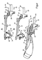
- the figure shows three longitudinal sectional views of a sliding door of an omnibus in a closing a door opening of the bus closing position, in an intermediate position and in a door opening releasing open position.
- the figure shows a sliding door 10 for a bus, which according to illustration A in a door opening of the bus occlusive closed position, according to illustration B in an intermediate position and according to illustration C in a door opening releasing open position.
- this is pivotable by a pivot lever 12 to an outside of the door opening according to a directional arrow 14, wherein the pivot lever 12 at one end about a bearing 16 with the sliding door 10 rotatable and relative to it and displaceable on the other hand via a bearing 20 at one not shown Holm of the bus is stored.
- the pivoting sliding door 10 is mounted via two bearing points 22 and 24 on a guide rail 26 of a guide device, said guide means comprises the pivot lever 12 and the guide rail 26.
- the bearing 22 has an elongated hole, which allows a displacement of the pivoting sliding door 10 according to a directional arrow 28.
- the bearing 24 includes a pivot joint, which allows rotation of the pivoting sliding door 10 according to an arrow 27 about the bearing 24.
- the bearing 16 slides at a movement of the sliding door 10 from its closed position according to illustration A in its open position according to illustration C according to a direction arrow 30 along the sliding door 10 along.
- the sliding sliding door 10 slides along the guide rail 26 of the guide device along a directional arrow 32.
- Parallel to this displacement of the sliding door 10 is pivoting the Sliding sliding door 10 according to the direction arrow 14 instead, which is made possible by the pivot lever 12.
- the pivoting lever 12 has a longitudinal region 34 which, in the closed position of the sliding sliding door 10, extends substantially perpendicular to a plane 41 extending essentially parallel to the door opening.
- the pivoting lever 12 has a second length region 36 which encloses an angle 37 of significantly smaller than 90 ° with the first longitudinal region 34, whereby the pivoting sliding door 10 in its open position as shown in FIG. C encloses an angle 40 with the plane 41 running parallel to the door opening , By this position, a collision of the sliding door 10 with an outside mirror 38 of the bus and a possible collision with a hammered front wheel desselbigen be avoided.
- the described embodiment of the bearings 22 and 24 thereby allow this movement of the sliding door 10 with simultaneous fixed mounting of the sliding door 10 on the guide rail 26th
Landscapes
- Engineering & Computer Science (AREA)
- Mechanical Engineering (AREA)
- Support Devices For Sliding Doors (AREA)
- Power-Operated Mechanisms For Wings (AREA)
Abstract
Description
- Die Erfindung betrifft eine Tür für einen Kraftwagen nach dem Oberbegriff von Patentanspruch 1.
- Bekannten Türen für Kraftwagen, insbesondere für Omnibusse, sind beispielsweise als 2-flügelige Schwenkschiebetüren ausgebildet, welche zu einer Außenseite des Kraftwagens hin ausstellbar und entlang einer korrespondierenden Türöffnung verschiebbar sind. Die bekannten Lösungen weisen allerdings den Nachteil auf, dass sie nicht in einem vorderen Bereich des Kraftwagens bzw. des Omnibusses einsetzbar sind, da die Türflügel parallel zu einer Seitenwand des Kraftwagens verschiebbar sind und zumindest ein Türflügel mit einem Außenspiegel und/oder mit einem eingeschlagenen Vorderrad des Kraftwagens kollidieren würde.
- Es ist daher Aufgabe der vorliegenden Erfindung, eine Tür für einen Kraftwagen der eingangs genannten Art derart weiter zu entwickeln, dass eine Kollision mit einem Außenspiegel und/oder mit einem Vorderrad des Kraftwagens vermeidbar ist.
- Diese Aufgabe wird durch eine Tür mit den Merkmalen des Patentanspruchs 1 gelöst. Vorteilhafte Ausgestaltungen mit zweckmäßigen und nicht-trivialen Weiterbildungen der Erfindung sind in den abhängigen Ansprüchen angegeben.
- Die erfindungsgemäße Tür, welche zwischen einer eine Türöffnung des Kraftwagens verschließenden Schließstellung und einer die Türöffnung freigegebenen Offenstellung zu einer Außenseite der Türöffnung ausstellbar und mittels einer Führungseinrichtung entlang der Türöffnung verschiebbar ist, zeichnet sich erfindungsgemäß dadurch aus, dass die Führungseinrichtung ein Führungselement umfasst, mittels welchem die Tür bei ihrer Bewegung zwischen der Schließstellung und der Offenstellung in eine Position bringbar ist, in welcher sie einen Winkel mit einer im Wesentlichen parallel zu der Türöffnung verlaufenden Ebene einschließt. Die Tür ist dabei mittels des Führungselements zumindest in ihrer Schließstellung bzw. kurz vor Erreichen dieser oder aber auch während der gesamten Bewegung in die besagte Position verbringbar, in welcher sie einen Winkel mit der genannten Ebene einschließt. Hierdurch wird beispielsweise eine Kollision der Tür mit einem Außenspiegel des Kraftwagens und/oder mit einem eingeschlagenen Rad vermieden.
- Somit ist die erfindungsgemäße Tür insbesondere als eine vordere Tür eines Omnibusses einsetzbar, bei welchem die beschriebene Problematik besonders immanent ist.
- Bei einer vorteilhaften Ausführungsform der Erfindung ist das Führungselement als schwenkbar gelagerter Schwenkhebel ausgebildet, welcher auf der einer Schiebeführung der Führungseinrichtung abgewandten Seite der Tür gelagert ist. Mit der besagten Seite der Tür ist dabei eine Breitseite gemeint, welche in Türhochrichtung verläuft. Diese Ausgestaltungsform des Führungselement erlaubt die beschriebene Position der Tür mit allen in diesem Zusammenhang bereits beschriebenen Vorteilen bei gleichzeitiger kostenunaufwendigen Herstellbarkeit der Tür, was damit auch Gesamtkosten des Kraftwagens zuträglich ist.
- Weist das Führungselement einen ersten Längenbereich auf, welcher in der Schließstellung der Tür im Wesentlichen senkrecht zu der parallel zu der Türöffnung verlaufenden Ebene verläuft, und weist das Führungselement einen zweiten Längenbereich auf, welcher einenends mit der Tür verbunden ist und welcher mit dem ersten Längenbereich einen um 180° verschiedenen Winkel, insbesondere einen Winkel kleiner als 90° einschließt, so birgt dies den Vorteil, dass das Führungselement einen nur geringen Bauraum benötigt und somit nicht sehr weit in einen Fahrgastraum des Kraftwagens hineinragt, wodurch eine negative Beeinträchtigung eines Aufenthaltsraums des Fahrgastraums, beispielsweise in Form eines Stehplatzes, vermieden ist.
- Eine weitere vorteilhafte Ausführungsform der Erfindung sieht vor, dass die Tür mittels zumindest einer Lagerstelle an einer Schiebeführung der Führungseinrichtung zur Verschiebung der Tür entlang der Türöffnung gelagert ist, welche ein Drehgelenk umfasst. Diese Lagerstelle mit dem Drehgelenk, dessen Drehachse parallel zu der besagten, parallel zur Türöffnung verlaufenden Ebene und senkrecht zu einer Verschiebungsrichtung der Tür bei deren Verbringung von der Schließstellung in die Offenstellung verläuft, erlaubt also die beschriebene Verbringung der Tür in die Position, in welcher sie einen Winkel mit der parallel zu der Tür verlaufenden Ebene einschließt. Die Lagerstelle bedeutet somit eine einfache und kostengünstige Lagerung der Tür in Folge einer geringen Teileanzahl.
- Ist die Tür mittels zumindest einer Lagerstelle an der Schiebeführung, beispielsweise einer Führungsschiene, der Führungseinrichtung gelagert, wobei diese Lagerstelle ein Langloch aufweist, so ist dies insbesondere in Zusammenhang mit der Lagerstelle mit dem Drehgelenk insofern vorteilbehaftet, als somit eine besonders stabile und damit langlebige Lagerung der Tür an der Führungsschiene möglich ist bei gleichzeitiger Darstellung der besagten Verbringung der Tür in die Position, in welcher sie einen Winkel mit der parallel zu der Tür verlaufenden Ebene einschließt. Bei Vorsehen zweier Lagerstellen, also einer Lagerstelle mit dem Drehgelenk und einer Lagerstelle mit dem Langloch, sind diese Lagerstellen in Verschiebungsrichtung der Tür voneinander beabstandet, wobei beispielsweise die näher zu dem Führungselement positionierte Lagerstelle das Langloch und dementsprechend die andere Lagerstelle das Drehgelenk umfasst.
- An dieser Stelle sei angemerkt, dass nicht nur die Tür verschiebbar an besagter Schiebeführung, insbesondere der Führungsschiene, gelagert ist, sondern dass auch das Führungselement, insbesondere der Schwenkhebel, einenends mit der Tür verbunden und relativ zu dieser verschiebbar gelagert ist, während er andernends verschwenkbar an dem Kraftwagen bzw. an einem Holm lagerbar ist.
- Die beschriebenen Vorteile der erfindungsgemäßen Tür kommen insbesondere bei einem Einsatz der Tür in Verbindung mit einer Schwenkschiebetür für einen Kraftwagen, insbesondere für einen Omnibus, zum Tragen, wobei die Schwenkschiebetür zumindest zwei Türflügel umfasst, wobei zumindest einer der Türflügel als eine erfindungsgemäße Tür ausgebildet ist. Gerade bei einem Einsatz dieser Schwenkschiebetür als vordere Einstiegstür des Omnibusses ist insbesondere die Ausbildung des Türflügels, welcher näher zu einem Außenspiegel des Omnibusses positioniert ist, als erfindungsgemäße Tür vorteilbehaftet, da dadurch eine Kollision mit dem Außenspiegel und/oder mit einem eingeschlagenen Rad des Omnibusses vermeidbar ist.
- Weitere Vorteile, Merkmale und Einzelheiten der Erfindung ergeben sich aus der nachfolgenden Beschreibung eines bevorzugten Ausführungsbeispiels sowie anhand der Zeichnung.
- Die vorstehend in der Beschreibung genannten Merkmale und Merkmalskombinationen sowie die nachfolgend in der Figurenbeschreibung genannten und/oder in der Figur alleine gezeigten Merkmale und Merkmalskombinationen sind nicht nur in der jeweils angegebenen Kombination, sondern auch in anderen Kombinationen oder in Alleinstellung verwendbar, ohne den Rahmen der Erfindung zu verlassen.
- Die Figur zeigt drei Längsschnittansichten einer Schwenkschiebetür eines Omnibusses in einer eine Türöffnung des Omnibusses verschließenden Schließposition, in einer Zwischenposition und in einer die Türöffnung freigebenden Offenposition.
- Die Figur zeigt eine Schwenkschiebetür 10 für einen Omnibus, welche sich gemäß Darstellung A in einer eine Türöffnung des Omnibusses verschließenden Schließstellung, gemäß Darstellung B in einer Zwischenstellung und gemäß Darstellung C in einer die Türöffnung freigebenden Offenstellung befindet.
- Zur Verbringung der Schwenkschiebetür 10 ist diese durch einen Schwenkhebel 12 zu einer Außenseite der Türöffnung gemäß einem Richtungspfeil 14 hin verschwenkbar, wobei der Schwenkhebel 12 einenends über eine Lagerstelle 16 mit der Schwenkschiebetür 10 drehbar und relativ zu ihr verschiebbar und andernends über eine Lagerstelle 20 an einem nicht dargestellten Holm des Omnibusses gelagert ist.
- Die Schwenkschiebetür 10 ist über zwei Lagerstellen 22 und 24 an einer Führungsschiene 26 einer Führungseinrichtung gelagert, wobei diese Führungseinrichtung den Schwenkhebel 12 sowie die Führungsschiene 26 umfasst.
- Die Lagerstelle 22 weist ein Langloch auf, welches eine Verschiebung der Schwenkschiebetür 10 gemäß einem Richtungspfeil 28 erlaubt. Die Lagerstelle 24 umfasst ein Drehgelenk, welches eine Drehung der Schwenkschiebetür 10 gemäß einem Pfeil 27 um die Lagerstelle 24 ermöglicht.
- Wie der Figur deutlich zu entnehmen ist, gleitet die Lagerstelle 16 bei einer Verbringung der Schwenkschiebetür 10 von ihrer Schließstellung gemäß Darstellung A in ihre Offenstellung gemäß Darstellung C gemäß einem Richtungspfeil 30 an der Schwenkschiebetür 10 entlang. Gleichzeitig gleitet die Schwenkschiebetür 10 an der Führungsschiene 26 der Führungseinrichtung gemäß einem Richtungspfeil 32 entlang. Parallel zu dieser Verschiebung der Schwenkschiebetür 10 findet ein Verschwenken der Schwenkschiebetür 10 gemäß dem Richtungspfeil 14 statt, welches durch den Schwenkhebel 12 ermöglicht wird.
- Der Schwenkhebel 12 weist einen Längenbereich 34 auf, welcher in der Schließstellung der Schwenkschiebetür 10 im Wesentlichen senkrecht zu einer im Wesentlichen parallel zu der Türöffnung verlaufenden Ebene 41 verläuft. Zudem weist der Schwenkhebel 12 einen zweiten Längenbereich 36 auf, welcher mit dem ersten Längenbereich 34 einen Winkel 37 von deutlich kleiner als 90° einschließt, wodurch die Schwenkschiebetür 10 in ihrer Offenstellung gemäß Darstellung C mit der parallel zur Türöffnung verlaufenden Ebene 41 einen Winkel 40 einschließt. Durch diese Position ist eine Kollision der Schwenkschiebetür 10 mit einem Außenspiegel 38 des Omnibusses sowie eine etwaige Kollision mit einem eingeschlagenen Vorderrad desselbigen vermeidbar. Die beschriebenen Ausführungsform der Lagerstellen 22 und 24 ermöglichen dabei diese Bewegung der Schwenkschiebetür 10 bei gleichzeitiger fester Lagerung der Schwenkschiebetür 10 an der Führungsschiene 26.
Claims (6)
- Tür (10), insbesondere Schwenkschiebetür (10), für einen Kraftwagen, welche zwischen einer eine Türöffnung des Kraftwagens verschließenden Schließstellung und einer die Türöffnung freigebenden Offenstellung zu einer Außenseite der Türöffnung hin ausstellbar und mittels einer Führungseinrichtung entlang der Türöffnung verschiebbar ist,
dadurch gekennzeichnet, dass
die Führungseinrichtung ein Führungselement (12) umfasst, mittels welchem die Tür (10) bei ihrer Bewegung zwischen der Schließstellung und der Offenstellung in eine Position bringbar ist, in welcher sie einen Winkel (40) mit einer parallel zu der Türöffnung verlaufenden Ebene (41) einschließt. - Tür (10) nach Anspruch 1,
dadurch gekennzeichnet, dass
das Führungselement (12) als schwenkbar gelagerter Schwenkhebel (12) ausgebildet ist, welcher auf der einer Schiebeführung (26) der Führungseinrichtung abgewandten Seite der Tür (10) gelagert ist. - Tür (10) nach eine der Ansprüche 1 oder 2,
dadurch gekennzeichnet, dass
das Führungselement (12) einen ersten Längenbereich (34) aufweist, welcher in der Schließstellung der Tür (10) im Wesentlichen senkrecht zu der parallel zu der Türöffnung verlaufenden Ebene (41) verläuft, und welcher einen zweiten Längebereich (36) aufweist, welcher einenends mit der Tür (10) verbunden ist und welcher mit dem ersten Längenbereich (34) einen von 180° verschiedenen Winkel (37), insbesondere einen Winkel (37) kleiner als 90°, einschließt. - Tür (10) nach einem der vorhergehenden Ansprüche,
dadurch gekennzeichnet, dass
die Tür (10) mittels zumindest einer Lagerstelle (24) an einer Schiebeführung (26) der Führungseinrichtung gelagert ist, welche ein Drehgelenk umfasst - Tür (10) nach einem der vorhergehenden Ansprüche,
dadurch gekennzeichnet, dass
die Tür (10) mittels zumindest einer Lagerstelle (22) an einer Schiebeführung (26) der Führungseinrichtung gelagert ist, welche ein Langloch aufweist. - Schwenkschiebetür für einen Kraftwagen, insbesondere einen Omnibus, mit zumindest zwei Türflügeln, wobei zumindest einer der Türflügeln als eine Tür (10) nach einem der vorhergehenden Ansprüche ausgebildet ist.
Applications Claiming Priority (1)
| Application Number | Priority Date | Filing Date | Title |
|---|---|---|---|
| DE200910032864 DE102009032864A1 (de) | 2009-07-14 | 2009-07-14 | Tür für einen Kraftwagen |
Publications (3)
| Publication Number | Publication Date |
|---|---|
| EP2275295A2 true EP2275295A2 (de) | 2011-01-19 |
| EP2275295A3 EP2275295A3 (de) | 2013-04-17 |
| EP2275295B1 EP2275295B1 (de) | 2018-12-19 |
Family
ID=42990931
Family Applications (1)
| Application Number | Title | Priority Date | Filing Date |
|---|---|---|---|
| EP10006487.2A Active EP2275295B1 (de) | 2009-07-14 | 2010-06-22 | Tür für einen Kraftwagen |
Country Status (2)
| Country | Link |
|---|---|
| EP (1) | EP2275295B1 (de) |
| DE (1) | DE102009032864A1 (de) |
Family Cites Families (7)
| Publication number | Priority date | Publication date | Assignee | Title |
|---|---|---|---|---|
| US3982601A (en) * | 1975-05-01 | 1976-09-28 | Deere & Company | Guide support for slidable door of grader having an articulated frame |
| DE19735181C2 (de) * | 1997-08-14 | 2001-11-15 | Webasto Tuersysteme Gmbh | Schwenkschiebetür für Fahrzeuge |
| DE19901016B4 (de) * | 1999-01-13 | 2004-07-08 | Eller Gmbh | Nutzfahrzeug |
| FR2804380B1 (fr) * | 2000-02-02 | 2002-04-05 | Renault | Systeme de charnieres pour porte de coffre de vehicule automobile comportant un bras articule et un bras coulissant |
| FR2827627B1 (fr) * | 2001-07-18 | 2004-01-23 | Mecalac | Dispositif d'ouverture et de fermeture d'une porte, porte et vehicule a moteur equipe d'une telle porte |
| CA2489097C (en) * | 2002-06-11 | 2011-06-14 | Peter Lance Oxley | Vehicle door with pivot arm |
| FR2891571B1 (fr) * | 2005-09-30 | 2009-04-24 | Lecapitaine Soc Par Actions Si | Ensemble a porte coulissante et camion correspondant. |
-
2009
- 2009-07-14 DE DE200910032864 patent/DE102009032864A1/de not_active Withdrawn
-
2010
- 2010-06-22 EP EP10006487.2A patent/EP2275295B1/de active Active
Non-Patent Citations (1)
| Title |
|---|
| None |
Also Published As
| Publication number | Publication date |
|---|---|
| EP2275295A3 (de) | 2013-04-17 |
| DE102009032864A1 (de) | 2011-01-20 |
| EP2275295B1 (de) | 2018-12-19 |
Similar Documents
| Publication | Publication Date | Title |
|---|---|---|
| EP1853474B1 (de) | Schwenkschiebetür | |
| EP1721768B1 (de) | Schiebetüre für ein Kraftfahrzeug | |
| WO2019115065A1 (de) | Türgriffanordnung einer fahrzeugtür | |
| DE102017130029A1 (de) | Türgriffanordnung einer Fahrzeugtür | |
| EP3161234B1 (de) | Laufwagenanordnung mit einer federausnehmung sowie schiebetür oder schiebefenster mit einer solchen laufwagenanordnung | |
| DE10025925B4 (de) | Seitentür eines Kraftfahrzeugs | |
| WO2008064650A2 (de) | Türschloss für türen von luftfahrzeugen, insbesondere von hubschraubern | |
| EP2329975B1 (de) | Schiebetüre für ein Fahrzeug | |
| EP1813750A2 (de) | Tür-, Fenster-, Klappenanordnung oder dergleichen an dem Wohnaufbau eines Reisemobils oder an einem Wohnwagen | |
| EP2275295B1 (de) | Tür für einen Kraftwagen | |
| DE102005012419B4 (de) | Lagerbügel eines Außengriffes einer Fahrzeugtür für Kraftfahrzeuge | |
| DE102007035230A1 (de) | Schiebetüre für ein Fahrzeug | |
| DE102010023731A1 (de) | Sperreinrichtung für ein in einer Fahrzeugtüre eines Kraftfahrzeugs schwenkbar angeordneten Bauteils | |
| EP2072341B1 (de) | Antriebseinheit in einem Kraftfahrzeug | |
| EP4403434A1 (de) | Innenschiebetür für ein schienenfahrzeug mit einfahrbarer abdeckung | |
| EP1614844A2 (de) | Drehlagervorrichtung | |
| EP3296492A1 (de) | Führungssystem für eine schiebetür sowie schiebetür mit einem führungssystem und entsprechend ausgestattetes kraftfahrzeug | |
| DE102010019548A1 (de) | Mehrgelenkscharnier | |
| EP1862623A1 (de) | Schwenksicherung | |
| DE102013003672A1 (de) | Fahrzeug mit einem Haubenelement | |
| DE102017210116A1 (de) | Türgriffsystem für eine Kraftfahrzeugtür | |
| DE10318237B3 (de) | Weitwinkel-Scharnier für ein Kraftfahrzeug mit seitlich aufschwenkbarer Hecktür | |
| DE102004060501B4 (de) | Vorrichtung zur Positionierung eines Teiles | |
| DE102022131211A1 (de) | Luftzufuhrvorrichtung einer Kraftfahrzeugkarosserie eines Kraftfahrzeugs | |
| DE102012004818A1 (de) | Fahrzeugtür, welche als Schiebetüre aufgeschoben und als Schwenktüre aufgeschwenkt werden kann |
Legal Events
| Date | Code | Title | Description |
|---|---|---|---|
| PUAI | Public reference made under article 153(3) epc to a published international application that has entered the european phase |
Free format text: ORIGINAL CODE: 0009012 |
|
| AK | Designated contracting states |
Kind code of ref document: A2 Designated state(s): AL AT BE BG CH CY CZ DE DK EE ES FI FR GB GR HR HU IE IS IT LI LT LU LV MC MK MT NL NO PL PT RO SE SI SK SM TR |
|
| AX | Request for extension of the european patent |
Extension state: BA ME RS |
|
| PUAL | Search report despatched |
Free format text: ORIGINAL CODE: 0009013 |
|
| AK | Designated contracting states |
Kind code of ref document: A3 Designated state(s): AL AT BE BG CH CY CZ DE DK EE ES FI FR GB GR HR HU IE IS IT LI LT LU LV MC MK MT NL NO PL PT RO SE SI SK SM TR |
|
| AX | Request for extension of the european patent |
Extension state: BA ME RS |
|
| RIC1 | Information provided on ipc code assigned before grant |
Ipc: B60J 5/06 20060101AFI20130312BHEP Ipc: B60J 5/04 20060101ALI20130312BHEP |
|
| 17P | Request for examination filed |
Effective date: 20140203 |
|
| RBV | Designated contracting states (corrected) |
Designated state(s): AL AT BE BG CH CY CZ DE DK EE ES FI FR GB GR HR HU IE IS IT LI LT LU LV MC MK MT NL NO PL PT RO SE SI SK SM TR |
|
| 17Q | First examination report despatched |
Effective date: 20140611 |
|
| GRAP | Despatch of communication of intention to grant a patent |
Free format text: ORIGINAL CODE: EPIDOSNIGR1 |
|
| STAA | Information on the status of an ep patent application or granted ep patent |
Free format text: STATUS: GRANT OF PATENT IS INTENDED |
|
| INTG | Intention to grant announced |
Effective date: 20180525 |
|
| GRAS | Grant fee paid |
Free format text: ORIGINAL CODE: EPIDOSNIGR3 |
|
| GRAA | (expected) grant |
Free format text: ORIGINAL CODE: 0009210 |
|
| STAA | Information on the status of an ep patent application or granted ep patent |
Free format text: STATUS: THE PATENT HAS BEEN GRANTED |
|
| AK | Designated contracting states |
Kind code of ref document: B1 Designated state(s): AL AT BE BG CH CY CZ DE DK EE ES FI FR GB GR HR HU IE IS IT LI LT LU LV MC MK MT NL NO PL PT RO SE SI SK SM TR |
|
| REG | Reference to a national code |
Ref country code: GB Ref legal event code: FG4D Free format text: NOT ENGLISH |
|
| REG | Reference to a national code |
Ref country code: CH Ref legal event code: EP |
|
| REG | Reference to a national code |
Ref country code: IE Ref legal event code: FG4D Free format text: LANGUAGE OF EP DOCUMENT: GERMAN |
|
| REG | Reference to a national code |
Ref country code: DE Ref legal event code: R096 Ref document number: 502010015638 Country of ref document: DE |
|
| REG | Reference to a national code |
Ref country code: AT Ref legal event code: REF Ref document number: 1078302 Country of ref document: AT Kind code of ref document: T Effective date: 20190115 |
|
| REG | Reference to a national code |
Ref country code: NL Ref legal event code: MP Effective date: 20181219 |
|
| PG25 | Lapsed in a contracting state [announced via postgrant information from national office to epo] |
Ref country code: BG Free format text: LAPSE BECAUSE OF FAILURE TO SUBMIT A TRANSLATION OF THE DESCRIPTION OR TO PAY THE FEE WITHIN THE PRESCRIBED TIME-LIMIT Effective date: 20190319 Ref country code: NO Free format text: LAPSE BECAUSE OF FAILURE TO SUBMIT A TRANSLATION OF THE DESCRIPTION OR TO PAY THE FEE WITHIN THE PRESCRIBED TIME-LIMIT Effective date: 20190319 Ref country code: HR Free format text: LAPSE BECAUSE OF FAILURE TO SUBMIT A TRANSLATION OF THE DESCRIPTION OR TO PAY THE FEE WITHIN THE PRESCRIBED TIME-LIMIT Effective date: 20181219 Ref country code: LT Free format text: LAPSE BECAUSE OF FAILURE TO SUBMIT A TRANSLATION OF THE DESCRIPTION OR TO PAY THE FEE WITHIN THE PRESCRIBED TIME-LIMIT Effective date: 20181219 Ref country code: LV Free format text: LAPSE BECAUSE OF FAILURE TO SUBMIT A TRANSLATION OF THE DESCRIPTION OR TO PAY THE FEE WITHIN THE PRESCRIBED TIME-LIMIT Effective date: 20181219 Ref country code: FI Free format text: LAPSE BECAUSE OF FAILURE TO SUBMIT A TRANSLATION OF THE DESCRIPTION OR TO PAY THE FEE WITHIN THE PRESCRIBED TIME-LIMIT Effective date: 20181219 |
|
| REG | Reference to a national code |
Ref country code: LT Ref legal event code: MG4D |
|
| PG25 | Lapsed in a contracting state [announced via postgrant information from national office to epo] |
Ref country code: GR Free format text: LAPSE BECAUSE OF FAILURE TO SUBMIT A TRANSLATION OF THE DESCRIPTION OR TO PAY THE FEE WITHIN THE PRESCRIBED TIME-LIMIT Effective date: 20190320 Ref country code: AL Free format text: LAPSE BECAUSE OF FAILURE TO SUBMIT A TRANSLATION OF THE DESCRIPTION OR TO PAY THE FEE WITHIN THE PRESCRIBED TIME-LIMIT Effective date: 20181219 Ref country code: SE Free format text: LAPSE BECAUSE OF FAILURE TO SUBMIT A TRANSLATION OF THE DESCRIPTION OR TO PAY THE FEE WITHIN THE PRESCRIBED TIME-LIMIT Effective date: 20181219 |
|
| PG25 | Lapsed in a contracting state [announced via postgrant information from national office to epo] |
Ref country code: NL Free format text: LAPSE BECAUSE OF FAILURE TO SUBMIT A TRANSLATION OF THE DESCRIPTION OR TO PAY THE FEE WITHIN THE PRESCRIBED TIME-LIMIT Effective date: 20181219 |
|
| PG25 | Lapsed in a contracting state [announced via postgrant information from national office to epo] |
Ref country code: PL Free format text: LAPSE BECAUSE OF FAILURE TO SUBMIT A TRANSLATION OF THE DESCRIPTION OR TO PAY THE FEE WITHIN THE PRESCRIBED TIME-LIMIT Effective date: 20181219 Ref country code: IT Free format text: LAPSE BECAUSE OF FAILURE TO SUBMIT A TRANSLATION OF THE DESCRIPTION OR TO PAY THE FEE WITHIN THE PRESCRIBED TIME-LIMIT Effective date: 20181219 Ref country code: ES Free format text: LAPSE BECAUSE OF FAILURE TO SUBMIT A TRANSLATION OF THE DESCRIPTION OR TO PAY THE FEE WITHIN THE PRESCRIBED TIME-LIMIT Effective date: 20181219 Ref country code: CZ Free format text: LAPSE BECAUSE OF FAILURE TO SUBMIT A TRANSLATION OF THE DESCRIPTION OR TO PAY THE FEE WITHIN THE PRESCRIBED TIME-LIMIT Effective date: 20181219 Ref country code: PT Free format text: LAPSE BECAUSE OF FAILURE TO SUBMIT A TRANSLATION OF THE DESCRIPTION OR TO PAY THE FEE WITHIN THE PRESCRIBED TIME-LIMIT Effective date: 20190419 |
|
| PG25 | Lapsed in a contracting state [announced via postgrant information from national office to epo] |
Ref country code: IS Free format text: LAPSE BECAUSE OF FAILURE TO SUBMIT A TRANSLATION OF THE DESCRIPTION OR TO PAY THE FEE WITHIN THE PRESCRIBED TIME-LIMIT Effective date: 20190419 Ref country code: SK Free format text: LAPSE BECAUSE OF FAILURE TO SUBMIT A TRANSLATION OF THE DESCRIPTION OR TO PAY THE FEE WITHIN THE PRESCRIBED TIME-LIMIT Effective date: 20181219 Ref country code: RO Free format text: LAPSE BECAUSE OF FAILURE TO SUBMIT A TRANSLATION OF THE DESCRIPTION OR TO PAY THE FEE WITHIN THE PRESCRIBED TIME-LIMIT Effective date: 20181219 Ref country code: SM Free format text: LAPSE BECAUSE OF FAILURE TO SUBMIT A TRANSLATION OF THE DESCRIPTION OR TO PAY THE FEE WITHIN THE PRESCRIBED TIME-LIMIT Effective date: 20181219 Ref country code: EE Free format text: LAPSE BECAUSE OF FAILURE TO SUBMIT A TRANSLATION OF THE DESCRIPTION OR TO PAY THE FEE WITHIN THE PRESCRIBED TIME-LIMIT Effective date: 20181219 |
|
| REG | Reference to a national code |
Ref country code: DE Ref legal event code: R097 Ref document number: 502010015638 Country of ref document: DE |
|
| PLBE | No opposition filed within time limit |
Free format text: ORIGINAL CODE: 0009261 |
|
| STAA | Information on the status of an ep patent application or granted ep patent |
Free format text: STATUS: NO OPPOSITION FILED WITHIN TIME LIMIT |
|
| PG25 | Lapsed in a contracting state [announced via postgrant information from national office to epo] |
Ref country code: DK Free format text: LAPSE BECAUSE OF FAILURE TO SUBMIT A TRANSLATION OF THE DESCRIPTION OR TO PAY THE FEE WITHIN THE PRESCRIBED TIME-LIMIT Effective date: 20181219 |
|
| 26N | No opposition filed |
Effective date: 20190920 |
|
| PG25 | Lapsed in a contracting state [announced via postgrant information from national office to epo] |
Ref country code: MC Free format text: LAPSE BECAUSE OF FAILURE TO SUBMIT A TRANSLATION OF THE DESCRIPTION OR TO PAY THE FEE WITHIN THE PRESCRIBED TIME-LIMIT Effective date: 20181219 |
|
| REG | Reference to a national code |
Ref country code: CH Ref legal event code: PL |
|
| GBPC | Gb: european patent ceased through non-payment of renewal fee |
Effective date: 20190622 |
|
| PG25 | Lapsed in a contracting state [announced via postgrant information from national office to epo] |
Ref country code: SI Free format text: LAPSE BECAUSE OF FAILURE TO SUBMIT A TRANSLATION OF THE DESCRIPTION OR TO PAY THE FEE WITHIN THE PRESCRIBED TIME-LIMIT Effective date: 20181219 |
|
| REG | Reference to a national code |
Ref country code: BE Ref legal event code: MM Effective date: 20190630 |
|
| PG25 | Lapsed in a contracting state [announced via postgrant information from national office to epo] |
Ref country code: TR Free format text: LAPSE BECAUSE OF FAILURE TO SUBMIT A TRANSLATION OF THE DESCRIPTION OR TO PAY THE FEE WITHIN THE PRESCRIBED TIME-LIMIT Effective date: 20181219 |
|
| PG25 | Lapsed in a contracting state [announced via postgrant information from national office to epo] |
Ref country code: IE Free format text: LAPSE BECAUSE OF NON-PAYMENT OF DUE FEES Effective date: 20190622 Ref country code: GB Free format text: LAPSE BECAUSE OF NON-PAYMENT OF DUE FEES Effective date: 20190622 |
|
| PG25 | Lapsed in a contracting state [announced via postgrant information from national office to epo] |
Ref country code: LI Free format text: LAPSE BECAUSE OF NON-PAYMENT OF DUE FEES Effective date: 20190630 Ref country code: LU Free format text: LAPSE BECAUSE OF NON-PAYMENT OF DUE FEES Effective date: 20190622 Ref country code: CH Free format text: LAPSE BECAUSE OF NON-PAYMENT OF DUE FEES Effective date: 20190630 Ref country code: BE Free format text: LAPSE BECAUSE OF NON-PAYMENT OF DUE FEES Effective date: 20190630 |
|
| PG25 | Lapsed in a contracting state [announced via postgrant information from national office to epo] |
Ref country code: FR Free format text: LAPSE BECAUSE OF NON-PAYMENT OF DUE FEES Effective date: 20190630 |
|
| REG | Reference to a national code |
Ref country code: AT Ref legal event code: MM01 Ref document number: 1078302 Country of ref document: AT Kind code of ref document: T Effective date: 20190622 |
|
| REG | Reference to a national code |
Ref country code: DE Ref legal event code: R081 Ref document number: 502010015638 Country of ref document: DE Owner name: DAIMLER TRUCK AG, DE Free format text: FORMER OWNER: DAIMLER AG, 70327 STUTTGART, DE Ref country code: DE Ref legal event code: R082 Ref document number: 502010015638 Country of ref document: DE Representative=s name: JENSEN & SON, GB Ref country code: DE Ref legal event code: R081 Ref document number: 502010015638 Country of ref document: DE Owner name: DAIMLER AG, DE Free format text: FORMER OWNER: DAIMLER AG, 70327 STUTTGART, DE Ref country code: DE Ref legal event code: R082 Ref document number: 502010015638 Country of ref document: DE Representative=s name: JENSENS IP LIMITED, IE |
|
| PG25 | Lapsed in a contracting state [announced via postgrant information from national office to epo] |
Ref country code: AT Free format text: LAPSE BECAUSE OF NON-PAYMENT OF DUE FEES Effective date: 20190622 |
|
| REG | Reference to a national code |
Ref country code: DE Ref legal event code: R082 Ref document number: 502010015638 Country of ref document: DE Representative=s name: JENSENS IP LIMITED, IE |
|
| PG25 | Lapsed in a contracting state [announced via postgrant information from national office to epo] |
Ref country code: CY Free format text: LAPSE BECAUSE OF FAILURE TO SUBMIT A TRANSLATION OF THE DESCRIPTION OR TO PAY THE FEE WITHIN THE PRESCRIBED TIME-LIMIT Effective date: 20181219 |
|
| PG25 | Lapsed in a contracting state [announced via postgrant information from national office to epo] |
Ref country code: MT Free format text: LAPSE BECAUSE OF FAILURE TO SUBMIT A TRANSLATION OF THE DESCRIPTION OR TO PAY THE FEE WITHIN THE PRESCRIBED TIME-LIMIT Effective date: 20181219 Ref country code: HU Free format text: LAPSE BECAUSE OF FAILURE TO SUBMIT A TRANSLATION OF THE DESCRIPTION OR TO PAY THE FEE WITHIN THE PRESCRIBED TIME-LIMIT; INVALID AB INITIO Effective date: 20100622 |
|
| REG | Reference to a national code |
Ref country code: DE Ref legal event code: R081 Ref document number: 502010015638 Country of ref document: DE Owner name: DAIMLER TRUCK AG, DE Free format text: FORMER OWNER: DAIMLER AG, STUTTGART, DE |
|
| PG25 | Lapsed in a contracting state [announced via postgrant information from national office to epo] |
Ref country code: MK Free format text: LAPSE BECAUSE OF FAILURE TO SUBMIT A TRANSLATION OF THE DESCRIPTION OR TO PAY THE FEE WITHIN THE PRESCRIBED TIME-LIMIT Effective date: 20181219 |
|
| P01 | Opt-out of the competence of the unified patent court (upc) registered |
Effective date: 20230609 |
|
| PGFP | Annual fee paid to national office [announced via postgrant information from national office to epo] |
Ref country code: DE Payment date: 20250626 Year of fee payment: 16 |