EP2274058B1 - Integrated belt and plenum powered air purifying respirator - Google Patents
Integrated belt and plenum powered air purifying respirator Download PDFInfo
- Publication number
- EP2274058B1 EP2274058B1 EP09743756.0A EP09743756A EP2274058B1 EP 2274058 B1 EP2274058 B1 EP 2274058B1 EP 09743756 A EP09743756 A EP 09743756A EP 2274058 B1 EP2274058 B1 EP 2274058B1
- Authority
- EP
- European Patent Office
- Prior art keywords
- papr
- belt
- belt body
- air purifying
- purifying respirator
- Prior art date
- Legal status (The legal status is an assumption and is not a legal conclusion. Google has not performed a legal analysis and makes no representation as to the accuracy of the status listed.)
- Active
Links
- 230000029058 respiratory gaseous exchange Effects 0.000 claims description 10
- 238000004891 communication Methods 0.000 claims description 5
- 239000007789 gas Substances 0.000 claims description 3
- 239000013618 particulate matter Substances 0.000 claims description 3
- 230000014759 maintenance of location Effects 0.000 claims description 2
- 239000000126 substance Substances 0.000 claims description 2
- 239000013536 elastomeric material Substances 0.000 claims 1
- 239000003570 air Substances 0.000 description 57
- 239000000463 material Substances 0.000 description 15
- 239000012080 ambient air Substances 0.000 description 10
- 238000001914 filtration Methods 0.000 description 9
- 230000000717 retained effect Effects 0.000 description 4
- 239000012530 fluid Substances 0.000 description 3
- 230000036571 hydration Effects 0.000 description 3
- 238000006703 hydration reaction Methods 0.000 description 3
- 238000007726 management method Methods 0.000 description 3
- 238000000034 method Methods 0.000 description 3
- 230000000241 respiratory effect Effects 0.000 description 3
- 230000008901 benefit Effects 0.000 description 2
- 125000000484 butyl group Chemical group [H]C([*])([H])C([H])([H])C([H])([H])C([H])([H])[H] 0.000 description 2
- 238000010276 construction Methods 0.000 description 2
- 238000005202 decontamination Methods 0.000 description 2
- 230000003588 decontaminative effect Effects 0.000 description 2
- 230000001419 dependent effect Effects 0.000 description 2
- 239000000203 mixture Substances 0.000 description 2
- 229920001296 polysiloxane Polymers 0.000 description 2
- 238000004659 sterilization and disinfection Methods 0.000 description 2
- 239000000853 adhesive Substances 0.000 description 1
- 230000001070 adhesive effect Effects 0.000 description 1
- 230000002411 adverse Effects 0.000 description 1
- QVGXLLKOCUKJST-UHFFFAOYSA-N atomic oxygen Chemical compound [O] QVGXLLKOCUKJST-UHFFFAOYSA-N 0.000 description 1
- 238000005452 bending Methods 0.000 description 1
- 230000008859 change Effects 0.000 description 1
- 238000004140 cleaning Methods 0.000 description 1
- 230000006835 compression Effects 0.000 description 1
- 238000007906 compression Methods 0.000 description 1
- 238000009826 distribution Methods 0.000 description 1
- 231100001261 hazardous Toxicity 0.000 description 1
- 238000009434 installation Methods 0.000 description 1
- 230000007246 mechanism Effects 0.000 description 1
- 239000002184 metal Substances 0.000 description 1
- 230000004048 modification Effects 0.000 description 1
- 238000012986 modification Methods 0.000 description 1
- 239000001301 oxygen Substances 0.000 description 1
- 229910052760 oxygen Inorganic materials 0.000 description 1
- 239000011236 particulate material Substances 0.000 description 1
- 239000004033 plastic Substances 0.000 description 1
- 230000008569 process Effects 0.000 description 1
- 230000008439 repair process Effects 0.000 description 1
- 230000004044 response Effects 0.000 description 1
- 238000003860 storage Methods 0.000 description 1
- 238000003466 welding Methods 0.000 description 1
Images


Classifications
-
- A—HUMAN NECESSITIES
- A62—LIFE-SAVING; FIRE-FIGHTING
- A62B—DEVICES, APPARATUS OR METHODS FOR LIFE-SAVING
- A62B7/00—Respiratory apparatus
- A62B7/10—Respiratory apparatus with filter elements
-
- A—HUMAN NECESSITIES
- A62—LIFE-SAVING; FIRE-FIGHTING
- A62B—DEVICES, APPARATUS OR METHODS FOR LIFE-SAVING
- A62B9/00—Component parts for respiratory or breathing apparatus
- A62B9/04—Couplings; Supporting frames
-
- A—HUMAN NECESSITIES
- A62—LIFE-SAVING; FIRE-FIGHTING
- A62B—DEVICES, APPARATUS OR METHODS FOR LIFE-SAVING
- A62B18/00—Breathing masks or helmets, e.g. affording protection against chemical agents or for use at high altitudes or incorporating a pump or compressor for reducing the inhalation effort
- A62B18/006—Breathing masks or helmets, e.g. affording protection against chemical agents or for use at high altitudes or incorporating a pump or compressor for reducing the inhalation effort with pumps for forced ventilation
Definitions
- the invention relates to powered air purifying respirators.
- the invention relates to a powered air purifying respirator that has an integrated plenum and belt.
- the invention relates to a powered air purifying respirator that has a powered air supply source that is adapted to be worn around the waist.
- the invention relates to a powered air purifying respirator component that is adapted to be removably mounted to a hose that is connected to a respirator mask.
- the invention relates to a powered air purifying respirator component that delivers a constant flow of purified air to a respirator mask in the event of partial filter clogging.
- the invention relates to a kit for a powered air purifying respirator that is adapted for multiple different conditions.
- PAPRs Powered air-purifying respirators
- PAPRs continually supply positive air pressure to a respirator mask to maintain positive pressure in the respirator.
- PAPRs are generally used in military, industrial or hazardous environments to provide personal respiratory protection by preventing ambient air from entering the user's mask, helmet, or hood. Respiratory hazards can include particulate matter, harmful gases, or vapors, which are removed by passing ambient air through the PAPR.
- a PAPR includes a powered fan that forces ambient air through one or more filters for delivery to an inlet opening in the respirator mask, helmet or hood.
- the fan, filter, and power source may be mounted on a face mask or, in some cases, may be mounted on a belt or backpack and connected to the facemask through a hose and a fan.
- PAPRs that are worn on the user's waist are typically attached to a belt by threading the belt through loops or slots in the component housing, and the respiratory components are typically worn on the back portion of the belt.
- a PAPR that includes an enclosure, defining a single contiguous enclosed interior, an inlet duct, including an inlet and a distribution portion, that guides ambient air to the interior of the enclosure, a plurality of filter canisters disposed within the interior of the enclosure, and a blower that forces air through the at least one inlet, into the interior of the enclosure and through the plurality of filter canisters to produce filtered air suitable for breathing.
- the main body of the PAPR is the PAPR housing, which encloses the motor, the blower and at least part of the controller.
- the PAPR housing provides the primary structure of the PAPR and includes one or more ports for the filter canisters.
- Each armored filter includes a filter canister and a filter cover. Together, the filter covers and manifolds form enclosures that protect the filter canisters from heat, flame, physical blows, etc.
- the PAPR can be carried by the users around their waist via a belt, or on their back or over their shoulder using a simple conventional shoulder strap or harness, or any other suitable apparatus.
- United States Patent Application Publication No. 2006/0191533 to Brookman et al discloses a combination SCBA system for providing bottled air and PAPR system for purifying ambient air for use by a user wherein the two systems are used alternatingly depending on the contaminated condition of the ambient air and the oxygen content of the ambient air.
- the blower motor and fan assembly is operatively connected to a plenum chamber assembly that has attached to it a plurality of filter elements.
- the impeller fan draws ambient air through the filters.
- the cleaned air is drawn by the fan into operative relationship with the face mask and thereby provides breathable air to the wearer.
- the system is worn on a conventional harness.
- United States Patent No. 4,478,216 to Dukowski discloses a portable breathing assist, including a two part external housing comprising a first half and a second half.
- the breathing assist further includes an internal scroll housing with a radial impeller within the scroll housing; the radial impeller is mounted so as to be rotatable by the electric motor shaft to which it is attached.
- An air manifold within the external housing defines a passageway for air from two openings to a central inlet into the internal scroll housing.
- the air passageway communicates with a plenum which communicates directly with a circular threaded opening adapted to receive a filter pad.
- the first housing half has brackets for threading a belt therethrough; the belt is said to secure the device around the waist of the user.
- the first housing half also contains a battery pack.
- the portable breathing assist is said to be used in conjunction with a face mask and hose.
- CA 2,427,443 A1 describes an air disinfection system.
- the air disinfection system includes a breathing mask connected to a filter tube via another tube.
- the filter tube has an opening at each end which is covered by a filter.
- Various filtration mechanisms may be located inside the tube, depending on the necessary degree of protection.
- a battery pack, controller and motor are attached to a side of the filter tube.
- WO 2009/067583 A2 representing prior art pursuant to Article 54(3) EPC discloses an air purifying respirator kit comprising: an elongated hollow belt body; and at least one filter for supplying purified air to the interior of the belt body; wherein: the belt body has multiple openings along its length;the at least one filter is a filter canister, the filter canister being adapted to be mounted in at least one of the multiple openings; and the air purifying respirator kit further includes: a self-contained powered air purifying respirator (PAPR) module that includes a motor, a fan, a power source, an inlet and an outlet, wherein the PAPR module is configured to be mounted in one of the multiple openings and wherein, when the filter canister is mounted in one of the multiple openings and the PAPR module is mounted in another one of the multiple openings, the inlet is in communication with the filter canister and the outlet is arranged to supply purified air to a user; and a pair of end caps.
- PAPR self-contained powered air pur
- the PAPR belt 10 generally comprises a belt body 12, a spine 60, a motor 14 and a driven fan 16 encased within a blower housing 24, and a power source 20 encased in a battery housing 26.
- the blower housing 24 and battery housing 26 are attached to opposite ends of the flexible belt body 12.
- the PAPR belt 10 has at least one inlet opening 28 that can be attached to an air filtering means, and an outlet 30 that can be attached to a user- wearable respiration protection device.
- the PAPR belt 10 comprises three inlet openings 28.
- the PAPR belt 10 forms a portion of a belt or bandolier to be worn around the user's waist, back, or other location, and at least the belt body 12 can be made of a flexible rubber material, such as a Butyl and Silicone blend, or any other suitable material to allow the PAPR belt 10 to conform to the user's body.
- a flexible rubber material such as a Butyl and Silicone blend, or any other suitable material to allow the PAPR belt 10 to conform to the user's body.
- the PAPR belt body 12 is hollow, and can have any cross-sectional configuration, but is preferably rectangular.
- the belt body 12 is comprised of a center segment 34, a battery end 38, and a blower end 36.
- the center segment 34 has a plurality of relatively flat sections 41 bounded by corrugated sections 42.
- the corrugated sections 42 provide longitudinal as well as lateral flexibility to the belt body so that it can be compressed longitudinally slightly and can bend laterally for conforming to the body of a user.
- Disposed in each of the three flat sections 41 is an opening in which a filter mount 106 is installed.
- the filter mount 106 includes an internally threaded filter sleeve 40 that defines the inlet opening 28 of the PAPR belt 10 and that can be used to couple an air filtering canister or other suitable filter to the PAPR belt 10.
- the belt body 12 acts as an air flow plenum that fluidly communicates the air inlet openings 28 with the air outlet 30.
- the blower housing 24 comprises a blower housing open end 44, the outlet 30, and a pair of spaced integral attaching flanges 102 forming a belt recess in the closed end.
- the outlet 30 is defined by an externally threaded hose sleeve 54, which is advantageously used to couple the PAPR belt 10 to a mask facepiece or hood (not shown) via a hose 56.
- Two attaching flanges 94, each with a pin hole 98, are integrally formed in the blower housing open end 44 and the two attaching flanges 102, each with a pin hole 48, are formed in the closed end.
- the blower housing 24 can be removably attached to the belt body 12 at the blower housing open end 44 through the pin 100 and is sealed in air-tight fashion to the blower end 36 of the belt body 12.
- the blower housing 24 can be made of the same material as the belt body 12, or any other suitable material. ends of the flexible belt body 12.
- the PAPR belt 10 has at least one inlet 28 that can be attached to an air filtering means, and an outlet 30 that can be attached to a user-wearable respiration protection device. In the illustrated embodiment, the PAPR belt 10 comprises three inlets 28.
- the PAPR belt 10 forms a portion of a belt or bandolier to be worn around the user's waist, back, or other location, and at least the belt body 12 can be made of a flexible rubber material, such as a Butyl and Silicone blend, or any other suitable material to allow the PAPR belt 10 to conform to the user's body.
- a flexible rubber material such as a Butyl and Silicone blend, or any other suitable material to allow the PAPR belt 10 to conform to the user's body.
- the PAPR belt body 12 is hollow, and can have any cross-sectional configuration, but is preferably rectangular.
- the belt body 12 is comprised of a center segment 34, a battery end 38, and a blower end 36.
- the center segment 34 has a plurality of relatively flat sections 41 bounded by corrugated sections 42.
- the corrugated sections 42 provide longitudinal as well as lateral flexibility to the belt body so that it can be compressed longitudinally slightly and can bend laterally for conforming to the body of a user.
- Disposed in each of the three flat sections 41 is an opening in which a filter mount 106 is installed.
- the filter mount 106 includes an internally threaded filter sleeve 40 that defines the inlet 28 of the PAPR belt 10 and that can be used to couple an air filtering canister or other suitable filter to the PAPR belt 10.
- the belt body 12 acts as an air flow plenum that fluidly communicates the air inlets 28 with the air outlet 30.
- the blower housing 24 comprises a blower housing open end 44, the outlet 30, and a pair of spaced integral attaching flanges 102 forming a belt recess in the closed end.
- the outlet 30 is defined by an externally threaded hose sleeve 54, which is advantageously used to couple the PAPR belt 10 to a mask facepiece or hood (not shown) via a hose 56.
- Two attaching flanges 94, each with a pin hole 98, are integrally formed in the blower housing open end 44 and the two attaching flanges 102, each with a pin hole 48, are formed in the closed end.
- the blower housing 24 can be removably attached to the belt body 12 at the blower housing open end 44 through the pin 100 and is sealed in air-tight fashion to the blower end 36 of the belt body 12.
- the blower housing 24 can be made of the same material as the belt body 12, or any other suitable material.
- the battery housing 26 encases the power source 20 and comprises a battery housing open end 46 and a pair of integral attaching flanges 102, each with a pin hole 48, in the closed end.
- Two attaching flanges 94, each with a pin hole 98, are integrally formed in the battery housing open end 46 and the two attaching flanges 102, each with a pin hole 48, are formed in the closed end ( FIG. 5 ).
- the battery housing 26 can be removably attached to the opposite end of the belt body 12 through the pin 100. At the battery housing open end 46, the battery housing 26 is sealed in air-tight fashion to the battery end 38 of the belt body 12.
- the battery housing 26 can be made of the same material as the belt body 12, or any other suitable material.
- Both the blower housing 24 and the battery housing 26 have a pair of pin holes 98 located in the opposing short walls, or width, of the open ends 44, 46.
- the pin holes 98 are utilized in pairs and are spaced from and co-axial with each other.
- the pin holes 98 retain a pin 100, which is positioned between the holes 98.
- the pins 100 are utilized to removably retain the ends of a spine 60, to be described below, to the blower housing 24 and battery housing 26.
- the pin holes 48 are utilized in pairs and are spaced from and co-axial with each other. The purpose of the pin holes 48 is to retain a pin 50, which is positioned between the holes 48. Each pin 50 provides a structure in the belt recess for which to attach a belt strap 64, to be described below.
- a band 82 is located over the joint where the blower housing 24 and belt body 12 meet.
- a second band 82 is located over the joint where the battery housing 26 and belt body 12 meet.
- the bands 82 are positioned on the outer surface of the belt body 12 and compress the flexible rubber of the belt body 12 against the housings 24, 26 to ensure an air-tight seal is maintained between the components.
- the bands 82 can be made of any suitable material and preferably can be slid over the joint once the housings 24, 26 are in place. Alternatively, the band 82 can be a conventional type of band clamp.
- the belt body 12, battery housing 26, and blower housing 24 form an enclosed space to create a sealed breathing zone 32 that is in fluid communication with the inlet 28 and the outlet 30.
- a sealed breathing zone 32 that is in fluid communication with the inlet 28 and the outlet 30.
- an inner housing 88 which encases the motor 14 and centrifugal fan 16.
- the inner housing 88 is comprised of two halves, an inner housing upper 90 and an inner housing lower 92, which are fixed together by any suitable means.
- the centrifugal fan 16 and motor 14 are co-axial and preferably the centrifugal fan 16 is driven by direct connection via a press fit to an outer rotor brushless motor 14.
- the inner housing 88 encircles the centrifugal fan 16 and motor 14 and is located between the fan 16 and the blower housing 24.
- the centrifugal fan 16 draws air from the inlet 28, through the belt body 12, into the blower housing 24, down into the inner housing 88, and propels it radially.
- the inner housing 88 then directs the pressurized air toward the outlet 30.
- a controller 104 and the power source 20 which is typically comprised of one or more batteries 20, preferably rechargeable batteries.
- the battery housing 26 is removable to allow the user to replace or recharge the batteries 20 upon their discharge.
- the power source can optionally be a removable battery pack that fits within the battery housing 26.
- the power source 20 can be configured to provide power to the motor 14 for up to twelve hours of continuous run time.
- the battery housing 26 also includes an integral power switch 86 ( FIG. 2 ), which is located on the exterior of the battery housing 26.
- the power switch 86 is toggled between open and closed positions to control the power supplied by the batteries 20 to the motor 14.
- the battery housing 26 is only one contemplated location for the power switch 86; other locations are possible, including remote locations.
- the controller 104 is located within the battery housing 26 and monitors the speed of the centrifugal fan 16 ( FIG. 4 ) and controls the motor 14 ( FIG. 4 ) speed in response to the monitored fan 16 speed to ensure a substantially constant flow rate through the PAPR belt 10. Control of the motor 14 by this method maintains a minimum flow rate between the inlet 28 ( FIG. 1 ) and outlet 30 ( FIG. 1 ) openings, even when an air filter in line with the inlet 28 is partially clogged.
- the controller 104 is connected to a speed sensor (not shown) that senses the rotational speed of the motor 14, compares the sensed speed to a predetermined speed set in the controller 104 and adjusts the power to the motor 14 so that the sensed speed matches the predetermined.
- the controller 104 has a power supply circuit that is connected to the batteries 20 and is also connected to the motor 14 through a cable 52 to control the current supplied to the motor 14.
- the power switch 86 toggles between open and closed positions to control the power supplied by the batteries 20 to the controller 104.
- the power source 20 provides power to the motor 14 ( FIG. 4 ) via the cable 52.
- the cable 52 electrically connects the power source 20 and motor 14, and extends through the hollow interior of the belt body 12 from the battery housing 26 to the blower housing 24.
- the cable 52 can be molded into the material of the belt body 12.
- the spine 60 is located interior to, and along the length of, the belt body 12.
- the spine 60 is made of a somewhat rigid material, preferably a plastic or metal, and has a planar configuration with a number of spaced fingers 62 that protrude outwardly from the surface of the spine 60 with upturned and downturned ends and in registry with the flat portions 41 or the belt body 12.
- the spine also has a number of stepped bands 63 that are in registry with the corrugations 42.
- the spine 60 also has a pair of hooks 96 formed into each end, by which the spine 60 is linked to the blower housing 24 and battery housing 26. The hooks 60 are fastened over the pins 100 in the blower housing open end 44 and battery housing open end 46.
- the spine 60 is slightly shorter that the length of the belt body 12 so that the belt body must be compressed longitudinally slightly to fasten the hooks 60 over the pins 100, thereby compressing the blower housing open end 44 and the battery housing open end 46 tightly against the open ends of the belt body 12 and thereby seal the blower housing open end 44 and the battery housing open end 46 to the open ends of the belt body 12.
- the corrugations 42 are longitudinally compressed slightly during this fastening process.
- the spine 60 extends generally along the inside rear wall of the belt body 12 and is bent forwardly toward the front wall into the fingers 62 and into the stepped bands 63 at the corrugations 42 to prevent transverse compression of the belt body 12.
- the spine 60 is resilient enough to bend concavely toward the top of the page when the belt body 12 is bent in one direction around the waist of the user while, due to the geometry of the spline, limits bending in the opposite direction.
- This spine reduces the possibility of accidental transverse collapse of the belt body 12 at the corrugations 42 and at the flat sections 41 if, for example, a user leans up against a wall or the belt is bent too severely.
- the spine 60 is configured to prevent complete transverse collapse of the belt body 12 and thus prevent restriction of airflow through the belt body 12 due to transverse pressure on a segment of the flexible belt body 12.
- the spine 60 also prevents longitudinal stretching of the flexible belt body 12 after installation of the blower housing 24 and the battery housing 26.
- the PAPR belt 10 is retained on the user's waist, or other body location, by means of two attached belt straps 64.
- the belt straps 64 are attached to the pins 50, located in the belt recesses of the battery housing 26 and blower housing 24.
- the free ends of the belt straps 64 can be connected together by means of a conventional snap, buckle, or any other suitable attachment method.
- the PAPR belt 10 center segment 34 has at least one filter mount 106 installed in the opening (not shown) in the belt body 12.
- the filter mount 106 is cylindrical with a threaded interior surface that defines the threaded filter sleeve 40.
- the filter mount 106 is retained to the belt body 12 by means of a circular clamping ring 110, which snaps to the filter mount 106 and compresses the belt body 12 between the filter mount 106 and the clamping ring 110.
- Filter mounts of this type can be found on Avon Protection Systems' respirator masks.
- the PAPR belt 10 can be coupled to an air filtering means, such as a canister filter 22.
- the attachment is made by threading the externally threaded canister filter 22 to the internally threaded filter sleeve 40 of the filter mount 106 at the inlet 28 of the PAPR belt 10.
- the canister filter 22 typically will include filtration beds for filtering particulate material and/or gaseous material and can be selected comprising various filtering materials according to the user's intended environment. Suitable filter beds are disclosed in the U.S. Patent No. 7,213,595 , which is incorporated herein by reference.
- the PAPR belt 10 can be selectively configured to couple with both traditional and conformal canister filters, one type of which is disclosed in U.S. Patent Application Publication No. US 2005/0161911, filed April 26, 2002 .
- the PAPR belt 10 can be configured to couple with a filter canister having a standard 40 mm thread, or other standard threads.
- the PAPR belt 10 is shown coupled to an air filter(s) and worn on the waist of a user for use with an air hose 56 between the PAPR belt 10 and a mask facepiece 58; however, the PAPR belt 10 can also be worn across the back or chest as a bandolier, or any other body location of a user.
- the PAPR belt 10 can be used in combination with a conventional swivel hose 56 that rotates near the connection to the outlet 30. This pivotal mounting of the hose 56 mounts the hose for rotational movement with respect to the PAPR belt 10 so that the hose 56 can be positioned in a variety of positions, dependent on how the PAPR belt 10 is being worn.
- a single PAPR belt 10 can be used by both right-handed and left-handed users.
- the battery housing 26 and power switch 86 can be located on the right side of the user's back, as shown in FIG. 7 , for right-handed use, or rotated 180° for left-handed use, locating the battery housing 26 and power switch 86 on the left side of the user's back.
- the hose 56 is rotated 180 ° about its swivel mounting when inverting the PAPR belt 10 to change from right-handed to left-handed operation.
- the PAPR belt 10 can be worn in various positions across the user's torso, from shoulder to hip in a bandolier style.
- the PAPR belt 10 can also advantageously be attached to an SCBA tank (not shown). Further, the PAPR belt 10 can be located remotely from the user's body and used via the hose 56.
- an air flow path of the PAPR belt 10 is illustrated.
- power to the PAPR belt 10 can be turned on and off by means of the power switch 86 ( FIG. 1 ).
- the PAPR belt 10 draws ambient air through an attached air filter 22 and into the inlet 28 of the belt body 12 by the centrifugal fan 16.
- the centrifugal fan 16 pulls the filtered air into the blower housing 24, down into the inner housing 88, and then propels it radially.
- the inner housing 88 directs the pressurized air toward the outlet 30 of the PAPR belt 10 and to the user wearable respiration protection device.
- the PAPR belt 10 includes the belt body 12, the spine 60, two blank end caps 68, a threaded adapter 78, and is used in conjunction with a self-contained PAPR module 70.
- the end caps 68 have a set of pin holes 98 (not shown) and a pin 100 (not shown) and can be removably attached to the spine 60 ( FIGS. 6, 6A ) in the same fashion as the battery housing 26 and the blower housing 24 of the first example.
- a belt strap 64 is also attached to the pin 50 (not shown), which is retained by a set of pin holes 48 (not shown) located in the belt recess in each of the end caps 68, in the same fashion as the battery housing 26 and the blower housing 24 of the first example.
- the belt straps 64 retain the PAPR belt 10 to the user's body in the same fashion as described above.
- the self-contained PAPR module 70 generally comprises a motor, fan, and power source (not shown) all located within a single housing 72.
- the PAPR module 70 has a fan inlet 74 (not shown) that is in fluid communication with the belt body 12 through the threaded adapter 78 and an outlet 76 that is in fluid communication with the mask facepiece 58 ( Fig. 7 ) through a hose 56. Attachment of the PAPR module 70 to the belt body 12 can be made by threading the externally threaded adapter 78 to the internally threaded fan inlet 74 of the PAPR module 70 and threading the opposite end of the adapter 78 to the internally threaded filter sleeve 40 at belt body 12 inlet opening 28.
- the internally threaded hose 56 is attached to the externally threaded sleeve 80 at the PAPR module 70 outlet 76 and the other end extends to a user's mask facepiece 58 or hood.
- At least one filter canister 22 having a filter inlet 84 can be attached to the belt body 12 by threading the externally threaded filter canister 22 to an internally threaded filter sleeve 40 at the inlet opening 28 of the belt body 12, as described above.
- a full description of the PAPR module 70 is disclosed in WO 2009/067583 .
- unfiltered ambient air is drawn by the centrifugal fan (not shown) of the PAPR module 70 through the inlets 84 of the canister filters 22 and into the belt body 12.
- the filtered air passes through the belt body 12 and into the PAPR module 70.
- the centrifugal fan propels the air radially, a scroll (not shown) spirally directs the pressurized air toward the outlet 76, and finally the air is passed through the PAPR module 70 to the hose 56 and on to the user's mask facepiece 58 ( FIG. 7 ) or hood.
- the PAPR belt 10 includes the belt body 12, the spine 60 ( FIGS. 6, 6A ), two end caps 108, a threaded adapter 78 ( FIG. 8 ), and is for use in conjunction with a self-contained PAPR module 70 as described above.
- the end caps 108 can be removably attached to the spine 60 ( FIG. 6 ) in the same fashion as the battery housing 26 and the blower housing 24 of the first example. In this embodiment, no belt straps are provided, and the end caps 108 simply close off the open ends of the belt body 12.
- the PAPR belt 10 of this embodiment is shown coupled to air filters 22 and worn attached to a hydration pack backpack 112, or any other backpack, to be worn on the back of a user and for use with an air hose 56 between the PAPR belt 10 and a mask facepiece 58.
- the combination PAPR belt 10 and hydration pack backpack 112 provides the user with filtered air and hydration.
- the PAPR belt 10 includes a hose management system.
- the hose management function is provided by hose retention elements, for example, clips 66, located around the periphery of the PAPR belt 10.
- the clips 66 can be attached to the belt body 12 by adhesive, screws, a form of welding, or any other suitable means.
- the clips 66 retain the hose 56 on the PAPR belt 10 and provide a compact means of storing the PAPR belt 10. In this fashion, the hose 56 can be retained to the PAPR belt 10 to provide a loop by which to hang up the PAPR belt 10 for decontamination or storage.
- the respirator assembly according to the invention can take the form of a kit that includes a variety of modular components, with the belt body 12 forming the foundational element.
- the basic components of the respirator kit are the belt body 12; the spine 60; the motor 14 and fan 16 encased within the blower housing 24; a power source 20 encased in a battery housing 26; and a belt.
- the respirator kit can include a variety of filters to suit different conditions, end caps 68, an adaptor 78 and a PAPR module 70. There are many benefits to this respirator, including modular construction for easy configuration, decontamination, and repair.
- the user can easily clean or decontaminate the PAPR belt 10 by removing the key components, for example, the filters 22, battery housing 26, and blower housing 24, and submerging the entire center segment 34 of the belt body 12 in a cleaning solution.
- the PAPR belt 10 is made of a flexible rubber, it is also extremely durable and adjustable to fit the individual's body size and movement. It also offers a low profile design for restricted spaces and reduced snagging.
- the modular construction of the PAPR belt 10, which enables one to mix and match the components as required.
- any one or more of a variety of filters 22 can be selectively attached to the PAPR belt 10 to protect the user against particular conditions, such as particulate matter, harmful gases, vapors, or CBRN (chemical, biological, radiological, and nuclear) exposure.
- the blank end caps 68 can be attached to the belt body 12 and used in conjunction with a PAPR module 70 and filters 22, as selected by the user.
- the PAPR belt 10 can also be used by either right-handed or left-handed users.
- the PAPR belt 10 can also be strapped to a SCBA tank or worn as a bandolier.
- Convention and conformal filters 22 can be mounted to the PAPR belt 10, and CBRN hazards can be protected against by utilizing CBRN rated filters 22.
- the respirator kit provides flexibility for protection in many different adverse conditions.
Landscapes
- Health & Medical Sciences (AREA)
- Pulmonology (AREA)
- General Health & Medical Sciences (AREA)
- Business, Economics & Management (AREA)
- Emergency Management (AREA)
- Respiratory Apparatuses And Protective Means (AREA)
Description
- This invention relates to powered air purifying respirators. In one of its aspects, the invention relates to a powered air purifying respirator that has an integrated plenum and belt. In another of its aspects, the invention relates to a powered air purifying respirator that has a powered air supply source that is adapted to be worn around the waist. In yet another of its aspects, the invention relates to a powered air purifying respirator component that is adapted to be removably mounted to a hose that is connected to a respirator mask. In yet another of its aspects, the invention relates to a powered air purifying respirator component that delivers a constant flow of purified air to a respirator mask in the event of partial filter clogging. In another of its aspects, the invention relates to a kit for a powered air purifying respirator that is adapted for multiple different conditions.
- Powered air-purifying respirators (PAPRs) continually supply positive air pressure to a respirator mask to maintain positive pressure in the respirator. PAPRs are generally used in military, industrial or hazardous environments to provide personal respiratory protection by preventing ambient air from entering the user's mask, helmet, or hood. Respiratory hazards can include particulate matter, harmful gases, or vapors, which are removed by passing ambient air through the PAPR. Typically, a PAPR includes a powered fan that forces ambient air through one or more filters for delivery to an inlet opening in the respirator mask, helmet or hood. The fan, filter, and power source may be mounted on a face mask or, in some cases, may be mounted on a belt or backpack and connected to the facemask through a hose and a fan. PAPRs that are worn on the user's waist are typically attached to a belt by threading the belt through loops or slots in the component housing, and the respiratory components are typically worn on the back portion of the belt.
- International Patent Application No.
WO 2006/108042 to Phifer et al . discloses a PAPR that includes an enclosure, defining a single contiguous enclosed interior, an inlet duct, including an inlet and a distribution portion, that guides ambient air to the interior of the enclosure, a plurality of filter canisters disposed within the interior of the enclosure, and a blower that forces air through the at least one inlet, into the interior of the enclosure and through the plurality of filter canisters to produce filtered air suitable for breathing. The main body of the PAPR is the PAPR housing, which encloses the motor, the blower and at least part of the controller. The PAPR housing provides the primary structure of the PAPR and includes one or more ports for the filter canisters. Each armored filter includes a filter canister and a filter cover. Together, the filter covers and manifolds form enclosures that protect the filter canisters from heat, flame, physical blows, etc. The PAPR can be carried by the users around their waist via a belt, or on their back or over their shoulder using a simple conventional shoulder strap or harness, or any other suitable apparatus. - United States Patent Application Publication No.
2006/0191533 to Brookman et al . discloses a combination SCBA system for providing bottled air and PAPR system for purifying ambient air for use by a user wherein the two systems are used alternatingly depending on the contaminated condition of the ambient air and the oxygen content of the ambient air. The blower motor and fan assembly is operatively connected to a plenum chamber assembly that has attached to it a plurality of filter elements. The impeller fan draws ambient air through the filters. The cleaned air is drawn by the fan into operative relationship with the face mask and thereby provides breathable air to the wearer. The system is worn on a conventional harness. - United States Patent No.
4,478,216 to Dukowski discloses a portable breathing assist, including a two part external housing comprising a first half and a second half. The breathing assist further includes an internal scroll housing with a radial impeller within the scroll housing; the radial impeller is mounted so as to be rotatable by the electric motor shaft to which it is attached. An air manifold within the external housing defines a passageway for air from two openings to a central inlet into the internal scroll housing. The air passageway communicates with a plenum which communicates directly with a circular threaded opening adapted to receive a filter pad. The first housing half has brackets for threading a belt therethrough; the belt is said to secure the device around the waist of the user. The first housing half also contains a battery pack. The portable breathing assist is said to be used in conjunction with a face mask and hose. -
CA 2,427,443 A1 describes an air disinfection system. The air disinfection system includes a breathing mask connected to a filter tube via another tube. The filter tube has an opening at each end which is covered by a filter. Various filtration mechanisms may be located inside the tube, depending on the necessary degree of protection. A battery pack, controller and motor are attached to a side of the filter tube. -
WO 2009/067583 A2 representing prior art pursuant to Article 54(3) EPC discloses an air purifying respirator kit comprising: an elongated hollow belt body; and at least one filter for supplying purified air to the interior of the belt body; wherein: the belt body has multiple openings along its length;the at least one filter is a filter canister, the filter canister being adapted to be mounted in at least one of the multiple openings; and the air purifying respirator kit further includes: a self-contained powered air purifying respirator (PAPR) module that includes a motor, a fan, a power source, an inlet and an outlet, wherein the PAPR module is configured to be mounted in one of the multiple openings and wherein, when the filter canister is mounted in one of the multiple openings and the PAPR module is mounted in another one of the multiple openings, the inlet is in communication with the filter canister and the outlet is arranged to supply purified air to a user; and a pair of end caps. - An air purifying respirator kit according to an aspect of the invention is set out in claim 1. Further aspects of the invention are set out in the remaining claims.
- In the drawings:
-
FIG. 1 is a perspective view of a PAPR belt. -
FIG. 2 is an exploded view of a PAPR belt ofFIG. 1 in combination with a filter(s) and a hose. -
FIG. 3 is a cross-sectional view of the PAPR belt taken along line 3-3 ofFIG. 1 and illustrating the air flow pattern through the PAPR belt. -
FIG. 4 is an enlarged view of a portion of the PAPR belt cross-section ofFIG. 3 , showing a blower housing end of the PAPR belt. -
FIG. 5 is an enlarged view of a portion of the PAPR belt cross-section ofFIG. 3 , showing a battery housing end of the PAPR belt. -
FIG. 6 is an enlarged view of a portion of the PAPR belt cross-section ofFIG. 3 , showing the center section of the belt body. -
FIG. 6A is a perspective view of the spine that is partially shown inFIGS. 3 and6 . -
FIG. 7 is a perspective view of the PAPR belt ofFIG. 1 illustrating a belt mounted user configuration. -
FIG. 8 is an exploded perspective view of a PAPR belt according to an embodiment of the invention. -
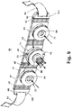
FIG. 9 is an assembled perspective view of the PAPR belt illustrated inFIG. 8 and illustrating an air flow path. -
FIG. 10 is a perspective view of a PAPR belt according to another embodiment of the invention. -
FIG. 11 is a perspective view of a PAPR belt ofFIG. 10 and illustrating a backpack mounted user configuration. -
FIG. 12 is a perspective view of a PAPR belt illustrating a hose management feature. - Referring to
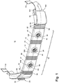
FIGS. 1-3 , a first example of a powered air purifyingrespirator belt 10 useful for understanding the present invention is illustrated. The PAPRbelt 10 generally comprises abelt body 12, aspine 60, amotor 14 and a drivenfan 16 encased within ablower housing 24, and apower source 20 encased in abattery housing 26. Theblower housing 24 andbattery housing 26 are attached to opposite ends of theflexible belt body 12. The PAPRbelt 10 has at least one inlet opening 28 that can be attached to an air filtering means, and anoutlet 30 that can be attached to a user- wearable respiration protection device. The PAPRbelt 10 comprises threeinlet openings 28. The PAPRbelt 10 forms a portion of a belt or bandolier to be worn around the user's waist, back, or other location, and at least thebelt body 12 can be made of a flexible rubber material, such as a Butyl and Silicone blend, or any other suitable material to allow thePAPR belt 10 to conform to the user's body. - The
PAPR belt body 12 is hollow, and can have any cross-sectional configuration, but is preferably rectangular. Thebelt body 12 is comprised of acenter segment 34, abattery end 38, and ablower end 36. Thecenter segment 34 has a plurality of relativelyflat sections 41 bounded bycorrugated sections 42. Thecorrugated sections 42 provide longitudinal as well as lateral flexibility to the belt body so that it can be compressed longitudinally slightly and can bend laterally for conforming to the body of a user. Disposed in each of the threeflat sections 41 is an opening in which afilter mount 106 is installed. Thefilter mount 106 includes an internally threadedfilter sleeve 40 that defines the inlet opening 28 of thePAPR belt 10 and that can be used to couple an air filtering canister or other suitable filter to thePAPR belt 10. Thebelt body 12 acts as an air flow plenum that fluidly communicates theair inlet openings 28 with theair outlet 30. - The
blower housing 24 comprises a blower housingopen end 44, theoutlet 30, and a pair of spaced integral attachingflanges 102 forming a belt recess in the closed end. Theoutlet 30 is defined by an externally threadedhose sleeve 54, which is advantageously used to couple thePAPR belt 10 to a mask facepiece or hood (not shown) via ahose 56. Two attachingflanges 94, each with apin hole 98, are integrally formed in the blower housingopen end 44 and the two attachingflanges 102, each with apin hole 48, are formed in the closed end. Theblower housing 24 can be removably attached to thebelt body 12 at the blower housingopen end 44 through thepin 100 and is sealed in air-tight fashion to theblower end 36 of thebelt body 12. Theblower housing 24 can be made of the same material as thebelt body 12, or any other suitable material. ends of theflexible belt body 12. ThePAPR belt 10 has at least oneinlet 28 that can be attached to an air filtering means, and anoutlet 30 that can be attached to a user-wearable respiration protection device. In the illustrated embodiment, thePAPR belt 10 comprises threeinlets 28. ThePAPR belt 10 forms a portion of a belt or bandolier to be worn around the user's waist, back, or other location, and at least thebelt body 12 can be made of a flexible rubber material, such as a Butyl and Silicone blend, or any other suitable material to allow thePAPR belt 10 to conform to the user's body. - The
PAPR belt body 12 is hollow, and can have any cross-sectional configuration, but is preferably rectangular. Thebelt body 12 is comprised of acenter segment 34, abattery end 38, and ablower end 36. Thecenter segment 34 has a plurality of relativelyflat sections 41 bounded bycorrugated sections 42. Thecorrugated sections 42 provide longitudinal as well as lateral flexibility to the belt body so that it can be compressed longitudinally slightly and can bend laterally for conforming to the body of a user. Disposed in each of the threeflat sections 41 is an opening in which afilter mount 106 is installed. Thefilter mount 106 includes an internally threadedfilter sleeve 40 that defines theinlet 28 of thePAPR belt 10 and that can be used to couple an air filtering canister or other suitable filter to thePAPR belt 10. Thebelt body 12 acts as an air flow plenum that fluidly communicates theair inlets 28 with theair outlet 30. - The
blower housing 24 comprises a blower housingopen end 44, theoutlet 30, and a pair of spaced integral attachingflanges 102 forming a belt recess in the closed end. Theoutlet 30 is defined by an externally threadedhose sleeve 54, which is advantageously used to couple thePAPR belt 10 to a mask facepiece or hood (not shown) via ahose 56. Two attachingflanges 94, each with apin hole 98, are integrally formed in the blower housingopen end 44 and the two attachingflanges 102, each with apin hole 48, are formed in the closed end. Theblower housing 24 can be removably attached to thebelt body 12 at the blower housingopen end 44 through thepin 100 and is sealed in air-tight fashion to theblower end 36 of thebelt body 12. Theblower housing 24 can be made of the same material as thebelt body 12, or any other suitable material. - The
battery housing 26 encases thepower source 20 and comprises a battery housingopen end 46 and a pair of integral attachingflanges 102, each with apin hole 48, in the closed end. Two attachingflanges 94, each with apin hole 98, are integrally formed in the battery housingopen end 46 and the two attachingflanges 102, each with apin hole 48, are formed in the closed end (FIG. 5 ). Thebattery housing 26 can be removably attached to the opposite end of thebelt body 12 through thepin 100. At the battery housingopen end 46, thebattery housing 26 is sealed in air-tight fashion to thebattery end 38 of thebelt body 12. Thebattery housing 26 can be made of the same material as thebelt body 12, or any other suitable material. - Both the
blower housing 24 and thebattery housing 26 have a pair of pin holes 98 located in the opposing short walls, or width, of the open ends 44, 46. The pin holes 98 are utilized in pairs and are spaced from and co-axial with each other. The pin holes 98 retain apin 100, which is positioned between theholes 98. Thepins 100 are utilized to removably retain the ends of aspine 60, to be described below, to theblower housing 24 andbattery housing 26. - The pin holes 48 are utilized in pairs and are spaced from and co-axial with each other. The purpose of the pin holes 48 is to retain a
pin 50, which is positioned between theholes 48. Eachpin 50 provides a structure in the belt recess for which to attach abelt strap 64, to be described below. - A
band 82 is located over the joint where theblower housing 24 andbelt body 12 meet. Asecond band 82 is located over the joint where thebattery housing 26 andbelt body 12 meet. Thebands 82 are positioned on the outer surface of thebelt body 12 and compress the flexible rubber of thebelt body 12 against thehousings bands 82 can be made of any suitable material and preferably can be slid over the joint once thehousings band 82 can be a conventional type of band clamp. - Together, the
belt body 12,battery housing 26, andblower housing 24 form an enclosed space to create a sealedbreathing zone 32 that is in fluid communication with theinlet 28 and theoutlet 30. Thus, only air which has passed through an air filter canister attached to theinlet 28 can pass to a respirator through theoutlet 30. - Referring to
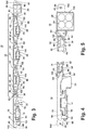
FIG. 4 , enclosed in theblower housing 24 is aninner housing 88, which encases themotor 14 andcentrifugal fan 16. Theinner housing 88 is comprised of two halves, an inner housing upper 90 and an inner housing lower 92, which are fixed together by any suitable means. Thecentrifugal fan 16 andmotor 14 are co-axial and preferably thecentrifugal fan 16 is driven by direct connection via a press fit to an outerrotor brushless motor 14. Theinner housing 88 encircles thecentrifugal fan 16 andmotor 14 and is located between thefan 16 and theblower housing 24. Thecentrifugal fan 16 draws air from theinlet 28, through thebelt body 12, into theblower housing 24, down into theinner housing 88, and propels it radially. Theinner housing 88 then directs the pressurized air toward theoutlet 30. - Referring to
FIG. 5 , enclosed within thebattery housing 26 is acontroller 104 and thepower source 20, which is typically comprised of one ormore batteries 20, preferably rechargeable batteries. Thebattery housing 26 is removable to allow the user to replace or recharge thebatteries 20 upon their discharge. The power source can optionally be a removable battery pack that fits within thebattery housing 26. Dependent on the chosenbatteries 20 or battery pack, thepower source 20 can be configured to provide power to themotor 14 for up to twelve hours of continuous run time. - The
battery housing 26 also includes an integral power switch 86 (FIG. 2 ), which is located on the exterior of thebattery housing 26. Thepower switch 86 is toggled between open and closed positions to control the power supplied by thebatteries 20 to themotor 14. Thebattery housing 26 is only one contemplated location for thepower switch 86; other locations are possible, including remote locations. - The
controller 104 is located within thebattery housing 26 and monitors the speed of the centrifugal fan 16 (FIG. 4 ) and controls the motor 14 (FIG. 4 ) speed in response to the monitoredfan 16 speed to ensure a substantially constant flow rate through thePAPR belt 10. Control of themotor 14 by this method maintains a minimum flow rate between the inlet 28 (FIG. 1 ) and outlet 30 (FIG. 1 ) openings, even when an air filter in line with theinlet 28 is partially clogged. Thecontroller 104 is connected to a speed sensor (not shown) that senses the rotational speed of themotor 14, compares the sensed speed to a predetermined speed set in thecontroller 104 and adjusts the power to themotor 14 so that the sensed speed matches the predetermined. To this end, thecontroller 104 has a power supply circuit that is connected to thebatteries 20 and is also connected to themotor 14 through acable 52 to control the current supplied to themotor 14. Thepower switch 86 toggles between open and closed positions to control the power supplied by thebatteries 20 to thecontroller 104. - Referring now to
FIG. 2 , thepower source 20 provides power to the motor 14 (FIG. 4 ) via thecable 52. Thecable 52 electrically connects thepower source 20 andmotor 14, and extends through the hollow interior of thebelt body 12 from thebattery housing 26 to theblower housing 24. Alternatively, thecable 52 can be molded into the material of thebelt body 12. - Referring to
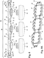
FIGS. 6 and 6A , thespine 60 is located interior to, and along the length of, thebelt body 12. Thespine 60 is made of a somewhat rigid material, preferably a plastic or metal, and has a planar configuration with a number of spacedfingers 62 that protrude outwardly from the surface of thespine 60 with upturned and downturned ends and in registry with theflat portions 41 or thebelt body 12. The spine also has a number of steppedbands 63 that are in registry with thecorrugations 42. Thespine 60 also has a pair ofhooks 96 formed into each end, by which thespine 60 is linked to theblower housing 24 andbattery housing 26. Thehooks 60 are fastened over thepins 100 in the blower housingopen end 44 and battery housingopen end 46. Thespine 60 is slightly shorter that the length of thebelt body 12 so that the belt body must be compressed longitudinally slightly to fasten thehooks 60 over thepins 100, thereby compressing the blower housingopen end 44 and the battery housingopen end 46 tightly against the open ends of thebelt body 12 and thereby seal the blower housingopen end 44 and the battery housingopen end 46 to the open ends of thebelt body 12. Thecorrugations 42 are longitudinally compressed slightly during this fastening process. Thespine 60 extends generally along the inside rear wall of thebelt body 12 and is bent forwardly toward the front wall into thefingers 62 and into the steppedbands 63 at thecorrugations 42 to prevent transverse compression of thebelt body 12. Yet thespine 60 is resilient enough to bend concavely toward the top of the page when thebelt body 12 is bent in one direction around the waist of the user while, due to the geometry of the spline, limits bending in the opposite direction. This spine reduces the possibility of accidental transverse collapse of thebelt body 12 at thecorrugations 42 and at theflat sections 41 if, for example, a user leans up against a wall or the belt is bent too severely. Thespine 60 is configured to prevent complete transverse collapse of thebelt body 12 and thus prevent restriction of airflow through thebelt body 12 due to transverse pressure on a segment of theflexible belt body 12. In addition, thespine 60 also prevents longitudinal stretching of theflexible belt body 12 after installation of theblower housing 24 and thebattery housing 26. - Referring again to
FIG. 1 , thePAPR belt 10 is retained on the user's waist, or other body location, by means of two attached belt straps 64. The belt straps 64 are attached to thepins 50, located in the belt recesses of thebattery housing 26 andblower housing 24. The free ends of the belt straps 64 can be connected together by means of a conventional snap, buckle, or any other suitable attachment method. - Referring to
FIG. 6 , thePAPR belt 10center segment 34 has at least onefilter mount 106 installed in the opening (not shown) in thebelt body 12. Thefilter mount 106 is cylindrical with a threaded interior surface that defines the threadedfilter sleeve 40. Thefilter mount 106 is retained to thebelt body 12 by means of a circular clamping ring 110, which snaps to thefilter mount 106 and compresses thebelt body 12 between thefilter mount 106 and the clamping ring 110. Filter mounts of this type can be found on Avon Protection Systems' respirator masks. - The
PAPR belt 10 can be coupled to an air filtering means, such as acanister filter 22. The attachment is made by threading the externally threadedcanister filter 22 to the internally threadedfilter sleeve 40 of thefilter mount 106 at theinlet 28 of thePAPR belt 10. Thecanister filter 22 typically will include filtration beds for filtering particulate material and/or gaseous material and can be selected comprising various filtering materials according to the user's intended environment. Suitable filter beds are disclosed in theU.S. Patent No. 7,213,595 , which is incorporated herein by reference. ThePAPR belt 10 can be selectively configured to couple with both traditional and conformal canister filters, one type of which is disclosed in U.S. Patent Application Publication No.US 2005/0161911, filed April 26, 2002 . ThePAPR belt 10 can be configured to couple with a filter canister having a standard 40 mm thread, or other standard threads. - In
FIG. 7 , thePAPR belt 10 is shown coupled to an air filter(s) and worn on the waist of a user for use with anair hose 56 between thePAPR belt 10 and amask facepiece 58; however, thePAPR belt 10 can also be worn across the back or chest as a bandolier, or any other body location of a user. ThePAPR belt 10 can be used in combination with aconventional swivel hose 56 that rotates near the connection to theoutlet 30. This pivotal mounting of thehose 56 mounts the hose for rotational movement with respect to thePAPR belt 10 so that thehose 56 can be positioned in a variety of positions, dependent on how thePAPR belt 10 is being worn. Asingle PAPR belt 10 can be used by both right-handed and left-handed users. Thebattery housing 26 andpower switch 86 can be located on the right side of the user's back, as shown inFIG. 7 , for right-handed use, or rotated 180° for left-handed use, locating thebattery housing 26 andpower switch 86 on the left side of the user's back. Thehose 56 is rotated 180 ° about its swivel mounting when inverting thePAPR belt 10 to change from right-handed to left-handed operation. In a similar fashion, thePAPR belt 10 can be worn in various positions across the user's torso, from shoulder to hip in a bandolier style. ThePAPR belt 10 can also advantageously be attached to an SCBA tank (not shown). Further, thePAPR belt 10 can be located remotely from the user's body and used via thehose 56. - Referring to
FIG. 3 , an air flow path of thePAPR belt 10 is illustrated. As described above, power to thePAPR belt 10 can be turned on and off by means of the power switch 86 (FIG. 1 ). When powered on, thePAPR belt 10 draws ambient air through an attachedair filter 22 and into theinlet 28 of thebelt body 12 by thecentrifugal fan 16. Thecentrifugal fan 16 pulls the filtered air into theblower housing 24, down into theinner housing 88, and then propels it radially. Theinner housing 88 directs the pressurized air toward theoutlet 30 of thePAPR belt 10 and to the user wearable respiration protection device. - Referring to
FIG. 8 , an embodiment of thePAPR belt 10 according to the invention is illustrated, where similar elements from the first example are labeled with the same reference numerals. In this embodiment, thePAPR belt 10 includes thebelt body 12, thespine 60, twoblank end caps 68, a threadedadapter 78, and is used in conjunction with a self-containedPAPR module 70. The end caps 68 have a set of pin holes 98 (not shown) and a pin 100 (not shown) and can be removably attached to the spine 60 (FIGS. 6, 6A ) in the same fashion as thebattery housing 26 and theblower housing 24 of the first example. Abelt strap 64 is also attached to the pin 50 (not shown), which is retained by a set of pin holes 48 (not shown) located in the belt recess in each of the end caps 68, in the same fashion as thebattery housing 26 and theblower housing 24 of the first example. The belt straps 64 retain thePAPR belt 10 to the user's body in the same fashion as described above. - The self-contained
PAPR module 70 generally comprises a motor, fan, and power source (not shown) all located within a single housing 72. ThePAPR module 70 has a fan inlet 74 (not shown) that is in fluid communication with thebelt body 12 through the threadedadapter 78 and anoutlet 76 that is in fluid communication with the mask facepiece 58 (Fig. 7 ) through ahose 56. Attachment of thePAPR module 70 to thebelt body 12 can be made by threading the externally threadedadapter 78 to the internally threadedfan inlet 74 of thePAPR module 70 and threading the opposite end of theadapter 78 to the internally threadedfilter sleeve 40 atbelt body 12inlet opening 28. The internally threadedhose 56 is attached to the externally threadedsleeve 80 at thePAPR module 70outlet 76 and the other end extends to a user'smask facepiece 58 or hood. At least onefilter canister 22 having afilter inlet 84 can be attached to thebelt body 12 by threading the externally threadedfilter canister 22 to an internally threadedfilter sleeve 40 at the inlet opening 28 of thebelt body 12, as described above. A full description of thePAPR module 70 is disclosed inWO 2009/067583 . - Referring to
FIG. 9 , in use, unfiltered ambient air is drawn by the centrifugal fan (not shown) of thePAPR module 70 through theinlets 84 of the canister filters 22 and into thebelt body 12. The filtered air passes through thebelt body 12 and into thePAPR module 70. Within thePAPR module 70, the centrifugal fan propels the air radially, a scroll (not shown) spirally directs the pressurized air toward theoutlet 76, and finally the air is passed through thePAPR module 70 to thehose 56 and on to the user's mask facepiece 58 (FIG. 7 ) or hood. - Referring to
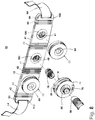
FIG. 10 , another embodiment of thePAPR belt 10 according to the present invention is illustrated, where similar elements from the first example are labeled with the same reference numerals. In this embodiment, thePAPR belt 10 includes thebelt body 12, the spine 60 (FIGS. 6, 6A ), twoend caps 108, a threaded adapter 78 (FIG. 8 ), and is for use in conjunction with a self-containedPAPR module 70 as described above. The end caps 108 can be removably attached to the spine 60 (FIG. 6 ) in the same fashion as thebattery housing 26 and theblower housing 24 of the first example. In this embodiment, no belt straps are provided, and the end caps 108 simply close off the open ends of thebelt body 12. - In
FIG. 11 , thePAPR belt 10 of this embodiment is shown coupled toair filters 22 and worn attached to ahydration pack backpack 112, or any other backpack, to be worn on the back of a user and for use with anair hose 56 between thePAPR belt 10 and amask facepiece 58. Thecombination PAPR belt 10 andhydration pack backpack 112 provides the user with filtered air and hydration. - Referring to
FIG. 12 , another embodiment of thePAPR belt 10 according to the present invention is illustrated, where similar elements from the first example are labeled with the same reference numerals. In this embodiment, thePAPR belt 10 includes a hose management system. The hose management function is provided by hose retention elements, for example, clips 66, located around the periphery of thePAPR belt 10. Theclips 66 can be attached to thebelt body 12 by adhesive, screws, a form of welding, or any other suitable means. Theclips 66 retain thehose 56 on thePAPR belt 10 and provide a compact means of storing thePAPR belt 10. In this fashion, thehose 56 can be retained to thePAPR belt 10 to provide a loop by which to hang up thePAPR belt 10 for decontamination or storage. - The respirator assembly according to the invention can take the form of a kit that includes a variety of modular components, with the
belt body 12 forming the foundational element. The basic components of the respirator kit are thebelt body 12; thespine 60; themotor 14 andfan 16 encased within theblower housing 24; apower source 20 encased in abattery housing 26; and a belt. In addition, the respirator kit can include a variety of filters to suit different conditions, end caps 68, anadaptor 78 and aPAPR module 70. There are many benefits to this respirator, including modular construction for easy configuration, decontamination, and repair. The user can easily clean or decontaminate thePAPR belt 10 by removing the key components, for example, thefilters 22,battery housing 26, andblower housing 24, and submerging theentire center segment 34 of thebelt body 12 in a cleaning solution. Further, because thePAPR belt 10 is made of a flexible rubber, it is also extremely durable and adjustable to fit the individual's body size and movement. It also offers a low profile design for restricted spaces and reduced snagging. - Another significant benefit of this respirator is the modular construction of the
PAPR belt 10, which enables one to mix and match the components as required. With thebattery housing 26 andblower housing 24 in place, any one or more of a variety offilters 22 can be selectively attached to thePAPR belt 10 to protect the user against particular conditions, such as particulate matter, harmful gases, vapors, or CBRN (chemical, biological, radiological, and nuclear) exposure. Alternatively, theblank end caps 68 can be attached to thebelt body 12 and used in conjunction with aPAPR module 70 and filters 22, as selected by the user. ThePAPR belt 10 can also be used by either right-handed or left-handed users. Further, thePAPR belt 10 can also be strapped to a SCBA tank or worn as a bandolier. Convention andconformal filters 22 can be mounted to thePAPR belt 10, and CBRN hazards can be protected against by utilizing CBRN rated filters 22. Thus, the respirator kit provides flexibility for protection in many different adverse conditions. - While the invention has been specifically described in connection with certain specific embodiments thereof, it is to be understood that this is by way of illustration and not of limitation. Reason variation and modification are possible within the scope of the forgoing disclosure and drawings without departing from the invention as defined in the appended claims.
Claims (14)
- An air purifying respirator kit comprising:an elongated hollow belt body (12) having open first and second ends; andat least one filter for supplying purified air to the interior of the belt body (12);characterized in that:the belt body (12) has multiple inlet openings (28) along its length;the at least one filter is a filter canister (22), the at least one filter canister (22) being adapted to be mounted in at least one of the multiple inlet openings (28); andthe air purifying respirator kit further includes:a self-contained powered air purifying respirator (PAPR) module (70) that includes a motor, a fan, a power source, a fan inlet (74) and an outlet (76), wherein the PAPR module (70) is configured to be mounted in one of the multiple inlet openings (28) and wherein, when the at least one filter canister (22) is mounted inone of the multiple openings (28) and the PAPR module (70) is mounted in another one of the multiple openings (28), the fan inlet (74) is in communication withthe at least one filter canister (22) and the outlet (76) is arranged to supply purified air to a user; anda pair of end caps (68, 108) that are attached to the open first and second ends of the belt body to seal the same.
- The air purifying respirator kit of claim 1 and further comprising a hose (56) that is configured to be mounted to the PAPR module outlet (76) for supplying filtered air to a user-wearable respiration protection device (58).
- The air purifying respirator kit of claim 2 wherein the hose (56) has a swivel mounting through which it is configured to be mounted to the PAPR outlet (76), whereby the belt body (12) can be worn in a right orientation or a left orientation by simply inverting the belt body (12) from one orientation to the other.
- The air purifying respirator kit according to claim 2 and further comprising a plurality of hose retention elements that can be mounted to the elongated hollow belt body for releasably mounting a respirator hose (56) to the belt body (12).
- The air purifying respirator kit of claim 1 wherein the power source comprises multiple batteries that are removably mounted to the PAPR module (70).
- The air purifying respirator kit of claim 5 wherein the multiple batteries are rechargeable.
- The air purifying respirator kit of claim 1 wherein the at least one filter canister (22) comprises a variety of filter canisters that with filter media to suit different conditions, including particulate matter, harmful gases, vapors, or CBRN (chemical, biological, radiological, and nuclear) exposure, and that are adapted to mount to the openings (28) in the belt body (12).
- The air purifying respirator kit of claim 1, further comprising a controller that can be electrically connected to the motor for controlling the power to the motor to maintain a constant flow of purified air from a fan outlet.
- The air purifying respirator kit according to claim 1 wherein the elongated hollow belt body (12) is formed of a flexible elastomeric material and is resiliently bendable to conform to a user's body.
- The air purifying respirator kit according to claim 9 wherein the elongated hollow belt body (12) is formed with flat sections (41) that are bounded by corrugated sections (42).
- The air purifying respirator kit according to claim 10 wherein the multiple openings (28) are formed in each flat section.
- The air purifying respirator kit according to claim 11 wherein each of the multiple openings (28) is formed with connectors (106) that are adapted for mounting filter canisters (22).
- The air purifying respirator kit according to claim 1 and further comprising a belt (64) mounted to the end caps (68).
- The air purifying respirator kit according to claim 1 and further comprising a backpack (112) and the elongated hollow belt body (12) is configured to mount to the backpack (112).
Applications Claiming Priority (2)
| Application Number | Priority Date | Filing Date | Title |
|---|---|---|---|
| US5181808P | 2008-05-09 | 2008-05-09 | |
| PCT/US2009/043300 WO2009137770A2 (en) | 2008-05-09 | 2009-05-08 | Integrated belt and plenum powered air purifying respirator |
Publications (3)
| Publication Number | Publication Date |
|---|---|
| EP2274058A2 EP2274058A2 (en) | 2011-01-19 |
| EP2274058A4 EP2274058A4 (en) | 2015-05-06 |
| EP2274058B1 true EP2274058B1 (en) | 2019-04-03 |
Family
ID=41265440
Family Applications (1)
| Application Number | Title | Priority Date | Filing Date |
|---|---|---|---|
| EP09743756.0A Active EP2274058B1 (en) | 2008-05-09 | 2009-05-08 | Integrated belt and plenum powered air purifying respirator |
Country Status (4)
| Country | Link |
|---|---|
| US (2) | US8607784B2 (en) |
| EP (1) | EP2274058B1 (en) |
| CA (1) | CA2723604C (en) |
| WO (1) | WO2009137770A2 (en) |
Families Citing this family (34)
| Publication number | Priority date | Publication date | Assignee | Title |
|---|---|---|---|---|
| ITMN20100014A1 (en) * | 2010-07-02 | 2012-01-03 | Ferrarini Paolo | PORTABLE AIR PURIFICATION DEVICE. |
| US10442028B2 (en) | 2011-05-12 | 2019-10-15 | Lincoln Global, Inc. | Welding helmet configuration providing real-time fume exposure warning capability |
| US9750295B2 (en) | 2011-05-12 | 2017-09-05 | Lincoln Global, Inc. | Welding helmet configuration providing real-time fume exposure warning capability |
| US8757154B2 (en) * | 2011-08-09 | 2014-06-24 | Carmen Schuller | Air purifier apparatus |
| US8574331B2 (en) | 2011-10-26 | 2013-11-05 | Elwha Llc | Air-treatment mask systems, and related methods and air-treatment masks |
| US8887719B2 (en) * | 2011-12-15 | 2014-11-18 | 3M Innovative Properties Company | Air filtration device having tuned air distribution system |
| US8899227B2 (en) * | 2011-12-15 | 2014-12-02 | 3M Innovative Properties Company | Air filtration device having subsections lacking fluid communication |
| US10406387B2 (en) * | 2012-02-15 | 2019-09-10 | 3M Innovative Properties Company | Interlock system for a respirator waist belt |
| CA2815230C (en) * | 2012-05-09 | 2018-12-11 | Avon Protection Systems, Inc. | Filter assembly for a respirator |
| DE102012017176B4 (en) * | 2012-08-30 | 2020-07-16 | Dräger Safety AG & Co. KGaA | Blower filter device of a blower filter system and blower filter system |
| GB2508184A (en) * | 2012-11-22 | 2014-05-28 | 3M Innovative Properties Co | Powered exhaust apparatus for respiratory device |
| CN104161374B (en) * | 2014-08-28 | 2016-08-31 | 江苏东方创意文化产业有限公司 | Belt kettle |
| EP3402991B1 (en) * | 2016-02-29 | 2019-10-16 | Honeywell International Inc. | Thin crossflow blower with stator vanes for a powered air respirator |
| US11260251B2 (en) | 2016-06-23 | 2022-03-01 | 3M Innovative Properties Company | Respirator device with light exposure detection |
| US9998804B2 (en) | 2016-06-23 | 2018-06-12 | 3M Innovative Properties Company | Personal protective equipment (PPE) with analytical stream processing for safety event detection |
| US10610708B2 (en) * | 2016-06-23 | 2020-04-07 | 3M Innovative Properties Company | Indicating hazardous exposure in a supplied air respirator system |
| US11023818B2 (en) | 2016-06-23 | 2021-06-01 | 3M Innovative Properties Company | Personal protective equipment system having analytics engine with integrated monitoring, alerting, and predictive safety event avoidance |
| AU2017281902B2 (en) | 2016-06-23 | 2020-04-09 | 3M Innovative Properties Company | Hearing protector with positional and sound monitoring sensors for proactive sound hazard avoidance |
| US9848666B1 (en) | 2016-06-23 | 2017-12-26 | 3M Innovative Properties Company | Retrofit sensor module for a protective head top |
| KR101685901B1 (en) * | 2016-07-15 | 2016-12-13 | 최연옥 | Portable air cleaner |
| US20180021605A1 (en) * | 2016-07-25 | 2018-01-25 | Mark A. Bartkoski | Coal miner personal air filtration system specially adapted for low ceiling mines |
| US10888721B2 (en) * | 2016-07-28 | 2021-01-12 | Design West Technologies, Inc. | Breath responsive powered air purifying respirator |
| CN106823179A (en) * | 2017-02-28 | 2017-06-13 | 上海朗沁投资管理有限公司 | Neck wears formula controller and air cleaning facility |
| US11883693B2 (en) * | 2019-08-20 | 2024-01-30 | D. Wheatley Enterprises, Inc. | Modular, integrated powered air purifying respirator system |
| USD954252S1 (en) | 2019-10-24 | 2022-06-07 | Rpb Safety, Llc | Powered air purifying respirator |
| USD968588S1 (en) | 2019-10-24 | 2022-11-01 | Rpb Safety, Llc | Powered air purifying respirator main body |
| EP3920317A1 (en) * | 2020-06-04 | 2021-12-08 | Honeywell International Inc. | Improved removable battery pack and latch mechanism for securing a removable battery pack |
| USD940650S1 (en) | 2020-06-04 | 2022-01-11 | Honeywell International Inc. | Battery |
| US20220016447A1 (en) * | 2020-07-14 | 2022-01-20 | Jennifer A. Delaney | Powered Air-Purifying Respirator |
| CN111802733B (en) * | 2020-07-24 | 2022-02-15 | 河南亚都实业有限公司 | Protective clothing for clinical medical treatment |
| US11998777B2 (en) * | 2020-07-27 | 2024-06-04 | Auburn University | Serviceable respirator system with configurable components |
| MX2023014328A (en) * | 2021-06-03 | 2023-12-13 | D Wheatley Entpr Inc | Modular, adjustable powered air purifying respirator system. |
| WO2023085947A1 (en) * | 2021-11-12 | 2023-05-19 | Safeback As | A survival device for feeding a steady supply of breathable air into an environment |
| GB2623807A (en) | 2022-10-28 | 2024-05-01 | Jsp Ltd | Powered air purifying respirator |
Citations (1)
| Publication number | Priority date | Publication date | Assignee | Title |
|---|---|---|---|---|
| WO2009067583A2 (en) * | 2007-11-20 | 2009-05-28 | Avon Protection Systems, Inc. | Modular powered air purifying respirator |
Family Cites Families (20)
| Publication number | Priority date | Publication date | Assignee | Title |
|---|---|---|---|---|
| CA1188193A (en) | 1982-04-06 | 1985-06-04 | Hubert G. Dukowski | Portable air filtration device |
| IL87156A (en) * | 1988-07-20 | 1993-05-13 | Eagle | Forced-ventilation filtration unit particularly for respiration device |
| US4899740A (en) * | 1989-01-17 | 1990-02-13 | E. D. Bullard Company | Respirator system for use with a hood or face mask |
| FR2673380B1 (en) | 1991-02-28 | 1993-06-18 | Intertechnique Sa | PERSONAL RESPIRATORY PROTECTION EQUIPMENT. |
| US5181506A (en) * | 1991-05-02 | 1993-01-26 | The United States Of America As Represented By The Secretary Of The Army | Multilayer protective gas mask |
| US5394870A (en) * | 1993-09-03 | 1995-03-07 | Minnesota Mining And Manufacturing Company | Respirator blower unit housing with pommel-like strap support member comprising lower exterior support surface |
| KR200150250Y1 (en) | 1996-12-24 | 1999-07-01 | 김효근 | A portable air filtering and breathing device |
| US6209144B1 (en) * | 2000-01-10 | 2001-04-03 | Eddie R. Carter | Protective garment |
| US6575165B1 (en) * | 2000-08-03 | 2003-06-10 | 3M Innovative Properties Company | Apparatus and method for breathing apparatus component coupling |
| US6526968B1 (en) * | 2000-11-08 | 2003-03-04 | Mallinckrodt Inc. | Utility belt incorporating a gas storage vessel |
| US6513523B1 (en) * | 2000-11-08 | 2003-02-04 | Mallinckrodt Inc. | Wearable belt incorporating gas storage vessel comprising a polymeric container system for pressurized fluids |
| ITMI20010097A1 (en) | 2001-01-19 | 2002-07-19 | Luca Florindo De | INDIVIDUAL PORTABLE AIR PURIFIER |
| US20030192536A1 (en) * | 2002-04-12 | 2003-10-16 | Raymond Odell | Personal containment system with isolated blower |
| US20040182394A1 (en) * | 2003-03-21 | 2004-09-23 | Alvey Jeffrey Arthur | Powered air purifying respirator system and self contained breathing apparatus |
| CA2427443A1 (en) * | 2003-05-02 | 2004-11-02 | Michel Jauvin | Air disinfection system |
| US7819120B2 (en) * | 2003-12-30 | 2010-10-26 | 3M Innovative Properties Company | Respiratory component mounting assembly |
| US7454800B2 (en) | 2003-12-30 | 2008-11-25 | 3M Innovative Properties Company | Anatomically fitted respiratory component belt |
| US7658190B1 (en) | 2004-04-06 | 2010-02-09 | Sti Licensing Corp. | Portable air-purifying system utilizing enclosed filters |
| US20070163588A1 (en) * | 2005-11-08 | 2007-07-19 | Jack Hebrank | Respirators for Delivering Clean Air to an Individual User |
| US7748381B2 (en) * | 2005-12-09 | 2010-07-06 | 3M Innovative Properties Company | Portable blower system |
-
2009
- 2009-05-08 CA CA2723604A patent/CA2723604C/en active Active
- 2009-05-08 US US12/991,294 patent/US8607784B2/en not_active Ceased
- 2009-05-08 WO PCT/US2009/043300 patent/WO2009137770A2/en active Application Filing
- 2009-05-08 US US14/708,231 patent/USRE46888E1/en active Active
- 2009-05-08 EP EP09743756.0A patent/EP2274058B1/en active Active
Patent Citations (1)
| Publication number | Priority date | Publication date | Assignee | Title |
|---|---|---|---|---|
| WO2009067583A2 (en) * | 2007-11-20 | 2009-05-28 | Avon Protection Systems, Inc. | Modular powered air purifying respirator |
Also Published As
| Publication number | Publication date |
|---|---|
| EP2274058A2 (en) | 2011-01-19 |
| US20110056496A1 (en) | 2011-03-10 |
| USRE46888E1 (en) | 2018-06-12 |
| EP2274058A4 (en) | 2015-05-06 |
| CA2723604A1 (en) | 2009-11-12 |
| US8607784B2 (en) | 2013-12-17 |
| WO2009137770A3 (en) | 2010-03-18 |
| CA2723604C (en) | 2017-11-28 |
| WO2009137770A2 (en) | 2009-11-12 |
Similar Documents
| Publication | Publication Date | Title |
|---|---|---|
| EP2274058B1 (en) | Integrated belt and plenum powered air purifying respirator | |
| EP2555849B1 (en) | Air filtration device | |
| CA2706376C (en) | Modular powered air purifying respirator | |
| JP5851487B2 (en) | Helmet-mounted respirator device with double air supply system | |
| CN105413324B (en) | air filter | |
| RU2372120C2 (en) | Portable air purifier with filters, covered by casing | |
| EP2922599B1 (en) | Powered exhaust apparatus for a personal protection respiratory device | |
| EP1871488B1 (en) | Supplied air respirator that has an adjustable length hose | |
| EP0164946A2 (en) | Improvements in and relating to respirators | |
| CA2751207C (en) | Respirator kit and contoured plenum therefor | |
| EP1353728A1 (en) | Modular respirators and a method of conversion thereof | |
| JP2022546312A (en) | Modular integrated motorized filtering respirator system | |
| EP0108560A1 (en) | Powered air supply units for respirators | |
| EP3797837A1 (en) | Powered exhaust apparatus for a personal protection respiratory device | |
| JP2024520604A (en) | Modular Adjustable Powered Air Purifier Respirator System |
Legal Events
| Date | Code | Title | Description |
|---|---|---|---|
| PUAI | Public reference made under article 153(3) epc to a published international application that has entered the european phase |
Free format text: ORIGINAL CODE: 0009012 |
|
| 17P | Request for examination filed |
Effective date: 20101116 |
|
| AK | Designated contracting states |
Kind code of ref document: A2 Designated state(s): AT BE BG CH CY CZ DE DK EE ES FI FR GB GR HR HU IE IS IT LI LT LU LV MC MK MT NL NO PL PT RO SE SI SK TR |
|
| AX | Request for extension of the european patent |
Extension state: AL BA RS |
|
| RIN1 | Information on inventor provided before grant (corrected) |
Inventor name: WILCOX, JAMES Inventor name: TILLEY, GREG A. |
|
| DAX | Request for extension of the european patent (deleted) | ||
| A4 | Supplementary search report drawn up and despatched |
Effective date: 20150408 |
|
| RIC1 | Information provided on ipc code assigned before grant |
Ipc: A62B 7/00 20060101AFI20150331BHEP Ipc: A62B 18/00 20060101ALI20150331BHEP Ipc: A41D 13/11 20060101ALI20150331BHEP Ipc: A62B 7/10 20060101ALI20150331BHEP Ipc: A62B 9/06 20060101ALI20150331BHEP |
|
| STAA | Information on the status of an ep patent application or granted ep patent |
Free format text: STATUS: EXAMINATION IS IN PROGRESS |
|
| 17Q | First examination report despatched |
Effective date: 20170317 |
|
| GRAP | Despatch of communication of intention to grant a patent |
Free format text: ORIGINAL CODE: EPIDOSNIGR1 |
|
| STAA | Information on the status of an ep patent application or granted ep patent |
Free format text: STATUS: GRANT OF PATENT IS INTENDED |
|
| INTG | Intention to grant announced |
Effective date: 20181017 |
|
| GRAS | Grant fee paid |
Free format text: ORIGINAL CODE: EPIDOSNIGR3 |
|
| GRAA | (expected) grant |
Free format text: ORIGINAL CODE: 0009210 |
|
| STAA | Information on the status of an ep patent application or granted ep patent |
Free format text: STATUS: THE PATENT HAS BEEN GRANTED |
|
| AK | Designated contracting states |
Kind code of ref document: B1 Designated state(s): AT BE BG CH CY CZ DE DK EE ES FI FR GB GR HR HU IE IS IT LI LT LU LV MC MK MT NL NO PL PT RO SE SI SK TR |
|
| REG | Reference to a national code |
Ref country code: GB Ref legal event code: FG4D |
|
| REG | Reference to a national code |
Ref country code: CH Ref legal event code: EP Ref country code: AT Ref legal event code: REF Ref document number: 1115009 Country of ref document: AT Kind code of ref document: T Effective date: 20190415 |
|
| REG | Reference to a national code |
Ref country code: DE Ref legal event code: R096 Ref document number: 602009057722 Country of ref document: DE |
|
| REG | Reference to a national code |
Ref country code: IE Ref legal event code: FG4D |
|
| REG | Reference to a national code |
Ref country code: NL Ref legal event code: MP Effective date: 20190403 |
|
| REG | Reference to a national code |
Ref country code: LT Ref legal event code: MG4D |
|
| REG | Reference to a national code |
Ref country code: AT Ref legal event code: MK05 Ref document number: 1115009 Country of ref document: AT Kind code of ref document: T Effective date: 20190403 |
|
| PG25 | Lapsed in a contracting state [announced via postgrant information from national office to epo] |
Ref country code: NL Free format text: LAPSE BECAUSE OF FAILURE TO SUBMIT A TRANSLATION OF THE DESCRIPTION OR TO PAY THE FEE WITHIN THE PRESCRIBED TIME-LIMIT Effective date: 20190403 |
|
| PG25 | Lapsed in a contracting state [announced via postgrant information from national office to epo] |
Ref country code: NO Free format text: LAPSE BECAUSE OF FAILURE TO SUBMIT A TRANSLATION OF THE DESCRIPTION OR TO PAY THE FEE WITHIN THE PRESCRIBED TIME-LIMIT Effective date: 20190703 Ref country code: FI Free format text: LAPSE BECAUSE OF FAILURE TO SUBMIT A TRANSLATION OF THE DESCRIPTION OR TO PAY THE FEE WITHIN THE PRESCRIBED TIME-LIMIT Effective date: 20190403 Ref country code: CZ Free format text: LAPSE BECAUSE OF FAILURE TO SUBMIT A TRANSLATION OF THE DESCRIPTION OR TO PAY THE FEE WITHIN THE PRESCRIBED TIME-LIMIT Effective date: 20190403 Ref country code: SE Free format text: LAPSE BECAUSE OF FAILURE TO SUBMIT A TRANSLATION OF THE DESCRIPTION OR TO PAY THE FEE WITHIN THE PRESCRIBED TIME-LIMIT Effective date: 20190403 Ref country code: PT Free format text: LAPSE BECAUSE OF FAILURE TO SUBMIT A TRANSLATION OF THE DESCRIPTION OR TO PAY THE FEE WITHIN THE PRESCRIBED TIME-LIMIT Effective date: 20190803 Ref country code: ES Free format text: LAPSE BECAUSE OF FAILURE TO SUBMIT A TRANSLATION OF THE DESCRIPTION OR TO PAY THE FEE WITHIN THE PRESCRIBED TIME-LIMIT Effective date: 20190403 Ref country code: LT Free format text: LAPSE BECAUSE OF FAILURE TO SUBMIT A TRANSLATION OF THE DESCRIPTION OR TO PAY THE FEE WITHIN THE PRESCRIBED TIME-LIMIT Effective date: 20190403 Ref country code: HR Free format text: LAPSE BECAUSE OF FAILURE TO SUBMIT A TRANSLATION OF THE DESCRIPTION OR TO PAY THE FEE WITHIN THE PRESCRIBED TIME-LIMIT Effective date: 20190403 |
|
| PG25 | Lapsed in a contracting state [announced via postgrant information from national office to epo] |
Ref country code: PL Free format text: LAPSE BECAUSE OF FAILURE TO SUBMIT A TRANSLATION OF THE DESCRIPTION OR TO PAY THE FEE WITHIN THE PRESCRIBED TIME-LIMIT Effective date: 20190403 Ref country code: GR Free format text: LAPSE BECAUSE OF FAILURE TO SUBMIT A TRANSLATION OF THE DESCRIPTION OR TO PAY THE FEE WITHIN THE PRESCRIBED TIME-LIMIT Effective date: 20190704 Ref country code: LV Free format text: LAPSE BECAUSE OF FAILURE TO SUBMIT A TRANSLATION OF THE DESCRIPTION OR TO PAY THE FEE WITHIN THE PRESCRIBED TIME-LIMIT Effective date: 20190403 Ref country code: BG Free format text: LAPSE BECAUSE OF FAILURE TO SUBMIT A TRANSLATION OF THE DESCRIPTION OR TO PAY THE FEE WITHIN THE PRESCRIBED TIME-LIMIT Effective date: 20190703 |
|
| REG | Reference to a national code |
Ref country code: CH Ref legal event code: PL |
|
| PG25 | Lapsed in a contracting state [announced via postgrant information from national office to epo] |
Ref country code: AT Free format text: LAPSE BECAUSE OF FAILURE TO SUBMIT A TRANSLATION OF THE DESCRIPTION OR TO PAY THE FEE WITHIN THE PRESCRIBED TIME-LIMIT Effective date: 20190403 Ref country code: IS Free format text: LAPSE BECAUSE OF FAILURE TO SUBMIT A TRANSLATION OF THE DESCRIPTION OR TO PAY THE FEE WITHIN THE PRESCRIBED TIME-LIMIT Effective date: 20190803 |
|
| REG | Reference to a national code |
Ref country code: DE Ref legal event code: R097 Ref document number: 602009057722 Country of ref document: DE |
|
| PG25 | Lapsed in a contracting state [announced via postgrant information from national office to epo] |
Ref country code: LI Free format text: LAPSE BECAUSE OF NON-PAYMENT OF DUE FEES Effective date: 20190531 Ref country code: CH Free format text: LAPSE BECAUSE OF NON-PAYMENT OF DUE FEES Effective date: 20190531 Ref country code: RO Free format text: LAPSE BECAUSE OF FAILURE TO SUBMIT A TRANSLATION OF THE DESCRIPTION OR TO PAY THE FEE WITHIN THE PRESCRIBED TIME-LIMIT Effective date: 20190403 Ref country code: DK Free format text: LAPSE BECAUSE OF FAILURE TO SUBMIT A TRANSLATION OF THE DESCRIPTION OR TO PAY THE FEE WITHIN THE PRESCRIBED TIME-LIMIT Effective date: 20190403 Ref country code: EE Free format text: LAPSE BECAUSE OF FAILURE TO SUBMIT A TRANSLATION OF THE DESCRIPTION OR TO PAY THE FEE WITHIN THE PRESCRIBED TIME-LIMIT Effective date: 20190403 Ref country code: MC Free format text: LAPSE BECAUSE OF FAILURE TO SUBMIT A TRANSLATION OF THE DESCRIPTION OR TO PAY THE FEE WITHIN THE PRESCRIBED TIME-LIMIT Effective date: 20190403 Ref country code: SK Free format text: LAPSE BECAUSE OF FAILURE TO SUBMIT A TRANSLATION OF THE DESCRIPTION OR TO PAY THE FEE WITHIN THE PRESCRIBED TIME-LIMIT Effective date: 20190403 |
|
| REG | Reference to a national code |
Ref country code: BE Ref legal event code: MM Effective date: 20190531 |
|
| PLBE | No opposition filed within time limit |
Free format text: ORIGINAL CODE: 0009261 |
|
| STAA | Information on the status of an ep patent application or granted ep patent |
Free format text: STATUS: NO OPPOSITION FILED WITHIN TIME LIMIT |
|
| PG25 | Lapsed in a contracting state [announced via postgrant information from national office to epo] |
Ref country code: LU Free format text: LAPSE BECAUSE OF NON-PAYMENT OF DUE FEES Effective date: 20190508 |
|
| 26N | No opposition filed |
Effective date: 20200106 |
|
| PG25 | Lapsed in a contracting state [announced via postgrant information from national office to epo] |
Ref country code: TR Free format text: LAPSE BECAUSE OF FAILURE TO SUBMIT A TRANSLATION OF THE DESCRIPTION OR TO PAY THE FEE WITHIN THE PRESCRIBED TIME-LIMIT Effective date: 20190403 |
|
| PG25 | Lapsed in a contracting state [announced via postgrant information from national office to epo] |
Ref country code: IE Free format text: LAPSE BECAUSE OF NON-PAYMENT OF DUE FEES Effective date: 20190508 |
|
| PG25 | Lapsed in a contracting state [announced via postgrant information from national office to epo] |
Ref country code: SI Free format text: LAPSE BECAUSE OF FAILURE TO SUBMIT A TRANSLATION OF THE DESCRIPTION OR TO PAY THE FEE WITHIN THE PRESCRIBED TIME-LIMIT Effective date: 20190403 Ref country code: BE Free format text: LAPSE BECAUSE OF NON-PAYMENT OF DUE FEES Effective date: 20190531 |
|
| PG25 | Lapsed in a contracting state [announced via postgrant information from national office to epo] |
Ref country code: CY Free format text: LAPSE BECAUSE OF FAILURE TO SUBMIT A TRANSLATION OF THE DESCRIPTION OR TO PAY THE FEE WITHIN THE PRESCRIBED TIME-LIMIT Effective date: 20190403 |
|
| PG25 | Lapsed in a contracting state [announced via postgrant information from national office to epo] |
Ref country code: HU Free format text: LAPSE BECAUSE OF FAILURE TO SUBMIT A TRANSLATION OF THE DESCRIPTION OR TO PAY THE FEE WITHIN THE PRESCRIBED TIME-LIMIT; INVALID AB INITIO Effective date: 20090508 Ref country code: MT Free format text: LAPSE BECAUSE OF FAILURE TO SUBMIT A TRANSLATION OF THE DESCRIPTION OR TO PAY THE FEE WITHIN THE PRESCRIBED TIME-LIMIT Effective date: 20190403 |
|
| PG25 | Lapsed in a contracting state [announced via postgrant information from national office to epo] |
Ref country code: MK Free format text: LAPSE BECAUSE OF FAILURE TO SUBMIT A TRANSLATION OF THE DESCRIPTION OR TO PAY THE FEE WITHIN THE PRESCRIBED TIME-LIMIT Effective date: 20190403 |
|
| P01 | Opt-out of the competence of the unified patent court (upc) registered |
Effective date: 20230429 |
|
| PGFP | Annual fee paid to national office [announced via postgrant information from national office to epo] |
Ref country code: GB Payment date: 20240426 Year of fee payment: 16 |
|
| PGFP | Annual fee paid to national office [announced via postgrant information from national office to epo] |
Ref country code: DE Payment date: 20240425 Year of fee payment: 16 |
|
| PGFP | Annual fee paid to national office [announced via postgrant information from national office to epo] |
Ref country code: FR Payment date: 20240425 Year of fee payment: 16 |
|
| PGFP | Annual fee paid to national office [announced via postgrant information from national office to epo] |
Ref country code: IT Payment date: 20240523 Year of fee payment: 16 |