EP2274047B1 - Electrical wound healing system - Google Patents
Electrical wound healing system Download PDFInfo
- Publication number
- EP2274047B1 EP2274047B1 EP09703844.2A EP09703844A EP2274047B1 EP 2274047 B1 EP2274047 B1 EP 2274047B1 EP 09703844 A EP09703844 A EP 09703844A EP 2274047 B1 EP2274047 B1 EP 2274047B1
- Authority
- EP
- European Patent Office
- Prior art keywords
- wound
- electrodes
- composite
- electrode
- array
- Prior art date
- Legal status (The legal status is an assumption and is not a legal conclusion. Google has not performed a legal analysis and makes no representation as to the accuracy of the status listed.)
- Active
Links
- 230000029663 wound healing Effects 0.000 title claims description 27
- 206010052428 Wound Diseases 0.000 claims description 154
- 208000027418 Wounds and injury Diseases 0.000 claims description 154
- 239000002131 composite material Substances 0.000 claims description 115
- 239000000203 mixture Substances 0.000 claims description 11
- 230000004044 response Effects 0.000 claims description 2
- 210000001519 tissue Anatomy 0.000 description 24
- 238000012544 monitoring process Methods 0.000 description 12
- 230000001225 therapeutic effect Effects 0.000 description 12
- 238000004891 communication Methods 0.000 description 10
- 230000035876 healing Effects 0.000 description 9
- 230000000638 stimulation Effects 0.000 description 9
- 230000005684 electric field Effects 0.000 description 8
- 239000000499 gel Substances 0.000 description 6
- 238000000034 method Methods 0.000 description 6
- 230000035515 penetration Effects 0.000 description 5
- 239000000758 substrate Substances 0.000 description 5
- 230000008901 benefit Effects 0.000 description 4
- 238000013507 mapping Methods 0.000 description 4
- 239000007787 solid Substances 0.000 description 4
- 230000008859 change Effects 0.000 description 3
- 238000010586 diagram Methods 0.000 description 3
- 238000012360 testing method Methods 0.000 description 3
- 238000013459 approach Methods 0.000 description 2
- 230000009286 beneficial effect Effects 0.000 description 2
- 239000004020 conductor Substances 0.000 description 2
- 230000000694 effects Effects 0.000 description 2
- 230000036074 healthy skin Effects 0.000 description 2
- 238000002847 impedance measurement Methods 0.000 description 2
- 238000005259 measurement Methods 0.000 description 2
- 238000007650 screen-printing Methods 0.000 description 2
- 206010067484 Adverse reaction Diseases 0.000 description 1
- 208000010392 Bone Fractures Diseases 0.000 description 1
- 239000012790 adhesive layer Substances 0.000 description 1
- 230000006838 adverse reaction Effects 0.000 description 1
- 238000004458 analytical method Methods 0.000 description 1
- 230000001580 bacterial effect Effects 0.000 description 1
- 230000015572 biosynthetic process Effects 0.000 description 1
- 230000007423 decrease Effects 0.000 description 1
- 239000012777 electrically insulating material Substances 0.000 description 1
- 238000001827 electrotherapy Methods 0.000 description 1
- 230000002708 enhancing effect Effects 0.000 description 1
- 239000000017 hydrogel Substances 0.000 description 1
- 239000000976 ink Substances 0.000 description 1
- 238000007689 inspection Methods 0.000 description 1
- 238000011835 investigation Methods 0.000 description 1
- 230000001788 irregular Effects 0.000 description 1
- 239000010410 layer Substances 0.000 description 1
- 239000000463 material Substances 0.000 description 1
- 230000007433 nerve pathway Effects 0.000 description 1
- 210000000944 nerve tissue Anatomy 0.000 description 1
- 229920000728 polyester Polymers 0.000 description 1
- 238000012545 processing Methods 0.000 description 1
- 238000012552 review Methods 0.000 description 1
- 210000004872 soft tissue Anatomy 0.000 description 1
- 230000008685 targeting Effects 0.000 description 1
Images


Classifications
-
- A—HUMAN NECESSITIES
- A61—MEDICAL OR VETERINARY SCIENCE; HYGIENE
- A61N—ELECTROTHERAPY; MAGNETOTHERAPY; RADIATION THERAPY; ULTRASOUND THERAPY
- A61N1/00—Electrotherapy; Circuits therefor
- A61N1/02—Details
- A61N1/04—Electrodes
- A61N1/0404—Electrodes for external use
- A61N1/0408—Use-related aspects
- A61N1/0468—Specially adapted for promoting wound healing
-
- A—HUMAN NECESSITIES
- A61—MEDICAL OR VETERINARY SCIENCE; HYGIENE
- A61B—DIAGNOSIS; SURGERY; IDENTIFICATION
- A61B5/00—Measuring for diagnostic purposes; Identification of persons
- A61B5/44—Detecting, measuring or recording for evaluating the integumentary system, e.g. skin, hair or nails
- A61B5/441—Skin evaluation, e.g. for skin disorder diagnosis
- A61B5/445—Evaluating skin irritation or skin trauma, e.g. rash, eczema, wound, bed sore
-
- A—HUMAN NECESSITIES
- A61—MEDICAL OR VETERINARY SCIENCE; HYGIENE
- A61N—ELECTROTHERAPY; MAGNETOTHERAPY; RADIATION THERAPY; ULTRASOUND THERAPY
- A61N1/00—Electrotherapy; Circuits therefor
- A61N1/02—Details
- A61N1/04—Electrodes
- A61N1/0404—Electrodes for external use
- A61N1/0472—Structure-related aspects
- A61N1/0476—Array electrodes (including any electrode arrangement with more than one electrode for at least one of the polarities)
-
- A—HUMAN NECESSITIES
- A61—MEDICAL OR VETERINARY SCIENCE; HYGIENE
- A61N—ELECTROTHERAPY; MAGNETOTHERAPY; RADIATION THERAPY; ULTRASOUND THERAPY
- A61N1/00—Electrotherapy; Circuits therefor
- A61N1/02—Details
- A61N1/04—Electrodes
- A61N1/0404—Electrodes for external use
- A61N1/0472—Structure-related aspects
- A61N1/0492—Patch electrodes
-
- A—HUMAN NECESSITIES
- A61—MEDICAL OR VETERINARY SCIENCE; HYGIENE
- A61N—ELECTROTHERAPY; MAGNETOTHERAPY; RADIATION THERAPY; ULTRASOUND THERAPY
- A61N1/00—Electrotherapy; Circuits therefor
- A61N1/18—Applying electric currents by contact electrodes
- A61N1/20—Applying electric currents by contact electrodes continuous direct currents
- A61N1/205—Applying electric currents by contact electrodes continuous direct currents for promoting a biological process
-
- A—HUMAN NECESSITIES
- A61—MEDICAL OR VETERINARY SCIENCE; HYGIENE
- A61B—DIAGNOSIS; SURGERY; IDENTIFICATION
- A61B5/00—Measuring for diagnostic purposes; Identification of persons
- A61B5/05—Detecting, measuring or recording for diagnosis by means of electric currents or magnetic fields; Measuring using microwaves or radio waves
- A61B5/053—Measuring electrical impedance or conductance of a portion of the body
- A61B5/0531—Measuring skin impedance
-
- A—HUMAN NECESSITIES
- A61—MEDICAL OR VETERINARY SCIENCE; HYGIENE
- A61B—DIAGNOSIS; SURGERY; IDENTIFICATION
- A61B5/00—Measuring for diagnostic purposes; Identification of persons
- A61B5/44—Detecting, measuring or recording for evaluating the integumentary system, e.g. skin, hair or nails
- A61B5/441—Skin evaluation, e.g. for skin disorder diagnosis
-
- A—HUMAN NECESSITIES
- A61—MEDICAL OR VETERINARY SCIENCE; HYGIENE
- A61N—ELECTROTHERAPY; MAGNETOTHERAPY; RADIATION THERAPY; ULTRASOUND THERAPY
- A61N1/00—Electrotherapy; Circuits therefor
- A61N1/02—Details
- A61N1/04—Electrodes
- A61N1/0404—Electrodes for external use
- A61N1/0408—Use-related aspects
- A61N1/0428—Specially adapted for iontophoresis, e.g. AC, DC or including drug reservoirs
-
- A—HUMAN NECESSITIES
- A61—MEDICAL OR VETERINARY SCIENCE; HYGIENE
- A61N—ELECTROTHERAPY; MAGNETOTHERAPY; RADIATION THERAPY; ULTRASOUND THERAPY
- A61N1/00—Electrotherapy; Circuits therefor
- A61N1/18—Applying electric currents by contact electrodes
- A61N1/32—Applying electric currents by contact electrodes alternating or intermittent currents
- A61N1/326—Applying electric currents by contact electrodes alternating or intermittent currents for promoting growth of cells, e.g. bone cells
Definitions
- the preferred creating means creates said composite electrodes by electrically connecting together the, or each, electrode of the array that is to form part of the respective composite electrode.
- the creating means may include a switching device arranged to selectably connect (at least electrically) each array electrode to one or other of a positive and a negative terminal by which said electrical signal is applied in use to the composite electrodes.
- the system 10 is arranged to perform the wound monitoring technique described in WO 2004/049937 , or a similar method of monitoring a wound.
- the system 10 is operable in a second mode of operation in which it measures one or more electrical characteristics of the wound, e.g. impedance, in order to provide a map of the wound.
- the array 12 may for example be used in the manner described in WO 2004/049937 .
- the controller 26 configures some or all of the electrodes 14, 22, 33 (as applicable), the switch device 24, and the signal generating circuit 27, to implement any one of the wound mapping methods disclosed by WO2004/049937 .
- the combinations of electrodes 14 used can be varied during the healing process in order to direct the therapeutic waveforms/signals to the appropriate areas of the wound. Typically, it is a cathode that is placed over the wound and an anode placed off the wound. In embodiments of the present invention, combinations of electrodes 14 can be electrically grouped together to form the composite anode, and combinations of electrodes 14 can be electrically grouped together to form the composite anode. These combinations can be chosen to best replicate the size and shape of the targeted area(s) of the wound and to produce the desired electrical field in the targeted area(s), including the desired depth of penetration in the target area(s).
- the system 10 performs wound monitoring to assess the state of the wound and so to provide data for use in the first mode of operation.
- the system 10 can optionally be disconnected from the computer 36.
- the controller 26 may be programmed to make some adjustments to the characteristics of the applied electrical signal and/or the composition of the composite electrodes based on the measured impedance values (and/or other measured characteristics) without communicating with the computer 36.
- the computer 36 may perform the role of the controller 26 without the need for a separate microcontroller or other device.
- the computer 36 is arranged for communication with the system 10 by any conventional means, preferably a wireless connection in which case the system 10 and computer 36 are equipped with suitable transceiving devices.
- preferred embodiments of the invention enable the responsive and optimal targeting of wound healing electrotherapy by monitoring the wound's condition and location and using this information to select and modify the size, shape and/or location of composite electrotherapeutic electrodes and, optionally, to also modify the polarity and waveform characteristics of the applied electrotherapeutic signal.
- the shape of the or each composite electrode may be selected to substantially match the determined shape of the wound, especially the perimeter, or part of the perimeter of the wound.
- the size of the or each composite electrode may be selected to substantially match the determined size of the wound, or wound portion, and/or the location of the or each composite electrode may be selected to substantially match the determined location of the wound, or wound portion.
Description
- The present invention relates to electrical wound healing systems.
- It is believed that the rate of wound healing can be enhanced by electrostimulation, i.e. the application of a therapeutic electrical signal, or waveform, to the wound. Conventionally, the electrical signal is applied by two electrodes, one placed on either side of the wound. A problem with this approach is that the electrical signal is applied across the whole of the wound regardless of tissue type or stage of healing. It is also believed that healing is enhanced if the two electrodes are placed one on either side of a wound boundary, the electrodes being shaped to closely follow the contours of the wound. In this way, the two electrodes create an optimal wound- healing electrical field across the wound edge. However, achieving suitably shaped electrodes is not feasible with standard electrode systems.
- It would be desirable to mitigate the problems outlined above.
-
WO 2004/049937 discloses a tissue mapping system comprising a two dimensional array oftest electrodes 10 for application to the surface of tissue under investigation and circuit means 50-66 for measuring an electrical characteristic of the tissue underlying each test electrode. In one embodiment the electrical characteristics is the impedance of the tissue underlying each test electrode. -
US 7 177 696 discloses a method and apparatus for speeding the healing process of soft tissues, bone fractures, cancerous tissue, nerve pathways and other body tissues wherein a portable base comprising a plurality of cells is applied with the cells facing or encircling the wound. - A first aspect of the invention provides a wound healing system according to
claim 1. - The preferred creating means creates said composite electrodes by electrically connecting together the, or each, electrode of the array that is to form part of the respective composite electrode. To this end, the creating means may include a switching device arranged to selectably connect (at least electrically) each array electrode to one or other of a positive and a negative terminal by which said electrical signal is applied in use to the composite electrodes.
- The system typically also comprises a controller arranged to control the setting of said switch device, for example by means of a multiplexer. The controller may also be arranged to cause said electrical signal to be applied to said composite electrodes and, preferably, also to generate said electrical signal (in association with other circuitry if necessary, e.g. a pulse generating circuit, or other signal generating circuit).
- Preferably, the system is arranged to cause a respective one or more electrodes to form the respective first and second composite electrodes depending on a desired shape, size and/or location of the respective composite electrodes.
- The system may include means for selecting said respective one or more electrodes for forming the respective first and second composite electrodes. The selection is advantageously based on information concerning the state of the wound. This information may for example be provided to the system by a user via a user interface, and/or by a wound monitoring system.
- In preferred embodiments, the system includes, or is in communication with, a wound monitoring system. The wound monitoring system may comprise means for measuring one or more electrical characteristics of the wound; and means for analysing the, or each, measured electrical characteristics to determine the state of the wound. Conveniently, the measuring means includes, or at least employs, the electrode array. A suitable wound monitoring system is disclosed in International PCT patent application
WO 2004/049937 . Alternative wound monitoring systems may be employed and do not necessarily need to use the electrode array. - In such embodiments, the system may operate in a first mode of operation, in which said electrical signal is applied to the composite electrodes for the purpose of enhancing wound healing, and a second mode of operation, in which the state of the wound is monitored.
- The controller may be arranged to perform some or all of the processing mentioned above, e.g. the selection of electrodes, the measuring of electrical characteristics and/or the analysing of the measured electrical characteristics. In preferred embodiments, however, the controller is in communication with a computer arranged to perform some or all of these tasks.
- In preferred embodiments, the system is arranged to create one of said composite electrodes from one or more array electrodes that are determined to be located, in use, over one or more wounded portions of the tissue and/or skin underlying the array in use, e.g. portions that are determined to be relatively damaged or unhealthy. Preferably, said one composite electrode is created to substantially fill the, or each, wounded portion.
- Conveniently, the other of said composite electrodes is created from one or more array electrodes that are determined to be located, in use, outside of said one or more wounded portions. Preferably, said other of the composite electrodes is created only from electrodes that are determined to be located at, or substantially at, an edge of the, or each, wounded portion.
- Alternatively, the system is arranged to create one of said composite electrodes from one or more array electrodes that are determined to be located, in use, at one side of one or more wounded portions of the tissue and/or skin underlying the array in use, the other of said composite electrodes being created from one or more array electrodes that are determined to be located, in use, at the opposite side of said one or more wounded portions.
- Preferably, the system is arranged to adjust the electrode composition of said composite electrodes depending on determined changes in the state of the wound.
- The polarity of the applied electrical signal, and/or one or more other characteristics of the applied electrical signal may also be selected and/or changed depending on the determined state of the wound and/or on determined changes in the state of the wound.
- The array typically comprises a two dimensional array electrodes, preferably arranged in a substantially rectangular shape. The array should comprise at least three electrodes, but typically comprises at least twenty five electrodes. In typical embodiments, the electrode array is incorporated into a wound dressing.
- The present invention is particularly concerned with treating and monitoring wounds in a subject's skin, and therefore also in the tissue that forms the skin, not just the outer layer of skin. Accordingly, references herein to skin are intended to embrace also any tissue that may be damaged or exposed when skin is wounded.
- Further advantageous aspects of the invention will become apparent to those ordinarily skilled in the art upon review of the following description of a specific embodiment and with reference to the accompanying drawings.
- An embodiment of the invention is now described by way of example and with reference to the accompanying drawings in which:
-
Figure 1 is a block diagram of a wound healing system embodying one aspect of the invention; -
Figures 2A to 2D are schematic diagrams of an electrode array suitable for use in the system ofFigure 1 , the array of each Figure being shown in a different configuration and superimposed on a wound; and -
Figure 3 is a schematic representation of the effect of inter electrode distance on the depth of penetration of the applied electrical field. - Referring now to
Figure 1 of the drawings, there is shown, generally indicated as 10, a wound healing system embodying one aspect of the invention. The system is particularly concerned with healing wounds formed in the skin of a patient (typically human), the wound area typically comprising one or more portions of relatively damaged or unhealthy tissue and relatively undamaged or intact skin. Thesystem 10 comprises at least one electrode array 12 (only one shown) comprising a plurality ofelectrodes 14. Theelectrodes 14 are arranged in a two dimensional array. In the illustrated embodiment, thearray 12 is a 7 x 7 array, although thearray 12 may alternatively have more orfewer electrodes 14. The illustratedarray 12 is rectangular, or more particularly square, but may take alternative shapes, e.g. substantially circular or polygonal. The distribution of theelectrodes 14 within thearray 12 may be regular or irregular. Theelectrodes 14 themselves are shown as rectangular but may take any suitable shape. - Each
electrode 14 is electrically connected to arespective lead 16, or other suitable signal conductor(s), by which electrical signals may be supplied to or from theelectrode 14 during use. For convenience, theleads 16 are brought together at an edge of thearray 12 and incorporated into aconnector 20 by which electrical signals can be sent to, or received from, thearray 12. InFigure 1 , for clarity the individual leads 16 are not shown connected to eachelectrode 14, although some of them are shown as part of theconnector 20. - Typically, the
electrodes 14 are carried by a substrate 18. This may be achieved by any suitable means, for example screen printing. Theelectrodes 14 and leads 16 may be formed from any suitable electrically conductive material, especially conductive inks that are amenable to screen printing. The substrate 18 may be formed from any suitable material, typically an electrically insulating material, e.g. polyester. The substrate 18 may be comprised of one continuous sheet (as illustrated) or may be provided in strips, each strip carrying one or more electrodes. In either case, theelectrodes 14 in thearray 12 are physically, or spatially, close to one another such that they form part of a common device for applying electrical signals to a localised area, in particular a wound. - By way of example, further details concerning the formation of a suitable electrode array may be found in International
PCT patent application WO 2004/049937 , which discloses a 'smart dressing' system that enables the monitoring of a wound site using a multi-electrode array incorporated into the dressing. The system ofWO 2004/049937 differentiates between intact skin and a wound by measuring, for example, the impedance under each electrode on the array. The resulting data can be used to generate a wound map according to, for example, the relative magnitudes of the measured skin impedances. - Optionally, one or more reference electrodes 22 (only one present in the illustrated embodiment) may be provided. The, or each,
reference electrode 22 is conveniently provided on thearray 12, in any suitable manner, preferably adjacent thearray 12. Thereference electrode 22 may be used to provide a reference signal for impedance measurements as, for example, is described in more detail inWO 2004/049937 . - The
array 12, including the substrate 18 and, when present, the reference electrode(s) may be incorporated into a wound dressing. This may be achieved in any suitable manner, for example as described inWO 2004/049937 . - The
electrodes system 10 via theconnector 20. Any other suitable means for electrical communication between theelectrodes system 10 may be used in which case some or all of theleads 16 may be dispensed with. - The
system 10 includes means for applying an electrical signal to one or more of theelectrodes 14 simultaneously. In one mode of use, the electrical signal comprises a therapeutic signal, for example an iontophoretic signal, or other signal used in the electrostimulation of wounds. The signal is generated by a signal generating apparatus which, in the illustrated embodiment, comprises asignal generating circuit 27 under the control of acontroller 26. In this example, thecontroller 26 conveniently takes the form of a suitably programmed microcontroller, although it may alternatively take other forms. The illustratedsignal generating circuit 27 comprises asignal generator 29, avoltage booster 30, acurrent controller 32, and aDC controller 28. Apower supply 31, e.g. in the form of a battery, is also provided to supply electrical power to the circuit. - The
signal generating circuit 27 is advantageously capable of generating a range of adjustable waveforms (e.g. continuous, pulsed, square wave current/voltage etc.). By way of example, the signal generating circuit may comprise a pulse generating circuit that enables the adjustment of amplitude, frequency and/or duty cycle. It will be understood that thecircuit 27 ofFigure 1 is not limiting and that a variety of alternative signal generating circuits could be used instead. - The signal is provided to a
switching device 24, the setting of which determines to which electrode(s) 14 the signal is supplied. The switchingdevice 24 typically comprises a respective switch (not shown) for eachelectrode 14, the setting of which determines whether therespective electrode 14 is electrically connected to thesignal generator 27 in order to receive the electrical signal, or connected to areturn line 40 in order to complete the circuit, i.e. the setting of the switches in thedevice 24 determines whether therespective electrodes 14 act as an anode or a cathode (although depending on the composition of the composite electrodes, some of theindividual electrodes 14 may not be involved in the circuit). In the present embodiment, the switchingdevice 24 is controlled by thecontroller 26 using ademultiplexer 34 that allows each of the respective switches to be set individually. - In the illustrated embodiment, the
controller 26 is adapted for communication with acomputer 36. Thecomputer 36 is arranged to receive data from the controller 36 (and/or via a user interface (not shown)), to analyse the received data and to determine how to configure theelectrodes 14 in the array 12 (as is described in more detail hereinafter). Thecomputer 36 may also determine the characteristics of the electrical signal to be generated by thesystem 10. Thecomputer 36 then instructs thecontroller 36 to cause thearray 12 to be configured accordingly (by means of the switching device 24) and to cause the selected electrical signal to be sent to thearray 12. In this embodiment, thecomputer 36 andcontroller 26 together provide means for controlling thesystem 10 and, in particular, means for determining how theelectrodes 14 in thearray 12 are configured. To this end, thecomputer 36 supports appropriate computer software. - In the preferred embodiment, the
computer 36 is programmed to determine, for example from data received from thearray 12, the state of the tissue beneath the array 12 (e.g. which portions are damaged, which are intact and relative states in between). This allows thecomputer 36 to determine how to configure thearray 12. By way of example, this may be achieved by a method the same or similar to that disclosed inWO 2004/049937 , i.e. by differentiating between intact skin and a wound by measuring, for example, the impedance (or other electrical characteristic) under each electrode of the array. To this end, thesystem 10 may include an impedance analyser (not shown) the same or similar to the impedance analyser disclosed inWO 2004/049937 . The impedance analyser may take the form of computer software supported by thecomputer 36, or may be a separate unit (not illustrated) in communication with thecomputer 36. It will be understood that alternative means for controlling thesystem 10 other than thecomputer 36 andcontroller 26 may be used. For the purposes of impedance measurement, thesystem 10 may also include aback electrode 33, which may be arranged and used as described inWO 2004/049937 . - Communication between the
controller 26 and the rest of thesystem 10 may be implemented by any convenient means and is indicated by broken lines inFigure 1 . In the illustrated embodiment, thecontroller 26 is in communication with theDC control 28 to control thecircuitry 27, and with the switchingdevice 24 to receive signals from therelevant electrodes 14 depending on the setting of the switches. - In one mode of use, the
electrodes 14 are arranged into one or more groups, each group comprising one ormore electrode 14. Theelectrodes 14 in each group are electrically connected together, or at least arranged to carry a common electrical signal. Hence, each electrode group acts as a respective single electrode and may be referred to as a composite electrode. Electrostimulation signals may then be applied via the composite electrode(s). Typically, first and second composite electrodes are defined. In typical modes of use, d.c. signals are applied to the wound and so one of the composite electrodes may be designated as the anode, and the other may be designated as the cathode. In alternative embodiments, the electrical signals applied to the wound may comprise pulses or a.c. signals. - For example, in a mode of use where the "wound" composite electrode (i.e. a composite electrode positioned in use over a wounded area of tissue and/or skin) is designated as the negative electrode, the
system 10 is arranged to simultaneously supply a common electrical signal to all of theelectrodes 14 in the composite cathode (positive composite electrode), the composite anode providing a signal return path to thesystem 10. In the illustrated embodiment, the electrical grouping, or connection, of theelectrodes 14 is achieved by the switchingdevice 24. For example, the respective switch for eachelectrode 14 forming part of the composite cathode is set to connect itsrespective electrode 14 to thesignal generator 27, while the respective switch for eachelectrode 14 forming part of the anode is set to connect itsrespective electrode 14 to thereturn line 40. - In the preferred embodiment, one of the composite electrodes is arranged for positioning, in use, over healthy or relatively healthy skin and/or tissue and is referred to hereinafter as the "healthy electrode". The other composite electrode is arranged for positioning, in use, over damaged, or relatively damaged, skin and/or tissue and is referred to hereinafter as the "wound electrode". Advantageously, the wound electrode is shaped and dimensioned to substantially fill the, or each, portion of wounded tissue beneath the
array 12. The healthy electrode may be shaped and dimensioned to substantially surround the, or each, portion of wounded tissue. The shape and dimensions of the composite electrodes are determined by the electrode(s) 14 of which they are composed. The typical arrangement is such that the composite anode is the healthy electrode, while the composite cathode is the wound electrode, although the reverse arrangement is possible. - During use, the electrode composition of the composite electrodes may be changed by the
system 10. In particular, thecomputer 36 determines which electrode(s) 14 are to form part of the respective composite electrodes and instructs thecontroller 26 to cause thearray 12 to be configured accordingly. For example, one or more of the respective electrode(s) 14 that make up one or both of the composite electrodes may be changed, and/or the polarity of the composite electrodes may be changed. Advantageously, changing the composition of the composite electrodes is performed in response to detected changes in the state of the wound. For example, as the wound heals, the portions of tissue that are regarded as damaged or healthy may change and so it may be desired to change the shape, size and/or position of the healthy and/or wound electrodes. - In the preferred embodiment, the
system 10 is arranged to perform the wound monitoring technique described inWO 2004/049937 , or a similar method of monitoring a wound. To this end, thesystem 10 is operable in a second mode of operation in which it measures one or more electrical characteristics of the wound, e.g. impedance, in order to provide a map of the wound. In the second mode of operation, thearray 12 may for example be used in the manner described inWO 2004/049937 . For example, in conjunction with thecomputer 36, thecontroller 26 configures some or all of theelectrodes switch device 24, and thesignal generating circuit 27, to implement any one of the wound mapping methods disclosed byWO2004/049937 . Hence, thecomputer 36 is able to determine the state of the wound from the data provided to it by thearray 12. This allows thecomputer 36 to determine which portions of the tissue under thearray 12 are to be regarded as healthy and which are to be regarded as damaged. This in turn allows thecomputer 36 to select a corresponding composition for the respective composite electrodes in the first mode of operation. The selection of the composition of the composite electrodes may be achieved by any other method, for example manual selection by a user. - It will be seen therefore that it is possible to use the
electrode array 12 in a wound mapping mode to locate the wound and determine its shape, and then to use this information to group electrically subsets of the array'selectrodes 14 to form an optimally shaped and sized composite wound electrode and healthy electrode. In particular,electrodes 14 that are identified as being located over healthy intact skin are connected together electrically to form a single composite electrode (the healthy electrode).Electrodes 14 that are identified as being located over the wound are connected together electrically and thus form a second composite electrode (the wound electrode). This is the simplest case and assumes that the wound forms a single 'island' surrounded by healthy skin. - Given that the position, shape and size of the wound can be monitored by the wound mapping measurements, a further advantage of this approach is that the composite electrodes can be continuously or intermittently reshaped (manually or automatically by the system 10) as wound healing occurs and the wound area decreases and/or changes shape. This allows optimal targeted delivery of the therapeutic signals, i.e. a 'responsive' electrode system incorporating feedback control is provided.
-
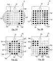
Figure 2A shows an example of howelectrodes 14 in thearray 12 on either side of a wound 50 (indicated in broken outline) can be grouped together electrically to form composite stimulation electrodes. InFigure 2A , theelectrodes 14A (shown hatched) to the left of thewound 50 are grouped electrically to form one composite stimulation electrode, while theelectrodes 14B (shown with solid fill) on the right are grouped electrically to form the other composite stimulation electrode. In this case, the electrical signal is applied, in use, across substantially theentire wound 50. -
Figure 2B shows an example of how the electrodes in thearray 12 may be configured to form a "wound" composite electrode and a "healthy" composite electrode. InFigure 2B , it is assumed that, based on impedance or potential, or related measurements made at theelectrodes 14 in the second mode of operation (or by manual inspection), thewound 50 is determined to be under a group of central electrodes 14C (shown hatched). The electrodes 14C are connected electrically together in the first mode of operation to form the composite "wound" electrode. Theelectrodes 14D (shown with solid fill) located over intact, or relatively healthy, skin in this simplistic example, are also grouped together electrically to form the composite "healthy" electrode. - It is noted that the electrode(s) used to apply the therapeutic electrical signal, or waveform, (denoted 'healthy' electrode in the example above) could be located on any remote skin site on the patient and do not necessarily have to be formed from the
array electrodes 14 located over healthy tissue. More generally, the "healthy" electrode, irrespective of polarity, may be located elsewhere on the patient and need not necessarily be implemented by theelectrodes 14. - It is also noted that it is not necessary to use all of the
electrodes 14 in thearray 12 to form the composite electrodes. For example, only thoseelectrodes 14 that are closest to the wound edge (on either or both sides of the wound edge) may be used to form the composite electrodes. This is illustrated inFigure 2C whereelectrodes 14E (shown hatched) are those located over thewound 50 and are electrically grouped together to form the composite wound electrode. Theelectrodes 14H (shown with no fill) are located over intact skin and do not form part of a composite electrode in this instance. Theelectrodes 14F (shown in solid fill) are located at the edges of thewound 50 on the side of intact tissue. Theelectrodes 14F can be electrically grouped together to form a composite 'healthy' electrode that is smaller than the one shown inFigure 2B . - Choosing only some of the electrodes that are suitable for creating the composite stimulation electrodes has the advantage of enabling the focusing of electrical current (density) in specific areas, for example under the composite cathode (
electrodes 14E in this example) for increased effect, while ensuring that the current density under the composite anode (electrodes 14F in this example) is at a lower level to minimise the potentially adverse reactions which can take place. - A further advantage of only using specific subsets of the electrodes that are eligible to create the composite stimulation electrodes is the ability to set the distance between the composite stimulation electrodes. For example, the inter-composite electrode distance can be set to be very close, with just the wound edge in between, to accentuate the field in this region. This is believed to be beneficial in accelerating wound healing. However, wounds vary not only in area but also in depth. The depth of penetration of the applied therapeutic electrical field can be influenced by the distance between the two composite electrodes used to apply the therapeutic signal. If the electrodes are located relatively far apart, the field penetrates more deeply than if they are relatively close together. This is illustrated in
Figure 3 , which shows a first pair of relatively close electrodes E1, E2 placed on askin surface 60. The penetration of the electrical field F1 produced by the application of an electrical signal to the electrodes E1, E2 is relatively shallow. In contrast, the electrical field F2 produced by a second pair of electrodes E4, E5, which are relatively far apart, penetrates deeper into thetissue 62. - In embodiments of the present invention, the
individual electrodes 14 forming the composite 'wound 'and 'healthy' electrodes can be selected to be as far apart or as close together as is necessary to set the required penetration of the electrical field into the wound to enhance healing. The selection can for example be performed by thecomputer 36, or may be manually selected via, for example, a user interface. - In the main body of a wound there may be 'islands' or patches of healing. In this case, combinations of
electrodes 14 can be chosen manually or automatically to form appropriately sized, shaped and located composite 'wound' and 'healthy' electrodes. This allows thesystem 10 to produce the desired electrical field in the targeted patches. In this case, the healthy composite electrode compriseselectrodes 14 located over intact skin or relatively healthy tissue that surrounds the patches of more severe wound. The wound composite electrode comprises all of theelectrodes 14 located over the wound patches. - This is illustrated in
Figure 2D , in which all of theelectrodes 14G (shown hatched) that are located over thewound patches - The
preferred system 10 is arranged to apply, in the first mode of operation, a range of customised electrical waveforms (e.g. d.c. or a.c., continuous, or pulsed, or square wave current/voltage signals) to pairs or selected groups ofelectrodes 14 in thearray 12, depending on the state of the wound at any given time. To generate the signals, asignal generator 29, for example as shown in the block diagram inFigure 1 , which enables the adjustment of amplitude, frequency and/or duty cycle may be used. Different types of waveforms can be applied to different areas of the wound depending on the stage of wound healing using the controlling software supported by thecomputer 36. The combinations ofelectrodes 14 used can be varied during the healing process in order to direct the therapeutic waveforms/signals to the appropriate areas of the wound. Typically, it is a cathode that is placed over the wound and an anode placed off the wound. In embodiments of the present invention, combinations ofelectrodes 14 can be electrically grouped together to form the composite anode, and combinations ofelectrodes 14 can be electrically grouped together to form the composite anode. These combinations can be chosen to best replicate the size and shape of the targeted area(s) of the wound and to produce the desired electrical field in the targeted area(s), including the desired depth of penetration in the target area(s). - Advantageously, in the second mode of operation, the
system 10 performs wound monitoring to assess the state of the wound and so to provide data for use in the first mode of operation. - Although it is commonly accepted that electrical stimulation should be started with negative polarity to reduce the bacterial burden and clear the wound from sanies, there is evidence that a change in polarity is beneficial thereafter to promote further wound healing. This may in some cases be due to the wound reaching a different stage in healing which benefits more from the reversed polarity. Given that preferred embodiments of the present invention include a wound monitoring capability, the stage of healing of individual parts of the wound can be monitored in the second mode of operation and the polarity of the therapeutic signal reversed accordingly during the first mode of operation.
- In the embodiment of
Figure 1 , the information (e.g. impedance, and/or potential, etc.) measured at theelectrodes 14 in thearray 12 during the second mode of operation is analysed by the computer 36 (which may for example be a personal computer or laptop) and the best stimulation parameters are determined via an appropriate software implemented algorithm (as for example taught byWO 2004/049937 ). Thecomputer 36 may calculate one or more of the following parameters relating to the therapeutic electrical signal: waveform type, polarity, frequency, amplitude and/or duration of signal. In addition, thecomputer 36 calculates the optimal combinations ofelectrodes 14 for forming the composite electrodes. By way of example, thecomputer 36 may compare the measured impedance values (and/or other measured characteristics) against data stored in a database (not shown) to determine appropriate parameters for the signal and/or electrode composition. - This data is then communicated to the
controller 26. If desired, some or all of these parameters, and/or the composition of the composite electrodes, can alternatively be chosen manually. Thecontroller 26 causes the supportingcircuitry 27 to generate the appropriate therapeutic signal, which is amplified and applied to theappropriate electrodes 14 via the array ofswitches 24 which is controlled by thedemultiplexer 34. The desired therapeutic signal is simultaneously (in parallel) applied through the respectiveindividual electrodes 14 that make up the composite stimulation electrodes. Several different patches within the wound can be treated simultaneously with the requisite polarity. Additionally, it is possible to administer different therapeutic electrical signals to different wound areas, although this would typically be implemented in sequence rather than simultaneously. - Optionally, once the treatment parameters and/or other data concerning the configuration of the system are received by the
controller 26, thesystem 10 can optionally be disconnected from thecomputer 36. Thecontroller 26 may be programmed to make some adjustments to the characteristics of the applied electrical signal and/or the composition of the composite electrodes based on the measured impedance values (and/or other measured characteristics) without communicating with thecomputer 36. - In an alternative embodiment, the
computer 36 may perform the role of thecontroller 26 without the need for a separate microcontroller or other device. In any event, thecomputer 36 is arranged for communication with thesystem 10 by any conventional means, preferably a wireless connection in which case thesystem 10 andcomputer 36 are equipped with suitable transceiving devices. - Optionally, the system, or at least part of it, can be incorporated into a wound dressing. In such cases, at least the
array 12 is incorporated into the wound dressing. For example, in the example ofFigure 1 , thesignal generator 27, switches 24,electrode array 12 and power supply may be incorporated into the wound dressing. Other components, including thecontroller 26 and/ordemultiplexer 34 and/or thecomputer 36, may also be incorporated into the wound dressing as appropriate. In preferred embodiments, thecomputer 36 is not incorporated into the dressing and communicates with thesystem 10 in the dressing via a wireless communication link, or other communication link, e.g. an optocoupler. - The
system 10 may be incorporated into a wound dressing in the manner described inWO 2004/049937 . For example, the substrate 18 may have its reverse face fixed, e.g. by means of an adhesive layer (not shown) to the dressing such that the electrodes face outwardly from the dressing. A conductive electrode gel, for example hydrogel (not shown) may be provided over the electrodes. The gel may comprise a single sheet covering all electrodes, or a plurality of gel pads, each pad covering a respective one or more of the electrodes. In the case where a sheet or pad of gel covers more than one electrode, the portions of the gel between electrodes may be rendered relatively non-conductive in order to electrically separate the relevant electrodes. The gel may also cover theleads 16, as appropriate, theleads 16 being suitably insulated. - It will be apparent from the foregoing that preferred embodiments of the invention enable the responsive and optimal targeting of wound healing electrotherapy by monitoring the wound's condition and location and using this information to select and modify the size, shape and/or location of composite electrotherapeutic electrodes and, optionally, to also modify the polarity and waveform characteristics of the applied electrotherapeutic signal. In particular, the shape of the or each composite electrode may be selected to substantially match the determined shape of the wound, especially the perimeter, or part of the perimeter of the wound. Similarly, the size of the or each composite electrode may be selected to substantially match the determined size of the wound, or wound portion, and/or the location of the or each composite electrode may be selected to substantially match the determined location of the wound, or wound portion.
Claims (13)
- A wound healing system (10) comprising:means (29) for generating an electrical signal;an array (12) of electrodes (14) incorporated in a device for applying said electrical signal to a wound;means for determining the state of the wound;means (24, 26, 36) for creating at least two composite electrodes (14a-14l), each composite electrode being created from at least one of said electrodes (14) in the array (12) and acting as a single electrode, the system (10) being arranged to cause a respective one or more electrodes (14) of the array (12) to form the respective two composite electrodes (14a-14l) depending on desired shape, size and/or location of the respective composite electrodes (14a-14l), the size, the shape or location of each composite electrode being determined by which electrode or electrodes of the array, makes up said composite electrode; andmeans (27) for causing said electrical signal to be applied to said wound (50) via said at least two composite electrodes (14a-14l), one composite electrode being designated as an anode and the other being designated as a cathode,wherein said means for creating (24, 26, 36) are arranged to determine which electrode or electrodes of the array make up said at least two composite electrodes depending on the determined state of the wound and the wound healing system (10) includes means (24) for selecting said respective one or more electrodes (14) of the array (12) for forming the respective two composite electrodes (14a-14l) based on information concerning the state of the wound (50), the size, shape and/or location of said at least two composite electrodes (14a-14l) being determined respectively by the size, shape and /or location of the wound (50) with respect to the array (12), the composition of said at least two composite electrodes being adjustable in response to changes in the determined state of the wound.
- A wound healing system (10) as claimed in claim 1, characterized in that said means for determining the state of the wound includes means for measuring one or more electrical characteristics of the wound; and means for analysing the, or each, measured electrical characteristics to determine the state of the wound.
- A wound healing system (10) as claimed in claim 1 or 2, characterized in that said system is operable in one mode of operation in which said means for determining determines the state of the wound, and another mode of operation in which said means for creating determines which electrode, or electrodes, make up said at least two composite electrodes depending on the determined state of the wound, and in which said electrical signal is applied to said wound via said at least two composite electrodes.
- A wound healing system (10) as claimed in any preceding claim, characterized in that said at least two composite electrodes comprises a first composite electrode that is created from one or more array electrodes that are determined to be in register with said wound, said wound comprising more than one wound portion, said first composite electrode being created from, in respect of each wound portion, one or more respective array electrodes that are determined to be in register with the respective wound portion, said one or more array electrodes being selected such that said first composite electrode fills said wound, or the respective wound portion.
- A wound healing system (10) as claimed in any preceding claim, characterized in that said at least two composite electrodes comprise a first composite electrode and a second composite electrode, each composite electrode being comprised of a respective one or more of said array electrodes, said first composite electrode being composed of one or more respective electrodes that are determined to be located at one side of the wound, the second composite electrode being comprised of one or more respective electrodes that are determined to be located at another side of said wound, such that in use said electrical signal is applied across said wound, said wound comprising a plurality of wound portions and wherein, in respect of each wound portion, said first composite electrode is composed of one or more respective electrodes that are determined to be located at one side of the respective wound portion, the second composite electrode being composed of one or more respective electrodes that are determined to be located at another side of the respective wound portion, such that in use said electrical signal is applied across said respective wound portions.
- A wound healing system (10) as claimed in claim 5, characterized in that the second of said composite electrodes is created from one or more array electrodes that are determined to be located outside of said wound, said wound comprising more than one wound portion, said second composite electrode being created from, in respect of each wound portion, one or more respective array electrodes that are determined to be outside of the respective wound portion, said second composite electrode being created only from electrodes that are determined to be located at an edge of the wound, or respective wound portion.
- A wound healing system (10) as claimed in claim 6, characterized in that said second composite electrode is created from a plurality of array electrodes that are determined to surround said wound or respective wound portion.
- A wound healing system (10) as claimed in any preceding claim, characterized in that
it further includes means for allowing a user to input data concerning the state of a wound, and / or
it further includes means for allowing a user to select the electrode composition of said at least two composite electrode. - A wound healing system (10) as claimed in any preceding claim, characterized in that said means for creating creates said composite electrodes by electrically connecting together the, or each, electrode of the array that is to form part of the respective composite electrode.
- A wound healing system (10) as claimed in claim 9, characterized in that the means for creating includes a switching device arranged to selectably connect, electrically, each array electrode to one or other of a positive and a negative terminal by which said electrical signal is applied in use to the composite electrodes.
- A wound healing system (10) as claimed in any preceding claim, characterized in that the shape of said at least two composite electrodes is selected to match the determined shape of the wound, or wound portion, and/or the size of said at least two composite electrodes is selected to match the determined size of the wound, or wound portion, and/or the location of said at least two composite electrodes is selected to match the determined location of the wound, or wound portion.
- A wound healing system (10) as claimed in any one of claims 2 to 11, characterized in that said means for determining the state of the wound employs said electrode array to apply an electrical signal to said wound in order to measure said one or more electrical characteristics of the wound.
- A wound healing system (10) as claimed in any preceding claim, characterized in that
the polarity of the applied electrical signal is adjustable depending on the determined state of the wound and/or on determined changes in the state of the wound, and / or
at least said electrode array is incorporated into a wound dressing.
Applications Claiming Priority (2)
| Application Number | Priority Date | Filing Date | Title |
|---|---|---|---|
| GBGB0801264.3A GB0801264D0 (en) | 2008-01-24 | 2008-01-24 | Electrically enhances wound healing system and method |
| PCT/EP2009/000484 WO2009092616A1 (en) | 2008-01-24 | 2009-01-26 | Electrical wound healing system and method |
Publications (2)
| Publication Number | Publication Date |
|---|---|
| EP2274047A1 EP2274047A1 (en) | 2011-01-19 |
| EP2274047B1 true EP2274047B1 (en) | 2018-05-09 |
Family
ID=39166261
Family Applications (1)
| Application Number | Title | Priority Date | Filing Date |
|---|---|---|---|
| EP09703844.2A Active EP2274047B1 (en) | 2008-01-24 | 2009-01-26 | Electrical wound healing system |
Country Status (4)
| Country | Link |
|---|---|
| US (1) | US8682442B2 (en) |
| EP (1) | EP2274047B1 (en) |
| GB (1) | GB0801264D0 (en) |
| WO (1) | WO2009092616A1 (en) |
Families Citing this family (36)
| Publication number | Priority date | Publication date | Assignee | Title |
|---|---|---|---|---|
| DK2242522T3 (en) | 2008-01-08 | 2012-06-18 | Bluesky Medical Group Inc | Wound treatment with uninterrupted variable pressure and methods for controlling it |
| US8945030B2 (en) | 2008-03-12 | 2015-02-03 | Bluesky Medical Group, Inc. | Negative pressure dressing and method of using same |
| GB0912009D0 (en) | 2009-07-10 | 2009-08-19 | Univ Strathclyde | Sensor |
| KR101244816B1 (en) * | 2010-11-23 | 2013-03-18 | 계명대학교 산학협력단 | novel planar small electrode sensor for skin impedence and system using thereof |
| GB201317746D0 (en) | 2013-10-08 | 2013-11-20 | Smith & Nephew | PH indicator |
| EP2991601A4 (en) * | 2013-05-02 | 2016-10-05 | Vomaris Innovations Inc | Expandable wound dressings |
| US10206604B2 (en) * | 2013-05-23 | 2019-02-19 | Cutosense Oy | Arrangement for facilitating wound healing, a method for measuring wound healing and a wound dressing |
| US10166387B2 (en) * | 2013-05-23 | 2019-01-01 | Cutosense Oy | Arrangement for facilitating wound healing, a method for measuring wound healing and a wound dressing |
| DE102013110984B3 (en) * | 2013-10-02 | 2015-04-02 | Pierenkemper Gmbh | Apparatus for electrostimulation and method for controlling a plurality of electrodes in an apparatus for electrical stimulation |
| US9789303B2 (en) * | 2014-12-17 | 2017-10-17 | Morton M. Mower | Method and apparatus for improved wound healing |
| AU2016202751B2 (en) * | 2015-04-30 | 2019-11-07 | Richard Malter | Iontophoresis device and method of treatment |
| CN109069708B (en) | 2016-03-04 | 2022-04-12 | 史密夫及内修公开有限公司 | Negative pressure wound therapy device for wounds after breast surgery |
| JP2019527566A (en) | 2016-05-13 | 2019-10-03 | スミス アンド ネフュー ピーエルシーSmith & Nephew Public Limited Company | Wound monitoring and treatment device using sensor |
| ES2966366T3 (en) * | 2017-02-03 | 2024-04-22 | Bbi Medical Innovations Llc | Tissue viability measurement |
| CN110545765A (en) | 2017-02-28 | 2019-12-06 | T.J.史密夫及内修有限公司 | Multi-dressing negative pressure wound treatment system |
| WO2018161005A1 (en) | 2017-03-03 | 2018-09-07 | Ohio State Innovation Foundation | Energy generation from fabric electrochemistry |
| EP3592230A1 (en) | 2017-03-09 | 2020-01-15 | Smith & Nephew PLC | Apparatus and method for imaging blood in a target region of tissue |
| EP3592212A1 (en) | 2017-03-09 | 2020-01-15 | Smith & Nephew PLC | Wound dressing, patch member and method of sensing one or more wound parameters |
| EP3609449A1 (en) | 2017-04-11 | 2020-02-19 | Smith & Nephew PLC | Component positioning and stress relief for sensor enabled wound dressings |
| JP7272962B2 (en) | 2017-05-15 | 2023-05-12 | スミス アンド ネフュー ピーエルシー | wound analyzer |
| US11633153B2 (en) | 2017-06-23 | 2023-04-25 | Smith & Nephew Plc | Positioning of sensors for sensor enabled wound monitoring or therapy |
| ES2885062T3 (en) * | 2017-06-28 | 2021-12-13 | Fundacion Tecnalia Res & Innovation | Device for controlled and monitored transdermal administration of active ingredients and use thereof |
| GB201804502D0 (en) | 2018-03-21 | 2018-05-02 | Smith & Nephew | Biocompatible encapsulation and component stress relief for sensor enabled negative pressure wound therapy dressings |
| GB201809007D0 (en) | 2018-06-01 | 2018-07-18 | Smith & Nephew | Restriction of sensor-monitored region for sensor-enabled wound dressings |
| WO2019030384A2 (en) | 2017-08-10 | 2019-02-14 | Smith & Nephew Plc | Positioning of sensors for sensor enabled wound monitoring or therapy |
| GB201804971D0 (en) | 2018-03-28 | 2018-05-09 | Smith & Nephew | Electrostatic discharge protection for sensors in wound therapy |
| EP3681376A1 (en) | 2017-09-10 | 2020-07-22 | Smith & Nephew PLC | Systems and methods for inspection of encapsulation and components in sensor equipped wound dressings |
| GB201718870D0 (en) | 2017-11-15 | 2017-12-27 | Smith & Nephew Inc | Sensor enabled wound therapy dressings and systems |
| GB201718859D0 (en) | 2017-11-15 | 2017-12-27 | Smith & Nephew | Sensor positioning for sensor enabled wound therapy dressings and systems |
| WO2019063481A1 (en) | 2017-09-27 | 2019-04-04 | Smith & Nephew Plc | Ph sensing for sensor enabled negative pressure wound monitoring and therapy apparatuses |
| US11839464B2 (en) | 2017-09-28 | 2023-12-12 | Smith & Nephew, Plc | Neurostimulation and monitoring using sensor enabled wound monitoring and therapy apparatus |
| CN111343950A (en) | 2017-11-15 | 2020-06-26 | 史密夫及内修公开有限公司 | Integrated wound monitoring and/or therapy dressing and system implementing sensors |
| CN108379734B (en) * | 2018-05-14 | 2022-04-01 | 上海肤泰科技有限公司 | Regional transdermal iontophoresis drug delivery system |
| EP3806716B1 (en) * | 2018-06-15 | 2023-06-07 | Coloplast A/S | Wound dressing system, monitor device and related method |
| US11944418B2 (en) | 2018-09-12 | 2024-04-02 | Smith & Nephew Plc | Device, apparatus and method of determining skin perfusion pressure |
| CA3179802A1 (en) * | 2020-04-08 | 2021-10-14 | Ohio State Innovation Foundation | Electroceutical dressing for wound care |
Family Cites Families (4)
| Publication number | Priority date | Publication date | Assignee | Title |
|---|---|---|---|---|
| US7177696B1 (en) * | 1999-06-09 | 2007-02-13 | H & P Medical Research, Inc. | Multiple selectable field/current-voltage pads having individually powered and controlled cells |
| GB0228375D0 (en) * | 2002-12-05 | 2003-01-08 | Innovation And Entpr Off Of | Wound mapping |
| GB2432323B (en) | 2003-09-30 | 2007-11-28 | Synapse Medical Solutions Ltd | Control unit for tissue treatment |
| US20080027509A1 (en) * | 2006-07-28 | 2008-01-31 | Biofisica Llc | Apparatus and methods for facilitating wound healing and treating skin |
-
2008
- 2008-01-24 GB GBGB0801264.3A patent/GB0801264D0/en not_active Ceased
-
2009
- 2009-01-26 US US12/864,337 patent/US8682442B2/en active Active
- 2009-01-26 WO PCT/EP2009/000484 patent/WO2009092616A1/en active Application Filing
- 2009-01-26 EP EP09703844.2A patent/EP2274047B1/en active Active
Non-Patent Citations (1)
| Title |
|---|
| None * |
Also Published As
| Publication number | Publication date |
|---|---|
| GB0801264D0 (en) | 2008-02-27 |
| US8682442B2 (en) | 2014-03-25 |
| WO2009092616A1 (en) | 2009-07-30 |
| EP2274047A1 (en) | 2011-01-19 |
| US20110015697A1 (en) | 2011-01-20 |
Similar Documents
| Publication | Publication Date | Title |
|---|---|---|
| EP2274047B1 (en) | Electrical wound healing system | |
| US20120071872A1 (en) | Systems for Treating Tissue Sites Using Electroporation | |
| US20080132885A1 (en) | Methods for treating tissue sites using electroporation | |
| US20060293731A1 (en) | Methods and systems for treating tumors using electroporation | |
| CA2612530A1 (en) | Methods and systems for treating bph using electroporation | |
| RU2668198C1 (en) | Electrotherapy device | |
| CA2612525A1 (en) | Methods and systems for treating fatty tissue sites using electroporation | |
| CN114364432A (en) | Applying a tumor treatment field (TTfield) via electrodes embedded in a cranial implant | |
| US7177696B1 (en) | Multiple selectable field/current-voltage pads having individually powered and controlled cells | |
| CN101160152A (en) | Electromagnetic treatment induction apparatus and method for using same | |
| EP3960104A1 (en) | Blending ire and rf ablation using a sine wave generator | |
| EP2986244B1 (en) | Device for fractional rf treatment of the skin | |
| EP4271467A1 (en) | Amplitude modulation for tumor treating fields | |
| CN101432041B (en) | Electromagnetic treatment apparatus for augmenting wound repair and method for using same | |
| US20230211161A1 (en) | Electrical applicators with non-penetrating electrodes for applying energy to tissue surfaces | |
| KR102640900B1 (en) | High frequency current output device capable of sequential output and continuous output of monopolar type current and bipolar type current | |
| CN117282024A (en) | electric field emission system | |
| CN218391873U (en) | Electrode paster and electrode paster system | |
| RU44054U1 (en) | ELECTRONEUROADAPTIVE STIMULANT (OPTIONS) AND ELECTRODE DEVICE | |
| KR20240024888A (en) | High frequency current output device capable of sequential output and continuous output of monopolar type current and bipolar type current | |
| WO2022147153A1 (en) | Amplitude modulation for tumor treating fields | |
| RU2262957C1 (en) | Electric neuroadaptive stimulator and electrode device |
Legal Events
| Date | Code | Title | Description |
|---|---|---|---|
| PUAI | Public reference made under article 153(3) epc to a published international application that has entered the european phase |
Free format text: ORIGINAL CODE: 0009012 |
|
| 17P | Request for examination filed |
Effective date: 20100820 |
|
| AK | Designated contracting states |
Kind code of ref document: A1 Designated state(s): AT BE BG CH CY CZ DE DK EE ES FI FR GB GR HR HU IE IS IT LI LT LU LV MC MK MT NL NO PL PT RO SE SI SK TR |
|
| AX | Request for extension of the european patent |
Extension state: AL BA RS |
|
| RAP1 | Party data changed (applicant data changed or rights of an application transferred) |
Owner name: INSTITUT NATIONAL DES SCIENCES APPLIQUEES DE LYON |
|
| DAX | Request for extension of the european patent (deleted) | ||
| 17Q | First examination report despatched |
Effective date: 20140708 |
|
| STAA | Information on the status of an ep patent application or granted ep patent |
Free format text: STATUS: EXAMINATION IS IN PROGRESS |
|
| REG | Reference to a national code |
Ref country code: DE Ref legal event code: R079 Ref document number: 602009052207 Country of ref document: DE Free format text: PREVIOUS MAIN CLASS: A61N0001200000 Ipc: A61N0001040000 |
|
| RIC1 | Information provided on ipc code assigned before grant |
Ipc: A61B 5/00 20060101ALI20170803BHEP Ipc: A61N 1/04 20060101AFI20170803BHEP Ipc: A61N 1/32 20060101ALI20170803BHEP Ipc: A61N 1/20 20060101ALI20170803BHEP Ipc: A61B 5/053 20060101ALI20170803BHEP |
|
| GRAP | Despatch of communication of intention to grant a patent |
Free format text: ORIGINAL CODE: EPIDOSNIGR1 |
|
| STAA | Information on the status of an ep patent application or granted ep patent |
Free format text: STATUS: GRANT OF PATENT IS INTENDED |
|
| INTG | Intention to grant announced |
Effective date: 20170911 |
|
| GRAS | Grant fee paid |
Free format text: ORIGINAL CODE: EPIDOSNIGR3 |
|
| GRAA | (expected) grant |
Free format text: ORIGINAL CODE: 0009210 |
|
| STAA | Information on the status of an ep patent application or granted ep patent |
Free format text: STATUS: THE PATENT HAS BEEN GRANTED |
|
| AK | Designated contracting states |
Kind code of ref document: B1 Designated state(s): AT BE BG CH CY CZ DE DK EE ES FI FR GB GR HR HU IE IS IT LI LT LU LV MC MK MT NL NO PL PT RO SE SI SK TR |
|
| REG | Reference to a national code |
Ref country code: GB Ref legal event code: FG4D |
|
| REG | Reference to a national code |
Ref country code: CH Ref legal event code: EP Ref country code: AT Ref legal event code: REF Ref document number: 997018 Country of ref document: AT Kind code of ref document: T Effective date: 20180515 |
|
| REG | Reference to a national code |
Ref country code: DE Ref legal event code: R096 Ref document number: 602009052207 Country of ref document: DE Ref country code: IE Ref legal event code: FG4D |
|
| REG | Reference to a national code |
Ref country code: NL Ref legal event code: MP Effective date: 20180509 |
|
| REG | Reference to a national code |
Ref country code: LT Ref legal event code: MG4D |
|
| PG25 | Lapsed in a contracting state [announced via postgrant information from national office to epo] |
Ref country code: LT Free format text: LAPSE BECAUSE OF FAILURE TO SUBMIT A TRANSLATION OF THE DESCRIPTION OR TO PAY THE FEE WITHIN THE PRESCRIBED TIME-LIMIT Effective date: 20180509 Ref country code: FI Free format text: LAPSE BECAUSE OF FAILURE TO SUBMIT A TRANSLATION OF THE DESCRIPTION OR TO PAY THE FEE WITHIN THE PRESCRIBED TIME-LIMIT Effective date: 20180509 Ref country code: SE Free format text: LAPSE BECAUSE OF FAILURE TO SUBMIT A TRANSLATION OF THE DESCRIPTION OR TO PAY THE FEE WITHIN THE PRESCRIBED TIME-LIMIT Effective date: 20180509 Ref country code: NO Free format text: LAPSE BECAUSE OF FAILURE TO SUBMIT A TRANSLATION OF THE DESCRIPTION OR TO PAY THE FEE WITHIN THE PRESCRIBED TIME-LIMIT Effective date: 20180809 Ref country code: ES Free format text: LAPSE BECAUSE OF FAILURE TO SUBMIT A TRANSLATION OF THE DESCRIPTION OR TO PAY THE FEE WITHIN THE PRESCRIBED TIME-LIMIT Effective date: 20180509 Ref country code: BG Free format text: LAPSE BECAUSE OF FAILURE TO SUBMIT A TRANSLATION OF THE DESCRIPTION OR TO PAY THE FEE WITHIN THE PRESCRIBED TIME-LIMIT Effective date: 20180809 |
|
| PG25 | Lapsed in a contracting state [announced via postgrant information from national office to epo] |
Ref country code: GR Free format text: LAPSE BECAUSE OF FAILURE TO SUBMIT A TRANSLATION OF THE DESCRIPTION OR TO PAY THE FEE WITHIN THE PRESCRIBED TIME-LIMIT Effective date: 20180810 Ref country code: NL Free format text: LAPSE BECAUSE OF FAILURE TO SUBMIT A TRANSLATION OF THE DESCRIPTION OR TO PAY THE FEE WITHIN THE PRESCRIBED TIME-LIMIT Effective date: 20180509 Ref country code: HR Free format text: LAPSE BECAUSE OF FAILURE TO SUBMIT A TRANSLATION OF THE DESCRIPTION OR TO PAY THE FEE WITHIN THE PRESCRIBED TIME-LIMIT Effective date: 20180509 Ref country code: LV Free format text: LAPSE BECAUSE OF FAILURE TO SUBMIT A TRANSLATION OF THE DESCRIPTION OR TO PAY THE FEE WITHIN THE PRESCRIBED TIME-LIMIT Effective date: 20180509 |
|
| REG | Reference to a national code |
Ref country code: AT Ref legal event code: MK05 Ref document number: 997018 Country of ref document: AT Kind code of ref document: T Effective date: 20180509 |
|
| PG25 | Lapsed in a contracting state [announced via postgrant information from national office to epo] |
Ref country code: AT Free format text: LAPSE BECAUSE OF FAILURE TO SUBMIT A TRANSLATION OF THE DESCRIPTION OR TO PAY THE FEE WITHIN THE PRESCRIBED TIME-LIMIT Effective date: 20180509 Ref country code: EE Free format text: LAPSE BECAUSE OF FAILURE TO SUBMIT A TRANSLATION OF THE DESCRIPTION OR TO PAY THE FEE WITHIN THE PRESCRIBED TIME-LIMIT Effective date: 20180509 Ref country code: DK Free format text: LAPSE BECAUSE OF FAILURE TO SUBMIT A TRANSLATION OF THE DESCRIPTION OR TO PAY THE FEE WITHIN THE PRESCRIBED TIME-LIMIT Effective date: 20180509 Ref country code: RO Free format text: LAPSE BECAUSE OF FAILURE TO SUBMIT A TRANSLATION OF THE DESCRIPTION OR TO PAY THE FEE WITHIN THE PRESCRIBED TIME-LIMIT Effective date: 20180509 Ref country code: CZ Free format text: LAPSE BECAUSE OF FAILURE TO SUBMIT A TRANSLATION OF THE DESCRIPTION OR TO PAY THE FEE WITHIN THE PRESCRIBED TIME-LIMIT Effective date: 20180509 Ref country code: SK Free format text: LAPSE BECAUSE OF FAILURE TO SUBMIT A TRANSLATION OF THE DESCRIPTION OR TO PAY THE FEE WITHIN THE PRESCRIBED TIME-LIMIT Effective date: 20180509 Ref country code: PL Free format text: LAPSE BECAUSE OF FAILURE TO SUBMIT A TRANSLATION OF THE DESCRIPTION OR TO PAY THE FEE WITHIN THE PRESCRIBED TIME-LIMIT Effective date: 20180509 |
|
| REG | Reference to a national code |
Ref country code: DE Ref legal event code: R097 Ref document number: 602009052207 Country of ref document: DE |
|
| PG25 | Lapsed in a contracting state [announced via postgrant information from national office to epo] |
Ref country code: IT Free format text: LAPSE BECAUSE OF FAILURE TO SUBMIT A TRANSLATION OF THE DESCRIPTION OR TO PAY THE FEE WITHIN THE PRESCRIBED TIME-LIMIT Effective date: 20180509 |
|
| PLBE | No opposition filed within time limit |
Free format text: ORIGINAL CODE: 0009261 |
|
| STAA | Information on the status of an ep patent application or granted ep patent |
Free format text: STATUS: NO OPPOSITION FILED WITHIN TIME LIMIT |
|
| 26N | No opposition filed |
Effective date: 20190212 |
|
| PG25 | Lapsed in a contracting state [announced via postgrant information from national office to epo] |
Ref country code: SI Free format text: LAPSE BECAUSE OF FAILURE TO SUBMIT A TRANSLATION OF THE DESCRIPTION OR TO PAY THE FEE WITHIN THE PRESCRIBED TIME-LIMIT Effective date: 20180509 |
|
| PG25 | Lapsed in a contracting state [announced via postgrant information from national office to epo] |
Ref country code: MC Free format text: LAPSE BECAUSE OF FAILURE TO SUBMIT A TRANSLATION OF THE DESCRIPTION OR TO PAY THE FEE WITHIN THE PRESCRIBED TIME-LIMIT Effective date: 20180509 |
|
| REG | Reference to a national code |
Ref country code: CH Ref legal event code: PL |
|
| PG25 | Lapsed in a contracting state [announced via postgrant information from national office to epo] |
Ref country code: LU Free format text: LAPSE BECAUSE OF NON-PAYMENT OF DUE FEES Effective date: 20190126 |
|
| REG | Reference to a national code |
Ref country code: IE Ref legal event code: MM4A |
|
| PG25 | Lapsed in a contracting state [announced via postgrant information from national office to epo] |
Ref country code: CH Free format text: LAPSE BECAUSE OF NON-PAYMENT OF DUE FEES Effective date: 20190131 Ref country code: LI Free format text: LAPSE BECAUSE OF NON-PAYMENT OF DUE FEES Effective date: 20190131 |
|
| PG25 | Lapsed in a contracting state [announced via postgrant information from national office to epo] |
Ref country code: IE Free format text: LAPSE BECAUSE OF NON-PAYMENT OF DUE FEES Effective date: 20190126 |
|
| PG25 | Lapsed in a contracting state [announced via postgrant information from national office to epo] |
Ref country code: TR Free format text: LAPSE BECAUSE OF FAILURE TO SUBMIT A TRANSLATION OF THE DESCRIPTION OR TO PAY THE FEE WITHIN THE PRESCRIBED TIME-LIMIT Effective date: 20180509 |
|
| PG25 | Lapsed in a contracting state [announced via postgrant information from national office to epo] |
Ref country code: MT Free format text: LAPSE BECAUSE OF NON-PAYMENT OF DUE FEES Effective date: 20190126 Ref country code: PT Free format text: LAPSE BECAUSE OF FAILURE TO SUBMIT A TRANSLATION OF THE DESCRIPTION OR TO PAY THE FEE WITHIN THE PRESCRIBED TIME-LIMIT Effective date: 20180910 |
|
| PG25 | Lapsed in a contracting state [announced via postgrant information from national office to epo] |
Ref country code: CY Free format text: LAPSE BECAUSE OF FAILURE TO SUBMIT A TRANSLATION OF THE DESCRIPTION OR TO PAY THE FEE WITHIN THE PRESCRIBED TIME-LIMIT Effective date: 20180509 |
|
| PG25 | Lapsed in a contracting state [announced via postgrant information from national office to epo] |
Ref country code: IS Free format text: LAPSE BECAUSE OF FAILURE TO SUBMIT A TRANSLATION OF THE DESCRIPTION OR TO PAY THE FEE WITHIN THE PRESCRIBED TIME-LIMIT Effective date: 20180909 |
|
| PG25 | Lapsed in a contracting state [announced via postgrant information from national office to epo] |
Ref country code: HU Free format text: LAPSE BECAUSE OF FAILURE TO SUBMIT A TRANSLATION OF THE DESCRIPTION OR TO PAY THE FEE WITHIN THE PRESCRIBED TIME-LIMIT; INVALID AB INITIO Effective date: 20090126 |
|
| PG25 | Lapsed in a contracting state [announced via postgrant information from national office to epo] |
Ref country code: MK Free format text: LAPSE BECAUSE OF FAILURE TO SUBMIT A TRANSLATION OF THE DESCRIPTION OR TO PAY THE FEE WITHIN THE PRESCRIBED TIME-LIMIT Effective date: 20180509 |
|
| PGFP | Annual fee paid to national office [announced via postgrant information from national office to epo] |
Ref country code: GB Payment date: 20230222 Year of fee payment: 15 Ref country code: DE Payment date: 20230127 Year of fee payment: 15 Ref country code: BE Payment date: 20230127 Year of fee payment: 15 |
|
| P01 | Opt-out of the competence of the unified patent court (upc) registered |
Effective date: 20230503 |
|
| PGFP | Annual fee paid to national office [announced via postgrant information from national office to epo] |
Ref country code: FR Payment date: 20231228 Year of fee payment: 16 |