EP2273179A2 - A valve for closing a container, container and a system and method for filling a container - Google Patents
A valve for closing a container, container and a system and method for filling a container Download PDFInfo
- Publication number
- EP2273179A2 EP2273179A2 EP20100183372 EP10183372A EP2273179A2 EP 2273179 A2 EP2273179 A2 EP 2273179A2 EP 20100183372 EP20100183372 EP 20100183372 EP 10183372 A EP10183372 A EP 10183372A EP 2273179 A2 EP2273179 A2 EP 2273179A2
- Authority
- EP
- European Patent Office
- Prior art keywords
- valve
- container
- pressure
- fluid
- filling
- Prior art date
- Legal status (The legal status is an assumption and is not a legal conclusion. Google has not performed a legal analysis and makes no representation as to the accuracy of the status listed.)
- Granted
Links
Images


Classifications
-
- F—MECHANICAL ENGINEERING; LIGHTING; HEATING; WEAPONS; BLASTING
- F17—STORING OR DISTRIBUTING GASES OR LIQUIDS
- F17C—VESSELS FOR CONTAINING OR STORING COMPRESSED, LIQUEFIED OR SOLIDIFIED GASES; FIXED-CAPACITY GAS-HOLDERS; FILLING VESSELS WITH, OR DISCHARGING FROM VESSELS, COMPRESSED, LIQUEFIED, OR SOLIDIFIED GASES
- F17C13/00—Details of vessels or of the filling or discharging of vessels
- F17C13/04—Arrangement or mounting of valves
-
- F—MECHANICAL ENGINEERING; LIGHTING; HEATING; WEAPONS; BLASTING
- F16—ENGINEERING ELEMENTS AND UNITS; GENERAL MEASURES FOR PRODUCING AND MAINTAINING EFFECTIVE FUNCTIONING OF MACHINES OR INSTALLATIONS; THERMAL INSULATION IN GENERAL
- F16K—VALVES; TAPS; COCKS; ACTUATING-FLOATS; DEVICES FOR VENTING OR AERATING
- F16K1/00—Lift valves or globe valves, i.e. cut-off apparatus with closure members having at least a component of their opening and closing motion perpendicular to the closing faces
- F16K1/30—Lift valves or globe valves, i.e. cut-off apparatus with closure members having at least a component of their opening and closing motion perpendicular to the closing faces specially adapted for pressure containers
-
- F—MECHANICAL ENGINEERING; LIGHTING; HEATING; WEAPONS; BLASTING
- F17—STORING OR DISTRIBUTING GASES OR LIQUIDS
- F17C—VESSELS FOR CONTAINING OR STORING COMPRESSED, LIQUEFIED OR SOLIDIFIED GASES; FIXED-CAPACITY GAS-HOLDERS; FILLING VESSELS WITH, OR DISCHARGING FROM VESSELS, COMPRESSED, LIQUEFIED, OR SOLIDIFIED GASES
- F17C2205/00—Vessel construction, in particular mounting arrangements, attachments or identifications means
- F17C2205/03—Fluid connections, filters, valves, closure means or other attachments
- F17C2205/0302—Fittings, valves, filters, or components in connection with the gas storage device
- F17C2205/0323—Valves
- F17C2205/0326—Valves electrically actuated
-
- F—MECHANICAL ENGINEERING; LIGHTING; HEATING; WEAPONS; BLASTING
- F17—STORING OR DISTRIBUTING GASES OR LIQUIDS
- F17C—VESSELS FOR CONTAINING OR STORING COMPRESSED, LIQUEFIED OR SOLIDIFIED GASES; FIXED-CAPACITY GAS-HOLDERS; FILLING VESSELS WITH, OR DISCHARGING FROM VESSELS, COMPRESSED, LIQUEFIED, OR SOLIDIFIED GASES
- F17C2205/00—Vessel construction, in particular mounting arrangements, attachments or identifications means
- F17C2205/03—Fluid connections, filters, valves, closure means or other attachments
- F17C2205/0302—Fittings, valves, filters, or components in connection with the gas storage device
- F17C2205/0323—Valves
- F17C2205/0335—Check-valves or non-return valves
-
- F—MECHANICAL ENGINEERING; LIGHTING; HEATING; WEAPONS; BLASTING
- F17—STORING OR DISTRIBUTING GASES OR LIQUIDS
- F17C—VESSELS FOR CONTAINING OR STORING COMPRESSED, LIQUEFIED OR SOLIDIFIED GASES; FIXED-CAPACITY GAS-HOLDERS; FILLING VESSELS WITH, OR DISCHARGING FROM VESSELS, COMPRESSED, LIQUEFIED, OR SOLIDIFIED GASES
- F17C2205/00—Vessel construction, in particular mounting arrangements, attachments or identifications means
- F17C2205/03—Fluid connections, filters, valves, closure means or other attachments
- F17C2205/0302—Fittings, valves, filters, or components in connection with the gas storage device
- F17C2205/0382—Constructional details of valves, regulators
- F17C2205/0385—Constructional details of valves, regulators in blocks or units
-
- F—MECHANICAL ENGINEERING; LIGHTING; HEATING; WEAPONS; BLASTING
- F17—STORING OR DISTRIBUTING GASES OR LIQUIDS
- F17C—VESSELS FOR CONTAINING OR STORING COMPRESSED, LIQUEFIED OR SOLIDIFIED GASES; FIXED-CAPACITY GAS-HOLDERS; FILLING VESSELS WITH, OR DISCHARGING FROM VESSELS, COMPRESSED, LIQUEFIED, OR SOLIDIFIED GASES
- F17C2221/00—Handled fluid, in particular type of fluid
- F17C2221/01—Pure fluids
- F17C2221/011—Oxygen
-
- F—MECHANICAL ENGINEERING; LIGHTING; HEATING; WEAPONS; BLASTING
- F17—STORING OR DISTRIBUTING GASES OR LIQUIDS
- F17C—VESSELS FOR CONTAINING OR STORING COMPRESSED, LIQUEFIED OR SOLIDIFIED GASES; FIXED-CAPACITY GAS-HOLDERS; FILLING VESSELS WITH, OR DISCHARGING FROM VESSELS, COMPRESSED, LIQUEFIED, OR SOLIDIFIED GASES
- F17C2221/00—Handled fluid, in particular type of fluid
- F17C2221/01—Pure fluids
- F17C2221/012—Hydrogen
-
- F—MECHANICAL ENGINEERING; LIGHTING; HEATING; WEAPONS; BLASTING
- F17—STORING OR DISTRIBUTING GASES OR LIQUIDS
- F17C—VESSELS FOR CONTAINING OR STORING COMPRESSED, LIQUEFIED OR SOLIDIFIED GASES; FIXED-CAPACITY GAS-HOLDERS; FILLING VESSELS WITH, OR DISCHARGING FROM VESSELS, COMPRESSED, LIQUEFIED, OR SOLIDIFIED GASES
- F17C2223/00—Handled fluid before transfer, i.e. state of fluid when stored in the vessel or before transfer from the vessel
- F17C2223/01—Handled fluid before transfer, i.e. state of fluid when stored in the vessel or before transfer from the vessel characterised by the phase
- F17C2223/0107—Single phase
- F17C2223/0123—Single phase gaseous, e.g. CNG, GNC
-
- F—MECHANICAL ENGINEERING; LIGHTING; HEATING; WEAPONS; BLASTING
- F17—STORING OR DISTRIBUTING GASES OR LIQUIDS
- F17C—VESSELS FOR CONTAINING OR STORING COMPRESSED, LIQUEFIED OR SOLIDIFIED GASES; FIXED-CAPACITY GAS-HOLDERS; FILLING VESSELS WITH, OR DISCHARGING FROM VESSELS, COMPRESSED, LIQUEFIED, OR SOLIDIFIED GASES
- F17C2227/00—Transfer of fluids, i.e. method or means for transferring the fluid; Heat exchange with the fluid
- F17C2227/04—Methods for emptying or filling
- F17C2227/048—Methods for emptying or filling by maintaining residual pressure
-
- F—MECHANICAL ENGINEERING; LIGHTING; HEATING; WEAPONS; BLASTING
- F17—STORING OR DISTRIBUTING GASES OR LIQUIDS
- F17C—VESSELS FOR CONTAINING OR STORING COMPRESSED, LIQUEFIED OR SOLIDIFIED GASES; FIXED-CAPACITY GAS-HOLDERS; FILLING VESSELS WITH, OR DISCHARGING FROM VESSELS, COMPRESSED, LIQUEFIED, OR SOLIDIFIED GASES
- F17C2250/00—Accessories; Control means; Indicating, measuring or monitoring of parameters
- F17C2250/03—Control means
- F17C2250/032—Control means using computers
-
- F—MECHANICAL ENGINEERING; LIGHTING; HEATING; WEAPONS; BLASTING
- F17—STORING OR DISTRIBUTING GASES OR LIQUIDS
- F17C—VESSELS FOR CONTAINING OR STORING COMPRESSED, LIQUEFIED OR SOLIDIFIED GASES; FIXED-CAPACITY GAS-HOLDERS; FILLING VESSELS WITH, OR DISCHARGING FROM VESSELS, COMPRESSED, LIQUEFIED, OR SOLIDIFIED GASES
- F17C2250/00—Accessories; Control means; Indicating, measuring or monitoring of parameters
- F17C2250/04—Indicating or measuring of parameters as input values
- F17C2250/0404—Parameters indicated or measured
- F17C2250/0421—Mass or weight of the content of the vessel
-
- F—MECHANICAL ENGINEERING; LIGHTING; HEATING; WEAPONS; BLASTING
- F17—STORING OR DISTRIBUTING GASES OR LIQUIDS
- F17C—VESSELS FOR CONTAINING OR STORING COMPRESSED, LIQUEFIED OR SOLIDIFIED GASES; FIXED-CAPACITY GAS-HOLDERS; FILLING VESSELS WITH, OR DISCHARGING FROM VESSELS, COMPRESSED, LIQUEFIED, OR SOLIDIFIED GASES
- F17C2250/00—Accessories; Control means; Indicating, measuring or monitoring of parameters
- F17C2250/04—Indicating or measuring of parameters as input values
- F17C2250/0404—Parameters indicated or measured
- F17C2250/0443—Flow or movement of content
-
- F—MECHANICAL ENGINEERING; LIGHTING; HEATING; WEAPONS; BLASTING
- F17—STORING OR DISTRIBUTING GASES OR LIQUIDS
- F17C—VESSELS FOR CONTAINING OR STORING COMPRESSED, LIQUEFIED OR SOLIDIFIED GASES; FIXED-CAPACITY GAS-HOLDERS; FILLING VESSELS WITH, OR DISCHARGING FROM VESSELS, COMPRESSED, LIQUEFIED, OR SOLIDIFIED GASES
- F17C2250/00—Accessories; Control means; Indicating, measuring or monitoring of parameters
- F17C2250/07—Actions triggered by measured parameters
- F17C2250/072—Action when predefined value is reached
-
- F—MECHANICAL ENGINEERING; LIGHTING; HEATING; WEAPONS; BLASTING
- F17—STORING OR DISTRIBUTING GASES OR LIQUIDS
- F17C—VESSELS FOR CONTAINING OR STORING COMPRESSED, LIQUEFIED OR SOLIDIFIED GASES; FIXED-CAPACITY GAS-HOLDERS; FILLING VESSELS WITH, OR DISCHARGING FROM VESSELS, COMPRESSED, LIQUEFIED, OR SOLIDIFIED GASES
- F17C2260/00—Purposes of gas storage and gas handling
- F17C2260/02—Improving properties related to fluid or fluid transfer
- F17C2260/022—Avoiding overfilling
-
- F—MECHANICAL ENGINEERING; LIGHTING; HEATING; WEAPONS; BLASTING
- F17—STORING OR DISTRIBUTING GASES OR LIQUIDS
- F17C—VESSELS FOR CONTAINING OR STORING COMPRESSED, LIQUEFIED OR SOLIDIFIED GASES; FIXED-CAPACITY GAS-HOLDERS; FILLING VESSELS WITH, OR DISCHARGING FROM VESSELS, COMPRESSED, LIQUEFIED, OR SOLIDIFIED GASES
- F17C2260/00—Purposes of gas storage and gas handling
- F17C2260/02—Improving properties related to fluid or fluid transfer
- F17C2260/028—Avoiding unauthorised transfer
-
- F—MECHANICAL ENGINEERING; LIGHTING; HEATING; WEAPONS; BLASTING
- F17—STORING OR DISTRIBUTING GASES OR LIQUIDS
- F17C—VESSELS FOR CONTAINING OR STORING COMPRESSED, LIQUEFIED OR SOLIDIFIED GASES; FIXED-CAPACITY GAS-HOLDERS; FILLING VESSELS WITH, OR DISCHARGING FROM VESSELS, COMPRESSED, LIQUEFIED, OR SOLIDIFIED GASES
- F17C2270/00—Applications
- F17C2270/07—Applications for household use
- F17C2270/0736—Capsules, e.g. CO2
-
- Y—GENERAL TAGGING OF NEW TECHNOLOGICAL DEVELOPMENTS; GENERAL TAGGING OF CROSS-SECTIONAL TECHNOLOGIES SPANNING OVER SEVERAL SECTIONS OF THE IPC; TECHNICAL SUBJECTS COVERED BY FORMER USPC CROSS-REFERENCE ART COLLECTIONS [XRACs] AND DIGESTS
- Y02—TECHNOLOGIES OR APPLICATIONS FOR MITIGATION OR ADAPTATION AGAINST CLIMATE CHANGE
- Y02E—REDUCTION OF GREENHOUSE GAS [GHG] EMISSIONS, RELATED TO ENERGY GENERATION, TRANSMISSION OR DISTRIBUTION
- Y02E60/00—Enabling technologies; Technologies with a potential or indirect contribution to GHG emissions mitigation
- Y02E60/30—Hydrogen technology
- Y02E60/32—Hydrogen storage
-
- Y—GENERAL TAGGING OF NEW TECHNOLOGICAL DEVELOPMENTS; GENERAL TAGGING OF CROSS-SECTIONAL TECHNOLOGIES SPANNING OVER SEVERAL SECTIONS OF THE IPC; TECHNICAL SUBJECTS COVERED BY FORMER USPC CROSS-REFERENCE ART COLLECTIONS [XRACs] AND DIGESTS
- Y10—TECHNICAL SUBJECTS COVERED BY FORMER USPC
- Y10T—TECHNICAL SUBJECTS COVERED BY FORMER US CLASSIFICATION
- Y10T137/00—Fluid handling
- Y10T137/2931—Diverse fluid containing pressure systems
- Y10T137/3003—Fluid separating traps or vents
- Y10T137/3084—Discriminating outlet for gas
- Y10T137/309—Fluid sensing valve
Abstract
Description
- The invention relates to a valve for closing a container, to a system and a method for filling such a container with a fluid, and to a container. Containers such as cylinders containing a pressurised gas or a liquid or other receptacles are commonly used for storing and dispensing gases or fluids for both home and industrial uses. Often, there is a need to provide refilling systems for such containers. Particularly when such containers represent a substantial capital value, there is a need for refillable and returnable containers. There have been proposed many examples of such containers that can be refilled with new content of gas or liquid after they have been emptied or have been partially used. Such containers can usually be easily refilled by providing a gas or liquid at pressure into a filling and dispensing opening of the container. Typically, e.g. in the case of cylinders containing fluids under pressure, such containers have a dispensing valve which is usually closed. This valve prevents leakage or the evaporisation of the fluid contents that may be under pressure and/or volatile. Such valves are designed to be selectively opened by a user. The valve is typically opened by depressing a pin to enable the contents of the container to be dispensed or also to enable the container to be filled with a fluid.
- One problem that may arise in the refilling of such containers is that of ensuring that the containers are only filled with the correct fluid and that the fluid is provided only from authorised sources. Current filling systems can be duplicated relatively easily thereby enabling the refilling of a container by another fluid and/or by non-authorised sources.
- A typical example are CO2 cylinders which are specially designed to fit into machines requiring gas pressure, e.g. for soda-making machines. Such machines for home use can generally be filled from any suitable CO2 source. Thus, the provider of the original containers cannot ensure that the users will only go to that provider when the user desires to refill the container. Similarly a fuel or gas container adapted to serve a home-or a number of apartments in a building may often be refilled by any suitable fuel or gas source, without reference to the original provider of the container. Similarly, a gasoline or fuel station has containers that can generally be refilled with any desired fluid and not just the specific fuel designated for the containers and without reference to the original provider of fuel or gasoline.
- There have been some proposals for valves allowing selective filling of a container.
-
US 5 487 404 relates to a tap that stops a filling operation automatically by means of a two-way valve. This tap is not directed to the prevention of unauthorised filling of containers. -
US 4 195 673 is directed to increasing the difficulty accompanying the dispensing of leaded fuel into a vehicle tank that requires unleaded fuel in systems where the nozzles used for dispensing leaded fuel is regulated to be smaller than the nozzles used for dispensing unleaded fuel. A magnetic collar is provided to the unleaded fuel nozzle, which interacts with a valve in a tank enabling the valve to open only when a dispensing nozzle carrying a magnet is inserted into the fill tube. However, such arrangement only has one single sealing element. Such an arrangement is especially difficult to be used in context with fluid sources where the fluid is pressurised. A similar magnetic seal arrangement is further shown inUS 5 474 115 . - In
US 3,674,061 , a nozzle arrangement in combination with a vent are provided in such a manner that when the level in the tank being filled with a volatile liquid reaches a predetermined point, the pressure of gas in the tank suddenly increases to equalize with the delivery pressure of the liquid. Sensing means sense the abrupt rise in pressure and a shut-off valve responsive to the sensing means cuts the flow through the delivery nozzle. - Prior art systems have several drawbacks: Especially, prior art systems such as systems for filling CO2 bottles do not allow to ensure that the container is only refilled by the original provider or via other authorised agents. This inability of the prior art may lead to a lowering of the quality of the refill substances. The original provider therefore might be unjustly associated with lower quality fluid because of the association of the original bottle with low quality fluid. In addition, the lack of control over refilling operations may also constitute a source of danger and may lead to accidents and/or injuries, which could be prevented by appropriate filling of the container. The lack of control over refilling operations may also constitute a loss in potential income by the original provider.
-
WO 00/77442 - It is therefore an object of the present invention to overcome the drawbacks of the prior art, especially by providing a valve, a container, a system, and a method for filling such a container allowing the original provider to ensure that refilling of the container is only conducted via themselves or other authorised agents. The systems should be especially suitable for containers including pressurised gases in gas or partially liquid form.
- The valve and the container as well as the system should be easy to manufacture. According to a further object of the invention, the use of a system and a valve according to the invention should not make the filling or refilling of a container by an authorised user more difficult or more time consuming.
- According to the present invention, these and other objects are solved with a valve, a container, a system, and a method for filling such a container according to the independent patent claims.
- A valve for closing a container and for enabling the container to be filled comprises a housing. The housing is provided with an inlet port and with an outlet port. The inlet port is adapted to be connected to an appropriate fluid source. The outlet port is adapted to be connected to the container. The connection between the inlet port and the fluid source or the connection between the outlet port and the container can be both, direct or indirect. Appropriate tubing could be provided for making an indirect connection. The inlet port is connected to a fluid source for filling or refilling the container with a content. The terms filling and refilling are used interchangeably in the context of this application. The inlet port can also be connected to an appropriate machine for dispensing the content, e.g. to a soda machine.
- The valve comprises a closing member for sealingly closing the valve. The closing member is used to keep the content within the container unless dispensing of the content is desired by a user. The valve further has at least one valve member. In a first position, the valve member allows fluid communication from the inlet port to the outlet port. When the valve member is in the first position, a container provided with such a valve can be refilled with a fluid. Fluid, as used in the context of this application, includes gas, liquids or mixtures thereof. When the valve member is in a second position, fluid communication from the inlet port to the outlet port is prevented. The valve member is designed in such a way that it is brought into and/or maintained in said first position only if a predetermined filling condition is fulfilled. The valve according to the invention on the one hand is used as a conventional valve for sealingly closing a container. On the other hand, the valve is used for preventing refilling of containers by unauthorised persons. Unauthorised persons who do not know that a specific filling condition must be fulfilled in order to open a passage between the inlet port and the outlet port are unable to refill a container provided with such a valve.
- According to the invention, the valve member is brought into and maintained in said first position only if the static pressure difference across said valve member is below a predeterminable first threshold value. The static pressure differential across the valve member typically corresponds to the pressure difference between the inlet port and the outlet port. The valve automatically closes and therefore prevents refilling of the container, if the filling pressure is too high. Especially when the valve is used on containers containing pressurised gases, the liquid provided by the fluid source has a considerable pressure. If conventional systems are used for refilling a container with a valve according to this aspect of the invention, the valve will immediately close and will prevent refilling.
- According to a preferred embodiment of the invention, the valve member has force-generating means. The force-generating means are adapted for providing a balancing force to the valve member and for bringing the valve member into the first position when the filling condition is fulfilled. There are different embodiments for such force-generating means.
- The force-generating means may be formed by a spring. The spring presses the valve member into said first position and maintains the valve member in the first position. The spring e.g. moves the valve member away from a valve seat in a direction towards the inlet port. As soon as the force acting on the valve member created by the pressure differential across the valve member is greater than the force provided by the spring, the valve is moved back and pressed against the valve seat. As soon as the filling pressure of the fluid source becomes too high, the valve member closes and filling of a container provided with such a valve is prevented.
- According to another embodiment of the invention, the valve member is provided with an internal part comprised in said valve. The internal part can be operatively connected with an external part, which is not comprised in the valve. When the internal and the external part are in operative connection, the valve member is brought into and maintained in the first i.e. open position. There can be magnetic force-generating means. The internal part can e.g. be provided by a first magnet, which provides a balancing force in a direction directed towards the inlet port when the valve is brought into proximity with an external part, which has a second magnet. Such a system has an enhanced security. If conventional fluid sources are used to refill a container with such a valve, the valve member will not be brought into and maintained in the first position. At the latest when refilling of the container is started, the valve member is immediately brought into the second position, if no external part including an appropriate magnet is provided in connection with the fluid source. As the magnet only has a limited force to maintain the valve member in the first position, the valve member will be brought into the second position even if a magnet of an external part is present as soon as the filling pressure of the fluid source exceeds a certain level. In order to refill a container with such a valve, both an external magnet and appropriate filling pressure must be provided.
- When the container is completely filled, the content of the container is kept in the container because of the closing member. The closing member may be formed as a check valve. Check valves are commonly used in context with pressurised gas cylinders. When the filling pressure is sufficiently high, the check valve automatically opens and allows filling of the container. When the inside pressure of the container is above the ambient pressure, the check valve closes and prevents evaporation or leakage or contamination of the content in the cylinder. For emptying the cylinder, the check valve must be opened by external means, which are known to those skilled in the art.
- According to a further embodiment of the invention, the check valve and the valve member may be formed on the same body. The common body for the check valve and the valve member is movable in a chamber of the housing between the inlet and the outlet port.
- In order to allow refilling of the container, the check valve may comprise a pin attached to an end directed towards the inlet port. When a user presses the pin, the check valve opens and allows filling or emptying of the container.
- According to a further preferred embodiment of the invention, the housing includes a chamber, which is divided into an upstream chamber and a downstream chamber. Downstream in the context of the present invention refers to a direction substantially along the direction of fluid flow from the fluid source - to the container, which is to be filled. The term upstream refers to a direction substantially opposed thereto. The upstream chamber is adapted for reciprocatingly accommodating the closing member, e.g. the check valve. The downstream chamber is adapted for reciprocatingly accommodating the valve member, which can be moved between the first and the second position within the downstream chamber.
- According to a further embodiment of the invention, the downstream chamber is especially adapted to receive a valve member associated with a magnet as described above.
- According to a further aspect of the invention, there is provided a system for filling a container with a fluid exclusively from an authorised fluid source. While the invention is especially suitable for filling and refilling containers with pressurised gases such as CO2, the invention can be used for any type of fluid. In particular, the invention is suitable for gases with a relatively high liquefaction temperature or liquids having a relatively high vapour pressure. In particular, the invention is suitable for gases, which have vapour pressures that are substantially higher than ambient atmospheric pressure.
- The system according to the invention comprises a pressure regulating means. The pressure regulating means is in fluid communication to the fluid source. The pressure regulating means is further adapted for a connection with a valve on a container as described above. The pressure regulating means is designed to maintain the pressure of the fluid supplied to the container below a predetermined or a predeterminable second threshold. The second threshold is selected in such a way that the valve member of the valve is brought into and maintained in the first position during the filling procedure, i.e. such that the pressure differential across the valve member remains below the first threshold.
- According to a preferred embodiment of the invention, the system can be provided with fluid flow rate sensing means. The sensing means are used to measure the flow of liquid into the valve and into the container. The system further comprises control means operatively connected to the pressure regulation means and to the flow rate sensing means. If during the filling procedure, the delivery pressure of the fluid becomes too high, the valve member closes and filling is prevented. If the valve member closes, the fluid flow rate sensing means detects that there is no fluid flow. By means of the control means, the delivery pressure of the system can be reduced such that the valve member will be again brought into the first position.
- According to still a further embodiment of the invention, the pressure regulating means is adapted for providing a delivery pressure of a predetermined minimum magnitude and for increasing the delivery pressure in a predetermined or in a pre-determinable manner, e.g. in a manner controllable via said control means.
- At the beginning of the filling process, the inside pressure in the container in many cases is about similar to the ambient pressure. The filling pressure therefore should be above the ambient pressure and below the second threshold. The second threshold initially corresponds to the sum of the ambient pressure and the first threshold i.e. the level of pressure difference across the valve member at which the valve member is moved into the second position.
- When the inside pressure in the container reaches the filling pressure, the pressures equilibrate and refilling is stopped. At this moment, the control means, initiate the pressure regulation means to increase the delivery pressure. The increase is selected in such a way that the fluid flow rate remains within a pre-determined range.
- According to still a further embodiment of the invention, the system may be provided with an external part which may be brought into operative connection with an internal part arranged within the valve as described above. According to this aspect of the invention, refilling of a container provided with the valve is only possible if an operative connection between the external part of a filling system and an internal part of the valve is provided. There are a plurality of possible means for an operative connection, such as magnetic but also mechanical connecting means.
- According to a further aspect of the invention, there is provided a container that has an opening closed with a valve as described above. The valve especially can be permanently attached to the opening of the container, such that it cannot be removed from the container without destruction of the container. In this way it is ensured that such containers cannot easily be provided with different valves allowing refilling with any known type of refilling system.
- According to still a further aspect of the invention, there is provided a method for filling a container with a fluid from a fluid source. The method is especially adapted for filling a container having a valve as described above. In a first step of the method, the valve attached to an opening of the container is connected to the fluid source. In a second step, the container is filled with said fluid whereby the delivery pressure of the fluid at an inlet port of the valve is controlled in such a way as to keep the pressure difference across the valve member of the valve to remain below the predetermined or predeterminable first threshold.
- During the step of filling, initially, there can be provided a static delivery pressure to said inlet port of the valve which is less than the sum of the ambient pressure and the first threshold. This pressure can be provided for a predetermined or predeterminable period of time. After this step, the delivery pressure can be increased in a plurality of further steps or continuously. Because of the increased delivery pressure, no equilibrium between the delivery pressure and the internal pressure in the container is achieved until the desired final pressure is reached.
- According to a further preferred embodiment of the invention, the fluid flow rate is measured during the refilling or filling of the container. If the fluid flow rate is decreasing, the magnitude of the delivery static pressure is then increased by a predetermined step. The steps of measuring the fluid flow rate and of increasing the delivery static pressure are continued until the measured fluid rate is zero. A fluid rate of zero is an indication that an equilibrium between the maximum delivery pressure of the fluid source and the content of the container has been reached as the delivery pressure cannot be increased above the maximum allowable pressure, i. e. the pressure of the fluid in the fluid source. It is also possible that the increase of delivery pressure was too high and that the valve has closed before the desired internal pressure has been achieved.
- According to a further embodiment of the invention this problem is avoided. The static pressure at the inlet port can be continuously measured. If the static pressure is near to a predetermined third threshold value, which is of the magnitude of the pressure of the container when full, the filling operation is discontinued and the valve is disconnected from the fluid source.
- If the static pressure measured is less than the predetermined third threshold value, filling of the container is discontinued. The pressure in the valve upstream of the outlet port is released and filling of the container is resumed and filling is made as described above. Releasing of the pressure allows reopening the valve member.
- This sub-step for distinguishing between the conditions is particularly suitable for gases behaving substantially as ideal gases such as oxygen or nitrogen.
- According to a further embodiment of the invention, the container may be weighed before and during the filling procedure. If the flow rate becomes zero and if the weight of the container has not reached the expected amount corresponding to a fully filled container, this is an indication that the container is not full.
- The present invention is basically based on the idea, that a container is provided with a valve preferably permanently connected to an opening of the container, wherein the valve can only be opened to allow the filling of the container when the valve is connected to an authorized filling system, i. e. when predetermined filling conditions are fulfilled.
- The invention will be better understood through the following illustrative and non-limiting detailed description of preferred embodiments and with reference to the accompanying drawings, wherein:
-
Fig. 1a - 1c illustrate, in a cross-sectional transverse view, the main elements of a valve according to a first embodiment of the present invention, in three different operating positions, -
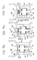
Fig. 1d and 1e illustrate, in fragmented cross-sectional transverse view, an enlarged view of a closing member of the valve according tofig. 1a - 1c in a static operating mode and in a dynamic operating mode, respectively, -
Fig. 1f and 1g illustrate, in fragmented cross-sectional transverse view, an enlarged view of the valve member offig. 1a - 1c in a static operating and in a dynamic operating mode, respectively, -
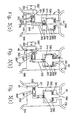
Fig. 2a - 2c illustrate, in a cross-sectional transverse view, the main elements of a valve according to a second embodiment of the invention in three different operating positions, -
Fig. 3a - 3c illustrate, in a cross-sectional transverse view, the main elements of a valve according to a third embodiment of the invention in three different operating positions, -
Fig. 4a - 4c illustrate, in a cross-sectional transverse view, the main elements of a valve according to a fourth embodiment of the invention in three different operating positions, -
Fig. 5 illustrates schematically the main elements of the preferred embodiment of a system according to the present invention, -
Fig. 6 illustrates schematically the main elements of a configuration of the pressure regulation means offig. 5 , -
Fig. 7 illustrates schematically the main elements of another embodiment of pressure regulation means offig. 5 and -
Fig. 8 illustrates changes in delivery pressure with respect to time for a typical filling operation using a system as shown infig. 5 - 7 . -
Fig. 1a - 1c illustrate a first and basic embodiment of the valve according to the present invention. Thevalve 10 comprises ahousing 20 with aninlet port 30 and anoutlet port 40. Achamber 50 is defined between theinlet port 30 and theoutlet port 40. Thechamber 50 may be in any suitable form, including one or more interconnected cavities, conduits or the like such as to provide fluid communication between theinlet port 30 and theoutlet port 40. - The upstream end of the
housing 20 and particularly theinlet port 30 is adapted for connection to a suitable fluid source 600 (seefig. 5 ). Connection may be made via asystem 700 according to the present invention. The fluid source may include any suitable source such a pressurized tank, a container or a fluid distribution system without being limited thereto. The downstream end of thehousing 20 and in particular theoutlet port 40 is adapted for connection to asuitable container 500 that is desired to be filled or refilled with a fluid from thesource 600. Such a container is typically in, but not limited to the form of a pressurizable cylinder. Thecontainer 500 comprises acontainer inlet 520 and a holdingvolume 550 for the fluid. The -housing 20 of thevalve 10 is preferably adapted for permanent connection to an opening of thecontainer 500. It can be formed integral therewith, welded thereto, bonded thereto or otherwise permanently joined thereto. A reversible connection, which can be useful for maintenance or repair, is also conceivable. In either case, when connected to thehousing 20, a fluid communication is established between the holdingvolume 550, thecontainer inlet 520 and theoutlet port 40 of thevalve 10. - The
housing 20 comprises a closing member in the form of a closingmember 60 that is reversibly movable, typically reciprocatingly, between a closed upstream position and an open downstream position. The closingmember 60 comprises aface seal 61 at an upstream end thereof that sealingly abuts avalve seat 21 comprised in an inner part of thehousing 20 at theinlet port 30 when it is in the upstream position. This position is shown inFig. 1a . For dispensing fluid from thecontainer 500 via the valve, a pin or a similar device may be inserted into theinlet port 30 to depress the closingmember 60 in a downstream direction. Alternatively, the first valve may be provided with a pin (not shown) projecting through theinlet opening 30. In the downstream position, theface seal 61 is distanced from the valve seal 21 (seefig. 1b ). Thus, fluid communication between theinlet port 30 and thus a fluid source connected to the inlet port and thechamber 50 in thevalve 10 is allowed. - Optionally, a suitable
downstream stop 25 may be provided in thehousing 20, placing a limit on the downstream position. The closing member can have any position from a minimally opened position just enabling fluid communication to the maximum open position illustrated infig. 1c , where the closingmember 60 is against thestop 25. - The closing
member 60 comprises anupstream face 62.Upstream face 62 may include aface seal 61. Delivery static pressure P1 from thesystem 700 acts on to theupstream face 62. The sealingassembly 60 further has a downstream facingsurface 63 on which the chamber static pressure P2 is acting. - The
face 62 comprises aprotrusion 66 which may have a closed shape such as a circle over the surface of theface 62. Theprotrusion 66 defines the sealing perimeter of theface seal 61 with respect to avalve seat 21. Under static conditions, the effective area of theface 62 is given by the enclosed area A1 bounded by theprotrusion 66. It is usually less than the corresponding area A2 of the surface 63 (seeFig. 1a - 1g ). - The condition for the closing member to open is that the downstream force F1 given by the product of the delivery pressure P1 and the effective area A1 is greater than the upstream force in the
chamber 50. The upstream force F2 is given by the product of the chamber pressure P2 and the area A1. Once the closingmember 60 is open and dynamic conditions exist, the effective area A1' of theface 62 becomes equal to the area A2 (seefig. 1e ). - The closing
member 60 is configured to move to the open downstream position responsive to a first force F1 of a minimum magnitude applied thereto. The minimum magnitude corresponds to a positive fluid static pressure difference ΔP1 (P1 - P2), which exists between theinlet port 30 and thechamber 50. The pressure difference may be generated during the operation of thevalve 10 after the initial opening force F1 provided by a sufficiently high delivery pressure P1≥P2. The closing member moves to the closed upstream position corresponding to a positive fluid pressure difference existing between thechamber 50 and theinlet port 30. Optional urging means (not shown) such as a coil spring may be provided to urge the closing member towards the closed upstream position. - The value of P2 will generally depend on the downstream back pressure P3 provided by the container. As the container fills up with fluid, P3 will increase and P2 will tend to equalise with P1. However, once the
first closing member 60 is fully open, the pressure P2 is still below P1 due to the restriction caused byinlet port 30, whether the fluid flowing therethrough is in the gaseous or liquid state. - The housing further comprises a
valve member 70 which is reversibly movable, typically reciprocatingly, between a first, open, upstream position and a second, closed, downstream position. Thevalve member 70 comprises aface seal 71 at a downstream end thereof that sealingly abuts avalve seat 22 comprised in an inner part of thehousing 20 at theoutlet port 40 when the valve member is in the second downstream position (seefig. 1c ). In the first upstream position (seefig. 1b ) theface seal 71 is distanced from thevalve seat 22 and allows fluid communication between thechamber 50 and theoutlet port 40 and thus also between acontainer 500 connected to theoutlet port 40. A suitableupstream stop 26 which can be integral with thedownstream stop 25 may be provided in thehousing 20 and place limit on upstream travel of thevalve member 70. The first position can include any position from minimally opened to the maximum open position shown infig 1a . - The
valve member 70 comprises anupstream face 72 on which acts chamber static pressure P2 and a downstream facingsurface 73 which may include aface seal 71, on which acts the back static pressure P3 from thecontainer 500. Theface 72 has aprotrusion 76 typically in the form of a closed shape such as a circle over the surface of theface 72 to define the sealing perimeter of theface seal 71 with respect to thevalve seat 22. Under static conditions, the effective area of theface 73 is given by the enclosed area A3 bounded by theprotrusion 76 and is generally less than the corresponding area A2 of thesurface 73. The condition for thevalve member assembly 70 to open is that the upstream force F3 given by the products of the back pressure P3 and the effective area A3 plus a balancing force provided by force-generatingmeans 80 is greater than the downstream force F2 in thechamber 50 given by the product of the chamber pressure P2 and the area A3. When thevalve member 70 is open and dynamic conditions exist, the effective area A3' of thelower face 72 becomes equal to the area A2. - The
valve member 70 is thus configured to move to said second position responsive to a third force F3 of predetermined minimum magnitude that may be applied to thevalve member 70 corresponding to a second positive fluid static pressure difference ΔP3 (= P2 - P3) that may exist between thechamber 50 and theoutlet port 40, generated for example during operation of thevalve 10. - When both, the closing
member 60 and thevalve member 70 are open, fluid flows from the fluid source to the container since the pressure difference P1-P3 is positive. The pressure P2 is still greater than P3 due to the restriction caused byoutlet port 40 and due to the fact that thecontainer 500 takes time to fill and does create the back pressure equal to P2, whether the fluid flowing therethrough is in the gaseous or liquid state. When the container is full of liquid, then P1, P2 and P3 equalise and no more fluid flow is possible. - Alternatively, the face seal and the valve seat arrangement for the closing
member 60 and thevalve member 70 may be replaced with other types of known sealing arrangements. While the closingmember 60 and thevalve member 70 are illustrated infig. 1a - 1c as reciprocatable along a common axis, thelongitudinal axis 100 of thevalve 10, each one of the closing and thevalve member axis 100 of thevalve 10. - The
valve 10 further comprises at least a part of a suitable force-generatingmeans 80. The force-generatingmeans 80 provides a balancing force Fx to thevalve member 70 at least during operation of thevalve 10. The force-generating means may be comprised in its entirety in the housing and thus continuously provide the required balancing force Fx. It may e. g. be in the form of a coiled spring. Alternatively, the force-generatingmeans 80 may be only partially comprised in thevalve 10 and in thehousing 20. A complementary part (see e. g.fig. 5 ) of the force-generating means 80 can be provided externally to thevalve 10 only during operation of thevalve 10 with a compatible and authorized fillingsystem 700. - When a nominally empty
suitable container 500 is connected to theoutlet port 40 such as to provide fluid communication there between, three different scenarios are possible for the valve 10: - a) The
container 500 may have a residual pressure, i. e. the container is not completely empty. In this case, the residual pressure maintains the closingmember 60 in the closed position as shown infig. 1a . Thevalve member 70 may be urged to the first position responsive to the balancing force Fx provided by the force-generatingmeans 80. If this force Fx is absent, thevalve member 70 may comprise any position within thehousing 20. This scenario a) may be routinely avoided by venting thecontainer 500 prior to refilling thereof. - b) The container may be at ambient pressure. The closing
member 60 is typically in the open position. It probably abuts thestop 25. Thevalve member 70 may be urged to the first, open position responsive to the balancing force Fx provided by the force-generatingmeans 80. If the balancing force is absent, thevalve member 70 may comprise any position in thehousing 20, typically.the second position. - c) Rarely, the
container 50 may be at a lower pressure than ambient pressure, e.g. when the container has been emptied at an altitude with low ambient atmospheric pressure and when it is desired to refill the container at a lower altitude. In this situation, the closingmember 60 is in the open position and abuts thestop 25. If the force-generatingmeans 80 is providing the balancing force Fx, this will be sufficient to overcome the vacuum effect and to open thevalve member 70 until pressure equalizes between thecontainer 500 and the ambient atmosphere. If the force Fx is absent, thevalve member 70 will remain at the closed second position. In such a case, the balancing force Fx must be generated to permit equalization of the pressures. - When an unauthorized fluid source is connected to the
valve inlet port 30, the relatively large fluid delivery pressure associated with such known sources generates a relatively large first force F1 opening the closingmember 60 and abutting the same against thestop 25. Almost simultaneously, the same high delivery pressure P2 provides a large second force F2 to thevalve member 70 due to the relatively large pressure difference with respect to the pressure P3 within thecontainer 500. The only force available to counter the large second force F2 is the balancing force Fx provided by the force-generatingmeans 80. If the magnitude of the force Fx is chosen such that it is to small to counter the force F2 in cases other than when there is a small static pressure difference across thevalve member 70, thevalve member 70 is moved into the closed position. - If it is attempted to fill the
container 500 at a constant delivery pressure of a low magnitude, the filling process will end as soon as the pressures are equalised. The container will only be partially filled. An unauthorised user attempting to fill the container by manually increasing the delivery pressure to keep the valve open will have difficulties to precisely control the delivery pressure. Fine controlling would inevitably require an extremely lengthy time period and such unauthorised user may be generally deterred. - If the
valve 10 only comprises an inner part of force-generating means, no balancing force Fx is provided unless the activity of the complementary external part 80' is duplicated by an unauthorised user. Thevalve member 70 will therefore shut. This applies when thevalve 10 and the container are in scenario b) or c). In scenario a), either there is no flow because the delivery pressure is less than or equal to the residual pressure in the container. If the delivery pressure is greater than the residual pressure, the pressure difference will immediately close the valve member if no balancing force Fx is provided. - The
fluid filling system 700 according to the invention is adapted for controlling the delivery pressure of the source 600 (seefigure 5 ) at least just upstream of thevalve inlet port 30. Filling is started with a very low delivery pressure. The delivery pressure is incremented in a predetermined manner. Essentially, starting at a low delivery pressure, the static pressure in thechamber 50 is also low and thus ΔP1 is small, giving rise to a small force F1 sufficient to open the closingmember 60. The closingmember 60 may also be kept in the open position by means of a mechanical pin or equivalent not shown in a similar manner to that used when it is desired to dispense fluid from thecontainer 500. - Although at this point, the static pressure P2 in the
chamber 50 increases as the fluid flows therethrough into the container, the difference in static pressure ΔP3 or P2-P3 between thechamber 50 and the container is small and the downstream force F2 generated thereby on thevalve member 70 is counteracted by the balancing force Fx. The magnitude of the balancing force Fx is chosen according to the type of fluid in thesource 60 and to the mechanical characteristics of thevalve 10. If the delivery pressure from thesource 600 at theinlet port 30 is even a little higher than a nominal starting value, ΔP3 will be greater than aforesaid and will generate a downstream force F2 which is greater than the balancing force Fx, causing thevalve member 70 to move to the second position and thus to close thevalve 10. As fluid flows throughvalve 10 into thecontainer 500, the static pressure P3 of thecontainer 500 begins to increase and thus eventually would equalise with the delivery pressure P1. This would result in thecontainer 500 being partially filled until the pressure equalises. If an unauthorised user wishes to circumvent thesystem 700 by providing a very low delivery pressure, the low amount of fluid that can be provided would act as deterrent for such unauthorised use. - According to the invention, the
fluid filling system 700 is adapted for incrementally increasing the delivery static pressure P1 at theinlet port 30 such as to maintain the pressure difference across the valve, i.e. P1-P2, and therefore ΔP3 substantially constant in registry with the increasing back pressure P3 of thecontainer 500, the value of ΔP3 being that to provide a force substantially equal to the balancing force FX. In other words, thesystem 700 first provides a very low delivery static pressure to theinlet port 30 and thus to thechamber 50, and as the back pressure from thecontainer 500 increases due to accumulation of fluid therein, the delivery pressure P1 is increased in a controlled manner such as to maintain ΔP3 constant, correlated to the value of the balancing force Fx. Only if a complimentary and authorised fillingsystem 700 is used, it is possible to completely fill thecontainer 500 within a reasonable time frame. - Instead of the embodiments shown in
figures 1a to 1g , different constructions of the valve are conceivable whereby the valves operate-as described above. According to the second embodiment shown infigures 2a to 2c , the closing member and the valve member are integrated into a single combinedvalve assembly 260. Thevalve sealing assembly 260 comprises aface seal 261 at an upstream end that sealingly abut avalve seat 221 comprised in an inner part of thehousing 220 at theinlet port 30, when in a closed upstream position (seefigure 2a ). For dispensing the fluid from thecontainer 500 via thevalve 210, the valve assembly typically comprises apin 290 that projects through theinlet opening 30. By depressing thepin 290, theassembly 260 is moved to open theinlet port 30. In the open downstream position (seefigure 2b ) theface seal 261 is distanced from thevalve seal 221 and allows fluid communication between theinlet port 30 and the chamber 250. Theassembly 260 comprises aface seal 271 at a downstream end thereof which sealingly abuts avalve seat 222 comprised in an inner part of thehousing 220 at theoutlet port 40 when it is in the closed position as shown infigure 2c . In the position shown infigure 2b , theface seal 271 is distanced from thevalve seal 222 and allows fluid communication between the chamber 250 and theoutlet port 40. The container can be filled when theassembly 260 is in the position shown infigure 2b . Theassembly 260 has anupstream face 262 on which acts delivery static pressure P1 from thesystem 700 and a downstream facingsurface 273 on which acts the back static pressure P3 from thecontainer 500. The effective areas, of thefaces assembly 260 is open and is operating dynamically. According to this embodiment, the force-generating means comprises aspring 280, typically a helical a spring, which abuts at its upstream end aspigot 270 that depends in a downstream direction from thevalve assembly 260 and which abuts at its downstream end asuitable shoulder 285 comprised in thehousing 220. When depressed, thespring 280 stores elastic potential energy and provides a restoring or a balancing force Fx in the upstream direction to thevalve assembly 260. When the force F1 provided as a result of the pressure difference between theinlet port 30 and theoutlet port 40 is to large, e.g. when it is attempted to fill thecontainer 500 without using an authorised system, this relatively large force overcomes the resistance of thespring 280, which compresses intorecess 286 enabling thevalve assembly 260 to move to a closed position so as to close the outlet port 40 (figure 2c ). - Such springs can be used with a valve member different from the one shown in
figures 2a to 2c . - A valve according to a third embodiment of the invention is shown in
figures 3a to 3c . It comprises all elements of the first embodiment of thevalve 10 as described above with the differences described herein below whereby like parts have like reference numerals increased by 300. Thevalve 310 comprises ahousing 320 with achamber 350, which is divided into anupper sub-chamber 351 and alower sub-chamber 352. Theupper sub-chamber 351 comprises aclosing assembly 360 movable therein. - The
lower sub-chamber 352 comprises thevalve member 370 movable therein. The closingmember 361 is formed in a similar way as in the second embodiment. Optionally, the closingmember 360 may comprise a restoringspring 374 which abuts at its upstream end aspigot 376 that depends in a downstream direction from the closingmember 360 and which abuts at its downstream end asuitable shoulder 385 comprised in thehousing 320. The restoringspring 374 urges the closingmember 360 into a closed position even when the static pressure in thevalve 310 is not greater than the external pressure and the force generated by thespring 374 is generally lower than the magnitude of first force F1 at least at the beginning of the filling process. When thespring 374 is fully compressed, there is still a fluid communication between theupper sub chamber 351 and the lower sub-chamber 352 (seefigure 3c ).Spring 374 is provided to ensure that thecontainer 500 is closed after it has been completely emptied in order to avoid contamination of the interior of thecontainer 500. - According to this embodiment, the force-generating means 80 comprise an
internal part 380" comprised in thevalve 310 and a complementaryexternal part 380 that is typically comprised in thesystem 700 according to the invention. Theinternal part 380" is in the form of amagnetic element 381 comprised in thevalve member 370. Infigures 3a to 3c , themagnetic element 381 forms the main body of thevalve member 370. It is reciprocatable in thelower sub-chamber 352 which may have itsaxis 200 orthogonal with respect to thelongitudinal axis 100 of thevalve 310. Themagnetic element 381 may also be separate to and included in thevalve member 370. Themagnetic element 381 is arranged such as to have a particular pole, e.g. its north pole, facing towards the outside of thehousing 320 and thus typically also away from theaxis 100 of thevalve 310. Themagnetic element 381 is arranged aligned with theaxis 200 of the lower sub-chamber 325. The complementary part 380' also comprises amagnetic element 382. If the complementary part 380' of the force-generating means is brought into proximity with thevalve 310 such that similar poles are facing each other as shown infigure 3a to 3c , theexternal part 380 has its north pole facing the north pole of themagnetic element 381. The balancing force Fx in this embodiment is provided by the magnetic repulsion between themagnetic elements face seal 361 away from thevalve seat 322. If it is attempted to use thevalve 310 with asystem 700 without an external part 380', no balancing force Fx will be generated and thevalve member 370 is free to move back to a closed position. As soon as theinlet port 30 of thevalve 310 is exposed to a delivery pressure above the static pressure in thecontainer 500, thevalve member 370 closes theoutlet port 40. - The valve according to the forth embodiment of the invention shown in
figures 4a to 4c comprises all the elements of the first embodiment of thevalve 10 with the difference described herein below. Reference numerals increased by 400 refer to similar parts as in the third embodiment. The downstream end of thespring 474 is accommodated in a suitable well 485 comprised in thehousing 420 as compared to the accommodation of the downstream end of the spring in the third embodiment. The main difference between this embodiment and the third embodiment is, that in this embodiment the force-generatingmeans 80 operates by means of magnetic attraction between two elements, rather than by magnetic repulsion. Theinternal part 480" in the forth embodiment may be in the form of amagnetisable element 481 comprised in thesecond valve member 470. It may comprise a ferrous core and form the main body of thevalve member 470. During proper operation of thevalve 420, a complementary part 480' of force-generatingmeans 80 is brought into proximity with the valve 410 such that one of the poles of themagnetic element 482 is aligned with the axis 300 of thevalve member 470. The balancing force Fx in this embodiment is provided by the magnetic attraction between themagnetic element 482 and themagnetisable element 481. The operation of the valve according to the force embodiment is similar to the operation of-the valve according to the third embodiment. Alternatively, theinternal part 480" of the force-generatingmeans 80 may comprise a magnetic element with its poles arranged such as to provide a magnetic attraction force when brought in operative connection with an external part 480' of thefilling system 700. - As mentioned above, the force-generating
means 80 is calibrated to provide a suitable balancing force Fx of a magnitude that is chosen according to the fluid being used in conjunction with the valve according to the invention. When the fluid is a liquid with low evaporation point, such as petrol and the like, or a gas with low liquefaction point, for example carbon dioxide, it quickly forms a liquid deposit in thecontainer 500 which is otherwise filled with the gaseous or vapour phase of the liquid, which in turn provides aforesaid back pressure P3. - This back pressure generally depends on the nature of the fluid and the temperature thereof and varies from fluid to fluid. As soon as some liquid forms in the container the vapour pressure remains constant as more liquid forms, so long as the temperature remains constant. In practice, however, the expansion of the gas into the
container 500 results in the cooling thereof and thus in a lower vapour pressure than at ambient temperature. As thecontainer 500 is filled some more and the temperature stabilises and begins to increase, the vapour pressure similarly increases and eventually stabilises being a function of the temperature in thecontainer 500 and independent of the level of liquid phase therein so long as some minimum quantity thereof exists therein. - Essentially, then, for all embodiments, the valve member remains open during filling operation of the container when the positive pressure difference between the delivery fluid pressure P1 and the container fluid pressure P3 (that is the positive pressure difference ΔP13 between the first and/or the second end of the valve) is not greater than a particular value such that the causing force acting on the valve member corresponding to the pressure difference may be countered by the balance force Fx and does enable the valve to remain open.
- Thus for a given fluid delivery pressure, the value of Δp13 will vary, according to the particular vapour pressure of the fluid. Since the magnitude of the balancing force Fx is related to Δp13, account must be taken of the nature of the fluid when choosing Fx. Thus, for example, if a valve in which the force-generating means-80 provides a particular balancing force that is appropriate for carbon dioxide, that has a relatively large vapour pressure, is used for filling a
container 500 with a fluid of lower vapour pressure, the balancing force Fx would be insufficient to maintain thesecond valve assembly 70 open. This is because the magnitude of Δp13 provided by the system would result in a force that is larger than Fx, causing the corresponding valve member to close. On the other hand, if it is attempted to use the same valve with a fluid having substantially higher vapour pressure than the nominal value for the valve, than the valve can still operate. - On the other hand, gases with very low liquefaction point, such as O2, N3 and so on, behave more or less as ideal gases, and thus the back pressure will continually increase as the delivery pressure increases.
- The valve according to the present invention is therefore adapted to operate, i.e., to enable a container attached thereto to be filled, only under specific conditions:
- a) that a suitable balancing force Fx is present at least during filling of the reservoir, and
- b) when the delivery pressure P1 at the inlet port of the valve begins at a specific very low magnitude and is subsequently increased in a manner such as to provide a closing force to the valve member that is not greater than the balancing force generated by the force-generating means of the valve, as the back pressure P3 from the reservoir increases.
- Accordingly, the
fluid filling system 700 according to the invention comprises the features necessary-to provide these conditions. - Thus, and as illustrated schematically in
Figure 5 , a preferred embodiment of thefluid filling system 700 of the present invention comprises a suitable pressure regulating means 720 operatively connectable to thefluid source 600, and a suitable fluid flow rate sensor means 730 operatively connected to the pressure regulating means 720 and operatively connectable to thevalve 10 according to the invention. While thevalve 10 according to the first embodiment of the invention is schematically illustrated inFigure 5 , the description of thesystem 700 is similarly applicable to other embodiments of the valve, mutatis mutandis. Thesystem 700 further comprising suitable control means 710 operatively connected to the pressure regulating means 720 and to the fluid flow rate sensor means 730, and provides control of the pressure regulating means 720 according to the fluid flow rate measured by the fluid flow rate sensing means 720. - According to the type of
valve 10 used with thesystem 700, thesystem 700 may also comprise a complementary external part 80' of said force-generating means 80 such that when thevalve 10 is operatively connected to thesystem 700, and at least when thesystem 700 is in operation, an appropriate balancing force Fx is generated in thevalve 10. - The pressure regulating means 720 comprises any suitable pressure regulator arrangement capable of delivering a delivery fluid pressure P1 that is initially very low at its output, regardless of the magnitude of the fluid pressure of the
fluid source 600 connected thereto. Further, the pressure regulating means 720 is capable of being finely controlled such as to increase the output fluid pressure thereof in very small steps. Such steps may be optimised, since steep changes in pressure with respect to time may result in the valve member closing, while shallow changes in pressure with respect to time reduces the filling efficiency, resulting in long refill time for thecontainer 500. One optimum pressure change rate found by the applicants for filling a reservoir with CO2 is about 4 bars in 2 seconds. - Optionally, and as illustrated in
Figure 6 the pressure regulating means 720 may comprise apressure regulator 810, that is connectable to thesource 600 via any suitable conduit and/orconnectors 805. Anair pressure source 830 provides air at a predetermined high pressure to aproportional valve 840, which is operatively connected to the control means 710 viacommunication line 845, which serves as an additional pressure regulator that can be used to operate thepressure regulator 810. Such an arrangement may be useful when off the shelf components for the elements inFigure 6 provide the required control over the delivery pressure, which in turn is in fluid communication with thepressure regulator 810. When the control means 710 determines that an increase in delivery pressure is required from the pressure regulating means 720, an appropriate signal is sent to theproportional valve 840 which then increases its output pressure with respect to thecylinder 850 which in turn opens thepressure regulator 810 such as to provide the desired delivery pressure to thevalve 10. The control means operate in a manner known to those skilled in the art. - One advantage in using the pressure regulating means 720 of
Figure 6 is that a sufficiently sensitive and controllable pressure regulation may be provided using off-the-shelf components. - Optionally, and typically the
system 700 further comprisessuitable scales 770 or other weighing means for determining the mass or weight of thecontainer 500 at least before the filling procedure and at the end thereof, to ensure that the container has been filled with the required amount of fluid. Preferably, thescales 770 enable the weight or mass of the container to be continually monitored during the filling operation and advantageously, thescales 770 are operatively connected to the control means 710 and are adapted for transmitting thereto a signal representative of the weight or mass of thecontainer 500. Thus, the control means 710 continually monitors the weight or mass of thecontainer 500 during the filling procedure. This has the advantage that if the second valve sealing means closes while the container is not yet full or within a proportion thereof, say 98% full as indicated by the low weight of mass value provided from thescales 770 to the control means 710 this indicates that the delivery pressure was too high rather than the container is full. Thus, this configuration enables the control means 710 to distinguish between a situation where the container is full to one where the cause of the valve member closing is high delivery pressure. In this case, flowrate sensor 730 could also be omitted. - Alternatively, and as illustrated in
Figure 7 , the pressure regulating means 720 may comprise, as before, apressure regulator 810 such as for example, that is connectable to thesource 600 via any suitable conduit and/orconnectors 850. However, thepressure regulator 810 is connected to a suitablestepper motor arrangement 860 that is adapted to enable thepressure regulator 810 to increase or decrease the delivery pressure in small steps correlated to the stepping action of themotor 860.Such stepper motors 860 are well known in the art. Thestepper motor 860 is operatively connected to the control means 710 viacommunication line 845. When the control means 710 determines that an increase in delivery pressure is required from the pressure regulating means 720, an appropriate signal is sent to-thestepper motors 860, which then rotates by the required number of incremental steps, which in turn opens thepressure regulator 810 by a corresponding amount such as to provide the desired delivery pressure to thevalve 10. - Advantages in using the pressure regulating means 720 of
Figure 7 include that a sufficiently sensitive and controllable pressure regulation may be provided using off-the-shelf components, and that less components are required relative to the arrangement ofFigure 6 . - The fluid flow sensing means 730 comprises any suitable fluid flow sensor or sensors capable of sensing and measuring fluid flow rates, either mass flow rate or volume flow rate or both typically from very small values such as for example a few standard cubic centimetres (sccm) to nominal flow rates including for example a few standard litres per second, and to detect small changes in the flow rate. Further the flow rate sensing means is capable of converting the fluid flow rate measured thereby into appropriate signals, typically electrical or electronic, either analogue or digital, capable of being received and processed by said control means 710. The fluid flows sensing means typically comprise a flow meter. Suitable flow meters are known in the art. Such flow meters typically provide RPM of a turbine comprised therein as a function of the flow rates passing therethrough.
- The control means 710 typically comprises a micro-processor based control system, such as for example a computer externally connected to the
system 700, or alternatively, and preferably, a suitable microprocessor chip integrally comprised in thesystem 700. In particular, the control means 710 is adapted for receiving suitable signals from the fluid flow sensing means 730 and based on these signals to provide control signals to the said pressure regulating means 720 to control the delivery output pressure P1 provided thereby. - The
system 700 is normally integrally or permanently connected to a suitablefluid source 600 via the pressure regulating means 720 but could be removably connected thereto, for example to facilitate maintenance of thesource 600 orsystem 700. When it is desired to fill acontainer 500, thesystem 700 is connected to a valve 10 (which is typically, permanently connected to container 500) via the fluid flow rate sensing means 730. Alternatively, the flow sensing means 730 may be connected to thefluid source 600, and the pressure regulating means 720 may be connected to thevalve 10 mutatis mutandis. At the start of a normal filling operation of thesystem 700 the control means 710 commands the pressure regulating means to provide a delivery pressure P1 of relatively very low magnitude, such as to provide a differential pressure Δp13 that generates a force to the valve member that is not greater than the balancing force Fx provided by the force-generatingmeans 80. Since the control means 710 is calibrated for a specific type ofvalve 10 the precise starting delivery pressure P1 that is required for operating thevalve 10 is known. - Optionally, the control means 710 may be programmed for use with a plurality of
valves 10 and/or for use with a multitude of different types of valves, and thus may control eachvalve 10 separately or simultaneously in a similar manner to that described herein, mutatis mutandis. - If at the tart of the filling procedure the flow rate sensing means 730 measures a zero flow rate, this is indicative of scenario a), i.e., that the container has a residual pressure, and thus that the delivery pressure is insufficient to open the closing
member 60, thecontainer 500 can be removed, emptied and connected to thesystem 700 viavalve 10. Alternatively, mechanical means such as a suitable pin arrangement may force the closingmember 60 to open when the valve is connected to thesystem 700. Alternatively, and preferably, a suitable blow-off orpressure release valve 740 may be used to bleed thecontainer 500 prior to use, as will be further described herein below. - Typically, particularly in scenario b), a small fluid flow rate will be initially detected by the fluid flow rate sensing means 730 at the beginning of operations. As marked G in
figure 8 , delivery pressure P1 typically starts at nominally zero, increasing rapidly until a back pressure P3 is detected, limiting P1 such that the positive pressure difference does not exceed Δp13. Referring to fluids such as CO2 that have relatively high liquefaction points. As thecontainer 500 begins to fill with fluid, the static pressure P3 in thecontainer 500 increases and this part of the filling operation is marked A infigure 8 , wherein the fluid is exclusively in the gaseous phase incontainer 500. The increase in delivery pressure P1 with respect to time, may be optimised so that on the one hand it is not too high A' resulting in closure of the valve member, and not too low A" resulting in a long refill time. Preferably, the positive pressure difference Δp13 is kept constant and less than or equal to a pressure difference with respect to which the balance force Fx is calibrated. Eventually, liquid begins to form in thecontainer 500, marked B infigure 8 , and the fluid delivered via the valve comprises an increasing proportion of liquid with respect to the gaseous phase. Accordingly it is possible to increase the rate of change of delivery pressure P1 with time to a new value, to decrease the filling time, maintaining however the same pressure difference at least or equal to Δp13. At a certain point when a predetermined amount of liquid is formed in the container, for example when the net weight of the contents has reached 50g, the system increases the rate of change of pressure to still a higher value, again maintaining the pressure difference across the valve at least or equal to Δp13. When a critical amount of liquid has been deposited in the container, such that the vapour pressure is constant (the temperature also having stabilised), thereafter there is a more or less constant vapour pressure as more fluid is provided to the container, marked C in the figure. Thereafter the delivery pressure P1 is kept constant at the value corresponding to the vapour pressure plus Δp13 marked C in the figure. Typically fluid flow is terminated when the net weight of the container contents reaches a predetermined limit. Otherwise, however, the container fills fully with liquid phase of the fluid, the back pressure P3 suddenly increases when the container is full, equalising with the delivery pressure P1 marked F in figure 10. However, during the initial mixed vapour/liquid filling phase indicated at A infigure 8 , as more fluid is provided to the container, at some point, the vapour pressure increases as the temperature therein increases and eventually the back pressure in the cylinder equalises with the delivery pressure, so that the fluid flow rate commensurately diminishes towards zero and the delivery pressure P1 needs to be increased. - Accordingly, the control means 710 interprets a diminishing fluid flow rate sensed by the fluid flow rate sensing means 730 as indicating that the back pressure P3 from the container is increasing, and thus sends an appropriate signal to the pressure regulating means 720 to increase the delivery pressure P1 of the fluid. Thus, part A of
figure 8 , rather than being a smooth gradient may comprise a wavy profile as the delivery pressure P1 is changed in small increments according to changes in the measured mass flow. - Thus, in this manner, the control means 710 continually monitors the fluid flow rate measured by the fluid flow sensing means 730, and continually increases in very small steps the delivery pressure P1 provided by the pressure regulating means 720 whenever the fluid flow rate decreases. Thus, preferably, the control means 710 attempts to maintain a constant fluid flow rate into the container, or alternatively within an upper flow rate limit and a lower flow rate limit. Preferably, though, the control means 710 attempts to maximise the fluid flow rate into the
container 500. - If for any reason the pressure regulating means 720 increases the delivery pressure P1 by too much, this leads to the
valve member 70 closing theoutlet port 40, and thus the fluid flow rate suddenly drops to zero. A zero fluid flow measured by the fluid flow sensing means 730 is always interpreted by the control means 710 to signify that thevalve member 70 has closed, and under the circumstances i.e. when part of the container has already been filled, the control means 710 commands the pressure regulating means 720 to reduce the delivery pressure. However, when the fluid is a gas with low liquefaction point such as CO2 for example, the flow sensing means 730 may be sensitive only to the flow of liquid and not to the flow of gas. Thus, at the beginning of the filling operation, marked A infigure 8 , when only gas is flowing into thecontainer 500, the flow sensing means will not sense any flow. However, the control means 710 can be programmed for this. Only once some liquid has formed in the container, then liquid flows through the flow sensing means 730, which then senses the flow. - At the same time, an optional
pressure release valve 740 releases pressure between the pressure regulating means 720 and thechamber 50 of thevalve 10, and fluid therein is vented into the atmosphere or tooptional overflow tank 750. Thus, thepressure release valve 740 is operatively connected to and controlled by, the control means 710 and operation of thepressure release valve 740 is discontinued when the pressure P2 in thevalve 10, in particular in thechamber 50, has reduced sufficiently such as to enable thevalve member 70 to open theoutlet port 40. The delivery pressure P1 to thevalve 10 can be advantageously monitored by means of an optical pressure transducer or other pressure sensor means 760, preferably disposed downstream of the pressure regulating means 720, and operatively connected to the control means 710. Once the static pressure in the valve has been sufficiently reduced, such as to open thevalve member 70, fluid will once again flow into thecontainer 500, and the control means 710 continues to increase the delivery pressure P1 of the pressure regulating means 720, as herein before described. Preferably, prior to filling acontainer 500, thepressure release valve 740 releases pressure between the pressure regulating means 720 and thechamber 50 of thevalve 10.
Claims (23)
- A valve (10) for closing a container (500) and for enabling the container (500) to be filled, said valve (10) comprising a housing (20) with an inlet port (30) and an outlet port (40) wherein said inlet port (30) is adapted for direct or indirect connection to a fluid source (700) and wherein said outlet port (40) is adapted for direct or indirect connection to said container (500);
a closing member (60; 260; 360; 460);
and at least one valve member (70; 270; 370; 470) which in a first position allows fluid communication between said inlet port (30) and said outlet port (40) and which, in a second position, prevents fluid communication from said inlet port (30) to said outlet port (40),
wherein said valve member (70; 270; 370; 470) is brought into and maintained in said first position only if a static pressure difference (ΔP3) across said valve member (70; 270; 370; 470) is below a pre-determinable first threshold. - A valve according to claim 1, wherein said valve member (70; 270; 370; 470) has force-generating means (80; 280; 380" , 80'; 480" , 80') adapted for providing a balancing force (Fx) to said valve member (70; 270; 370; 470) and for bringing said valve member (70; 270; 370; 470) into said first position when said filling condition is fulfilled.
- A valve according to claim 2, wherein said force-generating means have a spring (280).
- A valve according to one of the claims 1 to 2, wherein the valve member (370; 470) has an internal part (380" , 480") comprised in said valve which can be operatively connected with an external part (80; 380'; 480') not comprised in said valve (10) for bringing and maintaining said valve member (370; 470) into said first position.
- A valve according to claim 4, wherein said internal part (380"; 480") has a first magnet (381) or a magnetisable element (481) providing a balancing force (Fx) for bringing said valve member (370; 470) into said first position when said valve is brought into proximity with an external part (380'; 480') having a second magnet (382; 482).
- A valve according to one of the claims 1 to 5, wherein said closing member (60; 260; 360; 460) is formed as a check valve.
- A valve according to claim 6, wherein said check valve (260) and said valve member (270) are formed on a body (260) movable in a chamber (50) of said housing (20) between said inlet port (30) and said outlet port (40).
- A valve according to one of the claims 6 or 7, wherein said check valve (260) comprises a pin (290) attached to an end of said check valve (260) directed towards said inlet port (30).
- A valve according to one of the claims 7 to 8, wherein said housing has a chamber divided in to an upstream chamber (251) and a downstream chamber (352) in communication with one another, wherein said upstream chamber (351) is adapted for reciprocatingly accommodating said closing member (60) wherein said downstream chamber (352) is adapted for reciprocatingly accommodating said valve member (370) at least between said first and second position.
- A valve according to one of the claims 5 and 9, wherein said downstream chamber (352) is adapted for aligning movement of said valve member (370) in the direction of magnetic attraction or repulsion between an internal part (380"; 480") and an external part (380'; 480').
- A system for filling a container (500) with a fluid exclusively from an authorised fluid source (700), comprising a pressure regulating means (720) in fluid communication to said fluid source (700) and adapted for connection with a valve (10) on said container (500) according to one of the claims 2 to 12, wherein said pressure regulating means (720) is designed to maintain the pressure of the fluid supplied to said container (500) below a pre-determined or pre-determinable first threshold selected in such a way that said valve member (70; 270; 370; 470) of said valve (10) is brought into and maintained in said first position.
- A system according to claim 11, wherein said system has fluid flow rate sensing means (730) for measuring the flow of liquid into said container (500), said system further comprising control means (710) operatively connected to said pressure regulating means (720) and said fluid flow rate sensor means (730).
- A system according to claim 11 or 12, wherein said pressure regulating means (720) is adapted for providing a delivery pressure of a pre-determined minimum magnitude and for increasing the delivery pressure in a manner controllable via said control means (710).
- A system according to one of the claims 11 to 13, wherein during operation of the system relating to the filling of a container (500) from a fluid source (699) connected to that system, said control means initially commands the pressure regulation means to provide a delivery pressure of a magnitude below a first predetermined threshold value and then to increase the delivery pressure, maintaining the fluid flow rate within a pre-determined range.
- A system according to one of the claims 11 to 14, wherein the system further comprises an external part (380'; 480') of said force-generating means which can be brought in operative connection with an internal part (380"; 480") of a force-generating means in a valve according to one of the claims 4 to 10.
- A system according to one of the claims 11 to 15, wherein the system comprises means for weighing (770) said container (500) coupled to said control means (710).
- A container for storing fluids, wherein said container is provided with a valve according to one of the claims 1 to 10.
- A container according to claim 17, wherein the valve is permanently connected to an opening of said container (500).
- A method for filling a container (500) having a valve (10) according to one of the claims 1 to 10 with a fluid from a fluid source (600), comprising the stepsa) connecting the valve (10) to said fluid source (600)b) controlling the delivery pressure (P1) of said fluid at an inlet port (30) of said valve (10) such as to maintain the static pressure difference (ΔP3) across a valve member (70; 270; 370; 470) of said valve below a predetermined or predeterminable first threshold.
- A method according to claim 19, wherein step b) comprises the sub-steps ofb1) initially providing a static delivery pressure to said inlet port (30) of said valve (10) that is less than a predetermined second threshold during a pre-determined or predeterminable period of timeb2) after step b1, increasing said delivery pressure continuously or in a plurality of steps.
- A method according to one of the claims 19 or 20, wherein step b comprises the sub-steps ofb3) initially providing a delivery static pressure to said inlet port which is less than a second threshold valueb4) measuring the fluid flow rate of fluid flowing into said valve (10)b5) if said fluid flow rate is decreasing, then increasing the magnitude of said delivery static pressure (P1) in a predetermined or predeterminable mannerb6) continuing steps b4 and b5 until the measured fluid rate is zero.
- A method according to one of the claims 19 to 21, wherein step b) comprises the further sub steps ofb7) measuring the static pressure at said inlet port (30)b8) if said static pressure in said step is within a pre-determined third threshold value of the magnitude of the pressure of the container when full, discontinuing filling of container and disconnecting the valve from said fluid sourceb9) if said static pressure in step b7 is less than a pre-determined third threshold value of the magnitude of the pressure of the container when full, discontinuing filling of container, releasing pressure in the valve upstream of the outlet port (40), resuming filling of container and continuing with steps b7) to b8).
- A method according to one of the claims 19 to 22, wherein before and/or during the filling procedure, the weight of the container (500) is continuously measured.
Priority Applications (1)
| Application Number | Priority Date | Filing Date | Title |
|---|---|---|---|
| SI200332603T SI2273179T1 (en) | 2002-07-18 | 2003-06-20 | A valve for closing a container |
Applications Claiming Priority (3)
| Application Number | Priority Date | Filing Date | Title |
|---|---|---|---|
| EP20020015978 EP1382899A1 (en) | 2002-07-18 | 2002-07-18 | A valve for closing a container, container and a system and method for filling a container |
| EP03740297.1A EP1523638B1 (en) | 2002-07-18 | 2003-06-20 | A valve for closing a container, container and a system and method for filling a container |
| PCT/EP2003/006526 WO2004010046A1 (en) | 2002-07-18 | 2003-06-20 | A valve for closing a container, container and a system and method for filling a container |
Related Parent Applications (3)
| Application Number | Title | Priority Date | Filing Date |
|---|---|---|---|
| EP03740297.1A Division EP1523638B1 (en) | 2002-07-18 | 2003-06-20 | A valve for closing a container, container and a system and method for filling a container |
| EP03740297.1A Division-Into EP1523638B1 (en) | 2002-07-18 | 2003-06-20 | A valve for closing a container, container and a system and method for filling a container |
| EP03740297.1 Division | 2003-06-20 |
Publications (3)
| Publication Number | Publication Date |
|---|---|
| EP2273179A2 true EP2273179A2 (en) | 2011-01-12 |
| EP2273179A3 EP2273179A3 (en) | 2018-02-28 |
| EP2273179B1 EP2273179B1 (en) | 2019-08-07 |
Family
ID=29762650
Family Applications (3)
| Application Number | Title | Priority Date | Filing Date |
|---|---|---|---|
| EP20020015978 Withdrawn EP1382899A1 (en) | 2002-07-18 | 2002-07-18 | A valve for closing a container, container and a system and method for filling a container |
| EP10183372.1A Expired - Lifetime EP2273179B1 (en) | 2002-07-18 | 2003-06-20 | A valve for closing a container |
| EP03740297.1A Expired - Lifetime EP1523638B1 (en) | 2002-07-18 | 2003-06-20 | A valve for closing a container, container and a system and method for filling a container |
Family Applications Before (1)
| Application Number | Title | Priority Date | Filing Date |
|---|---|---|---|
| EP20020015978 Withdrawn EP1382899A1 (en) | 2002-07-18 | 2002-07-18 | A valve for closing a container, container and a system and method for filling a container |
Family Applications After (1)
| Application Number | Title | Priority Date | Filing Date |
|---|---|---|---|
| EP03740297.1A Expired - Lifetime EP1523638B1 (en) | 2002-07-18 | 2003-06-20 | A valve for closing a container, container and a system and method for filling a container |
Country Status (24)
| Country | Link |
|---|---|
| US (1) | US7264024B2 (en) |
| EP (3) | EP1382899A1 (en) |
| JP (1) | JP2005539178A (en) |
| KR (1) | KR100977506B1 (en) |
| CN (1) | CN100564992C (en) |
| AR (1) | AR040499A1 (en) |
| AU (1) | AU2003281541B2 (en) |
| CA (1) | CA2492356A1 (en) |
| CY (2) | CY1121739T1 (en) |
| DK (2) | DK1523638T3 (en) |
| ES (2) | ES2725113T3 (en) |
| HU (2) | HUE046103T2 (en) |
| IL (2) | IL166081A0 (en) |
| LT (1) | LT1523638T (en) |
| NO (1) | NO339762B1 (en) |
| NZ (1) | NZ537667A (en) |
| PL (1) | PL206250B1 (en) |
| PT (2) | PT1523638T (en) |
| RU (1) | RU2311586C2 (en) |
| SI (2) | SI2273179T1 (en) |
| TR (1) | TR201906464T4 (en) |
| TW (1) | TW200403407A (en) |
| WO (1) | WO2004010046A1 (en) |
| ZA (1) | ZA200500401B (en) |
Families Citing this family (21)
| Publication number | Priority date | Publication date | Assignee | Title |
|---|---|---|---|---|
| US7363824B2 (en) * | 2004-06-16 | 2008-04-29 | Robert Buck | Flow sensor |
| US8100302B2 (en) * | 2004-09-08 | 2012-01-24 | Mark Bonner | Pump and nozzle liquid flow control system |
| US7339476B2 (en) * | 2004-11-10 | 2008-03-04 | Rockwell Automation Technologies, Inc. | Systems and methods that integrate radio frequency identification (RFID) technology with industrial controllers |
| US20060255069A1 (en) * | 2005-04-19 | 2006-11-16 | Fuel Transfer Technologies Inc. | Container apparatus for storing and dispensing liquid |
| DE102005048053A1 (en) * | 2005-10-07 | 2007-04-12 | Voith Patent Gmbh | Measuring device, in particular for measuring dewatering quantities of paper machines |
| US20070151621A1 (en) * | 2006-01-05 | 2007-07-05 | Honeywell International Inc. | Automatic shutoff and metering device |
| US7459008B2 (en) * | 2006-03-16 | 2008-12-02 | Aylsworth Alonzo C | Method and system of operating a trans-fill device |
| NZ594745A (en) | 2009-01-28 | 2012-12-21 | Fuel Transfer Technologies Inc | An automatic shut-off nozzle for use in a non-overflow liquid delivery system with a liquid recovery conduit |
| FR2974402B1 (en) * | 2011-04-22 | 2013-05-03 | Air Liquide | PRESSURIZED FLUID VALVE, TANK AND FILLING METHOD THEREOF |
| FR2978432B1 (en) * | 2011-07-26 | 2014-12-05 | Air Liquide | FILLING FITTING, CONTAINER, FILLING METHOD AND PACKAGING |
| USD679933S1 (en) | 2011-11-22 | 2013-04-16 | Primo Products, LLC | Beverage maker |
| LU92040B1 (en) * | 2012-07-09 | 2014-01-10 | Luxembourg Patent Co | Regulator valve with residual pressure function integrated in the regulator |
| US10179690B2 (en) * | 2016-05-26 | 2019-01-15 | Rai Strategic Holdings, Inc. | Aerosol precursor composition mixing system for an aerosol delivery device |
| WO2018097853A1 (en) * | 2016-11-23 | 2018-05-31 | Inventure Labs Llc | Fluid storage container |
| FR3081965B1 (en) * | 2018-06-04 | 2020-05-08 | L'air Liquide, Societe Anonyme Pour L'etude Et L'exploitation Des Procedes Georges Claude | DEVICE FOR PROVIDING PRESSURE FLUID |
| GB201813792D0 (en) | 2018-08-23 | 2018-10-10 | Davies Philip Andrew | Desalination system and method |
| FR3093781B1 (en) | 2019-03-12 | 2021-02-12 | Air Liquide | Valve, pressurized fluid container and methods of filling and withdrawing. |
| CN110043697B (en) * | 2019-04-30 | 2020-05-12 | 浙江独创空间智能科技有限公司 | Two-way check valve and related device |
| DE102019120241A1 (en) * | 2019-07-26 | 2021-01-28 | Bayerische Motoren Werke Aktiengesellschaft | Pressure vessel arrangement |
| WO2021102511A1 (en) * | 2019-11-26 | 2021-06-03 | Invertigro Pty Ltd | Fast filling and draining valve assembly and associated system |
| FR3107584B1 (en) * | 2020-02-24 | 2022-06-24 | Plastic Omnium Advanced Innovation & Res | Device for automatic obstruction of a filling circuit of one or more reservoir(s) of a fluid |
Citations (5)
| Publication number | Priority date | Publication date | Assignee | Title |
|---|---|---|---|---|
| US3674061A (en) | 1969-10-29 | 1972-07-04 | Wiggins Inc E B | Liquid transfer apparatus with pressure-sensitive automatic shut-off nozzle |
| US4195673A (en) | 1978-11-20 | 1980-04-01 | General Motors Corporation | Fuel tank fill tube with a magnetically actuated valve |
| US5474115A (en) | 1994-08-04 | 1995-12-12 | Husky Corporation | Specialty fuel dispensing nozzle |
| US5487404A (en) | 1993-07-12 | 1996-01-30 | Torrent Trading Ltd. | Valve for a tap of a compressed or liquified gas cylinder, and tap provided with such a valve |
| WO2000077442A1 (en) | 1999-06-15 | 2000-12-21 | Sparkling Krämer Gmbh | Refillable co2 gas cylinder and method of filling the same |
Family Cites Families (19)
| Publication number | Priority date | Publication date | Assignee | Title |
|---|---|---|---|---|
| FR1116274A (en) * | 1954-12-10 | 1956-05-07 | Automatic sealing device for damaged pressurized fluid lines | |
| US2977978A (en) * | 1957-11-25 | 1961-04-04 | Fairchild Engine & Airplane | Relief valve |
| US4056133A (en) * | 1976-04-19 | 1977-11-01 | Weil-Mclain Company, Inc. | Fluid flow control apparatus and a gasoline dispensing and vapor recovery system utilizing said apparatus |
| DE8402594U1 (en) * | 1984-01-31 | 1984-06-28 | Dittbrenner, Gerhard, Winnipeg | SAFETY VALVE |
| CA1220403A (en) * | 1984-05-15 | 1987-04-14 | Brian Tepsa | Gas fuse |
| US4537384A (en) * | 1984-07-17 | 1985-08-27 | Brunswick Corporation | In-line check valve having combined downstream poppet support and flow control elements |
| NO870619L (en) * | 1986-02-18 | 1987-08-19 | Eidsmore Paul G | VALVE. |
| DE4037905A1 (en) * | 1990-11-28 | 1992-06-04 | Herion Werke Kg | SAFETY VALVE |
| US5259424A (en) * | 1991-06-27 | 1993-11-09 | Dvco, Inc. | Method and apparatus for dispensing natural gas |
| JP3346604B2 (en) * | 1993-06-16 | 2002-11-18 | オリンパス光学工業株式会社 | Real image type zoom finder |
| DE59404467D1 (en) * | 1993-11-08 | 1997-12-04 | Burckhardt Ag Maschf | Method and device for the rapid refueling of a pressure container with a gaseous medium |
| US5488978A (en) * | 1994-05-02 | 1996-02-06 | Gas Research Institute | Apparatus and method for controlling the charging of NGV cylinders from natural gas refueling stations |
| JPH08161057A (en) * | 1994-12-07 | 1996-06-21 | Shinei Kogyo Kk | Pressure control valve |
| JP3038681B2 (en) * | 1995-12-13 | 2000-05-08 | サンデン株式会社 | Compressor safety valve |
| FR2779067B1 (en) * | 1998-05-29 | 2000-08-18 | Inst Francais Du Petrole | DEVICE FOR CONTROLLING THE FLOW OF AT LEAST ONE FLUID OF SEPARATION UNITS PER SIMULATED MOBILE BED |
| NL1009812C2 (en) * | 1998-08-05 | 2000-02-08 | Euro Maintenance Lease Prod Bv | Shut-off valve for a container. |
| AT411385B (en) * | 2000-04-28 | 2003-12-29 | Oberoesterreichische Ferngas A | SAFETY VALVE FOR A GAS SUPPLY PIPE |
| DE10222936A1 (en) * | 2002-05-24 | 2003-12-04 | Zahnradfabrik Friedrichshafen | Proportional pressure control valve |
| DE10224430A1 (en) * | 2002-06-01 | 2003-12-11 | Bosch Gmbh Robert | Non-return valve for a fuel feed in a vehicle comprises a housing having an inlet opening and an outlet opening forming an inner chamber with a valve seat on the inlet side |
-
2002
- 2002-07-18 EP EP20020015978 patent/EP1382899A1/en not_active Withdrawn
-
2003
- 2003-06-20 WO PCT/EP2003/006526 patent/WO2004010046A1/en active IP Right Grant
- 2003-06-20 CN CNB038170833A patent/CN100564992C/en not_active Expired - Lifetime
- 2003-06-20 PT PT03740297T patent/PT1523638T/en unknown
- 2003-06-20 LT LTEP03740297.1T patent/LT1523638T/en unknown
- 2003-06-20 EP EP10183372.1A patent/EP2273179B1/en not_active Expired - Lifetime
- 2003-06-20 US US10/519,453 patent/US7264024B2/en not_active Expired - Lifetime
- 2003-06-20 ES ES03740297T patent/ES2725113T3/en not_active Expired - Lifetime
- 2003-06-20 DK DK03740297.1T patent/DK1523638T3/en active
- 2003-06-20 ES ES10183372T patent/ES2752753T3/en not_active Expired - Lifetime
- 2003-06-20 HU HUE10183372A patent/HUE046103T2/en unknown
- 2003-06-20 TR TR2019/06464T patent/TR201906464T4/en unknown
- 2003-06-20 CA CA 2492356 patent/CA2492356A1/en not_active Abandoned
- 2003-06-20 DK DK10183372T patent/DK2273179T3/en active
- 2003-06-20 RU RU2005104424A patent/RU2311586C2/en active
- 2003-06-20 PT PT101833721T patent/PT2273179T/en unknown
- 2003-06-20 JP JP2004522180A patent/JP2005539178A/en active Pending
- 2003-06-20 PL PL374296A patent/PL206250B1/en unknown
- 2003-06-20 SI SI200332603T patent/SI2273179T1/en unknown
- 2003-06-20 HU HUE03740297A patent/HUE043382T2/en unknown
- 2003-06-20 SI SI200332592T patent/SI1523638T1/en unknown
- 2003-06-20 KR KR1020057000967A patent/KR100977506B1/en active IP Right Grant
- 2003-06-20 AU AU2003281541A patent/AU2003281541B2/en not_active Expired
- 2003-06-20 IL IL16608103A patent/IL166081A0/en active IP Right Grant
- 2003-06-20 EP EP03740297.1A patent/EP1523638B1/en not_active Expired - Lifetime
- 2003-06-20 NZ NZ537667A patent/NZ537667A/en unknown
- 2003-07-09 TW TW92118697A patent/TW200403407A/en unknown
- 2003-07-17 AR ARP030102586 patent/AR040499A1/en unknown
-
2004
- 2004-12-30 IL IL166081A patent/IL166081A/en not_active IP Right Cessation
-
2005
- 2005-01-17 ZA ZA200500401A patent/ZA200500401B/en unknown
- 2005-02-02 NO NO20050581A patent/NO339762B1/en not_active IP Right Cessation
-
2019
- 2019-05-07 CY CY20191100482T patent/CY1121739T1/en unknown
- 2019-10-30 CY CY20191101126T patent/CY1122341T1/en unknown
Patent Citations (5)
| Publication number | Priority date | Publication date | Assignee | Title |
|---|---|---|---|---|
| US3674061A (en) | 1969-10-29 | 1972-07-04 | Wiggins Inc E B | Liquid transfer apparatus with pressure-sensitive automatic shut-off nozzle |
| US4195673A (en) | 1978-11-20 | 1980-04-01 | General Motors Corporation | Fuel tank fill tube with a magnetically actuated valve |
| US5487404A (en) | 1993-07-12 | 1996-01-30 | Torrent Trading Ltd. | Valve for a tap of a compressed or liquified gas cylinder, and tap provided with such a valve |
| US5474115A (en) | 1994-08-04 | 1995-12-12 | Husky Corporation | Specialty fuel dispensing nozzle |
| WO2000077442A1 (en) | 1999-06-15 | 2000-12-21 | Sparkling Krämer Gmbh | Refillable co2 gas cylinder and method of filling the same |
Also Published As
Similar Documents
| Publication | Publication Date | Title |
|---|---|---|
| US7264024B2 (en) | Valve for closing a container, container and a system and method for filling container | |
| TW503094B (en) | Gas-driven liquid dispenser employing separate pressurized-gas source | |
| US8636025B2 (en) | Apparatus and methods to dispense fluid from a bank of containers and to refill same | |
| JP4726376B2 (en) | A dispenser assembly that automatically adjusts the carbon dioxide level of beer in a draft beer keg. | |
| CA2533127C (en) | Pressure regulator for a container for a carbonated drink | |
| US5088436A (en) | Apparatus for charging gas pressurized beverage storage and dispensing systems | |
| EP2673551B1 (en) | Outlet valve for use with a pressurized fluid container | |
| IL127901A (en) | Check valve | |
| KR100596650B1 (en) | Method for containing and delivering sub-atmospheric gases and apparatus for the same | |
| US6209568B1 (en) | Gas supply system including a pressure-regulating device and installation for dispensing working liquid | |
| US7766309B1 (en) | Carbon dioxide manifold | |
| US9884754B2 (en) | Dispensing gun | |
| CN100424390C (en) | Overfill protection device | |
| US20070215242A1 (en) | Dispensing spout | |
| JP2788704B2 (en) | Filling structure in liquid storage container |
Legal Events
| Date | Code | Title | Description |
|---|---|---|---|
| PUAI | Public reference made under article 153(3) epc to a published international application that has entered the european phase |
Free format text: ORIGINAL CODE: 0009012 |
|
| AC | Divisional application: reference to earlier application |
Ref document number: 1523638 Country of ref document: EP Kind code of ref document: P |
|
| AK | Designated contracting states |
Kind code of ref document: A2 Designated state(s): AT BE BG CH CY CZ DE DK EE ES FI FR GB GR HU IE IT LI LU MC NL PT RO SE SI SK TR |
|
| AX | Request for extension of the european patent |
Extension state: AL LT LV MK |
|
| RIN1 | Information on inventor provided before grant (corrected) |
Inventor name: COHEN, AVRAHAM Inventor name: BEN-SIMON, MICHEL Inventor name: LEVED, GREGORY Inventor name: FUNT, MARK |
|
| PUAL | Search report despatched |
Free format text: ORIGINAL CODE: 0009013 |
|
| AK | Designated contracting states |
Kind code of ref document: A3 Designated state(s): AT BE BG CH CY CZ DE DK EE ES FI FR GB GR HU IE IT LI LU MC NL PT RO SE SI SK TR |
|
| AX | Request for extension of the european patent |
Extension state: AL LT LV MK |
|
| RIC1 | Information provided on ipc code assigned before grant |
Ipc: F17C 13/04 20060101AFI20180125BHEP |
|
| 17P | Request for examination filed |
Effective date: 20180823 |
|
| RBV | Designated contracting states (corrected) |
Designated state(s): AT BE BG CH CY CZ DE DK EE ES FI FR GB GR HU IE IT LI LU MC NL PT RO SE SI SK TR |
|
| GRAP | Despatch of communication of intention to grant a patent |
Free format text: ORIGINAL CODE: EPIDOSNIGR1 |
|
| INTG | Intention to grant announced |
Effective date: 20190221 |
|
| GRAS | Grant fee paid |
Free format text: ORIGINAL CODE: EPIDOSNIGR3 |
|
| GRAA | (expected) grant |
Free format text: ORIGINAL CODE: 0009210 |
|
| AC | Divisional application: reference to earlier application |
Ref document number: 1523638 Country of ref document: EP Kind code of ref document: P |
|
| AK | Designated contracting states |
Kind code of ref document: B1 Designated state(s): AT BE BG CH CY CZ DE DK EE ES FI FR GB GR HU IE IT LI LU MC NL PT RO SE SI SK TR |
|
| REG | Reference to a national code |
Ref country code: GB Ref legal event code: FG4D |
|
| REG | Reference to a national code |
Ref country code: CH Ref legal event code: EP Ref country code: AT Ref legal event code: REF Ref document number: 1164423 Country of ref document: AT Kind code of ref document: T Effective date: 20190815 |
|
| REG | Reference to a national code |
Ref country code: DE Ref legal event code: R096 Ref document number: 60352188 Country of ref document: DE |
|
| REG | Reference to a national code |
Ref country code: IE Ref legal event code: FG4D |
|
| REG | Reference to a national code |
Ref country code: RO Ref legal event code: EPE |
|
| REG | Reference to a national code |
Ref country code: DK Ref legal event code: T3 Effective date: 20191030 |
|
| REG | Reference to a national code |
Ref country code: NL Ref legal event code: FP Ref country code: PT Ref legal event code: SC4A Ref document number: 2273179 Country of ref document: PT Date of ref document: 20191106 Kind code of ref document: T Free format text: AVAILABILITY OF NATIONAL TRANSLATION Effective date: 20191030 |
|
| REG | Reference to a national code |
Ref country code: SE Ref legal event code: TRGR |
|
| REG | Reference to a national code |
Ref country code: EE Ref legal event code: FG4A Ref document number: E018424 Country of ref document: EE Effective date: 20191104 |
|
| REG | Reference to a national code |
Ref country code: HU Ref legal event code: AG4A Ref document number: E046103 Country of ref document: HU |
|
| REG | Reference to a national code |
Ref country code: SK Ref legal event code: T3 Ref document number: E 32644 Country of ref document: SK |
|
| REG | Reference to a national code |
Ref country code: GR Ref legal event code: EP Ref document number: 20190403351 Country of ref document: GR Effective date: 20200213 |
|
| REG | Reference to a national code |
Ref country code: CH Ref legal event code: NV Representative=s name: VALIPAT S.A. C/O BOVARD SA NEUCHATEL, CH |
|
| REG | Reference to a national code |
Ref country code: ES Ref legal event code: FG2A Ref document number: 2752753 Country of ref document: ES Kind code of ref document: T3 Effective date: 20200406 |
|
| REG | Reference to a national code |
Ref country code: DE Ref legal event code: R097 Ref document number: 60352188 Country of ref document: DE |
|
| PLBE | No opposition filed within time limit |
Free format text: ORIGINAL CODE: 0009261 |
|
| STAA | Information on the status of an ep patent application or granted ep patent |
Free format text: STATUS: NO OPPOSITION FILED WITHIN TIME LIMIT |
|
| 26N | No opposition filed |
Effective date: 20200603 |
|
| REG | Reference to a national code |
Ref country code: EE Ref legal event code: HC1A Ref document number: E018424 Country of ref document: EE |
|
| PGFP | Annual fee paid to national office [announced via postgrant information from national office to epo] |
Ref country code: DE Payment date: 20210608 Year of fee payment: 19 Ref country code: CZ Payment date: 20210618 Year of fee payment: 19 Ref country code: MC Payment date: 20210609 Year of fee payment: 19 Ref country code: LU Payment date: 20210611 Year of fee payment: 19 Ref country code: NL Payment date: 20210611 Year of fee payment: 19 Ref country code: IT Payment date: 20210607 Year of fee payment: 19 Ref country code: GR Payment date: 20210625 Year of fee payment: 19 Ref country code: PT Payment date: 20210604 Year of fee payment: 19 Ref country code: SK Payment date: 20210607 Year of fee payment: 19 Ref country code: RO Payment date: 20210610 Year of fee payment: 19 Ref country code: EE Payment date: 20210622 Year of fee payment: 19 Ref country code: FR Payment date: 20210610 Year of fee payment: 19 Ref country code: FI Payment date: 20210608 Year of fee payment: 19 |
|
| PGFP | Annual fee paid to national office [announced via postgrant information from national office to epo] |
Ref country code: GB Payment date: 20210610 Year of fee payment: 19 Ref country code: CH Payment date: 20210614 Year of fee payment: 19 Ref country code: DK Payment date: 20210617 Year of fee payment: 19 Ref country code: BG Payment date: 20210621 Year of fee payment: 19 Ref country code: HU Payment date: 20210606 Year of fee payment: 19 Ref country code: IE Payment date: 20210608 Year of fee payment: 19 Ref country code: SE Payment date: 20210616 Year of fee payment: 19 Ref country code: TR Payment date: 20210607 Year of fee payment: 19 Ref country code: SI Payment date: 20210603 Year of fee payment: 19 Ref country code: BE Payment date: 20210607 Year of fee payment: 19 Ref country code: AT Payment date: 20210608 Year of fee payment: 19 |
|
| PGFP | Annual fee paid to national office [announced via postgrant information from national office to epo] |
Ref country code: CY Payment date: 20210608 Year of fee payment: 19 |
|
| PGFP | Annual fee paid to national office [announced via postgrant information from national office to epo] |
Ref country code: ES Payment date: 20210716 Year of fee payment: 19 |
|
| REG | Reference to a national code |
Ref country code: AT Ref legal event code: UEP Ref document number: 1164423 Country of ref document: AT Kind code of ref document: T Effective date: 20190807 |
|
| REG | Reference to a national code |
Ref country code: DE Ref legal event code: R119 Ref document number: 60352188 Country of ref document: DE |
|
| REG | Reference to a national code |
Ref country code: FI Ref legal event code: MAE |
|
| REG | Reference to a national code |
Ref country code: DK Ref legal event code: EBP Effective date: 20220630 |
|
| PG25 | Lapsed in a contracting state [announced via postgrant information from national office to epo] |
Ref country code: RO Free format text: LAPSE BECAUSE OF NON-PAYMENT OF DUE FEES Effective date: 20220620 Ref country code: PT Free format text: LAPSE BECAUSE OF NON-PAYMENT OF DUE FEES Effective date: 20221220 Ref country code: MC Free format text: LAPSE BECAUSE OF NON-PAYMENT OF DUE FEES Effective date: 20220630 Ref country code: FI Free format text: LAPSE BECAUSE OF NON-PAYMENT OF DUE FEES Effective date: 20220620 Ref country code: CZ Free format text: LAPSE BECAUSE OF NON-PAYMENT OF DUE FEES Effective date: 20220620 Ref country code: CY Free format text: LAPSE BECAUSE OF NON-PAYMENT OF DUE FEES Effective date: 20220620 |
|
| REG | Reference to a national code |
Ref country code: CH Ref legal event code: PL Ref country code: SE Ref legal event code: EUG |
|
| REG | Reference to a national code |
Ref country code: NL Ref legal event code: MM Effective date: 20220701 Ref country code: SK Ref legal event code: MM4A Ref document number: E 32644 Country of ref document: SK Effective date: 20220620 |
|
| REG | Reference to a national code |
Ref country code: AT Ref legal event code: MM01 Ref document number: 1164423 Country of ref document: AT Kind code of ref document: T Effective date: 20220620 |
|
| REG | Reference to a national code |
Ref country code: BE Ref legal event code: MM Effective date: 20220630 |
|
| GBPC | Gb: european patent ceased through non-payment of renewal fee |
Effective date: 20220620 |
|
| PG25 | Lapsed in a contracting state [announced via postgrant information from national office to epo] |
Ref country code: NL Free format text: LAPSE BECAUSE OF NON-PAYMENT OF DUE FEES Effective date: 20220701 |
|
| REG | Reference to a national code |
Ref country code: SI Ref legal event code: KO00 Effective date: 20230215 |
|
| PG25 | Lapsed in a contracting state [announced via postgrant information from national office to epo] |
Ref country code: SE Free format text: LAPSE BECAUSE OF NON-PAYMENT OF DUE FEES Effective date: 20220621 Ref country code: LU Free format text: LAPSE BECAUSE OF NON-PAYMENT OF DUE FEES Effective date: 20220620 Ref country code: LI Free format text: LAPSE BECAUSE OF NON-PAYMENT OF DUE FEES Effective date: 20220630 Ref country code: IE Free format text: LAPSE BECAUSE OF NON-PAYMENT OF DUE FEES Effective date: 20220620 Ref country code: FR Free format text: LAPSE BECAUSE OF NON-PAYMENT OF DUE FEES Effective date: 20220630 Ref country code: CH Free format text: LAPSE BECAUSE OF NON-PAYMENT OF DUE FEES Effective date: 20220630 Ref country code: AT Free format text: LAPSE BECAUSE OF NON-PAYMENT OF DUE FEES Effective date: 20220620 |
|
| PG25 | Lapsed in a contracting state [announced via postgrant information from national office to epo] |
Ref country code: SK Free format text: LAPSE BECAUSE OF NON-PAYMENT OF DUE FEES Effective date: 20220620 Ref country code: SI Free format text: LAPSE BECAUSE OF NON-PAYMENT OF DUE FEES Effective date: 20220621 Ref country code: HU Free format text: LAPSE BECAUSE OF NON-PAYMENT OF DUE FEES Effective date: 20220621 Ref country code: GR Free format text: LAPSE BECAUSE OF NON-PAYMENT OF DUE FEES Effective date: 20230109 Ref country code: GB Free format text: LAPSE BECAUSE OF NON-PAYMENT OF DUE FEES Effective date: 20220620 Ref country code: DE Free format text: LAPSE BECAUSE OF NON-PAYMENT OF DUE FEES Effective date: 20230103 Ref country code: BE Free format text: LAPSE BECAUSE OF NON-PAYMENT OF DUE FEES Effective date: 20220630 |
|
| REG | Reference to a national code |
Ref country code: ES Ref legal event code: FD2A Effective date: 20230728 |
|
| PG25 | Lapsed in a contracting state [announced via postgrant information from national office to epo] |
Ref country code: PT Free format text: LAPSE BECAUSE OF EXPIRATION OF PROTECTION Effective date: 20230629 Ref country code: IT Free format text: LAPSE BECAUSE OF NON-PAYMENT OF DUE FEES Effective date: 20220620 Ref country code: DK Free format text: LAPSE BECAUSE OF NON-PAYMENT OF DUE FEES Effective date: 20220630 |
|
| PG25 | Lapsed in a contracting state [announced via postgrant information from national office to epo] |
Ref country code: ES Free format text: LAPSE BECAUSE OF NON-PAYMENT OF DUE FEES Effective date: 20220621 Ref country code: EE Free format text: LAPSE BECAUSE OF NON-PAYMENT OF DUE FEES Effective date: 20220630 |