EP2273067B1 - Excavation device and profile analysis of the excavation itself and associated method. - Google Patents
Excavation device and profile analysis of the excavation itself and associated method. Download PDFInfo
- Publication number
- EP2273067B1 EP2273067B1 EP10162781A EP10162781A EP2273067B1 EP 2273067 B1 EP2273067 B1 EP 2273067B1 EP 10162781 A EP10162781 A EP 10162781A EP 10162781 A EP10162781 A EP 10162781A EP 2273067 B1 EP2273067 B1 EP 2273067B1
- Authority
- EP
- European Patent Office
- Prior art keywords
- excavation
- sensors
- section
- frame
- walls
- Prior art date
- Legal status (The legal status is an assumption and is not a legal conclusion. Google has not performed a legal analysis and makes no representation as to the accuracy of the status listed.)
- Not-in-force
Links
- 238000009412 basement excavation Methods 0.000 title claims abstract description 139
- 238000000034 method Methods 0.000 title claims abstract description 20
- 238000004458 analytical method Methods 0.000 title claims abstract description 13
- 238000012545 processing Methods 0.000 claims description 23
- 238000005259 measurement Methods 0.000 claims description 21
- 239000002689 soil Substances 0.000 claims description 13
- 238000001514 detection method Methods 0.000 claims description 8
- 238000005516 engineering process Methods 0.000 claims description 2
- 238000012800 visualization Methods 0.000 claims description 2
- 238000004364 calculation method Methods 0.000 claims 1
- 230000011664 signaling Effects 0.000 claims 1
- 238000005553 drilling Methods 0.000 description 6
- 238000012544 monitoring process Methods 0.000 description 5
- 230000005540 biological transmission Effects 0.000 description 4
- 238000000605 extraction Methods 0.000 description 3
- 239000004020 conductor Substances 0.000 description 2
- 238000010586 diagram Methods 0.000 description 2
- 230000010354 integration Effects 0.000 description 2
- 239000000463 material Substances 0.000 description 2
- 230000035515 penetration Effects 0.000 description 2
- 239000011435 rock Substances 0.000 description 2
- 230000006978 adaptation Effects 0.000 description 1
- 239000003795 chemical substances by application Substances 0.000 description 1
- 238000012937 correction Methods 0.000 description 1
- 238000011161 development Methods 0.000 description 1
- 230000000694 effects Effects 0.000 description 1
- 230000003628 erosive effect Effects 0.000 description 1
- 230000036244 malformation Effects 0.000 description 1
- 230000002093 peripheral effect Effects 0.000 description 1
- 239000011295 pitch Substances 0.000 description 1
- 230000001681 protective effect Effects 0.000 description 1
- 230000000087 stabilizing effect Effects 0.000 description 1
- 238000013519 translation Methods 0.000 description 1
- 230000014616 translation Effects 0.000 description 1
Images




Classifications
-
- E—FIXED CONSTRUCTIONS
- E02—HYDRAULIC ENGINEERING; FOUNDATIONS; SOIL SHIFTING
- E02D—FOUNDATIONS; EXCAVATIONS; EMBANKMENTS; UNDERGROUND OR UNDERWATER STRUCTURES
- E02D3/00—Improving or preserving soil or rock, e.g. preserving permafrost soil
- E02D3/12—Consolidating by placing solidifying or pore-filling substances in the soil
- E02D3/126—Consolidating by placing solidifying or pore-filling substances in the soil and mixing by rotating blades
-
- E—FIXED CONSTRUCTIONS
- E02—HYDRAULIC ENGINEERING; FOUNDATIONS; SOIL SHIFTING
- E02F—DREDGING; SOIL-SHIFTING
- E02F3/00—Dredgers; Soil-shifting machines
- E02F3/04—Dredgers; Soil-shifting machines mechanically-driven
- E02F3/18—Dredgers; Soil-shifting machines mechanically-driven with digging wheels turning round an axis, e.g. bucket-type wheels
- E02F3/20—Dredgers; Soil-shifting machines mechanically-driven with digging wheels turning round an axis, e.g. bucket-type wheels with tools that only loosen the material, i.e. mill-type wheels
- E02F3/205—Dredgers; Soil-shifting machines mechanically-driven with digging wheels turning round an axis, e.g. bucket-type wheels with tools that only loosen the material, i.e. mill-type wheels with a pair of digging wheels, e.g. slotting machines
-
- E—FIXED CONSTRUCTIONS
- E02—HYDRAULIC ENGINEERING; FOUNDATIONS; SOIL SHIFTING
- E02F—DREDGING; SOIL-SHIFTING
- E02F3/00—Dredgers; Soil-shifting machines
- E02F3/04—Dredgers; Soil-shifting machines mechanically-driven
- E02F3/18—Dredgers; Soil-shifting machines mechanically-driven with digging wheels turning round an axis, e.g. bucket-type wheels
- E02F3/22—Component parts
- E02F3/26—Safety or control devices
-
- E—FIXED CONSTRUCTIONS
- E21—EARTH OR ROCK DRILLING; MINING
- E21B—EARTH OR ROCK DRILLING; OBTAINING OIL, GAS, WATER, SOLUBLE OR MELTABLE MATERIALS OR A SLURRY OF MINERALS FROM WELLS
- E21B47/00—Survey of boreholes or wells
- E21B47/08—Measuring diameters or related dimensions at the borehole
- E21B47/085—Measuring diameters or related dimensions at the borehole using radiant means, e.g. acoustic, radioactive or electromagnetic
Definitions
- the present invention relates to the field of the data acquisition systems, and in detail refers to an excavation device and profile analysis of the excavation itself and associated method.
- sensors such as for instance accelerometers, gyroscopes, inclinometers, depth gauges which permit to detect the position of the excavation tool during the continuation of the work.
- a device for circular section excavation comprising a plurality of sensors for the determination of the parameters of a hole.
- the device is adapted to rotate during the penetration in the soil and the sensors mounted upon it permit to detect the rotation of the tool and the ellipticity of the excavated hole.
- the device shown in figure requires a plurality of sensors arranged on different heights of the excavation tool; the presence of sensors upon different heights represents a disadvantage, as it sets structural constraints for the positioning of sensors in the excavation tool and increases the number of required wirings and the power of the required supply.
- the device shown in WO 02068796 is not efficient in case of excavation of prismatic section diaphragms, where the tool does not rotate. In particular, it does not permit to measure the transversal section of the excavation by means of a sensor which rotates together with the head. It should be needed to provide for carrying out a counter-rotation of the sensor, using devices particularly complex from the mechanical point of view, surely subject to possible breakings and therefore not efficient for operating in critical environments such as the one of the underground excavation.
- a first purpose of the present invention is to describe an excavation device and profile analysis of the excavation itself and associated method which is free from the above described inconvenients.
- Another purpose of the present invention is to provide for a method of profile analysis of an excavation in the soil, which is free from the above described inconvenients.
- an excavation device and profile analysis of the excavation itself and associated method is realized as claimed in the first claim.
- a first embodiment of an excavation device for the creation of excavations of prismatic shape with profile analysis of the excavation itself is generally designated with 1.
- Device 1 is adapted to penetrate into the soil by carrying out, ideally, an excavation without rotation with respect to its axis X, along which the hole itself is dug.
- Device 1 comprises at least a couple of horizontal drums 2 rotating around an axis inclined with respect to axis X (in figure, in detail, this axis is orthogonal to axis X) and provided with teeth for the erosion of the soil or of the rock to be excavated.
- These drums 2 are arranged in a lower section 3a of a frame 3 of device 1 and permit device 1 to penetrate in the soil in a direction parallel to axis X, and therefore along a direction of maximum extension of frame 3.
- Drums 2 are all arranged in such a way as to rotate on a plane upon which the axis X rests and are arranged symmetrically with respect to this axis. On a same rotation plane, drums 2 rotate one clockwise and the other anticlockwise.
- Drums 2 are dominated by an intermediate section of frame 3b housing a plurality of sensors 4.
- frame 3 continues up to an upper ending section 3c, wherein at least a block 5 around which it is winded a cable which permits the traction of device 1 in and out from the hole.
- Lateral guides 6, technically known as "flaps" and arranged along the four lateral surfaces of the frame of device 1, permit to keep the frame in a position substantially centered with respect to the excavation carried out by drums 2 and to correct any undesired rotation of device 1, and form a section along a plane orthogonal to the axis X substantially equal to the prismatic section of the excavation made by drums 2.
- a rotation of device 1 is an undesired phenomenon and must be corrected.
- the section of the prismatic excavation should keep itself free from rotation on the axis X with the variation of the height of the depth of the excavation.
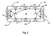
- the intermediate section of frame 3b has a rectangular section, having an area lower with respect to the section of soil excavated by drums 2 and having four lateral walls 7a-7d; in this way, all around the intermediate section of frame 3b there are empty spaces 100 which separate walls 110 of the excavation from lateral walls 7a-7d.
- sensors 4 are fixedly arranged upon one only plane of the intermediate section of frame 3b, in peripheral position and in such a way as to be equally spaced the one with respect to the other.
- sensors 4 In order to correctly detect the profile of the excavation, sensors 4 must be mounted on device 1 in such a way as to be directed towards two opposite walls 110 of the excavation and, preferably, directed towards the lateral walls of higher extension.
- sensors 4 are all directed towards the outside of frame 3, and are oriented in such a way as to carry out a measurement substantially in orthogonal direction with respect to the axis X and to the direction of maximum extension of frame 3.
- the measurement direction of sensors 4 cannot be purely orthogonal, because it is known that each sensor 4 has its own measurement beam width, that is it does not measure along a point direction but within a cone of small opening.
- Sensors 4 work on ultrasonic frequencies and permit to immediately verify, during the continuation of the excavation, the presence of out-of-shape profiles and, consequently, the danger of landslides without requiring the extraction of device 1 from the excavation.
- Each of sensors 4 measures the distance between wall 7a-7d upon which it is mounted and the corresponding wall of the excavation facing in the opposed position, by means of a measurement of the trip time (known with the term "round trip time").
- each sensor 4 sends repeated ultrasonic impulses against the respective excavation wall and measures the time used by that impulse to come back.
- the measurement of the distance between wall 7a-7d and the excavation wall is simply obtained by a multiplication between the time used and the propagation speed of the signal divided by two.
- Sensors 4 exchange data with a data processing unit 8, which permits to obtain in real time the shape of the excavation at the varying of the depth of penetration of device 1 and, together with other known sensors 9 installed on frame 3 of device 1 (gyroscopes, accelerometers, inclinometers) permits to detect also the shifting of the axis X of device 1 with respect to the theoretical excavation axis or the relative rotation of device 1 with respect to an external reference.
- sensors 9 installed on frame 3 of device 1 (gyroscopes, accelerometers, inclinometers) permits to detect also the shifting of the axis X of device 1 with respect to the theoretical excavation axis or the relative rotation of device 1 with respect to an external reference.
- sensors 4 can exchange data with data processing unit 8 or through a wired technique or via radio.
- a cable data transmission it will be necessary to provide for conductors sufficiently long in order to reach the surface (generally already present in these tool typologies); in the second case, that is when the data transmission among sensors 4 and data processing unit 8 is done via radio, it will be necessary to provide device 1 with one or more antennas for the data transmission, such as also data processing unit 8 must have a respective antenna for the reception.
- Data processing unit 8 is conveniently positioned in the frame of device 1 and transmits data on the surface for the real-time visualization and for their next storage.
- Data processing unit 8 is preferably inserted within a watertight box appropriately studied for the conditions of use during the creation of the excavations in the underground and sends signals using CAN technology towards the surface of the excavation itself by using only two cables of data transmission opportunely covered and shielded from the external agents.
- processing unit 8 already positioned on the frame in upper section 3c and necessary for the reception of the information deriving from the sensors on the excavation tool can be potentiated.
- data processing unit 8 is positioned outside of the excavation. In this case all the sensors installed on device 1 have to singularly transmit the data toward the surface of the excavation itself. For this reason the number of electrical conductors towards the surface increases both in number and in terms of the total required size.
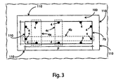
- data processing unit 8 carries out a data measurement procedure according to the measures of the distance detected by the couples of sensors 4 opposed the one with respect to the other.
- the shape and/or section of the excavation can be identified because the measures of the intermediate section of frame 3b is known and the distances among walls 7a-7d and the excavation walls are detected by the opposed couples of sensors 4.
- the measurement carried out by device 1 is important when operating in unstable lithologic conditions, where it can be real the danger of local landslides of the excavation walls (action of bulbs). In this case, in correspondence of the action of bulbs, the interested sensors detect an anomaly of empty space 100.
- the measures of couples 4a, 4b, 4c of the sensors are added to the measure of length I or depth p.
- the measures provided by it will be a part of the measurement of the depth of the excavation section; vice versa the second couple 4b of sensors 4 is oriented in the direction of depth; therefore the supplied measurements contribute to the measurement of the depth of the excavation section
- the length and the depth of the excavation section are directly calculated by data processing unit 8.
- the preceding data measurement procedure is repeated at predetermined time intervals by data processing unit 8; in this way, by repeating this procedure in times t1, t2, t3,... subsequent to t0 it is possible to obtain more measures of the excavation section s1, s2, ..., sn, by determining thus the profile of the excavation itself.
- the profile given by measures s1, s2, ...,sn of the excavation section is stored in data processing unit 8; through this storage it is possible to trace a discrete profile 20 of the excavation itself during the time, as shown in figure 5 and, through an integration process, it is possible to obtain also the volume of the excavated material, which can be then compared to a theoretical volume - calculated according to the size of the section detected by drums 2.
- profile 20 of the excavation will be more precise in terms of time and depth being the time instants t1, t2, ...,tn closer and - equally - the more precise in terms of section measure the more sensors 4 are mounted in higher number.
- a higher limit to the precision obtainable in measurements is also given by the intrinsic accuracy of sensors 4 and by the ratio among the size of the intermediate section of frame 3a and the number of sensors 4 here mounted.
- data processing unit 8 stores, for each section s1, s2, ..., sn of the excavation carried out, also the depth at which it has been obtained.
- section measures s1, s2, ..., sn can be set in function of the excavation depth or of the time passed from the preceding acquisition.
- device 1 removes material without moving forward and in this case it is important to correlate the measures to the excavation time.
- device 1 rapidly moves forward in the soil - on the contrary- it is important to carry out the measures in function of the depth (for example every 50 cm).
- the acquisition can be done also during the ascent of device 1 with the already shown methods, or by detecting the same sections measure during the advancement.
- data processing unit 8 provides for sending an alarm signal to a user who commands the drilling. In this way, it is possible to promptly actuate operations for the making safe of the excavation, with the increase of the density of the excavation mud for increasing the hydraulic load. On the other hand, in extreme cases the drilling can be interrupted and the excavation filled.
- data processing unit 8 processes the data deriving from each of sensors 4 in a distinct way and combines them with the data of traditional sensors 9, for permitting not only to detect the excavation section but also its positioning in the space; in this way it is possible to determine also the shifting of the axis of the excavation with respect to the axis X, that is therefore to determine if device 1 is rotating around itself or, even worse, is not vertically moving forward but transversally.
- this detection is carried out through a system provided with a gyroscopic sensor which detects the rotation of device 1 around axis X and which is generally combined with inclinometers which determine the angles along the axis lying on the transversal section.
- the system determines the lateral shifting along the other axis and this measure determines the shifting on the transversal plane of the advancement axis X of device 1 itself.
- corrections can be made, by actuating lateral guides 6 after having carried out the measures with accelerometers which are used for determining the shifting of the axis X due to lateral translations without inclinations of device 1.
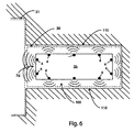
- Device 1 permits also to verify the effective superimposition of two diaphragm excavations the one adjacent to the other. As shown in figure 6 , in fact, if two excavations 30, 31 are adjacent, they are then limited, each one, only by three lateral walls 110. In this case, for verifying the effective superimposition of two excavations 30, 31, sensors 4 of one of lateral walls 7a-7d (in figure 6 , the sensors which face on wall 7d) have to find a distance higher than the others or, alternatively, show a cavity which extends outside of their range. Vice versa, if the two excavations 30, 31 begin to diverge the one with respect to the other, between them there would create again a wall of ground which would be detected by sensors 4 of wall 7d.
- sensors 4 are fixed upon a guide 4d slidingly engaged to frame 3 of device 1, able to slide from a first and a second operating position upon a plurality of guides 10 parallel among them and to the axis X. Therefore, sensors 4 which are fixed upon guide 4d in such a way as to detect - in their' complex - a direction orthogonal to axis X, vertically and autonomously slide on frame 3 and being engaged to guides 10, which offer an integral reference to the frame itself, cannot rotate or move axially with respect to it.
- the movement of guide 4d is carried out through an extensible jack 11, which is provided with a tool for the measurement of the position of guide 4d with respect to frame 3 of device 1; this tool is electrically connected to data processing unit 8 and permits to correctly identify the height at which guide 4d is positioned even if it slides with respect to the frame.
- This tool is high: in fact, without it, with the actuation of jack 11, it would be impossible to detect the correct depth at which the geometry and/or excavation section measurements are being made.
- jack 11 is able to move guide 4d from the lower end of upper ending section 3c of frame 3, near the intermediate section of frame 3b ( figure 7a ), along the whole vertical path ( figure 7b ) up to the reaching of an upper end stroke substantially in correspondence with an upper area of upper ending section 3c of frame 3.
- the presence of a rigid structure for the movement of sensors 4 is important because it permits to avoid the extraction of device 1 itself from the bottom of the excavation, if the probable presence of landslides during the continuation of the excavation itself is to be analyzed; device 1 remains then with excavation wheels 2 in contact with the bottom of the excavation itself, even without the stopping of excavation wheels 2, whereas the rigid structure is moved upwards and then again downwards. During this movement, the section and/or geometry of the excavation is again acquired as previously described.
- a third embodiment of the device object of the present invention is shown in figure 8a and in figure 8b .
- the third embodiment of device 1 differs from the second - previously described - for the means of actuation of the movement of guide 4d of the sensors; in this case, in fact, the means of actuation comprises a winch system.
- said system comprises an upper pulley 12 and a lower winch 13 upon which a traction cable 14 slides, constrained to guide 4d.
- upper pulley 12 is in the upper end of this section, whereas winch 13 is substantially in intermediate section 3b of frame 3.
- This embodiment permits to use the whole height of device 1 as useful stroke for guide 4d which holds the sensors, therefore ensures a better mounting covering of the profile of the excavation.
- the position of guide 4d with respect to frame 3 can be determined either with a rotation sensor (encoder) positioned in proximity either of pulley 12 or on the rotation axis of winch 13, or could be determined with a depth gauge which reads directly the stroke of guide 4d with respect to a reference point positioned on frame 3.
- a rotation sensor encoder
- a depth gauge which reads directly the stroke of guide 4d with respect to a reference point positioned on frame 3.
- a fourth embodiment of the present invention is shown in figure 9 ; in this case sensors 4 are mounted on a guide 4d vertically sliding in parallel with respect to axis X in such a way as to laterally detect the profile of the excavation.
- guides 10 are still present for the integral reference of guide 4d to frame 3 of device 1 for avoiding rotation and movements of sensors 4 with respect to frame 3.
- the detection of the profile of the excavation - made by sensors 4 - cannot be continuous, because sensors 4 are mounted in a back position with respect to lateral guides (flaps) 6. If the detection would be continuous, the measurement made during the movement of sensors 4 between the first and the second position of use would be distorted by the detection of the back profile of lateral guides 6.
- Lateral guides 6 do not uninterruptedly extend upon the whole lateral development along the axis X of device 1; on the contrary, they have a reduced length and are mounted in a number higher than one for each side of frame 3 (in figure 9 are shown three for each part). An interval of empty frame 21 is left between the one and the other lateral guide 6.
- the detection of the profile of the excavation is made with a spot mode, only in correspondence with the intervals of empty frame 21.
- This detection mode does not influence in a significantly negative way the functioning of device 1, as for their nature the landslides of an excavation vertically extend upon lengths very relevant with respect to the ones available for the spot reading. Therefore, by installing lateral guides 6 of comparable length, it is possible to carry out anyway a good scanning or detection of the profile of the excavation carried out.
- sensor block 4 only on one side of the device for simplicity of representation: in order to detect the geometry and the excavation section it is anyway necessary that a second guide 4a of sensors 4 is positioned on the opposite side, independently or integrally movable with the previous one.
- the measures of the section can anyhow be calculated considering as constant the measures of the distance from the walls on the two sides of the excavation not measured; in particular, in fact, it is opportune to consider possible problems of landslide mainly on the sides of the excavation with higher extension; a possible landslide upon one or both the sides of lower extension results less relevant in these cases (in particular when the ratio among the measures of the couples of opposite sides is strongly balanced upon one of the couples of sides, in some cases this ratio reaches values as 1:3 or 1:4) and anyway it would be partially detected by at least one of sensors 4 nearer to the angle among the walls of the device.
- device 1 permits the monitoring of the profile of the excavation of prismatic shape both during the continuation of the excavation and after it, thus evaluating possible differences in the measurements made which can be due to, for example, landslides.
- the after-excavation analysis of the prismatic section and of the profile of the excavation is particularly useful for diaphragms, because they, differently from the circular holes, cannot count on the stabilizing and unloading effect of the forces typical of the arch-shaped or circular walls.
- the monitoring of the stability of excavation walls 11 it is not anymore necessary to extract the drilling device and successively to introduce a different element of measure; the monitoring of the stability of walls 110 is wholly guaranteed without the complete extraction of device 1 which, however, can anyway begin again the monitoring of the walls even on different drilling times.
- device 1 permits to monitor also the effective superimposition of different diaphragm excavations, still through the measurement of the section of the excavation.
- block 5 for the uplifting and the lowering of device 1 can be replaced by a different uplifting means, able anyway to permit the same operations.
- openings on the lateral guides in such a way as to permit that the sensor can measure the distance from the wall passing through the opening made on the lateral guide. In this case it is possible to increase the number of holes for having smaller reading pitches during the measurement.
Landscapes
- Engineering & Computer Science (AREA)
- Mining & Mineral Resources (AREA)
- Structural Engineering (AREA)
- Life Sciences & Earth Sciences (AREA)
- General Engineering & Computer Science (AREA)
- Civil Engineering (AREA)
- Physics & Mathematics (AREA)
- Mechanical Engineering (AREA)
- General Life Sciences & Earth Sciences (AREA)
- Environmental & Geological Engineering (AREA)
- Geology (AREA)
- Fluid Mechanics (AREA)
- Electromagnetism (AREA)
- Geophysics (AREA)
- Paleontology (AREA)
- Agronomy & Crop Science (AREA)
- Geochemistry & Mineralogy (AREA)
- Soil Sciences (AREA)
- Analysing Materials By The Use Of Radiation (AREA)
- Testing Or Calibration Of Command Recording Devices (AREA)
- Earth Drilling (AREA)
Applications Claiming Priority (1)
| Application Number | Priority Date | Filing Date | Title |
|---|---|---|---|
| ITTO2009A000438A IT1394900B1 (it) | 2009-06-09 | 2009-06-09 | Dispositivo di scavo ed analisi del profilo dello scavo stesso e metodo associato. |
Publications (2)
| Publication Number | Publication Date |
|---|---|
| EP2273067A1 EP2273067A1 (en) | 2011-01-12 |
| EP2273067B1 true EP2273067B1 (en) | 2012-02-08 |
Family
ID=41478982
Family Applications (1)
| Application Number | Title | Priority Date | Filing Date |
|---|---|---|---|
| EP10162781A Not-in-force EP2273067B1 (en) | 2009-06-09 | 2010-05-13 | Excavation device and profile analysis of the excavation itself and associated method. |
Country Status (4)
| Country | Link |
|---|---|
| US (1) | US8065813B2 (it) |
| EP (1) | EP2273067B1 (it) |
| AT (1) | ATE544932T1 (it) |
| IT (1) | IT1394900B1 (it) |
Cited By (2)
| Publication number | Priority date | Publication date | Assignee | Title |
|---|---|---|---|---|
| DE102013008621A1 (de) * | 2013-05-21 | 2014-11-27 | Bauer Spezialtiefbau Gmbh | Vorrichtung und Verfahren zur überwachten Herstellung eines Hochdruckinjektionskörper |
| CN110243344A (zh) * | 2018-03-09 | 2019-09-17 | 索列丹斯-弗莱西奈公司 | 包括用于连接测量垂直度用装置的装置的钻机 |
Families Citing this family (10)
| Publication number | Priority date | Publication date | Assignee | Title |
|---|---|---|---|---|
| IT1394900B1 (it) * | 2009-06-09 | 2012-07-20 | Soilmec Spa | Dispositivo di scavo ed analisi del profilo dello scavo stesso e metodo associato. |
| KR101743294B1 (ko) * | 2010-11-01 | 2017-06-15 | 두산인프라코어 주식회사 | 건설장비의 모니터링 데이터 샘플링 방법 |
| CN103669448B (zh) * | 2012-09-12 | 2017-06-30 | 上海金泰工程机械有限公司 | 带圆弧摆动式切削装置的铣轮支架 |
| FR3001251B1 (fr) * | 2013-01-23 | 2017-05-26 | Soletanche Freyssinet | Procede de determination de la position d'un dispositif de coupe dans le sol a l'aide d'un chariot mobile |
| US10690805B2 (en) | 2013-12-05 | 2020-06-23 | Pile Dynamics, Inc. | Borehold testing device |
| AU2016307870B2 (en) | 2015-08-14 | 2020-04-23 | Pile Dynamics, Inc. | Borehole testing device |
| IT201700022210A1 (it) * | 2017-02-28 | 2018-08-28 | Soilmec Spa | Dispositivo di misura di uno scavo. |
| CN110567519B (zh) * | 2019-08-30 | 2024-04-09 | 中国地质大学(武汉) | 用于监测滑坡体深孔土体的压力、含水量的测量单元 |
| FR3107537B1 (fr) * | 2020-02-25 | 2022-04-08 | Soletanche Freyssinet | Machine d’excavation ayant un châssis muni d’ailes de guidage |
| CN116698494B (zh) * | 2023-07-19 | 2025-07-15 | 中国科学院东北地理与农业生态研究所 | 土壤采集设备 |
Family Cites Families (16)
| Publication number | Priority date | Publication date | Assignee | Title |
|---|---|---|---|---|
| US3882606A (en) * | 1973-05-16 | 1975-05-13 | Amf Inc | Method and apparatus for measuring curvature and curvature variations in pipelines and the like |
| US4228593A (en) * | 1978-05-05 | 1980-10-21 | Westinghouse Electric Corp. | Internal diameter measuring apparatus |
| US4722142A (en) * | 1982-12-10 | 1988-02-02 | Shell Oil Company | Coating thickness gauge |
| US4780962A (en) * | 1983-12-05 | 1988-11-01 | T. D. Williamson, Inc. | Pipeline bend verification pig |
| US5088336A (en) * | 1986-01-17 | 1992-02-18 | Tdw Delaware, Inc. | Pipeline caliper pig |
| US4953412A (en) * | 1986-01-17 | 1990-09-04 | T. D. Williamson, Inc. | Pipeline caliper pig |
| US4930223A (en) * | 1989-02-27 | 1990-06-05 | Tdw Delaware, Inc. | Bend detector pig |
| DE4119212C2 (de) * | 1991-06-11 | 1996-06-27 | Bauer Spezialtiefbau | Verfahren zum Fräsen einer Schlitzwand |
| US5205048A (en) * | 1991-11-20 | 1993-04-27 | Tdw Delaware, Inc. | Pipeline bend detector pig |
| JP2572932B2 (ja) * | 1993-06-03 | 1997-01-16 | 鹿島建設株式会社 | 掘削孔の内面形状測定方法及び装置 |
| JP3538685B2 (ja) * | 1994-01-31 | 2004-06-14 | 株式会社利根 | 掘削機の変位量計測装置 |
| JP2982890B2 (ja) * | 1994-10-03 | 1999-11-29 | 株式会社大林組 | 地盤掘削機の姿勢計測装置および姿勢制御方法 |
| JPH0989563A (ja) * | 1995-09-26 | 1997-04-04 | Sato Kogyo Co Ltd | 地下掘削機の位置検出方法及び装置 |
| GB0104838D0 (en) | 2001-02-27 | 2001-04-18 | Pathfinder Energy Services Ltd | Pathfinder |
| US6931748B2 (en) * | 2002-04-05 | 2005-08-23 | Varco I/P, Inc. | Riser and tubular inspection systems |
| IT1394900B1 (it) * | 2009-06-09 | 2012-07-20 | Soilmec Spa | Dispositivo di scavo ed analisi del profilo dello scavo stesso e metodo associato. |
-
2009
- 2009-06-09 IT ITTO2009A000438A patent/IT1394900B1/it active
-
2010
- 2010-05-13 AT AT10162781T patent/ATE544932T1/de active
- 2010-05-13 EP EP10162781A patent/EP2273067B1/en not_active Not-in-force
- 2010-06-09 US US12/797,303 patent/US8065813B2/en not_active Expired - Fee Related
Cited By (4)
| Publication number | Priority date | Publication date | Assignee | Title |
|---|---|---|---|---|
| DE102013008621A1 (de) * | 2013-05-21 | 2014-11-27 | Bauer Spezialtiefbau Gmbh | Vorrichtung und Verfahren zur überwachten Herstellung eines Hochdruckinjektionskörper |
| DE102013008621B4 (de) * | 2013-05-21 | 2016-08-04 | Bauer Spezialtiefbau Gmbh | Vorrichtung und Verfahren zur überwachten Herstellung eines Hochdruckinjektionskörper |
| CN110243344A (zh) * | 2018-03-09 | 2019-09-17 | 索列丹斯-弗莱西奈公司 | 包括用于连接测量垂直度用装置的装置的钻机 |
| CN110243344B (zh) * | 2018-03-09 | 2021-08-31 | 索列丹斯-弗莱西奈公司 | 包括用于连接测量垂直度用装置的装置的钻机 |
Also Published As
| Publication number | Publication date |
|---|---|
| EP2273067A1 (en) | 2011-01-12 |
| US20100307825A1 (en) | 2010-12-09 |
| ATE544932T1 (de) | 2012-02-15 |
| IT1394900B1 (it) | 2012-07-20 |
| US8065813B2 (en) | 2011-11-29 |
| ITTO20090438A1 (it) | 2010-12-10 |
Similar Documents
| Publication | Publication Date | Title |
|---|---|---|
| US8065813B2 (en) | Excavation device and profile analyses of the excavation itself and associated method | |
| KR101459063B1 (ko) | 트렌치 벽 요소를 생성하기 위한 방법 및 장치 | |
| US12000975B2 (en) | Borehole inspecting and testing device and method of using the same | |
| RU2667986C2 (ru) | Система и способ обнаружения разрушения гантельного замка скребкового конвейера | |
| GB2101742A (en) | Determining the position of a forwarding pipe or tunnel section | |
| US6781130B2 (en) | Geosteering of solid mineral mining machines | |
| HK1252035A1 (zh) | 钻孔测试装置 | |
| US20200332650A1 (en) | Apparatus and method for determining position of drilling tool during drilling | |
| JP2011202354A (ja) | トンネル切羽前方探査装置 | |
| US5934387A (en) | Method for determining the position of a tool of a rock drill | |
| CN112611316A (zh) | 一种井下围岩变形探测方法及装置 | |
| CN108267210A (zh) | 一种盾构机出土量测量及预警系统 | |
| CN114294061A (zh) | 一种采区矿压立体化监测方法 | |
| CN112432727B (zh) | 底板突水预警方法 | |
| AU2020202412B2 (en) | Apparatus and method for determining position of drilling tool during drilling | |
| JP6618541B2 (ja) | 地中の孔を計測する計測装置及び方法 | |
| KR100951811B1 (ko) | 슬라이딩 방식의 앵커를 장착한 지중변위 측정 장치 | |
| KR101837897B1 (ko) | 지반 상태 측정 디바이스 | |
| KR20170037036A (ko) | 표준관입시험기용 자동측정장치 | |
| KR101527203B1 (ko) | 관입 위치 측정 기반의 관입 시험 장치 | |
| CN121066180A (zh) | 一种超深防渗墙用预埋件垂直下设方法 | |
| CN109612423A (zh) | 基于位移传感器的巷道坍塌预测方法及系统 | |
| CN106948387A (zh) | 一种已运行桥梁桩基长度检测的方法及装置 | |
| CN211851810U (zh) | 一种自动猫道推车位置控制系统 | |
| JP2000292147A (ja) | 水平変位測定装置およびその設置方法 |
Legal Events
| Date | Code | Title | Description |
|---|---|---|---|
| PUAI | Public reference made under article 153(3) epc to a published international application that has entered the european phase |
Free format text: ORIGINAL CODE: 0009012 |
|
| AK | Designated contracting states |
Kind code of ref document: A1 Designated state(s): AL AT BE BG CH CY CZ DE DK EE ES FI FR GB GR HR HU IE IS IT LI LT LU LV MC MK MT NL NO PL PT RO SE SI SK SM TR |
|
| AX | Request for extension of the european patent |
Extension state: BA ME RS |
|
| 17P | Request for examination filed |
Effective date: 20110707 |
|
| GRAP | Despatch of communication of intention to grant a patent |
Free format text: ORIGINAL CODE: EPIDOSNIGR1 |
|
| RIC1 | Information provided on ipc code assigned before grant |
Ipc: E02F 3/20 20060101ALI20110830BHEP Ipc: E02F 3/26 20060101ALI20110830BHEP Ipc: E21B 47/08 20060101AFI20110830BHEP Ipc: E02D 3/12 20060101ALI20110830BHEP |
|
| GRAS | Grant fee paid |
Free format text: ORIGINAL CODE: EPIDOSNIGR3 |
|
| GRAA | (expected) grant |
Free format text: ORIGINAL CODE: 0009210 |
|
| AK | Designated contracting states |
Kind code of ref document: B1 Designated state(s): AL AT BE BG CH CY CZ DE DK EE ES FI FR GB GR HR HU IE IS IT LI LT LU LV MC MK MT NL NO PL PT RO SE SI SK SM TR |
|
| REG | Reference to a national code |
Ref country code: GB Ref legal event code: FG4D |
|
| REG | Reference to a national code |
Ref country code: AT Ref legal event code: REF Ref document number: 544932 Country of ref document: AT Kind code of ref document: T Effective date: 20120215 Ref country code: CH Ref legal event code: EP |
|
| REG | Reference to a national code |
Ref country code: DE Ref legal event code: R096 Ref document number: 602010000801 Country of ref document: DE Effective date: 20120405 |
|
| REG | Reference to a national code |
Ref country code: NL Ref legal event code: VDEP Effective date: 20120208 |
|
| LTIE | Lt: invalidation of european patent or patent extension |
Effective date: 20120208 |
|
| PG25 | Lapsed in a contracting state [announced via postgrant information from national office to epo] |
Ref country code: NL Free format text: LAPSE BECAUSE OF FAILURE TO SUBMIT A TRANSLATION OF THE DESCRIPTION OR TO PAY THE FEE WITHIN THE PRESCRIBED TIME-LIMIT Effective date: 20120208 Ref country code: NO Free format text: LAPSE BECAUSE OF FAILURE TO SUBMIT A TRANSLATION OF THE DESCRIPTION OR TO PAY THE FEE WITHIN THE PRESCRIBED TIME-LIMIT Effective date: 20120508 Ref country code: IS Free format text: LAPSE BECAUSE OF FAILURE TO SUBMIT A TRANSLATION OF THE DESCRIPTION OR TO PAY THE FEE WITHIN THE PRESCRIBED TIME-LIMIT Effective date: 20120608 Ref country code: LT Free format text: LAPSE BECAUSE OF FAILURE TO SUBMIT A TRANSLATION OF THE DESCRIPTION OR TO PAY THE FEE WITHIN THE PRESCRIBED TIME-LIMIT Effective date: 20120208 Ref country code: HR Free format text: LAPSE BECAUSE OF FAILURE TO SUBMIT A TRANSLATION OF THE DESCRIPTION OR TO PAY THE FEE WITHIN THE PRESCRIBED TIME-LIMIT Effective date: 20120208 |
|
| PG25 | Lapsed in a contracting state [announced via postgrant information from national office to epo] |
Ref country code: BE Free format text: LAPSE BECAUSE OF FAILURE TO SUBMIT A TRANSLATION OF THE DESCRIPTION OR TO PAY THE FEE WITHIN THE PRESCRIBED TIME-LIMIT Effective date: 20120208 Ref country code: GR Free format text: LAPSE BECAUSE OF FAILURE TO SUBMIT A TRANSLATION OF THE DESCRIPTION OR TO PAY THE FEE WITHIN THE PRESCRIBED TIME-LIMIT Effective date: 20120509 Ref country code: FI Free format text: LAPSE BECAUSE OF FAILURE TO SUBMIT A TRANSLATION OF THE DESCRIPTION OR TO PAY THE FEE WITHIN THE PRESCRIBED TIME-LIMIT Effective date: 20120208 Ref country code: PT Free format text: LAPSE BECAUSE OF FAILURE TO SUBMIT A TRANSLATION OF THE DESCRIPTION OR TO PAY THE FEE WITHIN THE PRESCRIBED TIME-LIMIT Effective date: 20120608 Ref country code: LV Free format text: LAPSE BECAUSE OF FAILURE TO SUBMIT A TRANSLATION OF THE DESCRIPTION OR TO PAY THE FEE WITHIN THE PRESCRIBED TIME-LIMIT Effective date: 20120208 Ref country code: PL Free format text: LAPSE BECAUSE OF FAILURE TO SUBMIT A TRANSLATION OF THE DESCRIPTION OR TO PAY THE FEE WITHIN THE PRESCRIBED TIME-LIMIT Effective date: 20120208 |
|
| REG | Reference to a national code |
Ref country code: AT Ref legal event code: MK05 Ref document number: 544932 Country of ref document: AT Kind code of ref document: T Effective date: 20120208 |
|
| PG25 | Lapsed in a contracting state [announced via postgrant information from national office to epo] |
Ref country code: CY Free format text: LAPSE BECAUSE OF FAILURE TO SUBMIT A TRANSLATION OF THE DESCRIPTION OR TO PAY THE FEE WITHIN THE PRESCRIBED TIME-LIMIT Effective date: 20120208 |
|
| PG25 | Lapsed in a contracting state [announced via postgrant information from national office to epo] |
Ref country code: EE Free format text: LAPSE BECAUSE OF FAILURE TO SUBMIT A TRANSLATION OF THE DESCRIPTION OR TO PAY THE FEE WITHIN THE PRESCRIBED TIME-LIMIT Effective date: 20120208 Ref country code: SE Free format text: LAPSE BECAUSE OF FAILURE TO SUBMIT A TRANSLATION OF THE DESCRIPTION OR TO PAY THE FEE WITHIN THE PRESCRIBED TIME-LIMIT Effective date: 20120208 Ref country code: DK Free format text: LAPSE BECAUSE OF FAILURE TO SUBMIT A TRANSLATION OF THE DESCRIPTION OR TO PAY THE FEE WITHIN THE PRESCRIBED TIME-LIMIT Effective date: 20120208 Ref country code: SI Free format text: LAPSE BECAUSE OF FAILURE TO SUBMIT A TRANSLATION OF THE DESCRIPTION OR TO PAY THE FEE WITHIN THE PRESCRIBED TIME-LIMIT Effective date: 20120208 Ref country code: CZ Free format text: LAPSE BECAUSE OF FAILURE TO SUBMIT A TRANSLATION OF THE DESCRIPTION OR TO PAY THE FEE WITHIN THE PRESCRIBED TIME-LIMIT Effective date: 20120208 Ref country code: RO Free format text: LAPSE BECAUSE OF FAILURE TO SUBMIT A TRANSLATION OF THE DESCRIPTION OR TO PAY THE FEE WITHIN THE PRESCRIBED TIME-LIMIT Effective date: 20120208 |
|
| PG25 | Lapsed in a contracting state [announced via postgrant information from national office to epo] |
Ref country code: SK Free format text: LAPSE BECAUSE OF FAILURE TO SUBMIT A TRANSLATION OF THE DESCRIPTION OR TO PAY THE FEE WITHIN THE PRESCRIBED TIME-LIMIT Effective date: 20120208 |
|
| PLBE | No opposition filed within time limit |
Free format text: ORIGINAL CODE: 0009261 |
|
| STAA | Information on the status of an ep patent application or granted ep patent |
Free format text: STATUS: NO OPPOSITION FILED WITHIN TIME LIMIT |
|
| PG25 | Lapsed in a contracting state [announced via postgrant information from national office to epo] |
Ref country code: MC Free format text: LAPSE BECAUSE OF NON-PAYMENT OF DUE FEES Effective date: 20120531 |
|
| 26N | No opposition filed |
Effective date: 20121109 |
|
| PG25 | Lapsed in a contracting state [announced via postgrant information from national office to epo] |
Ref country code: AT Free format text: LAPSE BECAUSE OF FAILURE TO SUBMIT A TRANSLATION OF THE DESCRIPTION OR TO PAY THE FEE WITHIN THE PRESCRIBED TIME-LIMIT Effective date: 20120208 |
|
| REG | Reference to a national code |
Ref country code: IE Ref legal event code: MM4A |
|
| PG25 | Lapsed in a contracting state [announced via postgrant information from national office to epo] |
Ref country code: MK Free format text: LAPSE BECAUSE OF FAILURE TO SUBMIT A TRANSLATION OF THE DESCRIPTION OR TO PAY THE FEE WITHIN THE PRESCRIBED TIME-LIMIT Effective date: 20120208 |
|
| REG | Reference to a national code |
Ref country code: DE Ref legal event code: R097 Ref document number: 602010000801 Country of ref document: DE Effective date: 20121109 |
|
| PG25 | Lapsed in a contracting state [announced via postgrant information from national office to epo] |
Ref country code: IE Free format text: LAPSE BECAUSE OF NON-PAYMENT OF DUE FEES Effective date: 20120513 Ref country code: ES Free format text: LAPSE BECAUSE OF FAILURE TO SUBMIT A TRANSLATION OF THE DESCRIPTION OR TO PAY THE FEE WITHIN THE PRESCRIBED TIME-LIMIT Effective date: 20120519 |
|
| PG25 | Lapsed in a contracting state [announced via postgrant information from national office to epo] |
Ref country code: BG Free format text: LAPSE BECAUSE OF FAILURE TO SUBMIT A TRANSLATION OF THE DESCRIPTION OR TO PAY THE FEE WITHIN THE PRESCRIBED TIME-LIMIT Effective date: 20120508 Ref country code: MT Free format text: LAPSE BECAUSE OF FAILURE TO SUBMIT A TRANSLATION OF THE DESCRIPTION OR TO PAY THE FEE WITHIN THE PRESCRIBED TIME-LIMIT Effective date: 20120208 |
|
| PG25 | Lapsed in a contracting state [announced via postgrant information from national office to epo] |
Ref country code: AL Free format text: LAPSE BECAUSE OF FAILURE TO SUBMIT A TRANSLATION OF THE DESCRIPTION OR TO PAY THE FEE WITHIN THE PRESCRIBED TIME-LIMIT Effective date: 20120208 |
|
| PG25 | Lapsed in a contracting state [announced via postgrant information from national office to epo] |
Ref country code: TR Free format text: LAPSE BECAUSE OF FAILURE TO SUBMIT A TRANSLATION OF THE DESCRIPTION OR TO PAY THE FEE WITHIN THE PRESCRIBED TIME-LIMIT Effective date: 20120208 |
|
| PG25 | Lapsed in a contracting state [announced via postgrant information from national office to epo] |
Ref country code: SM Free format text: LAPSE BECAUSE OF FAILURE TO SUBMIT A TRANSLATION OF THE DESCRIPTION OR TO PAY THE FEE WITHIN THE PRESCRIBED TIME-LIMIT Effective date: 20120208 Ref country code: LU Free format text: LAPSE BECAUSE OF NON-PAYMENT OF DUE FEES Effective date: 20120513 |
|
| PG25 | Lapsed in a contracting state [announced via postgrant information from national office to epo] |
Ref country code: HU Free format text: LAPSE BECAUSE OF FAILURE TO SUBMIT A TRANSLATION OF THE DESCRIPTION OR TO PAY THE FEE WITHIN THE PRESCRIBED TIME-LIMIT Effective date: 20100513 |
|
| REG | Reference to a national code |
Ref country code: CH Ref legal event code: PL |
|
| GBPC | Gb: european patent ceased through non-payment of renewal fee |
Effective date: 20140513 |
|
| PG25 | Lapsed in a contracting state [announced via postgrant information from national office to epo] |
Ref country code: CH Free format text: LAPSE BECAUSE OF NON-PAYMENT OF DUE FEES Effective date: 20140531 Ref country code: LI Free format text: LAPSE BECAUSE OF NON-PAYMENT OF DUE FEES Effective date: 20140531 |
|
| PG25 | Lapsed in a contracting state [announced via postgrant information from national office to epo] |
Ref country code: GB Free format text: LAPSE BECAUSE OF NON-PAYMENT OF DUE FEES Effective date: 20140513 |
|
| REG | Reference to a national code |
Ref country code: FR Ref legal event code: PLFP Year of fee payment: 7 |
|
| REG | Reference to a national code |
Ref country code: FR Ref legal event code: PLFP Year of fee payment: 8 |
|
| REG | Reference to a national code |
Ref country code: FR Ref legal event code: PLFP Year of fee payment: 9 |
|
| PGFP | Annual fee paid to national office [announced via postgrant information from national office to epo] |
Ref country code: DE Payment date: 20180502 Year of fee payment: 9 |
|
| PGFP | Annual fee paid to national office [announced via postgrant information from national office to epo] |
Ref country code: IT Payment date: 20180522 Year of fee payment: 9 Ref country code: FR Payment date: 20180411 Year of fee payment: 9 |
|
| REG | Reference to a national code |
Ref country code: DE Ref legal event code: R119 Ref document number: 602010000801 Country of ref document: DE |
|
| PG25 | Lapsed in a contracting state [announced via postgrant information from national office to epo] |
Ref country code: DE Free format text: LAPSE BECAUSE OF NON-PAYMENT OF DUE FEES Effective date: 20191203 Ref country code: IT Free format text: LAPSE BECAUSE OF NON-PAYMENT OF DUE FEES Effective date: 20190513 |
|
| PG25 | Lapsed in a contracting state [announced via postgrant information from national office to epo] |
Ref country code: FR Free format text: LAPSE BECAUSE OF NON-PAYMENT OF DUE FEES Effective date: 20190531 |