EP2272798A2 - Process for making titanium dioxide - Google Patents
Process for making titanium dioxide Download PDFInfo
- Publication number
- EP2272798A2 EP2272798A2 EP10013090A EP10013090A EP2272798A2 EP 2272798 A2 EP2272798 A2 EP 2272798A2 EP 10013090 A EP10013090 A EP 10013090A EP 10013090 A EP10013090 A EP 10013090A EP 2272798 A2 EP2272798 A2 EP 2272798A2
- Authority
- EP
- European Patent Office
- Prior art keywords
- tail gas
- analyzer
- oxygen
- line
- titanium dioxide
- Prior art date
- Legal status (The legal status is an assumption and is not a legal conclusion. Google has not performed a legal analysis and makes no representation as to the accuracy of the status listed.)
- Granted
Links
- GWEVSGVZZGPLCZ-UHFFFAOYSA-N Titan oxide Chemical compound O=[Ti]=O GWEVSGVZZGPLCZ-UHFFFAOYSA-N 0.000 title claims abstract description 95
- 239000004408 titanium dioxide Substances 0.000 title claims abstract description 47
- 238000000034 method Methods 0.000 title claims abstract description 44
- 239000007789 gas Substances 0.000 claims abstract description 128
- ZAMOUSCENKQFHK-UHFFFAOYSA-N Chlorine atom Chemical compound [Cl] ZAMOUSCENKQFHK-UHFFFAOYSA-N 0.000 claims abstract description 52
- 239000000460 chlorine Substances 0.000 claims abstract description 52
- 229910052801 chlorine Inorganic materials 0.000 claims abstract description 51
- QVGXLLKOCUKJST-UHFFFAOYSA-N atomic oxygen Chemical compound [O] QVGXLLKOCUKJST-UHFFFAOYSA-N 0.000 claims abstract description 48
- 239000001301 oxygen Substances 0.000 claims abstract description 48
- 229910052760 oxygen Inorganic materials 0.000 claims abstract description 48
- XJDNKRIXUMDJCW-UHFFFAOYSA-J titanium tetrachloride Chemical compound Cl[Ti](Cl)(Cl)Cl XJDNKRIXUMDJCW-UHFFFAOYSA-J 0.000 claims abstract description 37
- 239000002245 particle Substances 0.000 claims abstract description 20
- 230000008016 vaporization Effects 0.000 claims abstract description 6
- 229910000041 hydrogen chloride Inorganic materials 0.000 claims description 26
- IXCSERBJSXMMFS-UHFFFAOYSA-N hydrogen chloride Substances Cl.Cl IXCSERBJSXMMFS-UHFFFAOYSA-N 0.000 claims description 26
- VEXZGXHMUGYJMC-UHFFFAOYSA-N Hydrochloric acid Chemical compound Cl VEXZGXHMUGYJMC-UHFFFAOYSA-N 0.000 claims description 25
- 230000003750 conditioning effect Effects 0.000 claims description 14
- 230000001143 conditioned effect Effects 0.000 claims description 12
- VEXZGXHMUGYJMC-UHFFFAOYSA-M Chloride anion Chemical compound [Cl-] VEXZGXHMUGYJMC-UHFFFAOYSA-M 0.000 claims description 11
- 239000011491 glass wool Substances 0.000 claims description 11
- 239000000126 substance Substances 0.000 claims description 6
- 230000005298 paramagnetic effect Effects 0.000 claims description 3
- IJGRMHOSHXDMSA-UHFFFAOYSA-N Atomic nitrogen Chemical compound N#N IJGRMHOSHXDMSA-UHFFFAOYSA-N 0.000 description 24
- 238000004458 analytical method Methods 0.000 description 14
- 229910052757 nitrogen Inorganic materials 0.000 description 12
- 238000010926 purge Methods 0.000 description 12
- 230000000052 comparative effect Effects 0.000 description 10
- 229920001774 Perfluoroether Polymers 0.000 description 9
- 238000005070 sampling Methods 0.000 description 6
- CURLTUGMZLYLDI-UHFFFAOYSA-N Carbon dioxide Chemical compound O=C=O CURLTUGMZLYLDI-UHFFFAOYSA-N 0.000 description 4
- 239000011152 fibreglass Substances 0.000 description 4
- 239000010802 sludge Substances 0.000 description 4
- UGFAIRIUMAVXCW-UHFFFAOYSA-N Carbon monoxide Chemical compound [O+]#[C-] UGFAIRIUMAVXCW-UHFFFAOYSA-N 0.000 description 3
- 229910002091 carbon monoxide Inorganic materials 0.000 description 3
- 239000007787 solid Substances 0.000 description 3
- OKTJSMMVPCPJKN-UHFFFAOYSA-N Carbon Chemical compound [C] OKTJSMMVPCPJKN-UHFFFAOYSA-N 0.000 description 2
- KZBUYRJDOAKODT-UHFFFAOYSA-N Chlorine Chemical compound ClCl KZBUYRJDOAKODT-UHFFFAOYSA-N 0.000 description 2
- ATUOYWHBWRKTHZ-UHFFFAOYSA-N Propane Chemical compound CCC ATUOYWHBWRKTHZ-UHFFFAOYSA-N 0.000 description 2
- 230000015572 biosynthetic process Effects 0.000 description 2
- 229910052799 carbon Inorganic materials 0.000 description 2
- 229910002092 carbon dioxide Inorganic materials 0.000 description 2
- 239000001569 carbon dioxide Substances 0.000 description 2
- 239000000428 dust Substances 0.000 description 2
- 238000001914 filtration Methods 0.000 description 2
- 239000000446 fuel Substances 0.000 description 2
- 239000012535 impurity Substances 0.000 description 2
- 239000000049 pigment Substances 0.000 description 2
- 238000004886 process control Methods 0.000 description 2
- RZVAJINKPMORJF-UHFFFAOYSA-N Acetaminophen Chemical compound CC(=O)NC1=CC=C(O)C=C1 RZVAJINKPMORJF-UHFFFAOYSA-N 0.000 description 1
- 239000000443 aerosol Substances 0.000 description 1
- 239000011230 binding agent Substances 0.000 description 1
- 239000005388 borosilicate glass Substances 0.000 description 1
- NHYCGSASNAIGLD-UHFFFAOYSA-N chlorine monoxide Inorganic materials Cl[O] NHYCGSASNAIGLD-UHFFFAOYSA-N 0.000 description 1
- 239000000571 coke Substances 0.000 description 1
- 238000009833 condensation Methods 0.000 description 1
- 230000005494 condensation Effects 0.000 description 1
- 230000008021 deposition Effects 0.000 description 1
- 238000010586 diagram Methods 0.000 description 1
- 229910001873 dinitrogen Inorganic materials 0.000 description 1
- 238000004821 distillation Methods 0.000 description 1
- 238000005516 engineering process Methods 0.000 description 1
- 239000000835 fiber Substances 0.000 description 1
- NBVXSUQYWXRMNV-UHFFFAOYSA-N fluoromethane Chemical compound FC NBVXSUQYWXRMNV-UHFFFAOYSA-N 0.000 description 1
- 239000011521 glass Substances 0.000 description 1
- 238000010438 heat treatment Methods 0.000 description 1
- 238000005259 measurement Methods 0.000 description 1
- 150000002829 nitrogen Chemical class 0.000 description 1
- 239000003973 paint Substances 0.000 description 1
- 238000005375 photometry Methods 0.000 description 1
- 239000001294 propane Substances 0.000 description 1
- 239000005297 pyrex Substances 0.000 description 1
- 238000004381 surface treatment Methods 0.000 description 1
- 238000004448 titration Methods 0.000 description 1
Images

Classifications
-
- C—CHEMISTRY; METALLURGY
- C01—INORGANIC CHEMISTRY
- C01G—COMPOUNDS CONTAINING METALS NOT COVERED BY SUBCLASSES C01D OR C01F
- C01G23/00—Compounds of titanium
- C01G23/04—Oxides; Hydroxides
- C01G23/047—Titanium dioxide
- C01G23/07—Producing by vapour phase processes, e.g. halide oxidation
-
- C—CHEMISTRY; METALLURGY
- C01—INORGANIC CHEMISTRY
- C01G—COMPOUNDS CONTAINING METALS NOT COVERED BY SUBCLASSES C01D OR C01F
- C01G23/00—Compounds of titanium
- C01G23/04—Oxides; Hydroxides
- C01G23/047—Titanium dioxide
-
- C—CHEMISTRY; METALLURGY
- C22—METALLURGY; FERROUS OR NON-FERROUS ALLOYS; TREATMENT OF ALLOYS OR NON-FERROUS METALS
- C22B—PRODUCTION AND REFINING OF METALS; PRETREATMENT OF RAW MATERIALS
- C22B34/00—Obtaining refractory metals
- C22B34/10—Obtaining titanium, zirconium or hafnium
- C22B34/12—Obtaining titanium or titanium compounds from ores or scrap by metallurgical processing; preparation of titanium compounds from other titanium compounds see C01G23/00 - C01G23/08
- C22B34/1218—Obtaining titanium or titanium compounds from ores or scrap by metallurgical processing; preparation of titanium compounds from other titanium compounds see C01G23/00 - C01G23/08 obtaining titanium or titanium compounds from ores or scrap by dry processes
- C22B34/1222—Obtaining titanium or titanium compounds from ores or scrap by metallurgical processing; preparation of titanium compounds from other titanium compounds see C01G23/00 - C01G23/08 obtaining titanium or titanium compounds from ores or scrap by dry processes using a halogen containing agent
-
- C—CHEMISTRY; METALLURGY
- C22—METALLURGY; FERROUS OR NON-FERROUS ALLOYS; TREATMENT OF ALLOYS OR NON-FERROUS METALS
- C22B—PRODUCTION AND REFINING OF METALS; PRETREATMENT OF RAW MATERIALS
- C22B34/00—Obtaining refractory metals
- C22B34/10—Obtaining titanium, zirconium or hafnium
- C22B34/12—Obtaining titanium or titanium compounds from ores or scrap by metallurgical processing; preparation of titanium compounds from other titanium compounds see C01G23/00 - C01G23/08
- C22B34/1218—Obtaining titanium or titanium compounds from ores or scrap by metallurgical processing; preparation of titanium compounds from other titanium compounds see C01G23/00 - C01G23/08 obtaining titanium or titanium compounds from ores or scrap by dry processes
- C22B34/1227—Obtaining titanium or titanium compounds from ores or scrap by metallurgical processing; preparation of titanium compounds from other titanium compounds see C01G23/00 - C01G23/08 obtaining titanium or titanium compounds from ores or scrap by dry processes using an oxygen containing agent
-
- C—CHEMISTRY; METALLURGY
- C22—METALLURGY; FERROUS OR NON-FERROUS ALLOYS; TREATMENT OF ALLOYS OR NON-FERROUS METALS
- C22B—PRODUCTION AND REFINING OF METALS; PRETREATMENT OF RAW MATERIALS
- C22B34/00—Obtaining refractory metals
- C22B34/10—Obtaining titanium, zirconium or hafnium
- C22B34/12—Obtaining titanium or titanium compounds from ores or scrap by metallurgical processing; preparation of titanium compounds from other titanium compounds see C01G23/00 - C01G23/08
- C22B34/1218—Obtaining titanium or titanium compounds from ores or scrap by metallurgical processing; preparation of titanium compounds from other titanium compounds see C01G23/00 - C01G23/08 obtaining titanium or titanium compounds from ores or scrap by dry processes
- C22B34/1231—Obtaining titanium or titanium compounds from ores or scrap by metallurgical processing; preparation of titanium compounds from other titanium compounds see C01G23/00 - C01G23/08 obtaining titanium or titanium compounds from ores or scrap by dry processes treatment or purification of titanium containing products obtained by dry processes, e.g. condensation
-
- G—PHYSICS
- G01—MEASURING; TESTING
- G01N—INVESTIGATING OR ANALYSING MATERIALS BY DETERMINING THEIR CHEMICAL OR PHYSICAL PROPERTIES
- G01N21/00—Investigating or analysing materials by the use of optical means, i.e. using sub-millimetre waves, infrared, visible or ultraviolet light
- G01N21/17—Systems in which incident light is modified in accordance with the properties of the material investigated
- G01N21/25—Colour; Spectral properties, i.e. comparison of effect of material on the light at two or more different wavelengths or wavelength bands
- G01N21/31—Investigating relative effect of material at wavelengths characteristic of specific elements or molecules, e.g. atomic absorption spectrometry
- G01N21/33—Investigating relative effect of material at wavelengths characteristic of specific elements or molecules, e.g. atomic absorption spectrometry using ultraviolet light
-
- G—PHYSICS
- G01—MEASURING; TESTING
- G01N—INVESTIGATING OR ANALYSING MATERIALS BY DETERMINING THEIR CHEMICAL OR PHYSICAL PROPERTIES
- G01N21/00—Investigating or analysing materials by the use of optical means, i.e. using sub-millimetre waves, infrared, visible or ultraviolet light
- G01N21/17—Systems in which incident light is modified in accordance with the properties of the material investigated
- G01N21/25—Colour; Spectral properties, i.e. comparison of effect of material on the light at two or more different wavelengths or wavelength bands
- G01N21/31—Investigating relative effect of material at wavelengths characteristic of specific elements or molecules, e.g. atomic absorption spectrometry
- G01N21/35—Investigating relative effect of material at wavelengths characteristic of specific elements or molecules, e.g. atomic absorption spectrometry using infrared light
- G01N21/3504—Investigating relative effect of material at wavelengths characteristic of specific elements or molecules, e.g. atomic absorption spectrometry using infrared light for analysing gases, e.g. multi-gas analysis
-
- Y—GENERAL TAGGING OF NEW TECHNOLOGICAL DEVELOPMENTS; GENERAL TAGGING OF CROSS-SECTIONAL TECHNOLOGIES SPANNING OVER SEVERAL SECTIONS OF THE IPC; TECHNICAL SUBJECTS COVERED BY FORMER USPC CROSS-REFERENCE ART COLLECTIONS [XRACs] AND DIGESTS
- Y02—TECHNOLOGIES OR APPLICATIONS FOR MITIGATION OR ADAPTATION AGAINST CLIMATE CHANGE
- Y02P—CLIMATE CHANGE MITIGATION TECHNOLOGIES IN THE PRODUCTION OR PROCESSING OF GOODS
- Y02P10/00—Technologies related to metal processing
- Y02P10/20—Recycling
Definitions
- a source of crude titanium dioxide (for example, rutile ore) from hopper 11 is first reacted with chlorine from chlorine tank 12 and carbon (for example, coke) from carbon hopper 13 in a chlorinator 14 to produce a gaseous stream 15 containing primarily titanium tetrachloride, carbon monoxide and carbon dioxide but also dust particles and other impurities.
- the titanium tetrachloride is condensed from stream 15 by condenser 16, purified by distillation, vaporized and then directed to burner 17 where the titanium tetrachloride is reacted with oxygen from oxygen tank 18 to produce a gaseous stream 19 containing primarily particulate titanium dioxide and chlorine gas.
- a support fuel such as propane gas
- propane gas can also be introduced into the burner 17 to increase the temperature in the burner 17.
- the stream 19 is then cooled in cooler 20 and then the particulate titanium dioxide is separated from the chlorine gas by gas/solids separator 21.
- the particulate titanium dioxide is then directed from gas/solids separator 21 to surface treatment tank 22 for further processing.
- the gaseous chlorine stream 25 from the gas/solids separator 21 is directed to a chlorine compressor 26 for recycle to the chlorinator 14.
- the gaseous chlorine stream 25 is commonly called "burner tail gas".
- the carbon monoxide, carbon dioxide, dust and other impurities from the condenser 16, commonly referred to as "chlorinator tail gas" 23 is treated by treatment system 24 to remove undesirable components (such as residual chlorine and carbon monoxide) and then vented.
- the particulate titanium dioxide produced by the chloride process is used, for example, as a pigment in paints.
- a more detailed discussion of the chloride process for producing titanium dioxide can be found in Volume 24 of the Kirk-Othmer Encyclopedia of Chemical Technology (4th Ed., 1997 ) and in Volume I of the Pigment Handbook, Edited by Lexis (2nd Ed., 1988 ).
- chemical analysis of the chlorinator tail gas 23 for residual chlorine allows for more effective control of the chlorinator 14.
- the chlorinator tail gas 23 will contain relatively high levels of chlorine to be treated by treatment system 24. Consequently, in conventional practice samples of the chlorinator tail gas are periodically taken to a laboratory and analyzed for chlorine to better control the chlorinator 14.
- chemical analysis of the burner tail gas 25 for oxygen allows for more effective control of the burner 17. For example, if an excessive amount of oxygen is fed to the burner 17, the excessive oxygen is wasted. Samples of the burner tail gas 25 are for this reason also commonly taken to a laboratory and analyzed for oxygen.
- the burner tail gas 25 can also be analyzed for hydrogen chloride since the hydrogen chloride concentration of the burner tail gas 25 is a function of the amount of support fuel used in the burner 17. Frequent sampling and analysis of the chlorinator tail gas 23 and the burner tail gas 25 are desired for close control of the chlorinator 14 and the burner 17. However, manual sampling and analysis of the chlorinator tail gas 23 and the burner tail gas 25 is labor intensive, relatively expensive and limits process control.
- the instant invention provides an effective solution to the above discussed problems.
- the chlorinator tail gas and/or the burner tail gas are analyzed on-line, thereby providing continuous automated analysis for better process control, with reduced labor requirements and expense associated with sampling and analysis.
- the instant invention provides an improved process for producing titanium dioxide by reacting a titanium dioxide ore with chlorine to produce a gaseous stream containing titanium tetrachloride, condensing titanium tetrachloride from the gaseous stream containing titanium tetrachloride to produce chlorinator tail gas, vaporizing the condensed titanium tetrachloride, reacting the vaporized titanium tetrachloride with oxygen to produce a gaseous stream containing titanium dioxide particles and chlorine, separating the titanium dioxide particles from the gaseous stream containing titanium dioxide particles and chlorine to produce burner tail gas, and analyzing the chlorinator tail gas for residual chlorine to control the step of reacting the titanium dioxide ore with chlorine,characterized in that the chlorinator tail gas is analyzed for residual chlorine using an on-line chlorine analyzer.
- the instant invention provides an improved process for producing titanium dioxide by reacting a titanium dioxide ore with chlorine to produce a gaseous stream containing titanium tetrachloride, condensing titanium tetrachloride from the gaseous stream containing titanium tetrachloride to produce chlorinator tail gas, vaporizing the condensed titanium tetrachloride, reacting the vaporized titanium tetrachloride with oxygen to produce a gaseous stream containing titanium dioxide particles and chlorine, separating the titanium dioxide particles from the gaseous stream containing titanium dioxide particles and chlorine to produce burner tail gas, and analyzing the burner tail gas for oxygen to control the step of reacting the vaporized titanium tetrachloride with oxygen, characterized in that the burner tail gas is analyzed for residual oxygen using an on-line oxygen analyzer.
- the instant invention provides a process for conditioning chlorinator tail gas or burner tail gas from a chloride process for making titanium dioxide.
- Components such as particulates and sludge
- This conditioning process includes three steps. The first step is to flow chlorinator tail gas or burner tail gas from a chloride process for making titanium dioxide through a bed of glass wool to produce a primary treated stream.
- the second step is to flow the primary treated stream through a submicron particulate filter to produce a secondary treated stream.
- the third step is to flow the secondary treated stream through a coalescing filter to produce a conditioned gas stream to be directed to an on-line chemical analyzer(s).
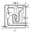
- an apparatus 30 for conditioning chlorinator tail gas or burner tail gas from a chloride process for making titanium dioxide.
- the apparatus 30 includes an enclosure 31.(preferably being a NEMA-4 fiberglass enclosure, Hoffman Co., Anoka, Minnesota USA) heated by a thermostated (at one hundred degrees Fahrenheit (38 degrees Celsius)) four hundred watt electric heater 32 (Hoffman Co.). Chlorinator tail gas or burner tail gas is conducted to the apparatus 30 by way of tubing 33 (preferably 0.375 inch (1 cm) outside diameter, 0.060 inch (0.015 cm) wall thickness, heat traced (at about ninety degrees Celsius) perfluoroalkoxy tubing) .
- tubing 33 preferably 0.375 inch (1 cm) outside diameter, 0.060 inch (0.015 cm) wall thickness, heat traced (at about ninety degrees Celsius) perfluoroalkoxy tubing
- the chlorinator tail gas or burner tail gas is then conducted to a one and one half inch (3.8 cm) diameter by fifteen inch (38 cm) long glass column 34 (part number 5820-53 & 5844-78, Ace Glass Co., Vineland, New Jersey USA) by one quarter inch (0.6 cm) diameter perfluoroalkoxy tubing 35 (part number U-06375-75, Cole Parmer, Vernon Hills, Illinois USA).
- the column 34 is packed with glass wool 36 (preferably, Pyrex Brand glass wool, product number Z25,589-0 from Sigma Aldrich, St. Louis, Missouri USA).
- the chlorinator tail gas or burner tail gas flows through the glass wool 36 to produce a primary treated stream conducted to a submicron filter 37 by way of one quarter inch (0.6 cm) diameter perfluoroalkoxy tubing 38.
- the glass wool 36 removes the larger particulates from the chlorinator tail gas or burner tail gas stream and provides a high surface area for deposition of sludge.
- the submicron filter 37 is a filter that removes particles from the primary treated stream that are smaller than one micron in size (preferably a United Filtration System, Sterling Heights, Michigan USA, borosilicate glass fiber/fluorocarbon binder submicron filter) to produce a secondary treated stream conducted to a coalescing filter 38 by way of one quarter inch (0.6 cm) diameter perfluoroalkoxy tubing 39.
- the secondary treated stream flows through the coalescing filter 38 (preferably a Genie Brand coalescing filter from A+ Corporation of Prairieville, Louisiana USA) to produce a conditioned gas stream that is flowed to a rotameter 40, through metering valve 43, by way of one quarter inch (0.6 cm) diameter perfluoroalkoxy tubing 41.
- the coalescing filter 38 removes aerosol mists that passed through the glass wool 36 and the submicron filter 37.
- the rotameter 40 (preferably part number U-03216-75 from Cole Parmer, Vernon Hills, Illinois USA) is used to measure the flow rate of the conditioned gas stream. A substantial reduction of the flow rate of the conditioned gas stream probably indicates that the glass wool 36 needs to be replaced (or possibly that the submicron filter 37 needs to be replaced).
- the conditioned gas stream is conducted to an on-line analyzer by way of heat traced (at about ninety degrees Celsius) one quarter inch (0.6 cm) diameter perfluoroalkoxy tubing 42.
- Tubing 44 is used to conduct a nitrogen purge stream into the enclosure 31.
- Tubing 45 is used to conduct the nitrogen purge stream from the enclosure 31.
- the heater 32 is most preferably set to control the temperature in the enclosure 31 to be preferably greater than fifty degrees Fahrenheit (10 degrees Celsius).
- the temperature in the enclosure 31 is set to be more than seventy degrees Fahrenheit (21 degrees Celsius).
- the temperature in the enclosure 31 is set to be in the range of from ninety to one hundred and ten degrees Fahrenheit (32 to 43 degrees Celsius). Heating the enclosure 31 (and thus the conditioning process of the instant invention) helps prevent the formation of sludge and significantly increases the service life of the conditioning system (and, of course, the on-line analyzers) and the need to replace plugged tubing and filters.
- the apparatus 30 can also include a differential pressure transducer(s) (not shown) to measure the pressure drop across the column 34, the submicron filter 37 and/or the coalescing filter 38 to better determine if the column 34, the submicron filter 37 or the coalescing filter 38 are becoming plugged and need replacement.
- a tubing tee and shut-off valve (not shown) are installed in the tubing 35 so that the flow of chlorinator tail gas or burner tail gas can be temporarily shut off so that nitrogen gas can be flowed through the apparatus 30 at a calibrated flow rate.
- a pressure transducer (not shown) can be installed to measure the pressure in the tubing 41. If the conditioned gas stream is to be directed to more than one on-line analyzer, then the conditioned gas stream can be split and a rotameter (or other flow measuring device or no such device or devices if desired) used for each such on-line analyzer.
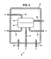
- the apparatus 50 includes an enclosure 51 (preferably a NEMA-4 fiberglass enclosure, supra).
- Tubing 52 is used to conduct a nitrogen purge stream into the enclosure 51.
- Tubing 53 is used to conduct the nitrogen purge stream from the enclosure 51.
- the enclosure 51 contains a Siemens Oxymat 6F-O 2 paramagnetic oxygen analyzer comprised of an electronics portion 54 and a cell portion 55.
- Tubing 56 is used to conduct a nitrogen purge stream into the electronics portion 54. This nitrogen purge stream then flows through the cell portion 55 and out of the enclosure 51 by way of tubing 57.
- Electrical cable 58 provides power to the electronics portion 54 as well as conducting an analyzer signal from the apparatus 50, which signal is a function of the oxygen concentration in the burner tail gas.
- Conditioned burner tail gas (from the apparatus shown in Fig. 2 ) is conducted to and from the cell portion 55 by way of one quarter inch (0.6 cm) diameter heat traced (at about ninety degrees Celsius) perfluoroalkoxy tubing 59 and 60 respectively.
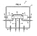
- FIG. 4 a side view, part in full, part in cross section and part schematic, is shown of an apparatus 70 for on-line analysis of burner tail gas for hydrogen chloride
- the apparatus 70 includes an enclosure 71 (preferably a NEMA-4 fiberglass enclosure).
- Tubing 72 is used to conduct a nitrogen purge stream into the enclosure 71.
- Tubing 73 is used to conduct the nitrogen purge stream from the enclosure 71.
- the enclosure 71 contains a Servomex Xendos 2500 HCl infrared analyzer (Servomex Company Inc., Sugarland, Texas USA) comprised of a detector portion 74, a cell portion 75 and a source portion 76.
- Tubing 77 is used to conduct a nitrogen purge stream through a boss 75a, then through boss 75b by way of tubing 77a and then out of the enclosure 71 by way of tubing 78.
- the boss portions 75a and 75b of the cell 75 help protect the detector portion 74 and the source portion 76 from leaks.
- Electrical cables 79 and 80 provide power to and conduct an analyzer signal from the apparatus 70, which signal is a function of the hydrogen chloride concentration in the burner tail gas.
- Conditioned burner tail gas (from the apparatus shown in Fig. 2 ) is conducted to and from the cell portion 75 by way of one quarter inch (0.6 cm) diameter heat traced (at about ninety degrees Celsius) perfluoroalkoxy tubing 81 and 82 respectively.
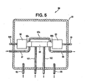
- the apparatus 90 includes an enclosure 91 (preferably a NEMA-4 fiberglass enclosure).
- Tubing 92 is used to conduct a nitrogen purge stream into the enclosure 91.
- Tubing 93 is used to conduct the nitrogen purge stream from the enclosure 91.
- the enclosure 91 contains a Servomex ultraviolet chlorine analyzer (Servomex Company, Inc., Sugarland, Texas USA) comprised of a detector portion 94, a cell portion 95 and a source portion 96.
- Tubing 97 is used to conduct a nitrogen purge stream through a boss 95a, through a boss 95b by way of tubing 97a and then out of the enclosure 91 by way of tubing 98.
- the boss portions 95a and 95b of the cell 95 help protect the detector portion 94 and the source portion 96 from leaks.
- Electrical cables 99 and 100 provide power to and conduct an analyzer signal from the apparatus 90, which signal is a function of the chlorine concentration in the chlorinator tail gas.
- Conditioned chlorinator tail gas (from the apparatus shown in Fig. 2 ) is conducted to and from the cell portion 95 by way of one quarter inch (0.6 cm) diameter heat traced (at about ninety degrees Celsius) perfluoroalkoxy tubing 101 and 102 respectively..
- on-line analyzers relate to specific preferred systems and that the full scope of the instant invention is not limited thereby.
- other components of interest can be analyzed on-line.
- a 500 milliliter gas sample bomb is used to manually withdraw a sample of burner tail gas 25.
- the sample bombs are taken to a laboratory and the burner tail gas is analyzed for oxygen by the Orsat test.
- the results are graphed as oxygen concentration versus time and show an essentially level oxygen concentration of about nine percent oxygen.
- the burner tail gas 25 is flowed through the conditioning apparatus of Fig. 2 and then the on-line analyzer of Fig. 3 for the same twenty four hour period as COMPARATIVE EXAMPLE 1.
- the results are graphed as oxygen concentration versus time and show an essentially level oxygen concentration of about ten percent oxygen but also two peaks of oxygen concentration missed by the manual sampling of COMPARATIVE EXAMPLE 1.
- the first peak at 9.6 hours, indicated an oxygen concentration of about sixteen percent oxygen for about ten minutes.
- the second peak at 18.5 hours; indicated an oxygen concentration of about twelve percent oxygen for about ten minutes.
- a 500 milliliter gas sample bomb is used to manually withdraw a sample of burner tail gas 25.
- the sample bombs are taken to a laboratory and the burner tail gas is analyzed for hydrogen chloride by infrared photometry. The results are graphed as hydrogen chloride concentration versus time and show an essentially level hydrogen chloride concentration of about four percent hydrogen chloride.
- the burner tail gas 25 is flowed through the conditioning apparatus of Fig. 2 and then the on-line analyzer of Fig. 4 for the same twenty four hour period as COMPARATIVE EXAMPLE 1.
- the results are graphed as hydrogen chloride concentration versus time and show an essentially level hydrogen chloride concentration of about four percent hydrogen chloride but also two variations of hydrogen chloride concentration missed by the manual sampling of COMPARATIVE EXAMPLE 2.
- the first variation at 9.6 hours, indicated a hydrogen chloride concentration of about six percent hydrogen chloride for about ten minutes.
- the second variation at 18.5 hours, indicated a hydrogen chloride concentration of about eight percent hydrogen chloride for about ten minutes.
- a 500 milliliter gas sample bomb is used to manually withdraw a sample of chlorinator tail gas 23.
- the sample bombs are taken to a laboratory and the chlorinator tail gas is analyzed for chlorine by titration.
- the results are graphed as chlorine concentration versus time and show an essentially l'evel chlorine concentration of about one, one hundredth percent chlorine.
- the chlorinator tail gas 23 is flowed through the conditioning apparatus of Fig. 2 and then the on-line analyzer of Fig. 5 for the same twenty four hour period as COMPARATIVE EXAMPLE 3.
- the results are graphed as chlorine concentration versus time and show an essentially level chlorine concentration of about one, one hundredth percent chlorine but also a peak of chlorine concentration missed by the manual sampling of COMPARATIVE EXAMPLE 3.
Abstract
Description
- Referring now to
Fig. 1 , in the knownchloride process 10 for making titanium dioxide, a source of crude titanium dioxide (for example, rutile ore) fromhopper 11 is first reacted with chlorine fromchlorine tank 12 and carbon (for example, coke) fromcarbon hopper 13 in achlorinator 14 to produce agaseous stream 15 containing primarily titanium tetrachloride, carbon monoxide and carbon dioxide but also dust particles and other impurities. The titanium tetrachloride is condensed fromstream 15 bycondenser 16, purified by distillation, vaporized and then directed toburner 17 where the titanium tetrachloride is reacted with oxygen fromoxygen tank 18 to produce agaseous stream 19 containing primarily particulate titanium dioxide and chlorine gas. - A support fuel, (not shown) such as propane gas, can also be introduced into the
burner 17 to increase the temperature in theburner 17. Thestream 19 is then cooled incooler 20 and then the particulate titanium dioxide is separated from the chlorine gas by gas/solids separator 21. The particulate titanium dioxide is then directed from gas/solids separator 21 tosurface treatment tank 22 for further processing. Thegaseous chlorine stream 25 from the gas/solids separator 21 is directed to achlorine compressor 26 for recycle to thechlorinator 14. Thegaseous chlorine stream 25 is commonly called "burner tail gas". The carbon monoxide, carbon dioxide, dust and other impurities from thecondenser 16, commonly referred to as "chlorinator tail gas" 23 is treated bytreatment system 24 to remove undesirable components (such as residual chlorine and carbon monoxide) and then vented. - The particulate titanium dioxide produced by the chloride process is used, for example, as a pigment in paints. A more detailed discussion of the chloride process for producing titanium dioxide can be found in
Volume 24 of the Kirk-Othmer Encyclopedia of Chemical Technology (4th Ed., 1997 - Referring still to
Fig. 1 , chemical analysis of thechlorinator tail gas 23 for residual chlorine allows for more effective control of thechlorinator 14. For example, if an excessive amount of chlorine is fed to thechlorinator 14, then thechlorinator tail gas 23 will contain relatively high levels of chlorine to be treated bytreatment system 24. Consequently, in conventional practice samples of the chlorinator tail gas are periodically taken to a laboratory and analyzed for chlorine to better control thechlorinator 14. Similarly, chemical analysis of theburner tail gas 25 for oxygen allows for more effective control of theburner 17. For example, if an excessive amount of oxygen is fed to theburner 17, the excessive oxygen is wasted. Samples of theburner tail gas 25 are for this reason also commonly taken to a laboratory and analyzed for oxygen. Theburner tail gas 25 can also be analyzed for hydrogen chloride since the hydrogen chloride concentration of theburner tail gas 25 is a function of the amount of support fuel used in theburner 17. Frequent sampling and analysis of thechlorinator tail gas 23 and theburner tail gas 25 are desired for close control of thechlorinator 14 and theburner 17. However, manual sampling and analysis of thechlorinator tail gas 23 and theburner tail gas 25 is labor intensive, relatively expensive and limits process control. - The instant invention, to a large degree, provides an effective solution to the above discussed problems. In the instant invention the chlorinator tail gas and/or the burner tail gas are analyzed on-line, thereby providing continuous automated analysis for better process control, with reduced labor requirements and expense associated with sampling and analysis.
- In one aspect the instant invention provides an improved process for producing titanium dioxide by reacting a titanium dioxide ore with chlorine to produce a gaseous stream containing titanium tetrachloride, condensing titanium tetrachloride from the gaseous stream containing titanium tetrachloride to produce chlorinator tail gas, vaporizing the condensed titanium tetrachloride, reacting the vaporized titanium tetrachloride with oxygen to produce a gaseous stream containing titanium dioxide particles and chlorine, separating the titanium dioxide particles from the gaseous stream containing titanium dioxide particles and chlorine to produce burner tail gas, and analyzing the chlorinator tail gas for residual chlorine to control the step of reacting the titanium dioxide ore with chlorine,characterized in that the chlorinator tail gas is analyzed for residual chlorine using an on-line chlorine analyzer.
- In another aspect the instant invention provides an improved process for producing titanium dioxide by reacting a titanium dioxide ore with chlorine to produce a gaseous stream containing titanium tetrachloride, condensing titanium tetrachloride from the gaseous stream containing titanium tetrachloride to produce chlorinator tail gas, vaporizing the condensed titanium tetrachloride, reacting the vaporized titanium tetrachloride with oxygen to produce a gaseous stream containing titanium dioxide particles and chlorine, separating the titanium dioxide particles from the gaseous stream containing titanium dioxide particles and chlorine to produce burner tail gas, and analyzing the burner tail gas for oxygen to control the step of reacting the vaporized titanium tetrachloride with oxygen, characterized in that the burner tail gas is analyzed for residual oxygen using an on-line oxygen analyzer.
- In yet another aspect the instant invention provides a process for conditioning chlorinator tail gas or burner tail gas from a chloride process for making titanium dioxide. Components (such as particulates and sludge) that tend to interfere with on-line analysis of the chlorinator tail gas or the burner tail gas are sufficiently removed using this embodiment of the instant invention so that the measurement accuracy, reliability and service life of an on-line analyzer is significantly increased. This conditioning process includes three steps. The first step is to flow chlorinator tail gas or burner tail gas from a chloride process for making titanium dioxide through a bed of glass wool to produce a primary treated stream. The second step is to flow the primary treated stream through a submicron particulate filter to produce a secondary treated stream. The third step is to flow the secondary treated stream through a coalescing filter to produce a conditioned gas stream to be directed to an on-line chemical analyzer(s).
-
-
Fig. 1 is a block diagram of the prior art chloride process for producing titanium dioxide; -
Fig. 2 is a side view, part in full, part broken away, part in cross-section and part schematic, of an apparatus for conditioning chlorinator tail gas or burner tail gas prior to conditioning chlorinator tail gas or burner tail gas prior to on-line analysis; -
Fig. 3 is a side view, part in full, part in cross section and part schematic, of an apparatus for on-line analysis of burner tail gas for oxygen; -
Fig. 4 is a side view, part in full, part in cross section and part schematic, of an apparatus for on-line analysis of burner tail gas for hydrogen chloride; and -
Fig. 5 a side view, part in full, part in cross section and part schematic, of an apparatus for on-line analysis of chlorinator tail gas for chlorine. - Referring now to
Fig. 2 , anapparatus 30 is shown for conditioning chlorinator tail gas or burner tail gas from a chloride process for making titanium dioxide. Theapparatus 30 includes an enclosure 31.(preferably being a NEMA-4 fiberglass enclosure, Hoffman Co., Anoka, Minnesota USA) heated by a thermostated (at one hundred degrees Fahrenheit (38 degrees Celsius)) four hundred watt electric heater 32 (Hoffman Co.). Chlorinator tail gas or burner tail gas is conducted to theapparatus 30 by way of tubing 33 (preferably 0.375 inch (1 cm) outside diameter, 0.060 inch (0.015 cm) wall thickness, heat traced (at about ninety degrees Celsius) perfluoroalkoxy tubing) . - The chlorinator tail gas or burner tail gas is then conducted to a one and one half inch (3.8 cm) diameter by fifteen inch (38 cm) long glass column 34 (part number 5820-53 & 5844-78, Ace Glass Co., Vineland, New Jersey USA) by one quarter inch (0.6 cm) diameter perfluoroalkoxy tubing 35 (part number U-06375-75, Cole Parmer, Vernon Hills, Illinois USA). The
column 34 is packed with glass wool 36 (preferably, Pyrex Brand glass wool, product number Z25,589-0 from Sigma Aldrich, St. Louis, Missouri USA). The chlorinator tail gas or burner tail gas flows through theglass wool 36 to produce a primary treated stream conducted to asubmicron filter 37 by way of one quarter inch (0.6 cm) diameterperfluoroalkoxy tubing 38. Theglass wool 36 removes the larger particulates from the chlorinator tail gas or burner tail gas stream and provides a high surface area for deposition of sludge. - The
submicron filter 37 is a filter that removes particles from the primary treated stream that are smaller than one micron in size (preferably a United Filtration System, Sterling Heights, Michigan USA, borosilicate glass fiber/fluorocarbon binder submicron filter) to produce a secondary treated stream conducted to a coalescingfilter 38 by way of one quarter inch (0.6 cm) diameterperfluoroalkoxy tubing 39. The secondary treated stream flows through the coalescing filter 38 (preferably a Genie Brand coalescing filter from A+ Corporation of Prairieville, Louisiana USA) to produce a conditioned gas stream that is flowed to arotameter 40, throughmetering valve 43, by way of one quarter inch (0.6 cm) diameterperfluoroalkoxy tubing 41. - The coalescing
filter 38 removes aerosol mists that passed through theglass wool 36 and thesubmicron filter 37. The rotameter 40 (preferably part number U-03216-75 from Cole Parmer, Vernon Hills, Illinois USA) is used to measure the flow rate of the conditioned gas stream. A substantial reduction of the flow rate of the conditioned gas stream probably indicates that theglass wool 36 needs to be replaced (or possibly that thesubmicron filter 37 needs to be replaced). The conditioned gas stream is conducted to an on-line analyzer by way of heat traced (at about ninety degrees Celsius) one quarter inch (0.6 cm) diameterperfluoroalkoxy tubing 42. Tubing 44 is used to conduct a nitrogen purge stream into theenclosure 31. Tubing 45 is used to conduct the nitrogen purge stream from theenclosure 31. - The
heater 32 is most preferably set to control the temperature in theenclosure 31 to be preferably greater than fifty degrees Fahrenheit (10 degrees Celsius). When the conditioning process of the instant invention is operated at a temperature below fifty degrees Fahrenheit, plugging and sludge formation may occur due to condensation. Thus, more preferably, the temperature in theenclosure 31 is set to be more than seventy degrees Fahrenheit (21 degrees Celsius). Most preferably, the temperature in theenclosure 31 is set to be in the range of from ninety to one hundred and ten degrees Fahrenheit (32 to 43 degrees Celsius). Heating the enclosure 31 (and thus the conditioning process of the instant invention) helps prevent the formation of sludge and significantly increases the service life of the conditioning system (and, of course, the on-line analyzers) and the need to replace plugged tubing and filters. - It should be understood that the above description relates to a specific apparatus for conditioning chlorinator tail gas or burner tail gas and that the full scope of the instant invention is not limited thereby. For example, although the above specified glass wool performs well in the process of the instant invention, other types of glass wool can be used. Similarly, other types of submicron filters can be used as well as other types of coalescing filters, such as the wide range of submicron and coalescing filters available from United Filtration Systems, Sterling Heights, Michigan USA. Furthermore, it should be understood that any suitable filter system can be used in the instant invention.
- Preferably, the
apparatus 30 can also include a differential pressure transducer(s) (not shown) to measure the pressure drop across thecolumn 34, thesubmicron filter 37 and/or the coalescingfilter 38 to better determine if thecolumn 34, thesubmicron filter 37 or the coalescingfilter 38 are becoming plugged and need replacement. Preferably, a tubing tee and shut-off valve (not shown) are installed in the tubing 35 so that the flow of chlorinator tail gas or burner tail gas can be temporarily shut off so that nitrogen gas can be flowed through theapparatus 30 at a calibrated flow rate. A pressure transducer (not shown) can be installed to measure the pressure in thetubing 41. If the conditioned gas stream is to be directed to more than one on-line analyzer, then the conditioned gas stream can be split and a rotameter (or other flow measuring device or no such device or devices if desired) used for each such on-line analyzer. - Referring now to
Fig. 3 , therein is shown a side view, part in full, part in cross section and part schematic, of anapparatus 50 for on-line analysis of burner tail gas for oxygen. Theapparatus 50 includes an enclosure 51 (preferably a NEMA-4 fiberglass enclosure, supra).Tubing 52 is used to conduct a nitrogen purge stream into theenclosure 51.Tubing 53 is used to conduct the nitrogen purge stream from theenclosure 51. Theenclosure 51 contains a Siemens Oxymat 6F-O2 paramagnetic oxygen analyzer comprised of anelectronics portion 54 and acell portion 55.Tubing 56 is used to conduct a nitrogen purge stream into theelectronics portion 54. This nitrogen purge stream then flows through thecell portion 55 and out of theenclosure 51 by way oftubing 57.Electrical cable 58 provides power to theelectronics portion 54 as well as conducting an analyzer signal from theapparatus 50, which signal is a function of the oxygen concentration in the burner tail gas. Conditioned burner tail gas (from the apparatus shown inFig. 2 ) is conducted to and from thecell portion 55 by way of one quarter inch (0.6 cm) diameter heat traced (at about ninety degrees Celsius)perfluoroalkoxy tubing - Referring now to
Fig. 4 , a side view, part in full, part in cross section and part schematic, is shown of anapparatus 70 for on-line analysis of burner tail gas for hydrogen chloride Theapparatus 70 includes an enclosure 71 (preferably a NEMA-4 fiberglass enclosure).Tubing 72 is used to conduct a nitrogen purge stream into the enclosure 71.Tubing 73 is used to conduct the nitrogen purge stream from the enclosure 71. The enclosure 71 contains a Servomex Xendos 2500 HCl infrared analyzer (Servomex Company Inc., Sugarland, Texas USA) comprised of adetector portion 74, acell portion 75 and asource portion 76.Tubing 77 is used to conduct a nitrogen purge stream through aboss 75a, then throughboss 75b by way oftubing 77a and then out of the enclosure 71 by way oftubing 78. Theboss portions cell 75 help protect thedetector portion 74 and thesource portion 76 from leaks.Electrical cables apparatus 70, which signal is a function of the hydrogen chloride concentration in the burner tail gas. Conditioned burner tail gas (from the apparatus shown inFig. 2 ) is conducted to and from thecell portion 75 by way of one quarter inch (0.6 cm) diameter heat traced (at about ninety degrees Celsius)perfluoroalkoxy tubing - Referring now to
Fig. 5 , a side view is provided, part in full, part in cross section and part schematic, of anapparatus 90 for on-line analysis of chlorinator tail gas for chlorine. Theapparatus 90 includes an enclosure 91 (preferably a NEMA-4 fiberglass enclosure).Tubing 92 is used to conduct a nitrogen purge stream into theenclosure 91.Tubing 93 is used to conduct the nitrogen purge stream from theenclosure 91. Theenclosure 91 contains a Servomex ultraviolet chlorine analyzer (Servomex Company, Inc., Sugarland, Texas USA) comprised of adetector portion 94, acell portion 95 and asource portion 96.Tubing 97 is used to conduct a nitrogen purge stream through aboss 95a, through a boss 95b by way oftubing 97a and then out of theenclosure 91 by way oftubing 98. Theboss portions 95a and 95b of thecell 95 help protect thedetector portion 94 and thesource portion 96 from leaks.Electrical cables apparatus 90, which signal is a function of the chlorine concentration in the chlorinator tail gas. Conditioned chlorinator tail gas (from the apparatus shown inFig. 2 ) is conducted to and from thecell portion 95 by way of one quarter inch (0.6 cm) diameter heat traced (at about ninety degrees Celsius)perfluoroalkoxy tubing - It should be understood that the above description regarding the on-line analyzers relates to specific preferred systems and that the full scope of the instant invention is not limited thereby. For example, other components of interest can be analyzed on-line.
- Referring now to
Fig. 1 , every hour for a twenty four hour period, a 500 milliliter gas sample bomb is used to manually withdraw a sample ofburner tail gas 25. The sample bombs are taken to a laboratory and the burner tail gas is analyzed for oxygen by the Orsat test. The results are graphed as oxygen concentration versus time and show an essentially level oxygen concentration of about nine percent oxygen. - Referring now to
Fig. 1 , theburner tail gas 25 is flowed through the conditioning apparatus ofFig. 2 and then the on-line analyzer ofFig. 3 for the same twenty four hour period as COMPARATIVE EXAMPLE 1. The results are graphed as oxygen concentration versus time and show an essentially level oxygen concentration of about ten percent oxygen but also two peaks of oxygen concentration missed by the manual sampling of COMPARATIVE EXAMPLE 1. The first peak, at 9.6 hours, indicated an oxygen concentration of about sixteen percent oxygen for about ten minutes. The second peak, at 18.5 hours; indicated an oxygen concentration of about twelve percent oxygen for about ten minutes. - Referring now to
Fig. 1 , every hour for a twenty four hour period (the same time period as COMPARATIVE EXAMPLE 1), a 500 milliliter gas sample bomb is used to manually withdraw a sample ofburner tail gas 25. The sample bombs are taken to a laboratory and the burner tail gas is analyzed for hydrogen chloride by infrared photometry. The results are graphed as hydrogen chloride concentration versus time and show an essentially level hydrogen chloride concentration of about four percent hydrogen chloride. - Referring now to
Fig. 1 , theburner tail gas 25 is flowed through the conditioning apparatus ofFig. 2 and then the on-line analyzer ofFig. 4 for the same twenty four hour period as COMPARATIVE EXAMPLE 1. The results are graphed as hydrogen chloride concentration versus time and show an essentially level hydrogen chloride concentration of about four percent hydrogen chloride but also two variations of hydrogen chloride concentration missed by the manual sampling of COMPARATIVE EXAMPLE 2. The first variation, at 9.6 hours, indicated a hydrogen chloride concentration of about six percent hydrogen chloride for about ten minutes. The second variation, at 18.5 hours, indicated a hydrogen chloride concentration of about eight percent hydrogen chloride for about ten minutes. - Referring now to
Fig. 1 , every hour for a twenty four hour period, a 500 milliliter gas sample bomb is used to manually withdraw a sample ofchlorinator tail gas 23. The sample bombs are taken to a laboratory and the chlorinator tail gas is analyzed for chlorine by titration. The results are graphed as chlorine concentration versus time and show an essentially l'evel chlorine concentration of about one, one hundredth percent chlorine. - Referring now to
Fig. 1 , thechlorinator tail gas 23 is flowed through the conditioning apparatus ofFig. 2 and then the on-line analyzer ofFig. 5 for the same twenty four hour period as COMPARATIVE EXAMPLE 3. The results are graphed as chlorine concentration versus time and show an essentially level chlorine concentration of about one, one hundredth percent chlorine but also a peak of chlorine concentration missed by the manual sampling of COMPARATIVE EXAMPLE 3. The peak, at 12.2 hours, indicated a chlorine concentration of about three tenths percent chlorine for about fifteen minutes. - The claims of the parent application are reproduced below on
pages 13 to 15. These clauses define preferred embodiments. The applicant reserves the right to pursue protection for the combinations of features set out in these clauses, and/or for any other subject-matter contained in the parent application as filed, either in the present divisional application or in a further application divided from the present divisional application. The claims of the parent application are not the claims of this divisional application. The claims of the current divisional application are contained in a separate section on pages numbered 16 to 18 and headed "Claims". - 1. An improved process for producing titanium dioxide by reacting a titanium dioxide ore with chlorine to produce a gaseous stream containing titanium tetrachloride, condensing titanium tetrachloride from the gaseous stream containing titanium tetrachloride to produce chlorinator tail gas, vaporizing the condensed titanium tetrachloride, reacting the vaporized titanium tetrachloride with oxygen to produce a gaseous stream containing titanium dioxide particles and chlorine, separating the titanium dioxide particles from the gaseous stream containing titanium dioxide particles and chlorine to produce burner tail gas, and analyzing the chlorinator tail gas for residual chlorine to control the step of reacting the titanium dioxide ore with chlorine, characterized in that the chlorinator tail gas is analyzed for residual chlorine using an on-line chlorine analyzer.
- 2. An improved process for producing titanium dioxide by reacting a titanium dioxide ore with chlorine to produce a gaseous stream containing titanium tetrachloride, condensing titanium tetrachloride from the gaseous stream containing titanium tetrachloride to produce chlorinator tail gas, vaporizing the condensed titanium tetrachloride, reacting the vaporized titanium tetrachloride with oxygen to produce a gaseous stream containing titanium dioxide particles and chlorine, separating the titanium dioxide particles from the gaseous stream containing titanium dioxide particles and chlorine to produce burner tail gas, and analyzing the burner tail gas for oxygen to control the step of reacting the condensed titanium tetrachloride with oxygen, characterized in that the burner tail gas is analyzed for oxygen using an on-line oxygen analyzer.
- 3. The improved process of Claim 1, wherein the on-line chlorine analyzer is an on-line photometric chlorine analyzer.
- 4. The improved process of Claim 2, wherein the on-line oxygen analyzer is an on-line paramagnetic oxygen analyzer.
- 5. The improved process of Claim 2, further including the step of analyzing the burner tail gas for hydrogen chloride using an on-line hydrogen chloride analyzer.
- 6. The improved process of Claim 5, wherein the on-line hydrogen chloride analyzer is an on-line photometric-hydrogen chloride analyzer.
- 7. The improved process of any of Claims 1-6,
wherein the chlorinator tail gas or burner tail gas is passed through a filter and then to the on-line analyzer. - 8. The improved process of any of Claims 1-6,
wherein the chlorinator tail gas or the burner tail gas is passed through a filter and then to the on-line analyzer and wherein the chlorinator tail gas or the burner tail gas and the filter are heated to a temperature greater than ten degrees Celsius. - 9. The improved process of any of Claims 1-6,
wherein the chlorinator tail gas or the burner tail gas is passed through a filter and then to the on-line analyzer and wherein the chlorinator tail gas and the filter are heated to a temperature in the range of from 32 to 43 degrees Celsius. - 10. A process for conditioning chlorinator tail gas or burner tail gas from a chloride process for making titanium dioxide, including the steps of: (a) flowing chlorinator tail gas or burner tail gas from a chloride process for making titanium dioxide through a bed of glass wool to produce a primary treated stream; (b) flowing the primary treated stream through a submicron particulate filter to produce a secondary treated stream; and (c) flowing the secondary treated stream through a coalescing filter to produce a conditioned gas stream to be directed to an on-line chemical analyzer.
- 11. The process of
Claim 10, wherein steps (a) - (c) are conducted at a temperature greater than ten degrees Celsius. - 12. The process of
Claim 10, wherein steps (a)-(c) are conducted at a temperature greater than twenty-one degrees Celsius. - 13. The process of
Claim 10, wherein steps (a)-(c) are conducted at a temperature in the range of from 32 to 43 degrees Celsius.
Claims (11)
- An improved process for producing titanium dioxide by reacting a titanium dioxide ore with chlorine to produce a gaseous stream containing titanium tetrachloride, condensing titanium tetrachloride from the gaseous stream containing titanium tetrachloride to produce chlorinator tail gas, vaporizing the condensed titanium tetrachloride, reacting the vaporized titanium tetrachloride with oxygen to produce a gaseous stream containing titanium dioxide particles and chlorine, separating the titanium dioxide particles from the gaseous stream containing titanium dioxide particles and chlorine to produce burner tail gas, and analyzing the burner tail gas for oxygen to control the step of reacting the condensed titanium tetrachloride with oxygen, characterized in that the burner tail gas is analyzed for oxygen using an on-line oxygen analyzer.
- The improved process of Claim 1, wherein the on-line oxygen analyzer is an on-line paramagnetic oxygen analyzer.
- The improved process of Claim 1, further including the step of analyzing the burner tail gas for hydrogen chloride using an on-line hydrogen chloride analyzer.
- The improved process of Claim 3, wherein the on-line hydrogen chloride analyzer is an on-line photometric hydrogen chloride analyzer.
- The improved process of any of Claims 1-4,
wherein the chlorinator tail gas or burner tail gas is passed through a filter and then to the on-line analyzer. - The improved process of any of Claims 1-4,
wherein the chlorinator tail gas or the burner tail gas is passed through a filter and then to the on-line analyzer and wherein the chlorinator tail gas or the burner tail gas and the filter are heated to a temperature greater than ten degrees Celsius. - The improved process of any of Claims 1-4,
wherein the chlorinator tail gas or the burner tail gas is passed through a filter and then to the on-line analyzer and wherein the chlorinator tail gas and the filter are heated to a temperature in the range of from 32 to 43 degrees Celsius. - A process for conditioning chlorinator tail gas or burner tail gas from a chloride process for making titanium dioxide, including the steps of:(a) flowing chlorinator tail gas or burner tail gas from a chloride process of any one of claims 1-7 through a bed of glass wool to produce a primary treated stream;(b) flowing the primary treated stream through a submicron particulate filter to produce a secondary treated stream; and(c) flowing the secondary treated stream through a coalescing filter to produce a conditioned gas stream to be directed to an on-line chemical analyzer.
- The process of Claim 8, wherein steps (a)-(c) are conducted at a temperature greater than ten degrees Celsius.
- The process of Claim 8, wherein steps (a)-(c) are conducted at a temperature greater than twenty-one degrees Celsius.
- The process of Claim 8, wherein steps (a)-(c) are conducted at a temperature in the range of from 32 to 43 degrees Celsius.
Applications Claiming Priority (2)
| Application Number | Priority Date | Filing Date | Title |
|---|---|---|---|
| US10/374,266 US7182931B2 (en) | 2003-02-25 | 2003-02-25 | Process for making titanium dioxide |
| EP04713732A EP1597201B1 (en) | 2003-02-25 | 2004-02-23 | Process for making titanium dioxide |
Related Parent Applications (2)
| Application Number | Title | Priority Date | Filing Date |
|---|---|---|---|
| EP04713732.8 Division | 2004-02-23 | ||
| EP04713732A Division EP1597201B1 (en) | 2003-02-25 | 2004-02-23 | Process for making titanium dioxide |
Publications (3)
| Publication Number | Publication Date |
|---|---|
| EP2272798A2 true EP2272798A2 (en) | 2011-01-12 |
| EP2272798A3 EP2272798A3 (en) | 2011-09-14 |
| EP2272798B1 EP2272798B1 (en) | 2012-10-17 |
Family
ID=32868835
Family Applications (3)
| Application Number | Title | Priority Date | Filing Date |
|---|---|---|---|
| EP10013090A Expired - Lifetime EP2272798B1 (en) | 2003-02-25 | 2004-02-23 | Process for making titanium dioxide |
| EP10013091A Expired - Lifetime EP2272799B1 (en) | 2003-02-25 | 2004-02-23 | Process for making titanium dioxide |
| EP04713732A Expired - Lifetime EP1597201B1 (en) | 2003-02-25 | 2004-02-23 | Process for making titanium dioxide |
Family Applications After (2)
| Application Number | Title | Priority Date | Filing Date |
|---|---|---|---|
| EP10013091A Expired - Lifetime EP2272799B1 (en) | 2003-02-25 | 2004-02-23 | Process for making titanium dioxide |
| EP04713732A Expired - Lifetime EP1597201B1 (en) | 2003-02-25 | 2004-02-23 | Process for making titanium dioxide |
Country Status (14)
| Country | Link |
|---|---|
| US (1) | US7182931B2 (en) |
| EP (3) | EP2272798B1 (en) |
| JP (1) | JP2006519156A (en) |
| KR (1) | KR20050106453A (en) |
| CN (1) | CN100390071C (en) |
| AT (1) | ATE541815T1 (en) |
| AU (1) | AU2004215401B2 (en) |
| BR (1) | BRPI0407535A (en) |
| MX (1) | MXPA05008657A (en) |
| NO (1) | NO20054423L (en) |
| PL (1) | PL378174A1 (en) |
| RU (1) | RU2005129717A (en) |
| TW (1) | TWI255295B (en) |
| WO (1) | WO2004076496A2 (en) |
Families Citing this family (24)
| Publication number | Priority date | Publication date | Assignee | Title |
|---|---|---|---|---|
| US20060178445A1 (en) * | 2004-12-16 | 2006-08-10 | Mcintyre Patrick F | Composition for controlled sustained release of a gas |
| US20080022900A1 (en) * | 2006-07-25 | 2008-01-31 | Venkata Rama Rao Goparaju | Process for manufacturing titanium dioxide pigment |
| AU2011204934B2 (en) * | 2006-10-12 | 2013-01-17 | E. I. Du Pont De Nemours And Company | Process for making titanium dioxide |
| US7638113B2 (en) * | 2006-10-12 | 2009-12-29 | E. I. Du Pont De Nemours And Company | Process for making titanium dioxide |
| CN101825530B (en) * | 2010-05-10 | 2011-12-14 | 攀钢集团钢铁钒钛股份有限公司 | Method for preparing titanium metal sample solution and detection method using same |
| EP2686458A4 (en) | 2011-03-18 | 2015-04-15 | Orbite Aluminae Inc | Processes for recovering rare earth elements from aluminum-bearing materials |
| EP2705169A4 (en) | 2011-05-04 | 2015-04-15 | Orbite Aluminae Inc | Processes for recovering rare earth elements from various ores |
| WO2012162817A1 (en) | 2011-06-03 | 2012-12-06 | Orbite Aluminae Inc. | Methods for preparing hematite |
| RU2014114938A (en) | 2011-09-16 | 2015-10-27 | Орбит Элюминэ Инк. | METHODS FOR PRODUCING ALUMINUM OXIDE AND VARIOUS OTHER PRODUCTS |
| CN104302791B (en) | 2012-01-10 | 2017-03-15 | 奥佰特氧化铝有限公司 | Method for processing red mud |
| RU2633579C9 (en) | 2012-03-29 | 2017-12-25 | Орбит Алюминэ Инк. | Methods of treating fly ash |
| WO2014008586A1 (en) | 2012-07-12 | 2014-01-16 | Orbite Aluminae Inc. | Processes for preparing titanium oxide and various other products |
| WO2014047728A1 (en) | 2012-09-26 | 2014-04-03 | Orbite Aluminae Inc. | Processes for preparing alumina and magnesium chloride by hc1 leaching of various materials |
| CN105189357A (en) | 2012-11-14 | 2015-12-23 | 奥佰特氧化铝有限公司 | Methods for purifying aluminium ions |
| EP2926117B1 (en) * | 2012-11-30 | 2017-10-25 | ITI Scotland - Scottish Enterprise | Improved vapour phase spectroscopy |
| CN103896333B (en) * | 2013-12-09 | 2015-11-25 | 云南新立有色金属有限公司 | Prepare the method for titanium dioxide |
| CN103880076B (en) * | 2013-12-09 | 2016-01-20 | 云南新立有色金属有限公司 | Prepare the system of titanium dioxide |
| CN106241869B (en) * | 2016-09-06 | 2019-02-19 | 云南冶金新立钛业有限公司 | The system for preparing titanium dioxide |
| JP6816293B2 (en) * | 2017-09-01 | 2021-01-20 | 東邦チタニウム株式会社 | Chlorine concentration analyzer, chlorine concentration analysis method, titanium tetrachloride manufacturing device and sponge titanium manufacturing method |
| CN109704397A (en) * | 2019-02-15 | 2019-05-03 | 河南佰利联新材料有限公司 | A method of producing high durable semi-finished product titanium dioxide |
| JP7471978B2 (en) | 2020-09-29 | 2024-04-22 | 東邦チタニウム株式会社 | Method for measuring oxygen gas concentration in chlorine-containing gas, method for calculating current efficiency, and method for producing metallic magnesium |
| CN113184900B (en) * | 2021-05-12 | 2022-08-12 | 攀钢集团钒钛资源股份有限公司 | Titanium tetrachloride production method and system and raw material ratio adjusting method |
| CN113651355B (en) * | 2021-09-13 | 2023-01-24 | 攀钢集团钒钛资源股份有限公司 | Titanium dioxide production system and method for distributing chlorine |
| CN114392712A (en) * | 2022-02-22 | 2022-04-26 | 拓烯科技(衢州)有限公司 | Olefin modular continuous solution polymerization device and process |
Family Cites Families (16)
| Publication number | Priority date | Publication date | Assignee | Title |
|---|---|---|---|---|
| DE1225624B (en) * | 1958-06-02 | 1966-09-29 | British Titan Products | Modification of the process for the continuous production of titanium tetrachloride according to the fluidized bed process |
| DE1206399B (en) * | 1963-04-27 | 1965-12-09 | Bayer Ag | Process for carrying out gas phase reactions |
| FR1456030A (en) * | 1965-09-06 | 1966-05-20 | Thann Fab Prod Chem | Dry process for the production of titanium oxide and installations for the application of this process |
| US4311485A (en) * | 1980-12-23 | 1982-01-19 | E. I. Du Pont De Nemours And Company | Method and apparatus for photometrically monitoring the concentrations of both chlorine and chlorine dioxide |
| BE893366A (en) * | 1982-05-28 | 1982-09-16 | Centre Rech Metallurgique | IMPROVEMENTS ON GASEOUS SAMPLING DEVICES |
| DE3339950A1 (en) * | 1983-11-04 | 1985-05-15 | Hartmann & Braun Ag, 6000 Frankfurt | Photometer for continuously analysing a medium (gas or liquid) |
| US4647210A (en) * | 1985-06-17 | 1987-03-03 | The Dow Chemical Company | Chlorine analysis using fiber optics |
| DE3940036A1 (en) * | 1989-12-04 | 1991-06-06 | Rosemount Gmbh & Co | METHOD AND DEVICE FOR MEASURING OXYGEN USING THE PARAMAGNETIC PROPERTIES OF THE OXYGEN |
| US5585078A (en) * | 1993-03-08 | 1996-12-17 | E. I. Du Pont De Nemours And Company | Process for reducing carbon monoxide and carbonyl sulfide emissions from a fluidized bed titanium dioxide chlorinator |
| CA2136298A1 (en) * | 1993-11-23 | 1995-05-24 | Vernon D. Gebben | Method and apparatus for enhancing production of tio2 |
| US5670121A (en) * | 1995-05-05 | 1997-09-23 | E. I. Du Pont De Nemours And Company | Process for controlling the temperature of a fluidized bed reactor in the manufacture of titanium tetrachloride |
| DE69702236T2 (en) * | 1996-07-25 | 2001-02-15 | Kerr Mcgee Chemical Llc N D Ge | METHOD AND DEVICE FOR PRODUCING TITANIUM DIOXIDE |
| US5840112A (en) * | 1996-07-25 | 1998-11-24 | Kerr Mcgee Chemical Corporation | Method and apparatus for producing titanium dioxide |
| GB9905051D0 (en) * | 1999-03-05 | 1999-04-28 | Eev Ltd | Chemical sensor systems |
| EP1200353B1 (en) * | 1999-07-01 | 2003-04-02 | E.I. Du Pont De Nemours And Company | A process for controlling the passivation of aluminum chloride formed in the chlorination of titanium-containing ores |
| DE10121194A1 (en) * | 2001-04-30 | 2002-10-31 | Basf Ag | Device for controlling chemical synthesis processes |
-
2003
- 2003-02-25 US US10/374,266 patent/US7182931B2/en not_active Expired - Fee Related
-
2004
- 2004-02-18 TW TW093103923A patent/TWI255295B/en not_active IP Right Cessation
- 2004-02-23 EP EP10013090A patent/EP2272798B1/en not_active Expired - Lifetime
- 2004-02-23 WO PCT/US2004/005251 patent/WO2004076496A2/en active Application Filing
- 2004-02-23 EP EP10013091A patent/EP2272799B1/en not_active Expired - Lifetime
- 2004-02-23 AT AT04713732T patent/ATE541815T1/en active
- 2004-02-23 BR BRPI0407535-8A patent/BRPI0407535A/en not_active Application Discontinuation
- 2004-02-23 EP EP04713732A patent/EP1597201B1/en not_active Expired - Lifetime
- 2004-02-23 JP JP2006503791A patent/JP2006519156A/en active Pending
- 2004-02-23 CN CNB2004800038126A patent/CN100390071C/en not_active Expired - Fee Related
- 2004-02-23 PL PL378174A patent/PL378174A1/en unknown
- 2004-02-23 RU RU2005129717/15A patent/RU2005129717A/en not_active Application Discontinuation
- 2004-02-23 MX MXPA05008657A patent/MXPA05008657A/en active IP Right Grant
- 2004-02-23 AU AU2004215401A patent/AU2004215401B2/en not_active Ceased
- 2004-02-23 KR KR1020057015664A patent/KR20050106453A/en not_active Application Discontinuation
-
2005
- 2005-09-23 NO NO20054423A patent/NO20054423L/en not_active Application Discontinuation
Non-Patent Citations (2)
| Title |
|---|
| "Kirk-Othmer Encyclopedia of Chemical Technology", vol. 24, 1997 |
| "Pigment Handbook", vol. I, 1988 |
Also Published As
| Publication number | Publication date |
|---|---|
| TW200500472A (en) | 2005-01-01 |
| AU2004215401A1 (en) | 2004-09-10 |
| BRPI0407535A (en) | 2006-02-14 |
| US20040166054A1 (en) | 2004-08-26 |
| TWI255295B (en) | 2006-05-21 |
| EP1597201B1 (en) | 2012-01-18 |
| PL378174A1 (en) | 2006-03-06 |
| WO2004076496A2 (en) | 2004-09-10 |
| EP2272799B1 (en) | 2012-10-10 |
| EP2272799A2 (en) | 2011-01-12 |
| EP2272798B1 (en) | 2012-10-17 |
| KR20050106453A (en) | 2005-11-09 |
| JP2006519156A (en) | 2006-08-24 |
| MXPA05008657A (en) | 2006-04-27 |
| EP2272798A3 (en) | 2011-09-14 |
| NO20054423L (en) | 2005-09-23 |
| RU2005129717A (en) | 2006-01-27 |
| WO2004076496A3 (en) | 2005-03-10 |
| ATE541815T1 (en) | 2012-02-15 |
| EP2272799A3 (en) | 2011-09-14 |
| EP1597201A2 (en) | 2005-11-23 |
| CN100390071C (en) | 2008-05-28 |
| CN1747901A (en) | 2006-03-15 |
| AU2004215401B2 (en) | 2009-12-24 |
| US7182931B2 (en) | 2007-02-27 |
Similar Documents
| Publication | Publication Date | Title |
|---|---|---|
| EP1597201B1 (en) | Process for making titanium dioxide | |
| JP2010515038A (en) | Device and method for continuous measurement of tar concentration in a gas stream | |
| CN106198886B (en) | Gas on-line analysis system and operating method for coal underground gasifying technology | |
| EP0639271B1 (en) | Method and apparatus for predicting end-of-life of a consumable in a fluid purification system | |
| CN106537123B (en) | The manufacturing method of the analysis method of nitrogen in test button, the analytical equipment of nitrogen in test button, the nitrogen concentration adjusting method in molten steel and steel | |
| US20040082072A1 (en) | Method and apparatus for measurement of sulfate | |
| Lamberty et al. | The ultra-clean chemical laboratory (UCCL) at the Institute for Reference Materials and Measurements (IRMM) | |
| EP0162728A2 (en) | High temperature sample probe | |
| JP2749599B2 (en) | Monitoring device and monitoring method for high heat process | |
| Powell | The Industrial Environment-Its Evaluation and Control: Syllabus | |
| CN101949789A (en) | Method and device for pretreating gas | |
| CN112782158B (en) | Monitoring system for blister copper desulfurization | |
| Forrest et al. | Sulphur isotope ratios of some power plant flue gases: A method for collecting the sulphur oxide | |
| EP2473641B1 (en) | Titanium bearing material flow control in the manufacture of titanium tetrachloride using a combination of feedback and feed forward responses | |
| Eaton | GTS Duratek, Phase I Hanford low-level waste melter tests: 100-kg melter offgas report | |
| Porter et al. | A Microscope System Using Automated Reflectance Scanning to Study Coal Components: Application to Analysis of Pyrite Distribution | |
| Bondarenko et al. | Improvement of PNPI experimental industrial plant based on CECE process for heavy water detritiation | |
| US20120164736A1 (en) | Process for controlling the flow of titanium bearing material into the fluidized bed reactor in the manufacture of titanium tetrachloride | |
| Sekhar | AAS-A Tool for Monitoring Trace Metals in Environment | |
| Gomes | Assessment of opacimeter calibration on kraft pulp mills | |
| Manka | It is time to examine process stream analysis | |
| Sage et al. | Assessment of Air Pollutants from a Coal Utilization Plant | |
| Cartier et al. | Balance carried out on an alpha waste incinerator in order to qualify its filtration system | |
| Stauffer | Comparison of organic constituents found in the condensed andvapor phases of tanks 241-BY-108, 241-BY-110, and 241-C-102 | |
| Anderson Jr et al. | Preliminary industrial hygiene characterization program for the Bruceton Liquefaction Facility. Final report |
Legal Events
| Date | Code | Title | Description |
|---|---|---|---|
| PUAI | Public reference made under article 153(3) epc to a published international application that has entered the european phase |
Free format text: ORIGINAL CODE: 0009012 |
|
| AC | Divisional application: reference to earlier application |
Ref document number: 1597201 Country of ref document: EP Kind code of ref document: P |
|
| AK | Designated contracting states |
Kind code of ref document: A2 Designated state(s): AT BE BG CH CY CZ DE DK EE ES FI FR GB GR HU IE IT LI LU MC NL PT RO SE SI SK TR |
|
| PUAL | Search report despatched |
Free format text: ORIGINAL CODE: 0009013 |
|
| AK | Designated contracting states |
Kind code of ref document: A3 Designated state(s): AT BE BG CH CY CZ DE DK EE ES FI FR GB GR HU IE IT LI LU MC NL PT RO SE SI SK TR |
|
| RIC1 | Information provided on ipc code assigned before grant |
Ipc: C01G 23/07 20060101AFI20110810BHEP |
|
| 17P | Request for examination filed |
Effective date: 20120309 |
|
| GRAP | Despatch of communication of intention to grant a patent |
Free format text: ORIGINAL CODE: EPIDOSNIGR1 |
|
| GRAS | Grant fee paid |
Free format text: ORIGINAL CODE: EPIDOSNIGR3 |
|
| GRAA | (expected) grant |
Free format text: ORIGINAL CODE: 0009210 |
|
| AC | Divisional application: reference to earlier application |
Ref document number: 1597201 Country of ref document: EP Kind code of ref document: P |
|
| AK | Designated contracting states |
Kind code of ref document: B1 Designated state(s): AT BE BG CH CY CZ DE DK EE ES FI FR GB GR HU IE IT LI LU MC NL PT RO SE SI SK TR |
|
| REG | Reference to a national code |
Ref country code: GB Ref legal event code: FG4D |
|
| REG | Reference to a national code |
Ref country code: CH Ref legal event code: EP |
|
| REG | Reference to a national code |
Ref country code: IE Ref legal event code: FG4D |
|
| REG | Reference to a national code |
Ref country code: AT Ref legal event code: REF Ref document number: 579825 Country of ref document: AT Kind code of ref document: T Effective date: 20121115 |
|
| REG | Reference to a national code |
Ref country code: NL Ref legal event code: T3 |
|
| REG | Reference to a national code |
Ref country code: DE Ref legal event code: R096 Ref document number: 602004039746 Country of ref document: DE Effective date: 20121213 |
|
| REG | Reference to a national code |
Ref country code: AT Ref legal event code: MK05 Ref document number: 579825 Country of ref document: AT Kind code of ref document: T Effective date: 20121017 |
|
| PG25 | Lapsed in a contracting state [announced via postgrant information from national office to epo] |
Ref country code: FI Free format text: LAPSE BECAUSE OF FAILURE TO SUBMIT A TRANSLATION OF THE DESCRIPTION OR TO PAY THE FEE WITHIN THE PRESCRIBED TIME-LIMIT Effective date: 20121017 Ref country code: SE Free format text: LAPSE BECAUSE OF FAILURE TO SUBMIT A TRANSLATION OF THE DESCRIPTION OR TO PAY THE FEE WITHIN THE PRESCRIBED TIME-LIMIT Effective date: 20121017 Ref country code: ES Free format text: LAPSE BECAUSE OF FAILURE TO SUBMIT A TRANSLATION OF THE DESCRIPTION OR TO PAY THE FEE WITHIN THE PRESCRIBED TIME-LIMIT Effective date: 20130128 |
|
| PG25 | Lapsed in a contracting state [announced via postgrant information from national office to epo] |
Ref country code: GR Free format text: LAPSE BECAUSE OF FAILURE TO SUBMIT A TRANSLATION OF THE DESCRIPTION OR TO PAY THE FEE WITHIN THE PRESCRIBED TIME-LIMIT Effective date: 20130118 Ref country code: SI Free format text: LAPSE BECAUSE OF FAILURE TO SUBMIT A TRANSLATION OF THE DESCRIPTION OR TO PAY THE FEE WITHIN THE PRESCRIBED TIME-LIMIT Effective date: 20121017 Ref country code: PT Free format text: LAPSE BECAUSE OF FAILURE TO SUBMIT A TRANSLATION OF THE DESCRIPTION OR TO PAY THE FEE WITHIN THE PRESCRIBED TIME-LIMIT Effective date: 20130218 |
|
| PG25 | Lapsed in a contracting state [announced via postgrant information from national office to epo] |
Ref country code: AT Free format text: LAPSE BECAUSE OF FAILURE TO SUBMIT A TRANSLATION OF THE DESCRIPTION OR TO PAY THE FEE WITHIN THE PRESCRIBED TIME-LIMIT Effective date: 20121017 |
|
| PG25 | Lapsed in a contracting state [announced via postgrant information from national office to epo] |
Ref country code: DK Free format text: LAPSE BECAUSE OF FAILURE TO SUBMIT A TRANSLATION OF THE DESCRIPTION OR TO PAY THE FEE WITHIN THE PRESCRIBED TIME-LIMIT Effective date: 20121017 Ref country code: EE Free format text: LAPSE BECAUSE OF FAILURE TO SUBMIT A TRANSLATION OF THE DESCRIPTION OR TO PAY THE FEE WITHIN THE PRESCRIBED TIME-LIMIT Effective date: 20121017 Ref country code: BG Free format text: LAPSE BECAUSE OF FAILURE TO SUBMIT A TRANSLATION OF THE DESCRIPTION OR TO PAY THE FEE WITHIN THE PRESCRIBED TIME-LIMIT Effective date: 20130117 Ref country code: SK Free format text: LAPSE BECAUSE OF FAILURE TO SUBMIT A TRANSLATION OF THE DESCRIPTION OR TO PAY THE FEE WITHIN THE PRESCRIBED TIME-LIMIT Effective date: 20121017 Ref country code: CZ Free format text: LAPSE BECAUSE OF FAILURE TO SUBMIT A TRANSLATION OF THE DESCRIPTION OR TO PAY THE FEE WITHIN THE PRESCRIBED TIME-LIMIT Effective date: 20121017 |
|
| PLBE | No opposition filed within time limit |
Free format text: ORIGINAL CODE: 0009261 |
|
| STAA | Information on the status of an ep patent application or granted ep patent |
Free format text: STATUS: NO OPPOSITION FILED WITHIN TIME LIMIT |
|
| PG25 | Lapsed in a contracting state [announced via postgrant information from national office to epo] |
Ref country code: RO Free format text: LAPSE BECAUSE OF FAILURE TO SUBMIT A TRANSLATION OF THE DESCRIPTION OR TO PAY THE FEE WITHIN THE PRESCRIBED TIME-LIMIT Effective date: 20121017 Ref country code: IT Free format text: LAPSE BECAUSE OF FAILURE TO SUBMIT A TRANSLATION OF THE DESCRIPTION OR TO PAY THE FEE WITHIN THE PRESCRIBED TIME-LIMIT Effective date: 20121017 |
|
| 26N | No opposition filed |
Effective date: 20130718 |
|
| PG25 | Lapsed in a contracting state [announced via postgrant information from national office to epo] |
Ref country code: MC Free format text: LAPSE BECAUSE OF NON-PAYMENT OF DUE FEES Effective date: 20130228 |
|
| REG | Reference to a national code |
Ref country code: CH Ref legal event code: PL |
|
| PG25 | Lapsed in a contracting state [announced via postgrant information from national office to epo] |
Ref country code: CH Free format text: LAPSE BECAUSE OF NON-PAYMENT OF DUE FEES Effective date: 20130228 Ref country code: LI Free format text: LAPSE BECAUSE OF NON-PAYMENT OF DUE FEES Effective date: 20130228 |
|
| REG | Reference to a national code |
Ref country code: DE Ref legal event code: R097 Ref document number: 602004039746 Country of ref document: DE Effective date: 20130718 |
|
| REG | Reference to a national code |
Ref country code: FR Ref legal event code: ST Effective date: 20131031 |
|
| PG25 | Lapsed in a contracting state [announced via postgrant information from national office to epo] |
Ref country code: CY Free format text: LAPSE BECAUSE OF FAILURE TO SUBMIT A TRANSLATION OF THE DESCRIPTION OR TO PAY THE FEE WITHIN THE PRESCRIBED TIME-LIMIT Effective date: 20121017 |
|
| REG | Reference to a national code |
Ref country code: IE Ref legal event code: MM4A |
|
| PG25 | Lapsed in a contracting state [announced via postgrant information from national office to epo] |
Ref country code: IE Free format text: LAPSE BECAUSE OF NON-PAYMENT OF DUE FEES Effective date: 20130223 Ref country code: FR Free format text: LAPSE BECAUSE OF NON-PAYMENT OF DUE FEES Effective date: 20130228 |
|
| PG25 | Lapsed in a contracting state [announced via postgrant information from national office to epo] |
Ref country code: TR Free format text: LAPSE BECAUSE OF FAILURE TO SUBMIT A TRANSLATION OF THE DESCRIPTION OR TO PAY THE FEE WITHIN THE PRESCRIBED TIME-LIMIT Effective date: 20121017 |
|
| PG25 | Lapsed in a contracting state [announced via postgrant information from national office to epo] |
Ref country code: LU Free format text: LAPSE BECAUSE OF NON-PAYMENT OF DUE FEES Effective date: 20130223 Ref country code: HU Free format text: LAPSE BECAUSE OF FAILURE TO SUBMIT A TRANSLATION OF THE DESCRIPTION OR TO PAY THE FEE WITHIN THE PRESCRIBED TIME-LIMIT; INVALID AB INITIO Effective date: 20040223 |
|
| PGFP | Annual fee paid to national office [announced via postgrant information from national office to epo] |
Ref country code: DE Payment date: 20160218 Year of fee payment: 13 |
|
| PGFP | Annual fee paid to national office [announced via postgrant information from national office to epo] |
Ref country code: BE Payment date: 20160217 Year of fee payment: 13 Ref country code: GB Payment date: 20160217 Year of fee payment: 13 Ref country code: NL Payment date: 20160217 Year of fee payment: 13 |
|
| PG25 | Lapsed in a contracting state [announced via postgrant information from national office to epo] |
Ref country code: BE Free format text: LAPSE BECAUSE OF NON-PAYMENT OF DUE FEES Effective date: 20170228 |
|
| REG | Reference to a national code |
Ref country code: DE Ref legal event code: R119 Ref document number: 602004039746 Country of ref document: DE |
|
| REG | Reference to a national code |
Ref country code: NL Ref legal event code: MM Effective date: 20170301 |
|
| GBPC | Gb: european patent ceased through non-payment of renewal fee |
Effective date: 20170223 |
|
| PG25 | Lapsed in a contracting state [announced via postgrant information from national office to epo] |
Ref country code: NL Free format text: LAPSE BECAUSE OF NON-PAYMENT OF DUE FEES Effective date: 20170301 |
|
| PG25 | Lapsed in a contracting state [announced via postgrant information from national office to epo] |
Ref country code: DE Free format text: LAPSE BECAUSE OF NON-PAYMENT OF DUE FEES Effective date: 20170901 |
|
| REG | Reference to a national code |
Ref country code: BE Ref legal event code: MM Effective date: 20170228 |
|
| PG25 | Lapsed in a contracting state [announced via postgrant information from national office to epo] |
Ref country code: GB Free format text: LAPSE BECAUSE OF NON-PAYMENT OF DUE FEES Effective date: 20170223 |