EP2272754A1 - Wind turbine generator installation by airship - Google Patents
Wind turbine generator installation by airship Download PDFInfo
- Publication number
- EP2272754A1 EP2272754A1 EP09164207A EP09164207A EP2272754A1 EP 2272754 A1 EP2272754 A1 EP 2272754A1 EP 09164207 A EP09164207 A EP 09164207A EP 09164207 A EP09164207 A EP 09164207A EP 2272754 A1 EP2272754 A1 EP 2272754A1
- Authority
- EP
- European Patent Office
- Prior art keywords
- wind turbine
- airship
- turbine generator
- generator component
- guide elements
- Prior art date
- Legal status (The legal status is an assumption and is not a legal conclusion. Google has not performed a legal analysis and makes no representation as to the accuracy of the status listed.)
- Withdrawn
Links
Images


Classifications
-
- F—MECHANICAL ENGINEERING; LIGHTING; HEATING; WEAPONS; BLASTING
- F03—MACHINES OR ENGINES FOR LIQUIDS; WIND, SPRING, OR WEIGHT MOTORS; PRODUCING MECHANICAL POWER OR A REACTIVE PROPULSIVE THRUST, NOT OTHERWISE PROVIDED FOR
- F03D—WIND MOTORS
- F03D13/00—Assembly, mounting or commissioning of wind motors; Arrangements specially adapted for transporting wind motor components
- F03D13/10—Assembly of wind motors; Arrangements for erecting wind motors
-
- B—PERFORMING OPERATIONS; TRANSPORTING
- B64—AIRCRAFT; AVIATION; COSMONAUTICS
- B64B—LIGHTER-THAN AIR AIRCRAFT
- B64B1/00—Lighter-than-air aircraft
- B64B1/06—Rigid airships; Semi-rigid airships
-
- B—PERFORMING OPERATIONS; TRANSPORTING
- B64—AIRCRAFT; AVIATION; COSMONAUTICS
- B64B—LIGHTER-THAN AIR AIRCRAFT
- B64B1/00—Lighter-than-air aircraft
- B64B1/06—Rigid airships; Semi-rigid airships
- B64B1/24—Arrangement of propulsion plant
- B64B1/30—Arrangement of propellers
-
- B—PERFORMING OPERATIONS; TRANSPORTING
- B64—AIRCRAFT; AVIATION; COSMONAUTICS
- B64D—EQUIPMENT FOR FITTING IN OR TO AIRCRAFT; FLIGHT SUITS; PARACHUTES; ARRANGEMENTS OR MOUNTING OF POWER PLANTS OR PROPULSION TRANSMISSIONS IN AIRCRAFT
- B64D1/00—Dropping, ejecting, releasing, or receiving articles, liquids, or the like, in flight
- B64D1/22—Taking-up articles from earth's surface
-
- E—FIXED CONSTRUCTIONS
- E04—BUILDING
- E04H—BUILDINGS OR LIKE STRUCTURES FOR PARTICULAR PURPOSES; SWIMMING OR SPLASH BATHS OR POOLS; MASTS; FENCING; TENTS OR CANOPIES, IN GENERAL
- E04H12/00—Towers; Masts or poles; Chimney stacks; Water-towers; Methods of erecting such structures
- E04H12/34—Arrangements for erecting or lowering towers, masts, poles, chimney stacks, or the like
-
- F—MECHANICAL ENGINEERING; LIGHTING; HEATING; WEAPONS; BLASTING
- F05—INDEXING SCHEMES RELATING TO ENGINES OR PUMPS IN VARIOUS SUBCLASSES OF CLASSES F01-F04
- F05B—INDEXING SCHEME RELATING TO WIND, SPRING, WEIGHT, INERTIA OR LIKE MOTORS, TO MACHINES OR ENGINES FOR LIQUIDS COVERED BY SUBCLASSES F03B, F03D AND F03G
- F05B2230/00—Manufacture
- F05B2230/50—Building or constructing in particular ways
-
- F—MECHANICAL ENGINEERING; LIGHTING; HEATING; WEAPONS; BLASTING
- F05—INDEXING SCHEMES RELATING TO ENGINES OR PUMPS IN VARIOUS SUBCLASSES OF CLASSES F01-F04
- F05B—INDEXING SCHEME RELATING TO WIND, SPRING, WEIGHT, INERTIA OR LIKE MOTORS, TO MACHINES OR ENGINES FOR LIQUIDS COVERED BY SUBCLASSES F03B, F03D AND F03G
- F05B2230/00—Manufacture
- F05B2230/60—Assembly methods
- F05B2230/604—Assembly methods using positioning or alignment devices for aligning or centering, e.g. pins
-
- F—MECHANICAL ENGINEERING; LIGHTING; HEATING; WEAPONS; BLASTING
- F05—INDEXING SCHEMES RELATING TO ENGINES OR PUMPS IN VARIOUS SUBCLASSES OF CLASSES F01-F04
- F05B—INDEXING SCHEME RELATING TO WIND, SPRING, WEIGHT, INERTIA OR LIKE MOTORS, TO MACHINES OR ENGINES FOR LIQUIDS COVERED BY SUBCLASSES F03B, F03D AND F03G
- F05B2230/00—Manufacture
- F05B2230/60—Assembly methods
- F05B2230/61—Assembly methods using auxiliary equipment for lifting or holding
-
- Y—GENERAL TAGGING OF NEW TECHNOLOGICAL DEVELOPMENTS; GENERAL TAGGING OF CROSS-SECTIONAL TECHNOLOGIES SPANNING OVER SEVERAL SECTIONS OF THE IPC; TECHNICAL SUBJECTS COVERED BY FORMER USPC CROSS-REFERENCE ART COLLECTIONS [XRACs] AND DIGESTS
- Y02—TECHNOLOGIES OR APPLICATIONS FOR MITIGATION OR ADAPTATION AGAINST CLIMATE CHANGE
- Y02E—REDUCTION OF GREENHOUSE GAS [GHG] EMISSIONS, RELATED TO ENERGY GENERATION, TRANSMISSION OR DISTRIBUTION
- Y02E10/00—Energy generation through renewable energy sources
- Y02E10/70—Wind energy
- Y02E10/72—Wind turbines with rotation axis in wind direction
-
- Y—GENERAL TAGGING OF NEW TECHNOLOGICAL DEVELOPMENTS; GENERAL TAGGING OF CROSS-SECTIONAL TECHNOLOGIES SPANNING OVER SEVERAL SECTIONS OF THE IPC; TECHNICAL SUBJECTS COVERED BY FORMER USPC CROSS-REFERENCE ART COLLECTIONS [XRACs] AND DIGESTS
- Y02—TECHNOLOGIES OR APPLICATIONS FOR MITIGATION OR ADAPTATION AGAINST CLIMATE CHANGE
- Y02E—REDUCTION OF GREENHOUSE GAS [GHG] EMISSIONS, RELATED TO ENERGY GENERATION, TRANSMISSION OR DISTRIBUTION
- Y02E10/00—Energy generation through renewable energy sources
- Y02E10/70—Wind energy
- Y02E10/727—Offshore wind turbines
-
- Y—GENERAL TAGGING OF NEW TECHNOLOGICAL DEVELOPMENTS; GENERAL TAGGING OF CROSS-SECTIONAL TECHNOLOGIES SPANNING OVER SEVERAL SECTIONS OF THE IPC; TECHNICAL SUBJECTS COVERED BY FORMER USPC CROSS-REFERENCE ART COLLECTIONS [XRACs] AND DIGESTS
- Y02—TECHNOLOGIES OR APPLICATIONS FOR MITIGATION OR ADAPTATION AGAINST CLIMATE CHANGE
- Y02E—REDUCTION OF GREENHOUSE GAS [GHG] EMISSIONS, RELATED TO ENERGY GENERATION, TRANSMISSION OR DISTRIBUTION
- Y02E10/00—Energy generation through renewable energy sources
- Y02E10/70—Wind energy
- Y02E10/728—Onshore wind turbines
-
- Y—GENERAL TAGGING OF NEW TECHNOLOGICAL DEVELOPMENTS; GENERAL TAGGING OF CROSS-SECTIONAL TECHNOLOGIES SPANNING OVER SEVERAL SECTIONS OF THE IPC; TECHNICAL SUBJECTS COVERED BY FORMER USPC CROSS-REFERENCE ART COLLECTIONS [XRACs] AND DIGESTS
- Y02—TECHNOLOGIES OR APPLICATIONS FOR MITIGATION OR ADAPTATION AGAINST CLIMATE CHANGE
- Y02P—CLIMATE CHANGE MITIGATION TECHNOLOGIES IN THE PRODUCTION OR PROCESSING OF GOODS
- Y02P70/00—Climate change mitigation technologies in the production process for final industrial or consumer products
- Y02P70/50—Manufacturing or production processes characterised by the final manufactured product
Definitions
- the invention relates to a method for handling pieces of equipment for installing a wind turbine generator, and in particular to a method for handling one or more wind turbine generator components or one more persons.
- the invention also relates to an airship and to use of such airship.
- the inventor of the present invention has appreciated that an improved method of handling pieces of equipment for installing a wind turbine generator is of benefit, and has in consequence devised the present invention.
- Installing a wind turbine generator comprises different pieces of equipment and different steps of transportation.
- the pieces of equipment can be wind turbine generator components themselves including sub stations for supplying the electrical energy to a grid, or the pieces of equipment can be equipment associated with installing a wind turbine generator such as mobile cranes or other installation equipment needed at a site of installation or at another site.
- Cranes are widely used for installation of wind turbine generators, either land-based mobile cranes or stationary cranes, or sea-based barge cranes, or even airborne helicopters used as cranes.
- Vehicles or vessels are also used for installation of wind turbine generators, including trucks, trains, ships and aircrafts, namely for transporting pieces of equipment from a site of loading to a site of unloading.
- Unloading said at least one wind turbine generator component from the airship by means one or more guide elements extending between the at least one wind turbine generator component and the other wind turbine generator component may have the advantage of providing an easy and safe means of unloading, said unloading being guided, thus limiting the risk of damages to the component.
- the at least one wind turbine generator component is one of the following components: a complete wind turbine generator, a wind turbine blade, a wind turbine tower section, a complete wind turbine tower, a wind turbine nacelle, a wind turbine hub, a wind turbine foundation, a generator, a wind turbine gear box, a wind turbine transformer, a wind turbine rectifier, a wind turbine inverter, or a wind turbine bunny comprised of the hub and two wind turbine blades extending obliquely upwards.
- the one wind turbine generator components to be handled by the airship may have the advantage of the different components being a complete wind turbine generator or being part of an entire wind turbine generator can be transported irrespective of the size and/or configuration of the one component.
- the other wind turbine generator component is one of the following components: a complete wind turbine generator, a wind turbine blade, a wind turbine tower section, a complete wind turbine tower, a wind turbine nacelle, a wind turbine hub, a wind turbine foundation, a generator, a wind turbine gear box, a wind turbine transformer, a wind turbine rectifier, a wind turbine inverter, a wind turbine bunny comprised of the hub and two wind turbine blades extending obliquely upwards, a foundation, the ground, the sea, a vehicle at the ground, or a vessel at the sea.
- the other wind turbine generator components to be handled by the airship may have the advantage of the different components being a complete wind turbine generator or being part of an entire wind turbine generator can be transported irrespective of the size and/or configuration of the other component.
- the one or more guide elements is extending from and is connected to the airship, further extending to and connected to the wind turbine generator one component and even further extending to an connected to the other wind turbine generator component.
- the guide elements extending from the airship further to the one wind turbine generator component and further to the other wind turbine generator component may have the advantage of the one or same guide element constituting both a guide element between the airship and the other wind turbine generator component and a guide element between the one and the other wind turbine generator component.
- the one or more guide elements extends from a bottom of the airship, further to a top of the one wind turbine generator component, even further to a bottom of the one wind turbine generator component, and still further to the other wind turbine generator component.
- the guide elements extending from the airship as described above may have the advantage of the one or same guide element constituting both a guide element between the airship and the other wind turbine generator component and a guide element between the one and the other wind turbine generator component and the advantage of proving a safe guiding of the one wind turbine generator component in relation both to the airship and to the other wind turbine generator component.
- the guide elements comprises
- Dividing the guide elements into a first set and a second set of guide element may have the advantage of the first set being handled for steady guiding of the airship in relation to the other wind turbine generator component, and the second set being handled for steady guiding of the one wind turbine generator component also in relation to the other wind turbine generator component.
- the guide elements comprises
- Dividing the guide elements into a first set and a second set of guide elements may have the advantage of the first set being handled for steady guiding of the airship in relation to the ground if the ground is not the other wind turbine generator component, and the second set being handled for steady guiding of the one wind turbine generator component in relation to the other wind turbine generator component.
- the guide elements comprises
- Dividing the guide elements into a first set and a second set of guide elements may have the advantage of the first set being handled for steady guiding of the airship in relation to the sea if the sea is not the other wind turbine generator component, and the second set being handled for steady guiding of the one wind turbine generator component in relation to the other wind turbine generator component.
- the method comprises the steps of initially unloading and installing one wind turbine tower section and subsequently guiding, by means of the one or more guide elements, another wind turbine tower section for being positioned in relation to and for being installed on the one wind turbine tower section.
- Using guide element for installation of one wind turbine tower section on another wind turbine tower section may have the advantage of the one wind turbine tower section being guided steadily, safely and easily, even if the airship is not steadily situated in the air.
- the one or more guide elements are selected from the group consisting of: one or more flexible ropes, one or more elastic ropes, one or more chains, one or more wires, or one or more rigid rods.
- One or more flexible ropes, one or more elastic ropes, one or more chains, one or more wires, or one or more rigid rods used for the guide element may have the advantage of possible flexibility, both upwards and downwards and laterally of the guide elements, thus taking up any non-steadiness of the airship in the air.
- the one or more guide elements extend from or through eyelets provided at the airship and/or at the one wind turbine generator component and/or at the other wind turbine generator component and/or at the ground and/or at the sea-vessel.
- Eyelets for the guide elements may have the advantage of easy and safe fastening of the guide elements to the airship and/or to the one wind turbine generator component and/or to the other wind turbine generator component and/or to the ground and/or to a sea-vessel.
- a free end of at least one of the one or more guide elements is connected to a traction equipment, and where traction in the free end of the at least one guide element results in a pulling downwards of the one wind turbine generator component from the airship towards the other wind turbine generator component.
- Connecting a free end of at least one of the one or more guide elements to a traction equipment for pulling downwards of the one wind turbine generator component from the airship towards the other wind turbine generator component may have the advantage of controlling guiding of the one wind turbine generator component ion relation to the other wind turbine generator component by other means than moving the airship downwards and/or laterally.
- the step of unloading said at least one wind turbine generator component from the airship at the site of unloading is performed by the airship being lowered towards the ground or sea at a position for unloading the at least one wind turbine generator component, and that the at least one wind turbine component is detached from the airship when the airship is in the lowered position above the ground or sea without hoisting the wind turbine generator component from the airship.
- the airship being lowered towards the ground or sea at a position for unloading the wind turbine generator component may have the advantage of controlling guiding of the one wind turbine generator component in relation to the other wind turbine generator component by moving the airship downwards.
- the airship being lowered towards the ground or sea at a position for unloading the at least one wind turbine generator component by a traction force being applied to a free end of at least one of the one or more guide elements.
- Connecting a free end of at least one of the one or more guide elements to a traction equipment for pulling downwards the airship towards the ground or the sea may have the advantage of controlling guiding of the one wind turbine generator component in relation to the other wind turbine generator component by other means than moving the airship downwards and/or laterally only by using moving equipment of the airship.
- the step of unloading said at least one wind turbine generator component from the an airship at the site of unloading is performed by the airship being positioned above the ground or sea at a position for unloading the at least one wind turbine generator component, and that the at least one wind turbine component is detached from the airship when the airship is in the position above the ground or sea by hoisting the at least one wind turbine generator component from the airship.
- the at least one wind turbine component is detached from the airship when the airship is in the position above the ground or sea by a releasing of a previously applied traction force being applied to a free end of at least one of the one or more guide elements.
- Connecting a free end of at least one of the one or more guide elements to a traction equipment for lowering downwards the at least one wind turbine generator component from the airship towards the other wind turbine generator component, by releasing the traction force, may have the advantage of controlling guiding of the one wind turbine generator component in relation to the other wind turbine generator component by other means than moving the airship downwards and/or laterally.
- an airship for handling at least one wind turbine generator component, said airship being provided with one or more guide elements extending from and being connected to the airship, and where at least one of the one or more guide elements extend from the airship to a wind turbine generator component.
- said airship is provided with one or more guide elements extending from and being connected to the airship, and where at least one of the one or more guide elements extend from the airship to the ground or to a sea-vessel.
- Dividing the guide elements into a first set and a second set of guide elements may have the advantage of the first set being handled for steady guiding of the airship in relation to the ground or a sea-vessel, and the second set being handled for steady guiding of the wind turbine generator section in relation to the other wind turbine generator component.
- the one or more guide elements is extending from and being connected to the airship, and where at least one of the one or more guide elements extend from the airship to the wind turbine generator component, and where
- the guide elements extending from the airship further to the one wind turbine generator component and further to the ground or a sea-vessel may have the advantage of the one or same guide element constituting both a guide element between the airship and the ground or sea, and a guide element between the wind turbine generator component and the other wind turbine generator component.
- Airships for performing one or more of the methods according to the invention may be specifically developed for performing the one or more methods.
- Figs. 1-8 show method steps and uses of an airship, according to an overall installation concept of the invention.
- wind turbine tower sections for raising a wind turbine tower for a wind turbine generator.
- the wind turbine tower is shown as consisting of three sections for illustrative purposes only.
- Other wind turbine generator components than wind turbine tower sections e.g., blades, a nacelle, or a hub, may be transported and installed by the method described.
- any number of sections is possible within the scope of the invention, and as described above the present invention can be used for handling and transporting of a range of pieces of equipment for installing a wind turbine generator, either equipment being components of the wind turbine tower itself, or equipment such as substations and the like for delivering electrical power from the wind turbine generator, or equipment such as cranes and the like for installing or servicing the wind turbine generator.
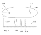
- Fig. 1 shows schematically three towers sections 104, 106, 108 at a site of manufacturing (symbolized by a factory building) and an airship 100 ready to load the tower sections 104, 106, 108.
- the tower sections 104, 106, 108 are shown in an upright orientation, preferably a vertical orientation, but any orientation, such as horizontal, is also covered by the scope of the present invention.
- the site of manufacturing is just one example of a site of loading 110.
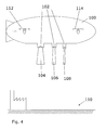
- the airship 100 has propellers 112, 114 for controlling the position of the airship.
- Fig. 2 shows the airship 100 lowered to a position above the tower sections 104, 106, 108 ready for being loaded onto the airship 100.
- Fig. 3 shows schematically the airship 100 comprising cargo attachment elements 102 adapted to receive the wind turbine tower sections 104, 106, 108.
- the cargo attachment elements 102 are shown having three different sizes corresponding to the different sizes of the wind turbine tower sections 104, 106, 108.
- the cargo attachment elements 102 may be identical, but adjustable, to match and securely hold different sizes and shapes of cargo, such as wind turbine tower sections or other pieces of equipment for installing or servicing a wind turbine generator component.
- Fig. 4 shows the airship 100 displaced upwards and with the wind turbine tower sections 104, 106, 108 being suspended below the airship 100.
- the airship 100 may also be designed so that the cargo is partially or fully enclosed inside the airship 100 during transportation.
- the cargo is better protected and the aerodynamic properties of the airship may be improved.
- Partially or fully enclosing the wind turbine tower sections 104, 106, 108 inside the airship 100 during transportation can be particularly important if the transportation is over long distances and/or at high speeds.
- enclosing cargo inside the air ship 100 may result in a need for more complex cargo holds 102 and larger outer dimensions of the airship 100.
- Fig. 5 shows the airship 100 after having transported the wind turbine tower sections 104, 106, 108 to a site of unloading 520 (symbolized by a couple of trees), in the present case at a site of installation of a wind turbine generator.
- a guide element extends from the first tower section 104 to the ground 520.
- the guide element is intended for guiding the first tower section 104 from the airship 100 to the ground 520.
- the guide element may be a flexible guide element such as a wire, a rope, a chain or the like, or the guide element may be a rigid element such as a rod or a lattice structure.
- the guide element is shown being non-tight.
- the guide element when the first tower section 104 is to be lowered from the airship 100 to the ground 520, the guide element may be tightened, possibly by the airship 100 flying upwards.
- the tower section 104 is intended as a bottom tower section of a wind turbine generator tower.
- the guide element extends from the first and bottom tower section 104 to the ground, preferably to a foundation at the ground, for the wind turbine generator to be installed.
- Fig. 6 shows the airship 100 after having unloaded the first tower section 104 at the site of installation and still having the other tower sections 106, 108 suspended in the attachment elements 102.
- a guide element extends from the second tower section 106 to the first tower section 104 already installed at the site.
- the guide element shown in Fig. 6 may be the same guide element as shown in Fig. 5 , with fig. 6 just showing another extension of the guide element, namely an extension between the first bottom tower section 104 and the second intermediate tower section 106.
- the guide element shown in Fig. 6 may be a separate guide element that is similar to the guide element in Fig. 5 .
- the guide element is intended for guiding the second tower section 106 from the airship 100 to the first tower section 104.
- the guide element may be a flexible guide element such as a wire, a rope, a chain or the like, or the guide element may be a rigid element such as a rod or a lattice structure.
- the guide element is shown being non-tight.
- the guide element may be tightened, possibly by the airship 100 flying upwards.
- the second tower section 106 is intended as an intermediate tower section of a wind turbine generator tower.
- the guide element extends from the second intermediate tower section 106 to the first bottom tower section 104.
- Fig. 7 shows the airship 100 after having unloaded the second tower section 106 at the site of installation and still having the third tower section 108 suspended in an attachment element 102.
- a guide element extends from the third tower section 108 to the second tower section 106 already installed at the site.
- the guide element is intended for guiding the third tower section 108 from the airship 100 to the second tower section 106.
- the guide element may be a flexible guide element such as a wire, a rope, a chain or the like, or the guide element may be a rigid element such as a rod or a lattice structure.
- the guide element is shown being non-tight.
- the guide element when the third tower section 108 is to be lowered from the airship 100 to the second tower section 106, the guide element will be tightened, probably by the airship 100 flying upwards.
- the third tower section 108 is intended as a top tower section of a wind turbine generator tower.
- the guide element extends from the third top tower section 108 to the second intermediate tower section 106.
- the guide element shown in Fig. 7 may be the same guide element as shown in Fig. 6 , with 7 just showing another extension of the guide element, namely an extension between the second intermediate tower section 106 and the third top tower section 108.
- the guide element shown in Fig. 7 may even be the same guide element as shown in Fig. 5 , with 7 just showing another extension of the guide element.
- the guide element shown in Fig. 7 may be a separate guide element that is similar to the guide element in Fig. 5 and/or Fig. 6 .
- Fig. 8 shows the airship 100 after having unloaded also the third tower section 106 at the site of installation, thus now having unloaded the first, the second and the third tower sections 104, 106, 108.
- a guide element extends from the airship 100 to the third tower section 108 already installed at the site.
- the guide element may be a flexible guide element such as a wire, a rope, a chain or the like, or the guide element may be a rigid element such as a rod or a lattice structure.
- the guide element shown in Fig. 8 may be the same guide element as shown in Fig. 7 , with Fig. 8 just showing another extension of the guide element, namely an extension between the third top tower section 108 and the airship 100.
- the guide element shown in Fig. 8 may even be the same guide element as shown in Fig. 6 , with Fig. 8 just showing another extension of the guide element.
- the guide element shown in Fig. 8 may even also be the same guide element as shown in Fig. 5 , with Fig. 8 just showing another extension of the guide element.
- the guide element shown in Fig. 8 may be a separate guide element that is similar to any of the above-described guide elements.
- the airship may be maintained in position above the site of installation when unloading the wind turbine tower sections either by means of the one or more guide elements shown, or by means of additional guide elements extending form the airship 100 directly to the ground 520 at the site of installation.
Abstract
The invention relates to a method for handling at least one wind turbine generator component. The method comprises the steps of loading said at least one wind turbine generator component to an airship at a site of loading, transporting the airship with the at least one wind turbine component from the site of loading of the at least one wind turbine generator component to the site of installation of the at least one wind turbine component, and unloading said at least one wind turbine generator component from the airship at the site of unloading by means one or more guide elements extending between the at least one wind turbine generator component and the other wind turbine generator component. The invention also relates to use of an airship for installing wind turbine generator components.
Description
- The invention relates to a method for handling pieces of equipment for installing a wind turbine generator, and in particular to a method for handling one or more wind turbine generator components or one more persons. The invention also relates to an airship and to use of such airship.
- The inventor of the present invention has appreciated that an improved method of handling pieces of equipment for installing a wind turbine generator is of benefit, and has in consequence devised the present invention.
- Installing a wind turbine generator comprises different pieces of equipment and different steps of transportation. The pieces of equipment can be wind turbine generator components themselves including sub stations for supplying the electrical energy to a grid, or the pieces of equipment can be equipment associated with installing a wind turbine generator such as mobile cranes or other installation equipment needed at a site of installation or at another site.
- Cranes are widely used for installation of wind turbine generators, either land-based mobile cranes or stationary cranes, or sea-based barge cranes, or even airborne helicopters used as cranes. Vehicles or vessels are also used for installation of wind turbine generators, including trucks, trains, ships and aircrafts, namely for transporting pieces of equipment from a site of loading to a site of unloading.
- Common to the different vessels and vehicles used for installation of a wind turbine generator is that the vessels or vehicles often are very expensive to use and/or require roads, harbours, airports, or railway stations for loading and unloading the pieces of equipment and/or require sufficiently widespread and stabile roads or railways between the site of loading and the site of unloading.
- It may be seen as an object of the present invention to provide an improved method for handling pieces of equipment for installing a wind turbine generator.
- The objects and advantages of the invention may be obtained by a method for handling at least one wind turbine generator component, said method comprising the steps of
- loading said at least one wind turbine generator component to an airship at a site of loading, said site of loading being different than a site of installation of the wind turbine generator component,
- transporting the airship with the at least one wind turbine component from the site of loading of the at least one wind turbine generator component to the site of installation of the at least one wind turbine component
- unloading said at least one wind turbine generator component from the airship at the site of unloading by installing said at least one wind turbine generator component at another wind turbine generator component by means one or more guide elements extending between the at least one wind turbine generator component and the other wind turbine generator component.
- Unloading said at least one wind turbine generator component from the airship by means one or more guide elements extending between the at least one wind turbine generator component and the other wind turbine generator component may have the advantage of providing an easy and safe means of unloading, said unloading being guided, thus limiting the risk of damages to the component.
- According to a possible aspect of the invention, the at least one wind turbine generator component is one of the following components: a complete wind turbine generator, a wind turbine blade, a wind turbine tower section, a complete wind turbine tower, a wind turbine nacelle, a wind turbine hub, a wind turbine foundation, a generator, a wind turbine gear box, a wind turbine transformer, a wind turbine rectifier, a wind turbine inverter, or a wind turbine bunny comprised of the hub and two wind turbine blades extending obliquely upwards.
- The one wind turbine generator components to be handled by the airship may have the advantage of the different components being a complete wind turbine generator or being part of an entire wind turbine generator can be transported irrespective of the size and/or configuration of the one component.
- According to a possible aspect of the invention, the other wind turbine generator component is one of the following components: a complete wind turbine generator, a wind turbine blade, a wind turbine tower section, a complete wind turbine tower, a wind turbine nacelle, a wind turbine hub, a wind turbine foundation, a generator, a wind turbine gear box, a wind turbine transformer, a wind turbine rectifier, a wind turbine inverter, a wind turbine bunny comprised of the hub and two wind turbine blades extending obliquely upwards, a foundation, the ground, the sea, a vehicle at the ground, or a vessel at the sea.
- The other wind turbine generator components to be handled by the airship may have the advantage of the different components being a complete wind turbine generator or being part of an entire wind turbine generator can be transported irrespective of the size and/or configuration of the other component.
- According to a possible aspect of the invention, the one or more guide elements is extending from and is connected to the airship, further extending to and connected to the wind turbine generator one component and even further extending to an connected to the other wind turbine generator component.
- The guide elements extending from the airship further to the one wind turbine generator component and further to the other wind turbine generator component may have the advantage of the one or same guide element constituting both a guide element between the airship and the other wind turbine generator component and a guide element between the one and the other wind turbine generator component.
- According to a possible aspect of the invention, the one or more guide elements extends from a bottom of the airship, further to a top of the one wind turbine generator component, even further to a bottom of the one wind turbine generator component, and still further to the other wind turbine generator component.
- The guide elements extending from the airship as described above may have the advantage of the one or same guide element constituting both a guide element between the airship and the other wind turbine generator component and a guide element between the one and the other wind turbine generator component and the advantage of proving a safe guiding of the one wind turbine generator component in relation both to the airship and to the other wind turbine generator component.
- According to a possible aspect of the invention, the guide elements comprises
- a first set of guide elements and a second set of guide elements, where
- said first set of guide elements is extending from and connected to the one wind turbine generator component and further is extending to an connected to the another wind turbine generator component, and where
- said second set of guide elements is extending from and is connected to the airship and further is extending to and connected to the another wind turbine generator component.
- Dividing the guide elements into a first set and a second set of guide element may have the advantage of the first set being handled for steady guiding of the airship in relation to the other wind turbine generator component, and the second set being handled for steady guiding of the one wind turbine generator component also in relation to the other wind turbine generator component.
- According to a possible aspect of the invention, the guide elements comprises
- a first set of guide elements and a second set of guide elements, where
- said first set of guide elements is extending from and connected to the one wind turbine generator component and further is extending to an connected to the another wind turbine generator component, and where
- said second set of guide elements is extending from and is connected to the airship and further is extending to and connected to the ground.
- Dividing the guide elements into a first set and a second set of guide elements may have the advantage of the first set being handled for steady guiding of the airship in relation to the ground if the ground is not the other wind turbine generator component, and the second set being handled for steady guiding of the one wind turbine generator component in relation to the other wind turbine generator component.
- According to a possible aspect of the invention, the guide elements comprises
- a first set of guide elements and a second set of guide elements, where
- said first set of guide elements is extending from and connected to the one wind turbine generator component and further is extending to an connected to the another wind turbine generator component, and where
- said second set of guide elements is extending from and is connected to the airship and further is extending to and connected to a sea-vessel.
- Dividing the guide elements into a first set and a second set of guide elements may have the advantage of the first set being handled for steady guiding of the airship in relation to the sea if the sea is not the other wind turbine generator component, and the second set being handled for steady guiding of the one wind turbine generator component in relation to the other wind turbine generator component.
- According to a possible aspect of the invention, the method comprises the steps of initially unloading and installing one wind turbine tower section and subsequently guiding, by means of the one or more guide elements, another wind turbine tower section for being positioned in relation to and for being installed on the one wind turbine tower section.
- Using guide element for installation of one wind turbine tower section on another wind turbine tower section may have the advantage of the one wind turbine tower section being guided steadily, safely and easily, even if the airship is not steadily situated in the air.
- According to a possible aspect of the invention, the one or more guide elements are selected from the group consisting of: one or more flexible ropes, one or more elastic ropes, one or more chains, one or more wires, or one or more rigid rods. One or more flexible ropes, one or more elastic ropes, one or more chains, one or more wires, or one or more rigid rods used for the guide element may have the advantage of possible flexibility, both upwards and downwards and laterally of the guide elements, thus taking up any non-steadiness of the airship in the air.
- According to a possible aspect of the invention, the one or more guide elements extend from or through eyelets provided at the airship and/or at the one wind turbine generator component and/or at the other wind turbine generator component and/or at the ground and/or at the sea-vessel.
- Eyelets for the guide elements may have the advantage of easy and safe fastening of the guide elements to the airship and/or to the one wind turbine generator component and/or to the other wind turbine generator component and/or to the ground and/or to a sea-vessel.
- According to a possible aspect of the invention, a free end of at least one of the one or more guide elements is connected to a traction equipment, and where traction in the free end of the at least one guide element results in a pulling downwards of the one wind turbine generator component from the airship towards the other wind turbine generator component.
- Connecting a free end of at least one of the one or more guide elements to a traction equipment for pulling downwards of the one wind turbine generator component from the airship towards the other wind turbine generator component may have the advantage of controlling guiding of the one wind turbine generator component ion relation to the other wind turbine generator component by other means than moving the airship downwards and/or laterally.
- According to a possible aspect of the invention, the step of unloading said at least one wind turbine generator component from the airship at the site of unloading is performed by the airship being lowered towards the ground or sea at a position for unloading the at least one wind turbine generator component, and that the at least one wind turbine component is detached from the airship when the airship is in the lowered position above the ground or sea without hoisting the wind turbine generator component from the airship.
- The airship being lowered towards the ground or sea at a position for unloading the wind turbine generator component may have the advantage of controlling guiding of the one wind turbine generator component in relation to the other wind turbine generator component by moving the airship downwards.
- According to a possible aspect of the invention, the airship being lowered towards the ground or sea at a position for unloading the at least one wind turbine generator component by a traction force being applied to a free end of at least one of the one or more guide elements.
- Connecting a free end of at least one of the one or more guide elements to a traction equipment for pulling downwards the airship towards the ground or the sea may have the advantage of controlling guiding of the one wind turbine generator component in relation to the other wind turbine generator component by other means than moving the airship downwards and/or laterally only by using moving equipment of the airship.
- According to a possible aspect of the invention, the step of unloading said at least one wind turbine generator component from the an airship at the site of unloading is performed by the airship being positioned above the ground or sea at a position for unloading the at least one wind turbine generator component, and that the at least one wind turbine component is detached from the airship when the airship is in the position above the ground or sea by hoisting the at least one wind turbine generator component from the airship.
- According to a possible aspect of the invention, the at least one wind turbine component is detached from the airship when the airship is in the position above the ground or sea by a releasing of a previously applied traction force being applied to a free end of at least one of the one or more guide elements.
- Connecting a free end of at least one of the one or more guide elements to a traction equipment for lowering downwards the at least one wind turbine generator component from the airship towards the other wind turbine generator component, by releasing the traction force, may have the advantage of controlling guiding of the one wind turbine generator component in relation to the other wind turbine generator component by other means than moving the airship downwards and/or laterally.
- The objects and advantages of the invention may also be obtained by an airship for handling at least one wind turbine generator component, said airship being provided with one or more guide elements extending from and being connected to the airship, and where at least one of the one or more guide elements extend from the airship to a wind turbine generator component.
- According to a possible aspect of the invention, said airship is provided with one or more guide elements extending from and being connected to the airship, and where at least one of the one or more guide elements extend from the airship to the ground or to a sea-vessel.
- According to a possible aspect of the invention,
- a first set of one or more guide elements is extending from and being connected to the airship, and where at least one of the one or more guide elements extend from the airship to the wind turbine generator component, and where
- a second set of one or more guide elements is extending from and being connected to the airship, and where at least one of the one or more guide elements extend from the airship to the ground or to a sea-vessel.
- Dividing the guide elements into a first set and a second set of guide elements may have the advantage of the first set being handled for steady guiding of the airship in relation to the ground or a sea-vessel, and the second set being handled for steady guiding of the wind turbine generator section in relation to the other wind turbine generator component.
- According to a possible aspect of the invention, the one or more guide elements is extending from and being connected to the airship, and where at least one of the one or more guide elements extend from the airship to the wind turbine generator component, and where
- said one or more guide elements also is extending from and being connected to the airship, and where at least one of the one or more guide elements extend from the airship to the ground or to a sea-vessel.
- The guide elements extending from the airship further to the one wind turbine generator component and further to the ground or a sea-vessel may have the advantage of the one or same guide element constituting both a guide element between the airship and the ground or sea, and a guide element between the wind turbine generator component and the other wind turbine generator component.
- The objects and advantages of the invention may also be obtained by use of an airship according to any of claims 17-20 for installing a wind turbine generator component to an on-shore or off-shore foundation for a wind turbine generator during installation of or dismantling of a wind turbine generator.
- The objects and advantages of the invention may also be obtained by use of an airship according to any of claims 17-21 for installing a wind turbine generator component to another wind turbine generator component during installation of or dismantling of a wind turbine generator.
- Different applications and uses in accordance with the present invention include:
- Using an airship for lifting components in wind where the wind on a windy site is used by a specially made and designed airship or auxiliary lifting balloon which may generate enough buoyancy to lift wind turbine generator parts from the ground to the desired elevated positions during the installation;
- using an airship for laying an electrical cable from the airship, either a ground cable or more preferably an off-shore cable;
- using an airship for working as a heavy duty crane on the site of installation;
- using a specialised airship to transport and install the nacelle onto the towers;
- using an airship to place tower or tower sections on the desired foundation by transporting them vertically during parts of the transport or during the entire transport;
- using an airship used as a combination of a lifting means, e.g. crane, and a transportation means to install an off-shore wind turbine generator by transporting a wind turbine generator, which is assembled on-shore prior to transportation, in a completely, or almost completely, assembled condition to the off-shore site of installation;
- using one or more airships as auxiliary lifting balloons being applied during the installation, for example to circumvent the use of a crane;
- using helicopters for pulling and/or manipulating the auxiliary lifting balloons; erecting full wind turbine generator off-shore, which is particularly advantageous for reducing cost of installation at far and remote sites, e.g, on the sea;
- using an airship for pulling or dragging off-shore foundations to the site of installation;
- using an airship for bringing accommodations, workshops (incl. light working equipments), offices etc. to the site of installation;
- using an airship to carry a fuel tank to refuel working equipment, for example for refuelling with gas, hydrogen or electricity;
- using an airship for bulk carrying where the present invention, in addition to carrying large parts and elements of a wind turbine generator, is applied for transporting raw materials, semi-manufactured elements, or large tools, e.g. blade moulds, to sites of production or manufacturing;
- using an airship for transporting blade moulds to local site factories; using an airship for transporting larger components for production of larger tower flanges that could help save steel for the towers;
- using an airship for transporting of raw large materials for production (larger steel plates);
- using an airship for transporting from a barge, to a ship and further to an airship, where pre-assembled parts, for example the nacelle, hub, and rotors may assembled on the point of installation, may be transported to a site of installation;
- using an airship for transporting prefabricated crane pads to and around the site by an airship, an advantage being to decrease time on site and cost for the costumer;
- using an airship for transporting prefabricated foundations by an airship, which could decrease erection time and cost;
- using an airship to transport and deploy a met-mast, or alternatively the airship may function as a met-mast, for example by anchoring the airship to a desired position and height.
- using an airship to reach today's almost completely unreachable possible sites of installation , e.g. in Mongolia, in Peru etc.
- When referring to an advantage, it must be understood that this advantage may be seen as a possible advantage provided by the invention, but it may also be understood that the invention is particularly, but not exclusively, advantageous for obtaining the described advantage.
- In general the various aspects and advantages of the invention may be combined and coupled in any way possible within the scope of the invention.
- Airships for performing one or more of the methods according to the invention may be specifically developed for performing the one or more methods.
- However, hereby incorporated by reference are already developed, existing or projected airships from one or more of the following developers and manufacturers of airships: Skycat/Hybrid Air Vehicles, Skyhook International, Lockheed Martin, RosAeroSystems, 21st Century Airships, Airship.org, all of which are suited for performing one or more of the methods according to the invention.
- These and other aspects, features and/or advantages of the invention will be apparent from and elucidated with reference to the description hereinafter.
- The method steps and the use and the airship according to the invention will now be described in more detail with regard to the accompanying figures. The figures show one way of implementing the present invention and is not to be construed as being limiting to other possible embodiments falling within the scope of the attached claim set.
-
Figs. 1-8 show method steps and uses of an airship, according to an overall installation concept of the invention. - In the following figures the invention will be described with reference to transportation and installation of wind turbine tower sections for raising a wind turbine tower for a wind turbine generator. The wind turbine tower is shown as consisting of three sections for illustrative purposes only. Other wind turbine generator components than wind turbine tower sections, e.g., blades, a nacelle, or a hub, may be transported and installed by the method described.
- Any number of sections is possible within the scope of the invention, and as described above the present invention can be used for handling and transporting of a range of pieces of equipment for installing a wind turbine generator, either equipment being components of the wind turbine tower itself, or equipment such as substations and the like for delivering electrical power from the wind turbine generator, or equipment such as cranes and the like for installing or servicing the wind turbine generator.
-
Fig. 1 shows schematically threetowers sections airship 100 ready to load thetower sections tower sections - The site of manufacturing is just one example of a site of
loading 110. Theairship 100 haspropellers Fig. 2 shows theairship 100 lowered to a position above thetower sections airship 100. -
Fig. 3 shows schematically theairship 100 comprisingcargo attachment elements 102 adapted to receive the windturbine tower sections cargo attachment elements 102 are shown having three different sizes corresponding to the different sizes of the windturbine tower sections cargo attachment elements 102 may be identical, but adjustable, to match and securely hold different sizes and shapes of cargo, such as wind turbine tower sections or other pieces of equipment for installing or servicing a wind turbine generator component. -
Fig. 4 shows theairship 100 displaced upwards and with the windturbine tower sections airship 100. If desired, theairship 100 may also be designed so that the cargo is partially or fully enclosed inside theairship 100 during transportation. Hereby, the cargo is better protected and the aerodynamic properties of the airship may be improved. Partially or fully enclosing the windturbine tower sections airship 100 during transportation can be particularly important if the transportation is over long distances and/or at high speeds. On the other hand, enclosing cargo inside theair ship 100 may result in a need for more complex cargo holds 102 and larger outer dimensions of theairship 100. -
Fig. 5 shows theairship 100 after having transported the windturbine tower sections - A guide element extends from the
first tower section 104 to theground 520. The guide element is intended for guiding thefirst tower section 104 from theairship 100 to theground 520. The guide element may be a flexible guide element such as a wire, a rope, a chain or the like, or the guide element may be a rigid element such as a rod or a lattice structure. - In the embodiment shown, the guide element is shown being non-tight.
- However, when the
first tower section 104 is to be lowered from theairship 100 to theground 520, the guide element may be tightened, possibly by theairship 100 flying upwards. Thetower section 104 is intended as a bottom tower section of a wind turbine generator tower. Thus, the guide element extends from the first andbottom tower section 104 to the ground, preferably to a foundation at the ground, for the wind turbine generator to be installed. -
Fig. 6 shows theairship 100 after having unloaded thefirst tower section 104 at the site of installation and still having theother tower sections attachment elements 102. - A guide element extends from the
second tower section 106 to thefirst tower section 104 already installed at the site. The guide element shown inFig. 6 may be the same guide element as shown inFig. 5 , withfig. 6 just showing another extension of the guide element, namely an extension between the firstbottom tower section 104 and the secondintermediate tower section 106. Alternatively, the guide element shown inFig. 6 may be a separate guide element that is similar to the guide element inFig. 5 . - In either embodiment, the guide element is intended for guiding the
second tower section 106 from theairship 100 to thefirst tower section 104. The guide element may be a flexible guide element such as a wire, a rope, a chain or the like, or the guide element may be a rigid element such as a rod or a lattice structure. - In the embodiment shown, the guide element is shown being non-tight.
- However, when the
second tower section 106 is to be lowered from theairship 100 to thefirst tower section 104, the guide element may be tightened, possibly by theairship 100 flying upwards. Thesecond tower section 106 is intended as an intermediate tower section of a wind turbine generator tower. Thus, the guide element extends from the secondintermediate tower section 106 to the firstbottom tower section 104. -
Fig. 7 shows theairship 100 after having unloaded thesecond tower section 106 at the site of installation and still having thethird tower section 108 suspended in anattachment element 102. - A guide element extends from the
third tower section 108 to thesecond tower section 106 already installed at the site. - Regardless of the embodiment, the guide element is intended for guiding the
third tower section 108 from theairship 100 to thesecond tower section 106. The guide element may be a flexible guide element such as a wire, a rope, a chain or the like, or the guide element may be a rigid element such as a rod or a lattice structure. - In the embodiment shown, the guide element is shown being non-tight.
- However, when the
third tower section 108 is to be lowered from theairship 100 to thesecond tower section 106, the guide element will be tightened, probably by theairship 100 flying upwards. Thethird tower section 108 is intended as a top tower section of a wind turbine generator tower. Thus, the guide element extends from the thirdtop tower section 108 to the secondintermediate tower section 106. - The guide element shown in
Fig. 7 may be the same guide element as shown inFig. 6 , with 7 just showing another extension of the guide element, namely an extension between the secondintermediate tower section 106 and the thirdtop tower section 108. The guide element shown inFig. 7 may even be the same guide element as shown inFig. 5 , with 7 just showing another extension of the guide element. Alternatively, the guide element shown inFig. 7 may be a separate guide element that is similar to the guide element inFig. 5 and/orFig. 6 . -
Fig. 8 shows theairship 100 after having unloaded also thethird tower section 106 at the site of installation, thus now having unloaded the first, the second and thethird tower sections - A guide element extends from the
airship 100 to thethird tower section 108 already installed at the site. The guide element may be a flexible guide element such as a wire, a rope, a chain or the like, or the guide element may be a rigid element such as a rod or a lattice structure. - The guide element shown in
Fig. 8 may be the same guide element as shown inFig. 7 , withFig. 8 just showing another extension of the guide element, namely an extension between the thirdtop tower section 108 and theairship 100. The guide element shown inFig. 8 may even be the same guide element as shown inFig. 6 , withFig. 8 just showing another extension of the guide element. The guide element shown inFig. 8 may even also be the same guide element as shown inFig. 5 , withFig. 8 just showing another extension of the guide element. Alternatively, the guide element shown inFig. 8 may be a separate guide element that is similar to any of the above-described guide elements. - The airship may be maintained in position above the site of installation when unloading the wind turbine tower sections either by means of the one or more guide elements shown, or by means of additional guide elements extending form the
airship 100 directly to theground 520 at the site of installation. - Although the present invention has been described in connection with the specified embodiments, it should not be construed as being in any way limited to the presented examples. The scope of the present invention is set out by the accompanying claim set. In the context of the claims, the terms "comprising" or "comprises" do not exclude other possible elements or steps. Also, the mentioning of references such as "a" or "ain" etc. should not be construed as excluding a plurality. The use of reference signs in the claims with respect to elements indicated in the figures shall also not be construed as limiting the scope of the invention. Furthermore, individual features mentioned in different claims, may possibly be advantageously combined, and the mentioning of these features in different claims does not exclude that a combination of features is not possible and advantageous.
Claims (22)
1. A method for handling at least one wind turbine generator component, said method comprising the steps of
- loading said at least one wind turbine generator component to an airship at a site of loading, said site of loading being different than a site of installation of the wind turbine generator component,
- transporting the airship with the at least one wind turbine component from the site of loading of the at least one wind turbine generator component to the site of installation of the at least one wind turbine component
- unloading said at least one wind turbine generator component from the airship at the site of unloading by installing said at least one wind turbine generator component at another wind turbine generator component by means one or more guide elements extending between the at least one wind turbine generator component and the other wind turbine generator component.
2. A method according to claim 1, where the at least one wind turbine generator component is one of the following components: a complete wind turbine generator, a wind turbine blade, a wind turbine tower section, a complete wind turbine tower, a wind turbine nacelle, a wind turbine hub, a wind turbine foundation, a generator, a wind turbine gear box, a wind turbine transformer, a wind turbine rectifier, a wind turbine inverter, or a wind turbine bunny comprised of the hub and two wind turbine blades extending obliquely upwards.
2. A method according to claim 1 or claim 2, where the other wind turbine generator component is one of the following components: a complete wind turbine generator, a wind turbine blade, a wind turbine tower section, a complete wind turbine tower, a wind turbine nacelle, a wind turbine hub, a wind turbine foundation, a generator, a wind turbine gear box, a wind turbine transformer, a wind turbine rectifier, a wind turbine inverter, a wind turbine bunny comprised of the hub and two wind turbine blades extending obliquely upwards, a foundation, the ground, the sea, a vehicle at the ground, or a vessel at the sea.
4. A method according to any of claims 1-3, where the one or more guide elements is extending from and is connected to the airship, further extending to and connected to the at least one wind turbine generator component and even further extending to an connected to the other wind turbine generator component.
5. A method according to claim 4, where the one or more guide elements extends from a bottom of the airship, further to a top of the at least one wind turbine generator component, even further to a bottom of the at least one wind turbine generator component, and still further to the other wind turbine generator component.
6. A method according to any of claims 1-5, where the one or more guide elements comprises
- a first set of guide elements and a second set of guide elements, where
- said first set of guide elements is extending from and connected to the at least one wind turbine generator component and further is extending to and connected to the another wind turbine generator component, and where
- said second set of guide elements is extending from and is connected to the airship and further is extending to and connected to the another wind turbine generator component.
7. A method according to any of claims 1-5, where the guide elements comprises
- a first set of guide elements and a second set of guide elements, where
- said first set of guide elements is extending from and connected to the at least one wind turbine generator component and further is extending to an connected to the another wind turbine generator component, and where
- said second set of guide elements is extending from and is connected to the airship and further is extending to and connected to the ground.
8. A method according to any of claims 1-5, where the one or more guide elements comprises
- a first set of guide elements and a second set of guide elements, where
- said first set of guide elements is extending from and connected to the at least one wind turbine generator component and further is extending to an connected to the another wind turbine generator component, and where
- said second set of guide elements is extending from and is connected to the airship and further is extending to and connected to a sea-vessel.
9. A method according to any of claims 1-8, where the method comprises the steps of initially unloading and installing one wind turbine tower section and subsequently guiding, by means of the one or more guide elements, another wind turbine tower section for said other wind turbine tower section to be positioned in relation to and to be installed on said one wind turbine tower section.
10. A method according to any of claims 1-9, wherein the one or more guide elements are selected from the group consisting of: one or more flexible ropes, one or more elastic ropes, one or more chains, one or more wires, or one or more rigid rods.
11. A method according to any of claims 1-10, where the one or more guide elements extend from or through eyelets provided at the airship and/or at the at least one wind turbine generator component and/or at the other wind turbine generator component and/or at the ground and/or at the sea-vessel.
12. A method according to any of claim 1-11, where a free end of at least one of the one or more guide elements is connected to a traction equipment, and where traction in the free end of the at least one guide element results in a pulling downwards of the at least one wind turbine generator component from the airship towards the other wind turbine generator component.
13. A method according to any of claims 1-12, where the step of unloading said at least one wind turbine generator component from the airship at the site of unloading is performed by the airship being lowered towards the ground or sea at a position for unloading the at least one wind turbine generator component, and that the at least one wind turbine component is detached from the airship when the airship is in the lowered position above the ground or sea without hoisting the at least one wind turbine generator component from the airship.
14. A method according to claim 13, where the airship being lowered towards the ground or sea at a position for unloading the at least one wind turbine generator component by a traction force being applied to a free end of at least on of the one or more guide elements.
15. A method according to any of claims 1-11, where the step of unloading said at least one wind turbine generator component from the an airship at the site of unloading is performed by the airship being positioned above the ground or sea at a position for unloading the at least one wind turbine generator component, and that the at least one wind turbine component is detached from the airship when the airship is in the position above the ground or sea by hoisting the at least one wind turbine generator component from the airship.
16. A method according to claim 15, where the at least one wind turbine component is detached from the airship when the airship is in the position above the ground or sea by a releasing of a previously applied traction force being applied to a free end of at least one of the one or more guide elements.
17. An airship for handling at least one wind turbine generator component, said airship being provided with one or more guide elements extending from and being connected to the airship, and where at least one of the one or more guide elements extend from the airship to a wind turbine generator component.
18. An airship for handling at least one wind turbine generator component, said airship being provided with one or more guide elements extending from and being connected to the airship, and where at least one of the one or more guide elements extend from the airship to the ground or to a sea-vessel.
19. An airship according to claim 17 and claim 18, where
- a first set of one or more guide elements is extending from and being connected to the airship, and where at least one of the one or more guide elements extend from the airship to the wind turbine tower component, and where
- a second set of one or more guide elements is extending from and being connected to the airship, and where at least one of the one or more guide elements extend from the airship to the ground or to a sea-vessel.
20. An airship according to claim 17 and claim 18, where
- one or more guide elements is extending from and being connected to the airship, and where at least one of the one or more guide elements extend from the airship to the wind turbine tower component, and where
- said one or more guide elements also is extending from and being connected to the airship, and where at least one of the one or more guide elements extend from the airship to the ground or to a sea-vessel.
21. Use of an airship according to any of claims 17-20 for installing a wind turbine generator component to an on-shore or off-shore foundation for a wind turbine generator during installation of or dismantling of a wind turbine generator.
22. Use of an airship according to any of claim 17-21 for installing a wind turbine generator component to another wind turbine generator component during installation of or dismantling of a wind turbine generator.
Priority Applications (7)
| Application Number | Priority Date | Filing Date | Title |
|---|---|---|---|
| EP09164207A EP2272754A1 (en) | 2009-06-30 | 2009-06-30 | Wind turbine generator installation by airship |
| EP10724259.6A EP2443031B1 (en) | 2009-06-15 | 2010-06-15 | Wind turbine generator installation by airship |
| CN201080025449.3A CN102803070B (en) | 2009-06-15 | 2010-06-15 | Wind turbine generator installation by airship |
| BRPI1009025-8A BRPI1009025B1 (en) | 2009-06-15 | 2010-06-15 | method for handling at least one component of a wind generator |
| US13/377,380 US9022315B2 (en) | 2009-06-15 | 2010-06-15 | Wind turbine generator installation by airship |
| ES10724259T ES2431070T3 (en) | 2009-06-15 | 2010-06-15 | Installation of wind turbine generator by airship |
| PCT/DK2010/050142 WO2010145665A1 (en) | 2009-06-15 | 2010-06-15 | Wind turbine generator installation by airship |
Applications Claiming Priority (1)
| Application Number | Priority Date | Filing Date | Title |
|---|---|---|---|
| EP09164207A EP2272754A1 (en) | 2009-06-30 | 2009-06-30 | Wind turbine generator installation by airship |
Publications (1)
| Publication Number | Publication Date |
|---|---|
| EP2272754A1 true EP2272754A1 (en) | 2011-01-12 |
Family
ID=41461103
Family Applications (2)
| Application Number | Title | Priority Date | Filing Date |
|---|---|---|---|
| EP09164207A Withdrawn EP2272754A1 (en) | 2009-06-15 | 2009-06-30 | Wind turbine generator installation by airship |
| EP10724259.6A Not-in-force EP2443031B1 (en) | 2009-06-15 | 2010-06-15 | Wind turbine generator installation by airship |
Family Applications After (1)
| Application Number | Title | Priority Date | Filing Date |
|---|---|---|---|
| EP10724259.6A Not-in-force EP2443031B1 (en) | 2009-06-15 | 2010-06-15 | Wind turbine generator installation by airship |
Country Status (6)
| Country | Link |
|---|---|
| US (1) | US9022315B2 (en) |
| EP (2) | EP2272754A1 (en) |
| CN (1) | CN102803070B (en) |
| BR (1) | BRPI1009025B1 (en) |
| ES (1) | ES2431070T3 (en) |
| WO (1) | WO2010145665A1 (en) |
Cited By (3)
| Publication number | Priority date | Publication date | Assignee | Title |
|---|---|---|---|---|
| WO2012052029A1 (en) * | 2010-10-20 | 2012-04-26 | Vestas Wind Systems A/S | Foundation for a wind turbine and method of making same |
| WO2019001664A1 (en) * | 2017-06-30 | 2019-01-03 | Vestas Wind Systems A/S | System and method for handling wind turbine components for assembly thereof |
| WO2019092471A1 (en) * | 2017-11-13 | 2019-05-16 | Total Sa | A method for transporting a payload to a target location, and related hybrid airship |
Families Citing this family (4)
| Publication number | Priority date | Publication date | Assignee | Title |
|---|---|---|---|---|
| DE102012010019B4 (en) * | 2012-05-22 | 2022-08-04 | Spanset Axzion Gmbh | Load handling equipment for mounting objects in wind-affected areas |
| CN106218849A (en) * | 2016-04-02 | 2016-12-14 | 吕怀民 | Aerial wind energy power station formula aircraft and aerial fixing aircraft device |
| WO2019001660A1 (en) * | 2017-06-30 | 2019-01-03 | Vestas Wind Systems A/S | Handling a wind turbine blade using an airship |
| EP3759042B1 (en) * | 2018-03-02 | 2024-04-10 | Vestas Wind Systems A/S | System and method for handling wind turbine components for assembly thereof |
Citations (4)
| Publication number | Priority date | Publication date | Assignee | Title |
|---|---|---|---|---|
| EP0054508A1 (en) * | 1981-02-03 | 1982-06-23 | Geilinger AG | Device for mounting building elements, e.g. masts |
| DE29720711U1 (en) * | 1997-11-21 | 1998-01-08 | Liebherr Werk Ehingen | Aircraft for the transportation of goods |
| WO2006010783A1 (en) * | 2004-06-18 | 2006-02-02 | Jorma Lindberg | Wind-, wave- and current power stations with different foundation solutions and methods how to manufacture, transport, install and operate these power stations |
| WO2008084971A1 (en) * | 2007-01-11 | 2008-07-17 | Dong Taek Suh | Method of establishing sea wind power generator using the leading rail |
Family Cites Families (15)
| Publication number | Priority date | Publication date | Assignee | Title |
|---|---|---|---|---|
| US3116037A (en) * | 1961-12-27 | 1963-12-31 | Raven Ind Inc | Balloon body structure for towed balloon |
| US4055316A (en) * | 1976-04-07 | 1977-10-25 | John Lester Chipper | Method and equipment for aerial transport |
| DE19625297A1 (en) * | 1996-06-25 | 1998-01-08 | Cargolifter Ag | Process for the targeted depositing or picking up of goods and people from aircraft |
| US20020109045A1 (en) * | 2000-11-21 | 2002-08-15 | Cargolifter, Inc. | Spherical LTA cargo transport system |
| US20070102571A1 (en) * | 2005-10-20 | 2007-05-10 | Colting Hokan S | Airship for lifting heavy loads & methods of operation |
| DE502006007457D1 (en) * | 2005-12-06 | 2010-08-26 | Delcon Deutsche Luftfahrt Cons | FLIGHT TRANSPORTER |
| CA2637404C (en) * | 2006-01-17 | 2013-04-30 | Vestas Wind Systems A/S | A wind turbine tower, a wind turbine, a wind turbine tower elevator and a method for assembling a wind turbine tower |
| US8157205B2 (en) * | 2006-03-04 | 2012-04-17 | Mcwhirk Bruce Kimberly | Multibody aircrane |
| US8020805B2 (en) * | 2006-07-31 | 2011-09-20 | The United States Of America As Represented By The Administrator Of The National Aeronautics And Space Administration | High altitude airship configuration and power technology and method for operation of same |
| CA2557893A1 (en) * | 2006-08-29 | 2008-02-29 | Skyhook International Inc. | Hybrid lift air vehicle |
| DE102007043426A1 (en) * | 2007-09-12 | 2009-03-19 | Cl Cargolifter Gmbh & Co. Kgaa | Method and arrangement for transporting elongate, bulky goods |
| US8141814B2 (en) * | 2007-11-26 | 2012-03-27 | The Boeing Company | Lighter-than-air vertical load lifting system |
| US20110116905A1 (en) * | 2008-03-11 | 2011-05-19 | Cl Cargolifter Gmbh & Co. Kg A.A. | Method and apparatus for transporting elongated, cumbersome loads |
| US8205835B2 (en) * | 2009-05-14 | 2012-06-26 | Wiley Jeremy A | Systems and methods for aerial cabled transportation |
| US20110192938A1 (en) * | 2010-02-09 | 2011-08-11 | Northrop Grumman Systems Corporation | Wind power generation system for lighter than air (lta) platforms |
-
2009
- 2009-06-30 EP EP09164207A patent/EP2272754A1/en not_active Withdrawn
-
2010
- 2010-06-15 CN CN201080025449.3A patent/CN102803070B/en not_active Expired - Fee Related
- 2010-06-15 BR BRPI1009025-8A patent/BRPI1009025B1/en not_active IP Right Cessation
- 2010-06-15 ES ES10724259T patent/ES2431070T3/en active Active
- 2010-06-15 WO PCT/DK2010/050142 patent/WO2010145665A1/en active Application Filing
- 2010-06-15 US US13/377,380 patent/US9022315B2/en active Active
- 2010-06-15 EP EP10724259.6A patent/EP2443031B1/en not_active Not-in-force
Patent Citations (4)
| Publication number | Priority date | Publication date | Assignee | Title |
|---|---|---|---|---|
| EP0054508A1 (en) * | 1981-02-03 | 1982-06-23 | Geilinger AG | Device for mounting building elements, e.g. masts |
| DE29720711U1 (en) * | 1997-11-21 | 1998-01-08 | Liebherr Werk Ehingen | Aircraft for the transportation of goods |
| WO2006010783A1 (en) * | 2004-06-18 | 2006-02-02 | Jorma Lindberg | Wind-, wave- and current power stations with different foundation solutions and methods how to manufacture, transport, install and operate these power stations |
| WO2008084971A1 (en) * | 2007-01-11 | 2008-07-17 | Dong Taek Suh | Method of establishing sea wind power generator using the leading rail |
Cited By (7)
| Publication number | Priority date | Publication date | Assignee | Title |
|---|---|---|---|---|
| WO2012052029A1 (en) * | 2010-10-20 | 2012-04-26 | Vestas Wind Systems A/S | Foundation for a wind turbine and method of making same |
| US10107265B2 (en) | 2010-10-20 | 2018-10-23 | Mhi Vestas Offshore Wind A/S | Foundation for a wind turbine and method of making same |
| WO2019001664A1 (en) * | 2017-06-30 | 2019-01-03 | Vestas Wind Systems A/S | System and method for handling wind turbine components for assembly thereof |
| US11391267B2 (en) | 2017-06-30 | 2022-07-19 | Vestas Wind Systems A/S | System and method for handling wind turbine components for assembly thereof |
| WO2019092471A1 (en) * | 2017-11-13 | 2019-05-16 | Total Sa | A method for transporting a payload to a target location, and related hybrid airship |
| CN111479748A (en) * | 2017-11-13 | 2020-07-31 | 道达尔公司 | Method of transporting payload to target location and related hybrid airship |
| US11753135B2 (en) | 2017-11-13 | 2023-09-12 | Total Sa | Method for transporting a payload to a target location, and related hybrid airship |
Also Published As
| Publication number | Publication date |
|---|---|
| CN102803070A (en) | 2012-11-28 |
| BRPI1009025A2 (en) | 2017-06-06 |
| EP2443031A1 (en) | 2012-04-25 |
| BRPI1009025B1 (en) | 2020-11-10 |
| ES2431070T3 (en) | 2013-11-25 |
| CN102803070B (en) | 2014-12-10 |
| WO2010145665A1 (en) | 2010-12-23 |
| EP2443031B1 (en) | 2013-09-18 |
| US20120091274A1 (en) | 2012-04-19 |
| US9022315B2 (en) | 2015-05-05 |
Similar Documents
| Publication | Publication Date | Title |
|---|---|---|
| EP2443031B1 (en) | Wind turbine generator installation by airship | |
| JP6804634B2 (en) | Methods and equipment for maintenance of wind turbine components | |
| EP1843964B1 (en) | Lifting device for a wind turbine generator | |
| US20170363070A1 (en) | Methods and Systems of Maintaining an Offshore Power Plant | |
| EP2487363A1 (en) | Lifting system and method for lifting rotor blades of wind turbines | |
| TWI638946B (en) | Methods and systems for maintaining an offshore power plant having airborne power generating craft | |
| US20170363069A1 (en) | Systems and Methods for Offshore Power Generation Using Airborne Power Generating Craft Tethered to a Floating Structure | |
| US9103319B2 (en) | Wind turbine generator service by airship | |
| CN108163179B (en) | Near space aerostat issuing method and apparatus | |
| WO2017218117A1 (en) | Systems and methods for offshore power generation using airborne power generating craft | |
| CN201694361U (en) | Special engineering ship for integral transportation and installation of offshore wind turbine | |
| EP3438375A1 (en) | Methods and systems for performing rope access maintenance operations in vertical structures | |
| EP2269908A1 (en) | Wind turbine generator airship flying concept | |
| EP4184006A1 (en) | Method for the arrangement of at least one component during the installation of a wind turbine | |
| RU162643U1 (en) | DEVICE FOR PLACING EQUIPMENT OF DIFFERENT FUNCTIONAL PURPOSE IN THE GROUND SPACE | |
| DK201671003A1 (en) | Method and apparatus for installing and servicing wind turbine generators | |
| DK201770540A8 (en) | A method for handling a device connected to a crane | |
| RU2356785C1 (en) | Airborne power station |
Legal Events
| Date | Code | Title | Description |
|---|---|---|---|
| PUAI | Public reference made under article 153(3) epc to a published international application that has entered the european phase |
Free format text: ORIGINAL CODE: 0009012 |
|
| AK | Designated contracting states |
Kind code of ref document: A1 Designated state(s): AT BE BG CH CY CZ DE DK EE ES FI FR GB GR HR HU IE IS IT LI LT LU LV MC MK MT NL NO PL PT RO SE SI SK TR |
|
| AX | Request for extension of the european patent |
Extension state: AL BA RS |
|
| RAP1 | Party data changed (applicant data changed or rights of an application transferred) |
Owner name: VESTAS WIND SYSTEMS A/S |
|
| STAA | Information on the status of an ep patent application or granted ep patent |
Free format text: STATUS: THE APPLICATION IS DEEMED TO BE WITHDRAWN |
|
| 18D | Application deemed to be withdrawn |
Effective date: 20110713 |