EP2272624A1 - Lathe with two workpiece spindles - Google Patents
Lathe with two workpiece spindles Download PDFInfo
- Publication number
- EP2272624A1 EP2272624A1 EP09008991A EP09008991A EP2272624A1 EP 2272624 A1 EP2272624 A1 EP 2272624A1 EP 09008991 A EP09008991 A EP 09008991A EP 09008991 A EP09008991 A EP 09008991A EP 2272624 A1 EP2272624 A1 EP 2272624A1
- Authority
- EP
- European Patent Office
- Prior art keywords
- spindle
- workpiece
- spindles
- tool
- lathe
- Prior art date
- Legal status (The legal status is an assumption and is not a legal conclusion. Google has not performed a legal analysis and makes no representation as to the accuracy of the status listed.)
- Granted
Links
- 238000003754 machining Methods 0.000 claims abstract description 16
- 230000033001 locomotion Effects 0.000 claims description 27
- 238000012545 processing Methods 0.000 claims description 20
- 230000008878 coupling Effects 0.000 claims description 4
- 238000010168 coupling process Methods 0.000 claims description 4
- 238000005859 coupling reaction Methods 0.000 claims description 4
- 239000002131 composite material Substances 0.000 claims description 3
- 230000001172 regenerating effect Effects 0.000 claims description 2
- 230000008859 change Effects 0.000 description 10
- 238000005520 cutting process Methods 0.000 description 6
- 230000004048 modification Effects 0.000 description 4
- 238000012986 modification Methods 0.000 description 4
- 239000007787 solid Substances 0.000 description 4
- 230000008901 benefit Effects 0.000 description 3
- 238000001816 cooling Methods 0.000 description 3
- 239000000463 material Substances 0.000 description 3
- 238000003860 storage Methods 0.000 description 3
- XLYOFNOQVPJJNP-UHFFFAOYSA-N water Substances O XLYOFNOQVPJJNP-UHFFFAOYSA-N 0.000 description 3
- 238000010586 diagram Methods 0.000 description 2
- 238000005516 engineering process Methods 0.000 description 2
- 238000004519 manufacturing process Methods 0.000 description 2
- 238000000034 method Methods 0.000 description 2
- 230000008569 process Effects 0.000 description 2
- 238000011084 recovery Methods 0.000 description 2
- 230000020347 spindle assembly Effects 0.000 description 2
- 229910000831 Steel Inorganic materials 0.000 description 1
- 230000001133 acceleration Effects 0.000 description 1
- XAGFODPZIPBFFR-UHFFFAOYSA-N aluminium Chemical compound [Al] XAGFODPZIPBFFR-UHFFFAOYSA-N 0.000 description 1
- 229910052782 aluminium Inorganic materials 0.000 description 1
- 238000004364 calculation method Methods 0.000 description 1
- 238000005266 casting Methods 0.000 description 1
- 238000010276 construction Methods 0.000 description 1
- 239000000498 cooling water Substances 0.000 description 1
- 230000001419 dependent effect Effects 0.000 description 1
- 238000013461 design Methods 0.000 description 1
- 238000011161 development Methods 0.000 description 1
- 230000018109 developmental process Effects 0.000 description 1
- 230000000694 effects Effects 0.000 description 1
- 230000005611 electricity Effects 0.000 description 1
- 230000002706 hydrostatic effect Effects 0.000 description 1
- 230000006698 induction Effects 0.000 description 1
- 238000009434 installation Methods 0.000 description 1
- 238000012423 maintenance Methods 0.000 description 1
- 238000005457 optimization Methods 0.000 description 1
- 238000005096 rolling process Methods 0.000 description 1
- 210000002023 somite Anatomy 0.000 description 1
- 125000006850 spacer group Chemical group 0.000 description 1
- 229910001220 stainless steel Inorganic materials 0.000 description 1
- 239000010935 stainless steel Substances 0.000 description 1
- 239000010959 steel Substances 0.000 description 1
- 230000001360 synchronised effect Effects 0.000 description 1
- 239000004753 textile Substances 0.000 description 1
Images


Classifications
-
- B—PERFORMING OPERATIONS; TRANSPORTING
- B23—MACHINE TOOLS; METAL-WORKING NOT OTHERWISE PROVIDED FOR
- B23Q—DETAILS, COMPONENTS, OR ACCESSORIES FOR MACHINE TOOLS, e.g. ARRANGEMENTS FOR COPYING OR CONTROLLING; MACHINE TOOLS IN GENERAL CHARACTERISED BY THE CONSTRUCTION OF PARTICULAR DETAILS OR COMPONENTS; COMBINATIONS OR ASSOCIATIONS OF METAL-WORKING MACHINES, NOT DIRECTED TO A PARTICULAR RESULT
- B23Q1/00—Members which are comprised in the general build-up of a form of machine, particularly relatively large fixed members
- B23Q1/25—Movable or adjustable work or tool supports
- B23Q1/64—Movable or adjustable work or tool supports characterised by the purpose of the movement
- B23Q1/66—Worktables interchangeably movable into operating positions
-
- B—PERFORMING OPERATIONS; TRANSPORTING
- B23—MACHINE TOOLS; METAL-WORKING NOT OTHERWISE PROVIDED FOR
- B23Q—DETAILS, COMPONENTS, OR ACCESSORIES FOR MACHINE TOOLS, e.g. ARRANGEMENTS FOR COPYING OR CONTROLLING; MACHINE TOOLS IN GENERAL CHARACTERISED BY THE CONSTRUCTION OF PARTICULAR DETAILS OR COMPONENTS; COMBINATIONS OR ASSOCIATIONS OF METAL-WORKING MACHINES, NOT DIRECTED TO A PARTICULAR RESULT
- B23Q1/00—Members which are comprised in the general build-up of a form of machine, particularly relatively large fixed members
- B23Q1/01—Frames, beds, pillars or like members; Arrangement of ways
- B23Q1/015—Frames, beds, pillars
-
- B—PERFORMING OPERATIONS; TRANSPORTING
- B23—MACHINE TOOLS; METAL-WORKING NOT OTHERWISE PROVIDED FOR
- B23Q—DETAILS, COMPONENTS, OR ACCESSORIES FOR MACHINE TOOLS, e.g. ARRANGEMENTS FOR COPYING OR CONTROLLING; MACHINE TOOLS IN GENERAL CHARACTERISED BY THE CONSTRUCTION OF PARTICULAR DETAILS OR COMPONENTS; COMBINATIONS OR ASSOCIATIONS OF METAL-WORKING MACHINES, NOT DIRECTED TO A PARTICULAR RESULT
- B23Q39/00—Metal-working machines incorporating a plurality of sub-assemblies, each capable of performing a metal-working operation
- B23Q39/02—Metal-working machines incorporating a plurality of sub-assemblies, each capable of performing a metal-working operation the sub-assemblies being capable of being brought to act at a single operating station
- B23Q39/028—Metal-working machines incorporating a plurality of sub-assemblies, each capable of performing a metal-working operation the sub-assemblies being capable of being brought to act at a single operating station with a plurality of workholder per toolhead in operating position
-
- B—PERFORMING OPERATIONS; TRANSPORTING
- B23—MACHINE TOOLS; METAL-WORKING NOT OTHERWISE PROVIDED FOR
- B23Q—DETAILS, COMPONENTS, OR ACCESSORIES FOR MACHINE TOOLS, e.g. ARRANGEMENTS FOR COPYING OR CONTROLLING; MACHINE TOOLS IN GENERAL CHARACTERISED BY THE CONSTRUCTION OF PARTICULAR DETAILS OR COMPONENTS; COMBINATIONS OR ASSOCIATIONS OF METAL-WORKING MACHINES, NOT DIRECTED TO A PARTICULAR RESULT
- B23Q39/00—Metal-working machines incorporating a plurality of sub-assemblies, each capable of performing a metal-working operation
- B23Q2039/004—Machines with tool turrets
-
- B—PERFORMING OPERATIONS; TRANSPORTING
- B23—MACHINE TOOLS; METAL-WORKING NOT OTHERWISE PROVIDED FOR
- B23Q—DETAILS, COMPONENTS, OR ACCESSORIES FOR MACHINE TOOLS, e.g. ARRANGEMENTS FOR COPYING OR CONTROLLING; MACHINE TOOLS IN GENERAL CHARACTERISED BY THE CONSTRUCTION OF PARTICULAR DETAILS OR COMPONENTS; COMBINATIONS OR ASSOCIATIONS OF METAL-WORKING MACHINES, NOT DIRECTED TO A PARTICULAR RESULT
- B23Q39/00—Metal-working machines incorporating a plurality of sub-assemblies, each capable of performing a metal-working operation
- B23Q2039/008—Machines of the lathe type
Definitions
- Lathes are machine tools that are used for the production of mostly round workpieces by separating the material from the workpiece with a cutting edge. Usually, the workpiece is rotated and a non-rotating tool with the aforementioned blade engages the workpiece in a machining manner. Rotary bodies are produced on a lathe, and additional equipment may be present which makes it possible to produce shapes which are not rotationally symmetric.
- the cutting movement is accomplished by rotating the workpiece while the cutting tool is clamped tightly to a tool slide and is continuously cuttingly engaged on the workpiece.
- the carriage carrying the tool can generally be moved on a corresponding guide rail along and / or transverse to the axis of rotation of the workpiece along the surface to be machined.
- the rotating workpiece spindle must be stopped by slowing down the rotational movement, the workpiece must be removed from its fixture and a new workpiece inserted. Then the new workpiece is clamped, usually a centering is done automatically and the rotation is again added. Then the tool is again brought into engagement with the workpiece and the further processing can take place.
- the tool turret can be moved from a processing position into a workpiece change position, so that the workpiece change is easier to handle.
- the so-called “span to span time” is the time during which no workpiece machining can take place because the workpiece is changed.
- the object of the present invention is to develop a processing machine, in particular a lathe, such that the "chip-to-chip period" is reduced.
- the present invention includes the idea of attaching not only a single workpiece spindle to the unit bearing the workpiece spindle, but a Plurality thereof, preferably two workpiece spindles.
- the two workpiece spindles are substantially independent of each other and mounted so that the second workpiece spindle does not interfere with the machining process that is being performed with the first workpiece spindle.
- Both spindles are equipped with workpiece clamping means, as are known in the art.
- the arrangement of the two workpiece spindles on a common moving part is such that, while one of the two spindles with a workpiece in the processing room passes through the machining process, on the second spindle simultaneously to the machining process, but outside of the processing space carried out a loading and unloading of the workpiece can.
- This loading and unloading of each required for workpiece machining workpiece spindle can be done manually by the operator of the machine or automatically. In this case, either a new, raw, unprocessed workpiece can be clamped or an already machined workpiece can be clamped in another position so that it can be reworked accordingly.
- the movement of the spindle carrier unit is preferably a pivoting movement, but it can also be a translational movement.
- chip-to-chip time is therefore determined according to the invention essentially solely by the traversing or pivoting process of the two spindles.
- the movement is preferably defined so that there are only two positions, so that in each of the two end positions of the movement in each case a workpiece can be brought into engagement with the tool.
- the kinetic energy of the first spindle during braking by the brake induction effect of the then used as a generator electric motor can be fed back into the network and at least partially used to accelerate the second spindle. This increases the energy efficiency of the lathe according to the invention.
- the pivoting spindle assembly according to the invention with two independent workpiece spindles can each also be used with a tailstock in order to specifically support the workpiece.
- the principle underlying the invention of the simultaneous loading and unloading of a workpiece with the machining of another workpiece can also be extended insofar as not only two, but optionally three or four, quite generally several workpiece spindles are provided on a common pivot unit. This can be particularly recommended when a more complex machining of the workpieces with different Einspannlokationen the same workpieces in a corresponding multi-stage processing is required, and / or if a certain buffer ready prepared and clamped Workpieces should be present in order to achieve the highest possible production rate of finished workpieces.
- the arrangement of the headstock or spindle carrier, which carries at least two workpiece spindles on the frame of the lathe and the relative orientation of the pivoting spindle stock to the tool carriage and its linear direction can be modified many times.
- the examples shown in the drawings are intended to illustrate some of these possible variations.
- the tool 19 is fixed as usual in the prior art on a tool turret by means of a clamping device and can be brought about a movement of the carriage 16 into engagement with the workpiece.
- the tool can be moved on the carriage in its turn in the y-direction and the carriage itself in the z-direction in respective rail guides.
- the associated drives are known from the prior art.
- expediently electrical servomotors, linear motors or stepper motors can be used.
- the rotation angle / tilt angle is detected and evaluated during rotation or pivotal movement of the spindle housing or spindle support, and the motor for the pivotal movement of the spindle housing driven accordingly so that this come to a standstill at the right angle can.
- the rotational movement of the spindle housing takes place in this illustration by means of a servo motor with pinion and ring gear. If the housing has come to a standstill, the spindle housing is blocked with a hydraulically operated planer teeth and positioned in the necessary repeatability, so the so-called indexing of the spindles can be done in this way.
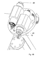
- FIG. 1B is to further explain the Figure 1A and most of the following exemplary embodiments show a more detailed illustration in which it can be seen that preferably two separate workpiece spindles are used, which are each designed as a compact unit and each have a separate electric motor with respective electrical connections 50.
- the right drawn Spindle carries the workpiece 48, which is drawn in engagement with the tool 19. Both spindles are each installed in a bearing block and form a so-called spindle unit.
- the storage blocks for the spindles are made in one piece with the spindle carrier, for example as a solid casting with correspondingly matching the spindle size exactly matching recesses.
- the associated drive control for the spindle movement preferably accelerates the spindle already at the beginning of the pivoting movement from the workpiece change zone into the processing space.
- the other spindle is preferably decelerated at the same time on the said spindle electric motor already at the beginning of the pivoting movement from the processing space into the workpiece change zone by operating the motor as a generator.
- the successive pivoting movements are preferably always in opposite directions, as in Fig. 17 shown to keep the cable routing for the electrical connections simple.
- the drive control for the swivel motor for the execution of the pivoting movement is preferably synchronized with the acceleration or deceleration of the spindle movements.
- Both drive controllers may be programmed controllers and implemented in a single software / hardware module or a combination.
- Such a control module 23 is together with control cables schematically with in Figure 1A located.
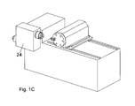
- the Figure 1C shows the embodiment Figure 1A with formed as a solid component spindle carrier 24 in the inter alia, the spindles used in it prepared precisely fitting recesses are embedded;
- the material for the spindle carrier is a sufficiently stable material such as aluminum, or stainless steel, or if it is to be operated in terms of weight optimization, also a high-strength plastic for use;
- FIG. 1D shows a front view Figure 1C with section line AA for FIG. 15 and BB for FIG. 16 ;
- the Figure 1E shows a plan view Figure 1C with cutting line CC for FIG. 17 ;
- FIG. 2 shows a further embodiment, in contrast to FIG. 1 the tool turret assembly is movable in the xz-plane in the xz-direction;
- FIG. 3 shows a further embodiment, wherein the pivot spindle according to the invention pivots about the x-axis and the pivot support is parallel to the xy plane, and the tool turret assembly in the yz plane is movable;
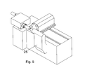
- FIG. 5 shows an embodiment according to FIG. 3 in which also such a tailstock 25 is provided
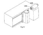
- FIG. 6 shows a further embodiment of a lathe according to the invention with a tool carriage which is movable in the xz plane and in which two workpiece spindles are provided on the spindle carrier, wherein the two spindle axes form a common axis, and wherein the pivot axis is in the x direction;
- the embodiment according to FIG. 6 Compared to the above-described embodiments, in particular, characterized in that the spindle support including housing has slightly smaller outer dimensions, since the spindles 20A and 20B are arranged in a particularly short design, but on a common axis.
- the electrical connections provided here are analogous in a similar way as in FIG. 17 shown.
- FIG. 7 shows a further embodiment, which is oriented relative to the figure in total and rotated 90 degrees in space, so that the tool turret assembly in the xy plane is movable.
- Such orientation of spindles and turrets may be advantageous in certain applications.
- FIG. 8 shows a further embodiment, in which, in contrast to the FIG. 6 the tool turret assembly is displaceable in the yz plane;
- FIG. 9 shows a further embodiment analogous to FIG. 8 however, rotated as a whole by 90 degrees;
- FIG. 10 shows a further embodiment in which the spindle carrier is mounted on an axis which extends in the y-direction and on both opposite sides of the spindle carrier has a support 28A, 28B on the frame of the lathe.
- the cable feeds may pass through the component forming the pivot axis, which may be hollow for this purpose.
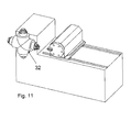
- FIG. 11 shows an embodiment in which a spindle support 32 is provided with four spindles, which are fixed in a cross arrangement on the spindle carrier, and wherein the pivoting movement extends about the y-axis, and wherein the tool turret assembly is movable in the y-direction in the z-direction and y-direction;
- FIG. 11 shown quadruple arrangement of spindles on a so-called cross-spindle carrier 32 gives much more opportunities to change the workpieces or re-clamp.
- the freshly machined workpiece can be removed.
- the work piece to be machined is used to the left and the work piece to be machined can be clamped in the upwardly pointing workpiece holder. This allows significantly greater freedom for virtually complete automation of the workpiece change.
- FIG. 12 shows a further embodiment, in which, as a modification to the embodiment of FIG. 2 not only a single side surface of the lathe frame is provided with spindle carrier and tool carriage, but also the opposite, parallel side surface is also provided with such an arrangement. Both arrangements are outlined by dashed lines for clarity.
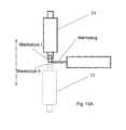
- FIG. 13A shows schematically and 13B shows in the simplified representation similar to the other preceding figures, another embodiment of a lathe according to the invention, in which the spindle carrier 21 carries two spindles whose axes coincide, but the spindle carrier 21 is not pivoted, but translationally in FIG. 13A is moved from the solid drawn, upper position in the dashed, lower position to bring the other spindle in the processing space;
- FIG. 13B is the workpiece spindle on its carrier 21 bidirectionally in the direction of the double arrow along a designated linear rail guide 34 movable.
- An optional CNC feed control of the tool for workpiece II - see FIG. 13A - Can be implemented almost identical to that for workpiece I, since it is kinematically just reversed.
- drive can also be resorted to prior art for translational movement, for example by servo motor as a traversing motor with gear and engaging in a movably mounted rack.
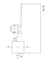
- FIG. 14 shows a schematic circuit diagram for the recovery of electrical current when braking a spindle:
- first couples the drives - see here the motors 51 and 52 for the fast and precise rotational movement of the tool turrets - via a DC-composite for example, this DC composite essentially becomes identical for each of the two motors formed electrical circuits of a series circuit of a frequency converter 53, a downstream of this custom power choke device 54, a conventional line filter 55 for eliminating noise and interference voltages, a contactor 56, and fuses 57 for each three-fold phases of a each electric motor 51 and 52 formed.
- the regenerated energy is delivered directly to other drive units.
- the surplus energy then still possibly is then fed via a feedback unit 58 in the network.
- a control unit 59 controls the Freufquenzumrichter 51.
- Another advantage is that the excess energy is not converted into heat and thus cooling units are not necessary or smaller in size.
- FIG. 15 shows the pivot spindle according to FIG. 1D schematically in section of the line AA of FIG. 1D ,
- FIG. 16 shows the pivot spindle schematically in section along the line BB in FIG. 1D .
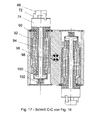
- Fig. 17 shows the pivot spindle schematically additionally in section along the line CC in Figure 1E ,
- two spindles 20A and 20B are installed with respective motors, which are supplied with electrical energy, compressed air and cooling water through a central opening 82 (lines not shown).
- the rotational movement of the spindle housing 24 takes place in this illustration by means of a servomotor - see motor 86 in FIG. 15 - with a pinion 106 and a ring gear, see ring gear 84 in FIG. 15 ,
- a servomotor - see motor 86 in FIG. 15 - with a pinion 106 and a ring gear, see ring gear 84 in FIG. 15
- the rotation angle of the housing 24 is detected and evaluated synchronously to the rotation electronically so that the spindle housing comes to a standstill at the right angle. Once this has been done, the spindle housing is blocked with a hydraulically actuated flat gear and positioned within the necessary repeatability.
- cooling channels 96 Still other elements of the system shown are shown as cooling channels 96, all of which are well known in the art.
- the necessary components are available as standard from manufacturers of tool turrets and so-called rotary indexing tables. This concerns in particular the drive motor with pinion and ring gear as well as the storage and indexing.
- the indexing is usually done by means of plan Hirth gears, but bolts o.ä. are also possible.
- Bearings are usually rolling bearings into consideration. But plain bearings and hydrostatic bearings can be used.
Landscapes
- Engineering & Computer Science (AREA)
- Mechanical Engineering (AREA)
- Turning (AREA)
Abstract
Description
Die vorliegende Erfindung betrifft das technische Gebiet der Werkzeugmaschinen der und insbesondere eine Drehmaschine nach dem Oberbegriff von Anspruch 1.The present invention relates to the technical field of machine tools, and more particularly to a lathe according to the preamble of
Drehmaschinen sind Werkzeugmaschinen, die zur Herstellung von meist runden Werkstücken durch Trennen des Werkstoffes vom Werkstück mit einer Schneide verwendet werden. Meist wird das Werkstück gedreht und ein nichtdrehendes Werkzeug mit der vorgenannten Schneide greift das Werkstück ein in einer spanabhebenden Bearbeitungsweise. An einer Drehmaschine werden Rotationskörper hergestellt, wobei Zusatzeinrichtungen vorhanden sein können, die es ermöglichen, auch Formen herzustellen, die nicht rotationsymmetrisch sind. Die Schnittbewegung wird dadurch vollzogen, dass das Werkstück rotiert während das Schneidwerkzeug fest auf einen Werkzeugschlitten gespannt ist und kontinuierlich spanabnehmend im Eingriff am Werkstück ist. Der das Werkzeug tragende Schlitten kann im Allgemeinen auf einer entsprechenden Führungsschiene längs und/oder quer zur Rotationsachse des Werkstücks entlang der zu bearbeitenden Fläche bewegt werden.Lathes are machine tools that are used for the production of mostly round workpieces by separating the material from the workpiece with a cutting edge. Usually, the workpiece is rotated and a non-rotating tool with the aforementioned blade engages the workpiece in a machining manner. Rotary bodies are produced on a lathe, and additional equipment may be present which makes it possible to produce shapes which are not rotationally symmetric. The cutting movement is accomplished by rotating the workpiece while the cutting tool is clamped tightly to a tool slide and is continuously cuttingly engaged on the workpiece. The carriage carrying the tool can generally be moved on a corresponding guide rail along and / or transverse to the axis of rotation of the workpiece along the surface to be machined.
Soll das Werkstück gewechselt werden, weil es fertig bearbeitet ist, muss die sich drehende Werkstückspindel angehalten werden, indem die Drehbewegung abgebremst wird, das Werkstück muss aus seiner Spannvorrichtung entfernt werden und ein neues Werkstück eingesetzt werden. Dann wird das neue Werkstück eingespannt, wobei meist eine Zentrierung automatisch erfolgt und die Drehbewegung wird wieder aufgenommen. Dann wird das Werkzeug wieder mit dem Werkstück in Eingriff gebracht und die weitere Bearbeitung kann erfolgen.If the workpiece is to be changed because it is finished, the rotating workpiece spindle must be stopped by slowing down the rotational movement, the workpiece must be removed from its fixture and a new workpiece inserted. Then the new workpiece is clamped, usually a centering is done automatically and the rotation is again added. Then the tool is again brought into engagement with the workpiece and the further processing can take place.
Für den Werkstückwechsel kann der Werkzeugrevolver aus einer Bearbeitungsposition in eine Werkstückwechselposition gefahren werden, damit der Werkstückwechsel leichter handhabbar ist.For the workpiece change, the tool turret can be moved from a processing position into a workpiece change position, so that the workpiece change is easier to handle.
Eine solche Drehmaschine ist in ihrem Gebrauch zwar zuverlässig, jedoch benötigt der Werkstückwechsel in nachteilhafter Weise eine zu lange Zeit. Dieser Nachteil wirkt sich umso gravierender aus, je kürzer die eigentliche Bearbeitungszeit des Werkstücks ist.While such a lathe is reliable in use, the workpiece change disadvantageously takes too long a time. This disadvantage is all the more serious, the shorter the actual machining time of the workpiece is.
Die so genannte "Span zu Span-Zeit" ist diejenige Zeit, während der keine Werkstückbearbeitung erfolgen kann, weil das Werkstück gewechselt wird.The so-called "span to span time" is the time during which no workpiece machining can take place because the workpiece is changed.
Daher besteht die Aufgabe der vorliegenden Erfindung darin, eine Bearbeitungsmaschine, insbesondere eine Drehmaschine derart weiterzubilden, dass die "Span-zu-Span-Zeitspanne" verringert wird.Therefore, the object of the present invention is to develop a processing machine, in particular a lathe, such that the "chip-to-chip period" is reduced.
Mit den Maßnahmen des unabhängigen Anspruches wird diese Aufgabe gelöst.With the measures of the independent claim this problem is solved.
In den Unteransprüchen sind vorteilhafte Ausgestaltungen Weiterbildungen und Verbesserungen des jeweiligen Gegenstandes der Erfindung angegeben.In the dependent claims advantageous refinements developments and improvements of the respective subject of the invention are given.
Kurz zusammengefasst enthält die vorliegende Erfindung die Idee, an der die Werkstückspindel tragenden Einheit nicht nur eine einzige Werkstückspindel anzubringen, sondern eine Mehrzahl davon, bevorzugt zwei Werkstückspindeln. Die beiden Werkstückspindeln sind im wesentlichen voneinander unabhängig und so angebracht, dass die zweite Werkstückspindel den Bearbeitungsvorgang nicht stört, der mit der ersten Werkstückspindel gerade ausgeführt wird.Briefly summarized, the present invention includes the idea of attaching not only a single workpiece spindle to the unit bearing the workpiece spindle, but a Plurality thereof, preferably two workpiece spindles. The two workpiece spindles are substantially independent of each other and mounted so that the second workpiece spindle does not interfere with the machining process that is being performed with the first workpiece spindle.
Beide Spindeln sind mit Werkstückspannmitteln ausgerüstet, wie sie im Stand der Technik bekannt sind. Erfindungsgemäß ist die Anordnung der beiden Werkstückspindeln an einer gemeinsamen Verfahreinheit derart, dass, während eine von den beiden Spindeln mit einem Werkstück im Bearbeitungsraum den Bearbeitungsprozess durchläuft, an der zweiten Spindel gleichzeitig zum Bearbeitungsprozess, aber außerhalb des Bearbeitungsraumes ein Ent- und Beladen des Werkstückes erfolgen kann. Diese Be- und Entladung der jeweils nicht zur Werkstückbearbeitung benötigten Werkstückspindel kann manuell vom Bediener der Maschine oder auch automatisch durchgeführt werden. Dabei kann entweder ein neues, rohes, unbearbeitetes Werkstück eingespannt werden oder ein bereits bearbeitetes Werkstück kann in einer anderen Position eingespannt werden, damit es entsprechend neu bearbeitet werden kann. Die Verfahrbewegung der Spindelträgereinheit ist vorzugsweise eine Schwenkbewegung, sie kann aber auch eine translatorische Bewegung sein.Both spindles are equipped with workpiece clamping means, as are known in the art. According to the arrangement of the two workpiece spindles on a common moving part is such that, while one of the two spindles with a workpiece in the processing room passes through the machining process, on the second spindle simultaneously to the machining process, but outside of the processing space carried out a loading and unloading of the workpiece can. This loading and unloading of each required for workpiece machining workpiece spindle can be done manually by the operator of the machine or automatically. In this case, either a new, raw, unprocessed workpiece can be clamped or an already machined workpiece can be clamped in another position so that it can be reworked accordingly. The movement of the spindle carrier unit is preferably a pivoting movement, but it can also be a translational movement.
Die oben genannte, kritische und gering zu haltende "Span zu Span-Zeit" wird erfindungsgemäß daher im Wesentlichen allein von dem Verfahr- oder Schwenkvorgang der beiden Spindeln bestimmt. Dabei ist die Bewegung in bevorzugter Weise so definiert, dass es lediglich zwei Stellungen gibt, dass also in jeder der beiden Endstellungen der Bewegung jeweils ein Werkstück mit dem Werkzeug in Eingriff gebracht werden kann.The above-mentioned, critical and low-maintenance "chip-to-chip time" is therefore determined according to the invention essentially solely by the traversing or pivoting process of the two spindles. In this case, the movement is preferably defined so that there are only two positions, so that in each of the two end positions of the movement in each case a workpiece can be brought into engagement with the tool.
In vorteilhafter Weise kann daher der komplexe und fehleranfällige Vorgang des Einspannens des Werkstücks deutlich sorgfältiger und im Prinzip ohne Zeitverlust durchgeführt werden, denn er wird ja während der Bearbeitungszeit des jeweils anderen Werkstückes durchgeführt, wodurch man keinerlei Zeitverlust hinnehmen muss.Advantageously, therefore, the complex and error-prone process of clamping the workpiece clearly Careful and in principle without loss of time to be carried out, because it is so carried out during the processing time of the other workpiece, so you have to take any time loss.
In vorteilhafter Weise ist nur eine einzige Antriebselektronik vorgesehen, die dann jeweils dazu wechselweise benutzt werden kann, um die Werkstückspindel in Drehbewegung zu versetzen. Es findet dabei also jeweils ein aktives Umschalten des Antriebs von der einen Werkstückspindel auf die andere statt.Advantageously, only a single drive electronics is provided, which can then each be used alternately to enable the workpiece spindle in rotary motion. Thus, in each case an active switching of the drive from one workpiece spindle to the other takes place.
In vorteilhafter Weise kann die Bewegungsenergie der ersten Spindel beim Abbremsen durch die Brems- Induktionswirkung des dann als Generator benutzten Elektromotors in das Netz zurückgespeist werden und zumindest teilweise zur Beschleunigung der zweiten Spindel benutzt werden. Dies erhöht die Energieeffizienz der erfindungsgemäßen Drehmaschine.Advantageously, the kinetic energy of the first spindle during braking by the brake induction effect of the then used as a generator electric motor can be fed back into the network and at least partially used to accelerate the second spindle. This increases the energy efficiency of the lathe according to the invention.
Die erfindungsgemäße Schwenkspindelanordnung mit zwei unabhängigen Werkstückspindeln kann jeweils auch mit einem Reitstock verwendet werden, um das Werkstück gezielt zu unterstützen. Hierzu wird auf den einschlägigen Stand der Technik verwiesen.The pivoting spindle assembly according to the invention with two independent workpiece spindles can each also be used with a tailstock in order to specifically support the workpiece. Reference is made to the relevant prior art.
Das der Erfindung zugrunde liegende Prinzip der gleichzeitigen Be- und Entladung eines Werkstücks mit der Bearbeitung eines anderen Werkstücks kann auch insofern erweitert werden, indem nicht nur zwei, sondern gegebenenfalls drei oder vier, ganz allgemein mehrere Werkstückspindeln auf einer gemeinsamen Schwenkeinheit vorgesehen sind. Dies kann sich insbesondere dann empfehlen, wenn eine komplexere Bearbeitung der Werkstücke mit unterschiedlichen Einspannlokationen derselben Werkstücke in einer entsprechend mehrstufigen Bearbeitungsweise erforderlich ist, und/ oder wenn ein gewisser Puffer an fertig vorbereiteten und eingespannten Werkstücken vorhanden sein sollte, um eine möglichst hohe Produktionsrate an fertigen Werkstücken zu erzielen.The principle underlying the invention of the simultaneous loading and unloading of a workpiece with the machining of another workpiece can also be extended insofar as not only two, but optionally three or four, quite generally several workpiece spindles are provided on a common pivot unit. This can be particularly recommended when a more complex machining of the workpieces with different Einspannlokationen the same workpieces in a corresponding multi-stage processing is required, and / or if a certain buffer ready prepared and clamped Workpieces should be present in order to achieve the highest possible production rate of finished workpieces.
Die Anordnung des Spindelstocks oder Spindelträgers, der wenigstens zwei Werkstückspindeln trägt, am Gestell der Drehmaschine sowie die relative Orientierung des Schwenkspindelstocks zum Werkzeugschlitten und dessen linearer Richtung kann vielfach modifiziert werden. Die in den Zeichnungen gezeigten Beispiele sollen einige dieser möglichen Variationen veranschaulichen.The arrangement of the headstock or spindle carrier, which carries at least two workpiece spindles on the frame of the lathe and the relative orientation of the pivoting spindle stock to the tool carriage and its linear direction can be modified many times. The examples shown in the drawings are intended to illustrate some of these possible variations.
Anhand der Zeichnungen werden Ausführungsbeispiele der Erfindung erläutert.With reference to the drawings, embodiments of the invention will be explained.
Es zeigen:
-
Figur 1A zeigt ein erstes Ausführungsbeispiel einer erfindungsgemäßen Drehmaschine mit zwei Spindeln, die auf einem Spindelträger befestigt sind, wobei der Spindelträger in der x-z-Ebene liegt, und wobei die Schwenkachse zum Verschwenken der beiden Spindeln in y-Richtung liegt, und wobei ein Flachbett für zwei übereinander angeordnete Schlitten in der y-z-Ebene vorhanden ist, wobei der untere Schlitten in z- Richtung und der obere in y- Richtung verfahrbar ist und der Aufbau auf dem oberen Schlitten aus Werkzeugrevolver samt Antrieb und Lagerung des Revolvers somit in y- und z-Richtung verfahrbar ist; -
Figur 1B zeigt eine vergrößerte Ausschnittsdarstellung eines Ausführungsbeispiels der erfindungsgemäßen Drehmaschine mit Schwenkspindel, bei der auch die Anordnung der elektrischen Anschlüsse und Details des Bearbeitungsraumes genauer gezeigt sind; -
Figur 1C zeigt das Ausführungsbeispiel ausFigur 1A mit als massives Bauteil gebildetem Spindelträger in den unter anderem die Spindeln eingesetzt sind; -
Figur 1D zeigt eine Vorderansicht zuFigur 1C mit Schnittlinie A-A fürFigur 15Figur 16 -
Figur 1E zeigt eine Draufsicht zuFigur 1C mit Schnittlinie C-C fürFigur 17 -
Figur 2 zeigt ein weiteres Ausführungsbeispiel, wobei im Gegensatz zuFigur 1 -
Figur 3 zeigt ein weiteres Ausführungsbeispiel, wobei die erfindungsgemäße Schwenkspindel um die x-Achse verschwenkt und der Schwenkträger parallel zur x-y-Ebene liegt, und der Werkzeugrevolveraufbau in der y-z-Ebene in y- und z-Richtung verfahrbar ist; -
Figur 4 zeigt ein weiteres Ausführungsbeispiel gemäß denFiguren 1A ,1B , wobei ein Reitstock zum Abstützen des freien Endes eines eingespannten Werkstücks vorgesehen ist; -
Figur 5 zeigt ein Ausführungsbeispiel gemäßFigur 3 , bei dem ebenfalls ein solcher Reitstock vorgesehen ist; -
Figur 6 zeigt ein weiteres Ausführungsbeispiel einer erfindungsgemäßen Drehmaschine mit einem Werkzeugrevolveraufbau, der in der x-z-Ebene in x- und z-Richtung verfahrbar ist und bei dem auf dem Spindelträger zwei Werkstückspindeln vorgesehen sind, wobei deren beider Spindelachsen eine gemeinsame Achse bilden, und wobei die Schwenkachse in x-Richtung liegt; -
Figur 7 zeigt ein weiteres Ausführungsbeispiel, das gegenüber dem ausFigur 6 insgesamt um 90 Grad gedreht im Raum orientiert ist, so dass der Werkzeugrevolveraufbau in der y-z-Ebene in y- und z-Richtung verfahrbar ist; -
Figur 8 zeigt ein weiteres Ausführungsbeispiel, bei dem in Abwandlung zu dem Beispiel ausFigur 6 der Werkzeugrevolveraufbau in der y-z-Ebene in y- und z-Richtung verfahrbar ist; -
Figur 9 zeigt ein weiteres Ausführungsbeispiel analog zuFigur 8 , das jedoch als Ganzes um 90 Grad gedreht ist; -
Figur 10 -
Figur 11 zeigt ein Ausführungsbeispiel, bei dem ein Spindelträger mit vier Spindeln vorgesehen ist, die einer Kreuzanordnung am Spindelträger befestigt sind, und wobei die Schwenkbewegung um die y-Achse verläuft und wobei der Werkzeugrevolveraufbau in der y-z-Ebene in y- und z-Richtung verfahrbar ist; -
Figur 12Figur 2 nicht nur eine einzige Seitenfläche des Drehmaschinengestells mit Spindelträger und Werkzeugschlitten versehen ist, sondern auch die gegenüberliegenden, dazu parallele Seitenfläche ebenfalls mit einer solchen Anordnung versehen ist; -
Figur 13A in einer schematischen Darstellung undFigur 13B in einer etwas vereinfachenden Darstellung zeigen ein weiteres Ausführungsbeispiel einer erfindungsgemäßen Drehmaschine, bei der der Spindelträger zwei Spindeln trägt, deren Achsen übereinstimmen, wobei aber der Spindelträger nicht verschwenkt wird, sondern translatorisch bewegt wird, um die jeweils andere Spindel in den Bearbeitungsraum zu bringen; -
Figur 14 -
Figur 15Figur 1D ; -
Figur 16Figur 1D ; -
Figur 17Figur 1E ;
-
Figure 1A shows a first embodiment of a lathe according to the invention with two spindles which are mounted on a spindle carrier, wherein the spindle carrier is in the xz plane, and wherein the pivot axis for pivoting the two spindles in the y-direction, and wherein a flat bed for two one above the other arranged slide in the yz plane is present, the lower carriage in the z direction and the upper in the y direction is moved and the structure on the upper slide tool turret including drive and storage of the revolver thus in the y and z direction is movable; -
FIG. 1B shows an enlarged sectional view of an embodiment of the rotating machine according to the invention with a pivot spindle, in which the arrangement of the electrical connections and details of the processing space are shown in more detail; -
Figure 1C shows the embodimentFigure 1A with formed as a solid component spindle carrier in the inter alia, the spindles are used; -
FIG. 1D shows a front viewFigure 1C with section line AA forFIG. 15 as well as cutting line BB forFIG. 16 ; -
Figure 1E shows a plan viewFigure 1C with cutting line CC forFIG. 17 ; -
FIG. 2 shows a further embodiment, in contrast toFIG. 1 the tool turret assembly is movable in the x and z direction in the xz plane; -
FIG. 3 shows a further embodiment, wherein the pivot spindle according to the invention pivots about the x-axis and the pivot support is parallel to the xy plane, and the tool turret structure in the yz plane in the y- and z-direction is movable; -
FIG. 4 shows a further embodiment according to theFigures 1A .1B wherein a tailstock for supporting the free end of a clamped workpiece is provided; -
FIG. 5 shows an embodiment according toFIG. 3 in which also such a tailstock is provided; -
FIG. 6 shows a further embodiment of a lathe according to the invention with a tool turret assembly which is movable in the xz plane in the x and z directions and in which two workpiece spindles are provided on the spindle carrier, wherein the two spindle axes form a common axis, and wherein the pivot axis lies in the x direction; -
FIG. 7 shows a further embodiment, opposite to theFIG. 6 rotated in total 90 degrees in space is oriented so that the tool turret assembly in the yz plane in the y and z directions can be moved; -
FIG. 8 shows a further embodiment, in which, in a modification to the exampleFIG. 6 the tool turret structure is movable in the yz plane in the y and z directions; -
FIG. 9 shows a further embodiment analogous toFIG. 8 however, rotated as a whole by 90 degrees; -
FIG. 10 shows a further embodiment in which the spindle carrier is mounted on an axis which extends in the y-direction and on both opposite sides of the spindle carrier has a support on the frame of the lathe, wherein a chip conveyor is provided; -
FIG. 11 shows an embodiment in which a spindle support is provided with four spindles, which are fixed to a cross assembly on the spindle carrier, and wherein the pivoting movement about the y-axis and wherein the tool turret assembly in the yz plane in the y- and z-direction is movable ; -
FIG. 12 shows a further embodiment, in which, as a modification to the embodiment ofFIG. 2 not only a single side surface of the lathe frame is provided with spindle carrier and tool carriage, but also the opposite, parallel side surface is also provided with such an arrangement; -
FIG. 13A in a schematic representation andFIG. 13B in a somewhat simplistic view, another embodiment of a lathe according to the invention, in which the spindle carrier carries two spindles whose axes coincide, but wherein the spindle carrier is not pivoted, but is moved translationally to bring the other spindle in the processing space; -
FIG. 14 shows a schematic circuit diagram for the recovery of electric current when braking a spindle; -
FIG. 15 shows a first sectional view along the line AA of the embodiment according to FIGFIG. 1D ; -
FIG. 16 shows a second sectional view of the line BBFIG. 1D ; -
FIG. 17 shows a third sectional view along the line CC of the embodiment according toFigure 1E ;
In den Figuren bezeichnen gleiche Bezugszeichen gleiche oder funktionsgleiche Komponenten. Zunächst wird auf
Das Gestell 12 einer erfindungsgemäßen Drehmaschine 10 besteht aus einem quaderförmigen Grundkörper, derdas Maschinenbett 14 beinhaltet und auf dessen Oberfläche der Werkzeugschlitten 16 gemäß Stand der Technik eingerichtet ist.Das Gestell 12 enthält weiter einen quaderförmigen Aufsatz am links dargestellten Ende des quaderförmigen Grundkörpers, wobei der Aufsatz eine nicht dargestellte Aufnahme für die Schwenkachse eines Spindelträgers 21 enthält.Der Spindelträger 21 besitzt eine Achse, die mit einem Elektromotor (nicht dargestellt) verbunden ist, der im Innern des Aufsatzes 17 befindlich ist. Der Elektromotor kann erfindungsgemäß so angesteuert werden, dass der erfindungsgemäße Schwenkspindelträger mit seinen beiden darauffest montierten Spindeln ist mit Bezugszeichen 15 schematisch angedeutet.
- The
frame 12 of alathe 10 according to the invention consists of a cuboid base body, which includes themachine bed 14 and on the surface of thetool carriage 16 is arranged according to the prior art. - The
frame 12 further includes a cuboid attachment at the left end of the cuboid base body, wherein the attachment contains a receptacle, not shown, for the pivot axis of aspindle carrier 21. Thespindle carrier 21 has an axis which is connected to an electric motor (not shown) located in the interior of theattachment 17. The electric motor according to the invention can be controlled so that the inventive Pivot spindle carrier with its twospindles tool 19. The processing space is indicated schematically byreference numeral 15.
Das Werkzeug 19 ist wie im Stand der Technik üblich an einem Werkzeugrevolver mittels einer Einspanneinrichtung fixiert und kann über eine Bewegung des Schlittens 16 in Eingriff mit dem Werkstück gebracht werden. Das Werkzeug ist auf dem Schlitten seinerseits in y-Richtung und der Schlitten selbst in z-Richtung in jeweiligen Schienenführungen verfahrbar. Die zugehörigen Antriebe sind aus dem Stand der Technik bekannt. Hier können zweckmäßigerweise elektrische Servomotoren, Linearmotoren oder Schrittmotoren, verwendet werden.The
Der oben genannte Vorteil, das ein Werkstückwechsel oder ein Neueinspannen des gleichen Werkstücks während der Bearbeitung eines anderen Werkstücks stattfinden kann, wird dem Durchschnittsfachmann aufgrund der Schwenkmöglichkeit des Spindelträgers und dem gleichzeitigen Vorhandensein von zwei, praktisch identischen Werkstückspindeln unmittelbar klar, denn die zweite Werkstückspindel 20B kann ja in der Bearbeitungszeit für das Werkstück von Spindel 20A be- oder entladen werden. Daher nimmt ein Werkstückwechsel oder ein Umspannen des alten Werkstücks praktisch keine zusätzliche Zeit zur Bearbeitungszeit in Anspruch.The aforesaid advantage that workpiece replacement or relocking of the same workpiece may occur during machining of another workpiece will become immediately apparent to those of ordinary skill in the art because of the pivoting capability of the spindle carrier and the simultaneous presence of two virtually identical workpiece spindles, since the
Die möglichst schnelle und präzise geführte Drehbewegung der Schwenkspindel geschieht in vorteilhafter Weise mit Hilfe eines elektronisch gesteuerten Servomotors, der über eine separate Programmschnittstelle programmiert werden kann. Er vollführt in vorteilhafter Weise eine Drehbewegung um 180 Grad in der einen Richtung, und dann wieder eine Drehbewegung zurück um 180 Grad in die entgegen gesetzte Richtung. Auf diese Weise kann vermieden werden, dass eventuell vorhandene Kabelführungen oder Wasser- oder Luftführungen, deren eines Ende jeweils an einem drehbewegten Teil hängt und dessen anderes Ende an einem festen Teil hängt, sich unbegrenzt oft um die Schwenkachse wickeln würde. Dies gilt es im Hinblick auf eine technisch einfache und robuste Bauweise zu vermeiden. Wenn dies eine untergeordnete Rolle spielen sollte, können auch im Stand der Technik bekannte Drehdurchführungen für Luft oder Wasser und Schleifringe oder drahtlose elektrische Verbindungen soweit wie möglich verwendet werden. Als Schwenkantrieb sind auch pneumatische oder hydraulische Antriebe verwendbar.The fastest possible and precisely guided rotational movement of the pivot spindle is done in an advantageous manner by means of an electronically controlled servomotor, which can be programmed via a separate program interface. He performs advantageously a rotational movement 180 degrees in one direction, and then a turn back 180 degrees in the opposite direction. In this way it can be avoided that any existing cable guides or water or air ducts, one end of each hanging on a rotating part and the other end depends on a fixed part, would indefinitely wrap around the pivot axis. This is to be avoided in view of a technically simple and robust construction. If this should be of minor importance, air or water rotary unions known from the prior art and slip rings or wireless electrical connections can be used as much as possible. As a rotary actuator and pneumatic or hydraulic actuators are used.
Über ein im Stand der Technik bekanntes Mess- und Steuersystem wird bei der Drehung oder der Schwenkbewegung des Spindelgehäuses bzw. Spindelträgers der Drehwinkel / Schwenkwinkel erfasst und ausgewertet, und der Motor für die Schwenkbewegung des Spindelgehäuses entsprechend angesteuert, damit dieses im richtigen Winkel zum Stillstand kommen kann. Die Drehbewegung des Spindelgehäuses erfolgt in dieser Darstellung mittels Servomotor mit Ritzel und Zahnkranz. Ist das Gehäuse zum Stillstand gekommen, wird das Spindelgehäuse mit einer hydraulisch betätigten Planverzahnung blockiert und in der notwendigen Wiederholgenauigkeit positioniert, die sogenannte Indexierung der Spindeln kann also auf diese Weise erfolgen.About a well-known in the art measuring and control system, the rotation angle / tilt angle is detected and evaluated during rotation or pivotal movement of the spindle housing or spindle support, and the motor for the pivotal movement of the spindle housing driven accordingly so that this come to a standstill at the right angle can. The rotational movement of the spindle housing takes place in this illustration by means of a servo motor with pinion and ring gear. If the housing has come to a standstill, the spindle housing is blocked with a hydraulically operated planer teeth and positioned in the necessary repeatability, so the so-called indexing of the spindles can be done in this way.
Gemäß
Die Kopplungen beider Spindeln zu einer gemeinsam vorgesehenen Antriebssteuerung erfolgt jeweils separat, ist aber in
Die zugehörige Antriebssteuerung für die Spindelbewegung beschleunigt die Spindel bevorzugt bereits zu Beginn der Schwenkbewegung aus der Werkstückwechselzone in den Bearbeitungsraum. Analog dazu wird bevorzugt die andere Spindel zeitgleich über den genannten Spindel-Elektromotor bereits zu Beginn der Schwenkbewegung aus dem Bearbeitungsraum in die Werkstückwechselzone abgebremst, indem man den Motor als Generator betreibt. Die aufeinander folgenden Schwenkbewegungen sind bevorzugt immer gegensinnig, wie in
Die Antriebssteuerung für den Schwenkmotor für die Ausführung der Schwenkbewegung erfolgt bevorzugt synchronisiert mit der Beschleunigung bzw. Abbremsung der Spindelbewegungen. Beide Antriebssteuerungen können programmierte Steuerungen sein, und in einem einzigen Software-/ Hardwaremodul oder einer Kombination implementiert sein. Ein solches Steuermodul 23 ist samt Steuerkabeln schematisch mit in
Die
Die
Die
Die
Die
Die
Die
Die Ausführungsform gemäß
Die
Durch die erfindungsgemäße, in
Das in
Als Antrieb kann ebenfalls auf Stand der Technik zur translatorischen Bewegung zurückgegriffen werden, beispielsweise per Servomotor als Verfahrmotor mit Zahnrad und Eingriff in eine beweglich gelagerte Zahnstange.As drive can also be resorted to prior art for translational movement, for example by servo motor as a traversing motor with gear and engaging in a movably mounted rack.
So wird die generatorisch erzeugte Energie direkt an andere Antriebseinheiten abgegeben. Die dann noch eventuell vorhandene überschüssige Energie wird dann über eine Rückspeiseeinheit 58 in das Netz eingespeist. Eine Steuereinheit 59 steuert die Freuquenzumrichter 51 an.Thus, the regenerated energy is delivered directly to other drive units. The surplus energy then still possibly is then fed via a
Auch eine DC-Kopplung ohne Rückspeiseeinheit 58 ist sinnvoll, weil auch so ebenfalls erheblich Energie eingespart werden kann.Even a DC coupling without
Diese Anwendungen sind im Stand der Technik an sich bekannt und werden bereits in der Stahl und Textilindustrie eingesetzt.These applications are known per se in the art and are already used in the steel and textile industry.
Ein weiterer Vorteil ist, dass die überschüssige Energie nicht in Wärme umgewandelt wird und somit Kühlaggregate nicht oder in kleinerer Ausführung notwendig sind.Another advantage is that the excess energy is not converted into heat and thus cooling units are not necessary or smaller in size.
Weitere Kosten werden reduziert, da der Spitzenverbrauchswert vermindert wird, was ein wesentlicher Faktor für die Berechnung des Energieversorgers ist.Further costs are reduced because the peak consumption value is reduced, which is a significant factor in the calculation of the energy supplier.
In dem drehbar gelagertem Spindelgehäuse 24 sind zwei Spindeln 20A und 20B mit jeweiligen Motoren eingebaut, die durch eine zentrale Öffnung 82 (Leitungen nicht dargestellt) mit elektrischer Energie, Druckluft und Kühlwasser versorgt werden.In the rotatably mounted
Die Drehbewegung des Spindelgehäuses 24 erfolgt in dieser Darstellung mittels eines Servomotors -siehe Motor 86 in
In
Der Fachmann erkennt, dass die Schwenkspindelanordnung im Prinzip dadurch hergestellt werden kann, dass auf einem schwenkbar gelagerten und mit einem Schwenkantrieb versehenen "Schwenktisch" nur die beiden Motordrehspindeln aufgesetzt und dort an der richtigen Stelle fixiert werden müssen, damit mit der erforderlichen Genauigkeit die Werkstücke der beiden Spindeln jeweils an dem identischen Bearbeitungsort befindlich sind.The skilled artisan recognizes that the swivel spindle assembly can in principle be prepared by the fact that mounted on a pivotally mounted and provided with a swivel drive "swing table" only the two motor spindles and fixed there in the right place, so with the required accuracy, the workpieces of two spindles are each located at the same processing location.
Folgende Hersteller kommen unter anderen für die folgenden Elemente der erfindungsgemäßen Drehmaschine beispielsweise in Frage:
- Spindeln:
- Fa. Weiss, 97424 Schweinfurt, Fa. GMN, 90411 Nürnberg, Fa. Diebold, 72417 Jungingen, Fa. Hugo Reckert, 70794 Filderstadt, Fa. TS Technologie&Service, 97440 Werneck, Fa. SPL Spindel und Präzisionslager, 08427 Fraureuth.
- Drehfutter:
- Fa. Röhm, 89567 Sontheim, Fa. Schunk, 74348 Lauffen, Fa. Kitagawa (Japan), erhältlich von H. Sartorius Nachf. GmbH & Co.KG, 40837 Ratingen, Fa. SMW Autoblok, 88074 Meckenbeuren.
- Werkzeugrevolver:
- Fa. Sauter, 72555 Metzingen, Fa. Zeisberg, 65719 Hofheim.
- Rundschalttische:
- Fa. Fibro, 74189 Weinsberg, Fa. Weiss, 97424 Schweinfurt.
- spindles:
- Fa. Weiss, 97424 Schweinfurt, GMN, 90411 Nuremberg, Fa. Diebold, 72417 Jungingen, Fa. Hugo Reckert, 70794 Filderstadt, Fa. TS Technology & Service, 97440 Werneck, Fa. SPL spindle and precision bearings, 08427 Fraureuth.
- Chucks:
- Rohm, 89567 Sontheim, Schunk, 74348 Lauffen, Kitagawa (Japan), available from H. Sartorius Nachf. GmbH & Co. KG, 40837 Ratingen, Fa. SMW Autoblok, 88074 Meckenbeuren.
- Turret:
- Fa. Sauter, 72555 Metzingen, Fa. Zeisberg, 65719 Hofheim.
- Indexing tables:
- Fa. Fibro, 74189 Weinsberg, Fa. Weiss, 97424 Schweinfurt.
Für das Verschwenken der Spindelbox sind die notwendigen Bauteile im Standardangebot von Herstellern von Werkzeugrevolvern und sogenannten Rundschalttischen erhältlich. Das betrifft im Besonderen den Antriebmotor mit Ritzel und Zahnkranz ebenso die Lagerung und die Indexierung.For the pivoting of the spindle box, the necessary components are available as standard from manufacturers of tool turrets and so-called rotary indexing tables. This concerns in particular the drive motor with pinion and ring gear as well as the storage and indexing.
Die Indexierung erfolgt meist mittels über Plan- Hirthverzahnungen, aber Bolzen o.ä. sind ebenso möglich. Als Lagerung kommen meist Wälzlager in Betracht. Aber auch Gleitlager und hydrostatische Lager können eingesetzt werden.The indexing is usually done by means of plan Hirth gears, but bolts o.ä. are also possible. Bearings are usually rolling bearings into consideration. But plain bearings and hydrostatic bearings can be used.
Obwohl die vorliegende Erfindung anhand eines bevorzugten Ausführungsbeispiels vorstehend beschrieben wurde, ist sie darauf nicht beschränkt, sondern auf vielfältige Weise modifizierbar.Although the present invention has been described above with reference to a preferred embodiment, it is not limited thereto, but can be modified in a variety of ways.
Schließlich können die Merkmale der Unteransprüche und des Hauptanspruchs im wesentlichen frei miteinander und nicht durch die in den Ansprüchen vorliegende Reihenfolge miteinander kombiniert werden, sofern sie unabhängig voneinander sind.Finally, the features of the subclaims and the main claim may be essentially free with each other and not are combined by the order given in the claims if they are independent of each other.
- 1010
- Drehmaschinelathe
- 1212
- Gestellframe
- 1414
- Maschinenbettmachine bed
- 1515
- Bearbeitungsraumworking space
- 1616
- Werkzeugschlittentool slide
- 1717
- Aufsatzessay
- 1818
- Werkzeugrevolvertool turret
- 1919
- WerkzeugTool
- 20A20A
- Werkstückspindel im BearbeitungsraumWorkpiece spindle in the processing room
- 20B20B
- Werkstückspindel in dem Entladeraum für Werkstückwech-selWorkpiece spindle in the unloading space for workpiece change
- 2121
- Spindelträgerspindle carrier
- 2222
- Spannmittel zum Einspannen des WerkstücksClamping device for clamping the workpiece
- 2323
- Steuermodulcontrol module
- 2424
- SpindelträgergehäuseSpindle support housing
- 2525
- Reitstocktailstock
- 2626
- Spindelträger mit AbstandhalterSpindle carrier with spacer
- 28A,28A,
- 28B Seitenwange mit Auflager28B side bolster with support
- 3030
- Spänefördererchip conveyor
- 3232
- 4-fach Kreuzspindelträger4-fold crosshead carrier
- 3434
- lineare Schienenführunglinear rail guide
- 4848
- Werkstückworkpiece
- 5050
- elektrische Anschlüsse für Motor und Steuerung der An- triebselektronikelectrical connections for the motor and control of the drive electronics
- 7272
- Spannbackenjaws
- 7474
- DrehfutterChucks
- 7676
- Planverzahnungcrown gear
- 7878
- Axiallagerthrust
- 8080
- Radiallagerradial bearings
- 8282
- Durchführungsöffnung für Strom, Wasser, etc.Passage opening for electricity, water, etc.
- 8484
- Zahnkranzsprocket
- 8686
- Servomotorservomotor
- 8888
- Maschinenbettmachine bed
- 9090
- Spindellagerspindle bearings
- 9292
- Rotorrotor
- 9494
- Statorstator
- 9696
- Kühlkanälecooling channels
- 9898
- Versorgungsleitungensupply lines
- 100100
- Spannzylinderclamping cylinder
- 102102
- Messsystemmeasuring system
- 106106
- Ritzelpinion
Claims (7)
mit einer DC-Kopplungsschaltung, die die beiden Antriebsstränge für Drehbewegung der Mehrzahl von Werkzeugspindeln (20) in einem Gleichstromverbund miteinander koppelt,
und mit einem Rückspeisemodul (58) zum zumindest teilweisen Rück-Einspeisen von elektrischer Energie in das Stromversorgungsnetz.Lathe according to one of the preceding claims, comprising a control circuit (23) which is switchably arranged for one of the electric motors to be operated as a generator for the purpose of braking an associated spindle,
a DC coupling circuit coupling the two drive trains for rotational movement of the plurality of tool spindles (20) in a DC composite,
and with a regenerative module (58) for at least partial Re-feeding electrical energy into the power grid.
Priority Applications (2)
| Application Number | Priority Date | Filing Date | Title |
|---|---|---|---|
| AT09008991T ATE511426T1 (en) | 2009-07-09 | 2009-07-09 | LATHE WITH TWO WORKPIECE SPINDLES |
| EP09008991A EP2272624B1 (en) | 2009-07-09 | 2009-07-09 | Lathe with two workpiece spindles |
Applications Claiming Priority (1)
| Application Number | Priority Date | Filing Date | Title |
|---|---|---|---|
| EP09008991A EP2272624B1 (en) | 2009-07-09 | 2009-07-09 | Lathe with two workpiece spindles |
Publications (2)
| Publication Number | Publication Date |
|---|---|
| EP2272624A1 true EP2272624A1 (en) | 2011-01-12 |
| EP2272624B1 EP2272624B1 (en) | 2011-06-01 |
Family
ID=41416105
Family Applications (1)
| Application Number | Title | Priority Date | Filing Date |
|---|---|---|---|
| EP09008991A Active EP2272624B1 (en) | 2009-07-09 | 2009-07-09 | Lathe with two workpiece spindles |
Country Status (2)
| Country | Link |
|---|---|
| EP (1) | EP2272624B1 (en) |
| AT (1) | ATE511426T1 (en) |
Cited By (2)
| Publication number | Priority date | Publication date | Assignee | Title |
|---|---|---|---|---|
| JP2014507293A (en) * | 2011-01-26 | 2014-03-27 | ヴァルター マシーネンバウ ゲーエムベーハー | Machine for workpiece machining and / or measurement with two pivotable transverse members |
| CN108480727A (en) * | 2018-04-27 | 2018-09-04 | 安陆市天星粮油机械设备有限公司 | A kind of milling machine for processing pressing screw |
Citations (3)
| Publication number | Priority date | Publication date | Assignee | Title |
|---|---|---|---|---|
| AT264965B (en) | 1965-05-13 | 1968-09-25 | Gildemeister Werkzeugmasch | Lathe |
| GB1273505A (en) * | 1969-02-14 | 1972-05-10 | Monforts Fa A | Improvements in or relating to lathes |
| US5514061A (en) * | 1993-07-26 | 1996-05-07 | Okuma Corporation | Machine tool for working rear surface of workpiece |
-
2009
- 2009-07-09 AT AT09008991T patent/ATE511426T1/en active
- 2009-07-09 EP EP09008991A patent/EP2272624B1/en active Active
Patent Citations (3)
| Publication number | Priority date | Publication date | Assignee | Title |
|---|---|---|---|---|
| AT264965B (en) | 1965-05-13 | 1968-09-25 | Gildemeister Werkzeugmasch | Lathe |
| GB1273505A (en) * | 1969-02-14 | 1972-05-10 | Monforts Fa A | Improvements in or relating to lathes |
| US5514061A (en) * | 1993-07-26 | 1996-05-07 | Okuma Corporation | Machine tool for working rear surface of workpiece |
Cited By (2)
| Publication number | Priority date | Publication date | Assignee | Title |
|---|---|---|---|---|
| JP2014507293A (en) * | 2011-01-26 | 2014-03-27 | ヴァルター マシーネンバウ ゲーエムベーハー | Machine for workpiece machining and / or measurement with two pivotable transverse members |
| CN108480727A (en) * | 2018-04-27 | 2018-09-04 | 安陆市天星粮油机械设备有限公司 | A kind of milling machine for processing pressing screw |
Also Published As
| Publication number | Publication date |
|---|---|
| EP2272624B1 (en) | 2011-06-01 |
| ATE511426T1 (en) | 2011-06-15 |
Similar Documents
| Publication | Publication Date | Title |
|---|---|---|
| EP1871570B1 (en) | Production line for flexibly machining workpieces | |
| EP2305409B1 (en) | Method for operating a cogging or profile grinding machine and cogging or profile grinding machine | |
| EP0968069B1 (en) | Machine tool | |
| DE69229754T2 (en) | Machine tool for compound processing | |
| EP1418019B2 (en) | Machine tool with at least two tool turrets comprising each a workholder | |
| EP2255907B1 (en) | Machine tool and method for machining workpieces, in particular metal workpieces | |
| EP3535092B1 (en) | Honing machine having multiple workstations | |
| DE9321647U1 (en) | Machining cell composed of assemblies | |
| DE202013012303U1 (en) | Honing machine with several workstations and rotary table | |
| EP3641972B1 (en) | Moving system and gear-cutting machine | |
| DE102007045619A1 (en) | Device for fine machining of workpieces | |
| EP1642673A1 (en) | Machine tool | |
| DE19518965A1 (en) | Machining centre for wood and plastics | |
| EP0807490B1 (en) | Multiple-spindle lathe | |
| EP1985409A1 (en) | Flexible transfer machine with movable workpiece holders | |
| EP0260692B1 (en) | Machine tool with a drilling and milling spindle carrier movable in the z direction on a machine body | |
| DE102013003769A1 (en) | Gear-cutting machine e.g. gear-milling machine has workpiece spindles that are moved about main pivot axis in working area of main processing station such that rotation axes of spindles are arranged at angle to pivot axis of support | |
| DE4229423A1 (en) | Lathe | |
| EP2272624B1 (en) | Lathe with two workpiece spindles | |
| DE102018104199A1 (en) | Machine tool with working space, set-up station and robot arm and method for their operation | |
| DE102013007670A1 (en) | Gear cutting machine for tooth processing of workpieces | |
| EP2922660B1 (en) | Machine assembly, production machine with machine assembly, use and method for producing rotation components | |
| DE19504370A1 (en) | Multi-spindle lathe | |
| WO2017220339A1 (en) | Multifunctional machining center | |
| DE19607883A1 (en) | Lathe with several spindles |
Legal Events
| Date | Code | Title | Description |
|---|---|---|---|
| PUAI | Public reference made under article 153(3) epc to a published international application that has entered the european phase |
Free format text: ORIGINAL CODE: 0009012 |
|
| GRAP | Despatch of communication of intention to grant a patent |
Free format text: ORIGINAL CODE: EPIDOSNIGR1 |
|
| 17P | Request for examination filed |
Effective date: 20100310 |
|
| AK | Designated contracting states |
Kind code of ref document: A1 Designated state(s): AT BE BG CH CY CZ DE DK EE ES FI FR GB GR HR HU IE IS IT LI LT LU LV MC MK MT NL NO PL PT RO SE SI SK SM TR |
|
| AX | Request for extension of the european patent |
Extension state: AL BA RS |
|
| GRAS | Grant fee paid |
Free format text: ORIGINAL CODE: EPIDOSNIGR3 |
|
| GRAA | (expected) grant |
Free format text: ORIGINAL CODE: 0009210 |
|
| RBV | Designated contracting states (corrected) |
Designated state(s): DE FR GB |
|
| RBV | Designated contracting states (corrected) |
Designated state(s): AT BE BG CH CY CZ DE DK EE ES FI FR GB GR HR HU IE IS IT LI LT LU LV MC MK MT NL NO PL PT RO SE SI SK SM TR |
|
| AK | Designated contracting states |
Kind code of ref document: B1 Designated state(s): AT BE BG CH CY CZ DE DK EE ES FI FR GB GR HR HU IE IS IT LI LT LU LV MC MK MT NL NO PL PT RO SE SI SK SM TR |
|
| REG | Reference to a national code |
Ref country code: GB Ref legal event code: FG4D Free format text: NOT ENGLISH |
|
| REG | Reference to a national code |
Ref country code: CH Ref legal event code: EP |
|
| REG | Reference to a national code |
Ref country code: IE Ref legal event code: FG4D Free format text: LANGUAGE OF EP DOCUMENT: GERMAN |
|
| REG | Reference to a national code |
Ref country code: DE Ref legal event code: R096 Ref document number: 502009000724 Country of ref document: DE Effective date: 20110714 |
|
| REG | Reference to a national code |
Ref country code: NL Ref legal event code: VDEP Effective date: 20110601 |
|
| PG25 | Lapsed in a contracting state [announced via postgrant information from national office to epo] |
Ref country code: LT Free format text: LAPSE BECAUSE OF FAILURE TO SUBMIT A TRANSLATION OF THE DESCRIPTION OR TO PAY THE FEE WITHIN THE PRESCRIBED TIME-LIMIT Effective date: 20110601 Ref country code: SE Free format text: LAPSE BECAUSE OF FAILURE TO SUBMIT A TRANSLATION OF THE DESCRIPTION OR TO PAY THE FEE WITHIN THE PRESCRIBED TIME-LIMIT Effective date: 20110601 Ref country code: HR Free format text: LAPSE BECAUSE OF FAILURE TO SUBMIT A TRANSLATION OF THE DESCRIPTION OR TO PAY THE FEE WITHIN THE PRESCRIBED TIME-LIMIT Effective date: 20110601 Ref country code: NO Free format text: LAPSE BECAUSE OF FAILURE TO SUBMIT A TRANSLATION OF THE DESCRIPTION OR TO PAY THE FEE WITHIN THE PRESCRIBED TIME-LIMIT Effective date: 20110901 |
|
| PG25 | Lapsed in a contracting state [announced via postgrant information from national office to epo] |
Ref country code: LV Free format text: LAPSE BECAUSE OF FAILURE TO SUBMIT A TRANSLATION OF THE DESCRIPTION OR TO PAY THE FEE WITHIN THE PRESCRIBED TIME-LIMIT Effective date: 20110601 Ref country code: GR Free format text: LAPSE BECAUSE OF FAILURE TO SUBMIT A TRANSLATION OF THE DESCRIPTION OR TO PAY THE FEE WITHIN THE PRESCRIBED TIME-LIMIT Effective date: 20110902 Ref country code: CY Free format text: LAPSE BECAUSE OF FAILURE TO SUBMIT A TRANSLATION OF THE DESCRIPTION OR TO PAY THE FEE WITHIN THE PRESCRIBED TIME-LIMIT Effective date: 20110601 Ref country code: ES Free format text: LAPSE BECAUSE OF FAILURE TO SUBMIT A TRANSLATION OF THE DESCRIPTION OR TO PAY THE FEE WITHIN THE PRESCRIBED TIME-LIMIT Effective date: 20110912 Ref country code: FI Free format text: LAPSE BECAUSE OF FAILURE TO SUBMIT A TRANSLATION OF THE DESCRIPTION OR TO PAY THE FEE WITHIN THE PRESCRIBED TIME-LIMIT Effective date: 20110601 Ref country code: SI Free format text: LAPSE BECAUSE OF FAILURE TO SUBMIT A TRANSLATION OF THE DESCRIPTION OR TO PAY THE FEE WITHIN THE PRESCRIBED TIME-LIMIT Effective date: 20110601 |
|
| REG | Reference to a national code |
Ref country code: IE Ref legal event code: FD4D |
|
| PG25 | Lapsed in a contracting state [announced via postgrant information from national office to epo] |
Ref country code: NL Free format text: LAPSE BECAUSE OF FAILURE TO SUBMIT A TRANSLATION OF THE DESCRIPTION OR TO PAY THE FEE WITHIN THE PRESCRIBED TIME-LIMIT Effective date: 20110601 Ref country code: MT Free format text: LAPSE BECAUSE OF FAILURE TO SUBMIT A TRANSLATION OF THE DESCRIPTION OR TO PAY THE FEE WITHIN THE PRESCRIBED TIME-LIMIT Effective date: 20110601 |
|
| BERE | Be: lapsed |
Owner name: LIESE, GUNTHER Effective date: 20110731 |
|
| PG25 | Lapsed in a contracting state [announced via postgrant information from national office to epo] |
Ref country code: PT Free format text: LAPSE BECAUSE OF FAILURE TO SUBMIT A TRANSLATION OF THE DESCRIPTION OR TO PAY THE FEE WITHIN THE PRESCRIBED TIME-LIMIT Effective date: 20111003 Ref country code: CZ Free format text: LAPSE BECAUSE OF FAILURE TO SUBMIT A TRANSLATION OF THE DESCRIPTION OR TO PAY THE FEE WITHIN THE PRESCRIBED TIME-LIMIT Effective date: 20110601 Ref country code: EE Free format text: LAPSE BECAUSE OF FAILURE TO SUBMIT A TRANSLATION OF THE DESCRIPTION OR TO PAY THE FEE WITHIN THE PRESCRIBED TIME-LIMIT Effective date: 20110601 Ref country code: IE Free format text: LAPSE BECAUSE OF FAILURE TO SUBMIT A TRANSLATION OF THE DESCRIPTION OR TO PAY THE FEE WITHIN THE PRESCRIBED TIME-LIMIT Effective date: 20110601 Ref country code: IS Free format text: LAPSE BECAUSE OF FAILURE TO SUBMIT A TRANSLATION OF THE DESCRIPTION OR TO PAY THE FEE WITHIN THE PRESCRIBED TIME-LIMIT Effective date: 20111001 |
|
| PG25 | Lapsed in a contracting state [announced via postgrant information from national office to epo] |
Ref country code: RO Free format text: LAPSE BECAUSE OF FAILURE TO SUBMIT A TRANSLATION OF THE DESCRIPTION OR TO PAY THE FEE WITHIN THE PRESCRIBED TIME-LIMIT Effective date: 20110601 Ref country code: SK Free format text: LAPSE BECAUSE OF FAILURE TO SUBMIT A TRANSLATION OF THE DESCRIPTION OR TO PAY THE FEE WITHIN THE PRESCRIBED TIME-LIMIT Effective date: 20110601 Ref country code: PL Free format text: LAPSE BECAUSE OF FAILURE TO SUBMIT A TRANSLATION OF THE DESCRIPTION OR TO PAY THE FEE WITHIN THE PRESCRIBED TIME-LIMIT Effective date: 20110601 Ref country code: MC Free format text: LAPSE BECAUSE OF NON-PAYMENT OF DUE FEES Effective date: 20110731 |
|
| PLBE | No opposition filed within time limit |
Free format text: ORIGINAL CODE: 0009261 |
|
| STAA | Information on the status of an ep patent application or granted ep patent |
Free format text: STATUS: NO OPPOSITION FILED WITHIN TIME LIMIT |
|
| PG25 | Lapsed in a contracting state [announced via postgrant information from national office to epo] |
Ref country code: BE Free format text: LAPSE BECAUSE OF NON-PAYMENT OF DUE FEES Effective date: 20110731 |
|
| 26N | No opposition filed |
Effective date: 20120302 |
|
| PG25 | Lapsed in a contracting state [announced via postgrant information from national office to epo] |
Ref country code: IT Free format text: LAPSE BECAUSE OF FAILURE TO SUBMIT A TRANSLATION OF THE DESCRIPTION OR TO PAY THE FEE WITHIN THE PRESCRIBED TIME-LIMIT Effective date: 20110601 |
|
| REG | Reference to a national code |
Ref country code: DE Ref legal event code: R097 Ref document number: 502009000724 Country of ref document: DE Effective date: 20120302 |
|
| PG25 | Lapsed in a contracting state [announced via postgrant information from national office to epo] |
Ref country code: DK Free format text: LAPSE BECAUSE OF FAILURE TO SUBMIT A TRANSLATION OF THE DESCRIPTION OR TO PAY THE FEE WITHIN THE PRESCRIBED TIME-LIMIT Effective date: 20110601 |
|
| PG25 | Lapsed in a contracting state [announced via postgrant information from national office to epo] |
Ref country code: MK Free format text: LAPSE BECAUSE OF FAILURE TO SUBMIT A TRANSLATION OF THE DESCRIPTION OR TO PAY THE FEE WITHIN THE PRESCRIBED TIME-LIMIT Effective date: 20110601 |
|
| PG25 | Lapsed in a contracting state [announced via postgrant information from national office to epo] |
Ref country code: SM Free format text: LAPSE BECAUSE OF FAILURE TO SUBMIT A TRANSLATION OF THE DESCRIPTION OR TO PAY THE FEE WITHIN THE PRESCRIBED TIME-LIMIT Effective date: 20110601 |
|
| PG25 | Lapsed in a contracting state [announced via postgrant information from national office to epo] |
Ref country code: LU Free format text: LAPSE BECAUSE OF NON-PAYMENT OF DUE FEES Effective date: 20110709 |
|
| PG25 | Lapsed in a contracting state [announced via postgrant information from national office to epo] |
Ref country code: TR Free format text: LAPSE BECAUSE OF FAILURE TO SUBMIT A TRANSLATION OF THE DESCRIPTION OR TO PAY THE FEE WITHIN THE PRESCRIBED TIME-LIMIT Effective date: 20110601 |
|
| PG25 | Lapsed in a contracting state [announced via postgrant information from national office to epo] |
Ref country code: HU Free format text: LAPSE BECAUSE OF FAILURE TO SUBMIT A TRANSLATION OF THE DESCRIPTION OR TO PAY THE FEE WITHIN THE PRESCRIBED TIME-LIMIT Effective date: 20110601 |
|
| REG | Reference to a national code |
Ref country code: CH Ref legal event code: PL |
|
| PG25 | Lapsed in a contracting state [announced via postgrant information from national office to epo] |
Ref country code: LI Free format text: LAPSE BECAUSE OF NON-PAYMENT OF DUE FEES Effective date: 20130731 Ref country code: CH Free format text: LAPSE BECAUSE OF NON-PAYMENT OF DUE FEES Effective date: 20130731 |
|
| PG25 | Lapsed in a contracting state [announced via postgrant information from national office to epo] |
Ref country code: BG Free format text: LAPSE BECAUSE OF NON-PAYMENT OF DUE FEES Effective date: 20110601 |
|
| REG | Reference to a national code |
Ref country code: FR Ref legal event code: PLFP Year of fee payment: 7 |
|
| REG | Reference to a national code |
Ref country code: AT Ref legal event code: MM01 Ref document number: 511426 Country of ref document: AT Kind code of ref document: T Effective date: 20140709 |
|
| PG25 | Lapsed in a contracting state [announced via postgrant information from national office to epo] |
Ref country code: AT Free format text: LAPSE BECAUSE OF NON-PAYMENT OF DUE FEES Effective date: 20140709 |
|
| REG | Reference to a national code |
Ref country code: FR Ref legal event code: PLFP Year of fee payment: 8 |
|
| REG | Reference to a national code |
Ref country code: FR Ref legal event code: PLFP Year of fee payment: 9 |
|
| REG | Reference to a national code |
Ref country code: FR Ref legal event code: PLFP Year of fee payment: 10 |
|
| PGFP | Annual fee paid to national office [announced via postgrant information from national office to epo] |
Ref country code: GB Payment date: 20230724 Year of fee payment: 15 |
|
| PGFP | Annual fee paid to national office [announced via postgrant information from national office to epo] |
Ref country code: FR Payment date: 20230724 Year of fee payment: 15 Ref country code: DE Payment date: 20230731 Year of fee payment: 15 |