EP2272297B1 - Verfahren für effiziente kanalzuweisung in drahtlosen systemen - Google Patents
Verfahren für effiziente kanalzuweisung in drahtlosen systemen Download PDFInfo
- Publication number
- EP2272297B1 EP2272297B1 EP08760347A EP08760347A EP2272297B1 EP 2272297 B1 EP2272297 B1 EP 2272297B1 EP 08760347 A EP08760347 A EP 08760347A EP 08760347 A EP08760347 A EP 08760347A EP 2272297 B1 EP2272297 B1 EP 2272297B1
- Authority
- EP
- European Patent Office
- Prior art keywords
- users
- snr
- rate
- quality
- service
- Prior art date
- Legal status (The legal status is an assumption and is not a legal conclusion. Google has not performed a legal analysis and makes no representation as to the accuracy of the status listed.)
- Not-in-force
Links
Images


Classifications
-
- H—ELECTRICITY
- H04—ELECTRIC COMMUNICATION TECHNIQUE
- H04W—WIRELESS COMMUNICATION NETWORKS
- H04W72/00—Local resource management
- H04W72/04—Wireless resource allocation
-
- H—ELECTRICITY
- H04—ELECTRIC COMMUNICATION TECHNIQUE
- H04W—WIRELESS COMMUNICATION NETWORKS
- H04W72/00—Local resource management
- H04W72/50—Allocation or scheduling criteria for wireless resources
- H04W72/54—Allocation or scheduling criteria for wireless resources based on quality criteria
- H04W72/543—Allocation or scheduling criteria for wireless resources based on quality criteria based on requested quality, e.g. QoS
Definitions
- the present invention relates to wireless systems and, in particular, to downlink multiuser scenarios in such systems, wherein different users have different quality of service (QoS) demands.
- QoS quality of service
- QoS means an acceptable Signal-to-Noise-Ratio (SNR) level or Bit Error Rate (BER) at the receiver
- SNR Signal-to-Noise-Ratio
- BER Bit Error Rate
- DLC Data Link Control
- QoS is usually expressed in terms of minimum guaranteed throughput, maximum allowed delay and/or allowed delay jitter.
- the fulfilment of QoS requirements depends on procedures that follow each layer.
- QoS guarantees can be provided by appropriate scheduling and resource allocation algorithms, while at the physical layer, adaptation of transmission power, modulation level or symbol rate are used to maintain the link quality.
- Cross-Layer The vertical coupling between layers is well-known as Cross-Layer.
- Cross-layer between the physical layer and the higher layers seems to be unavoidable in wireless environments in order to exploit the physical layer instantaneous conditions.
- Such kind of schemes is needed to guarantee the QoS requirements in heterogeneous traffic systems, where the network includes users with different applications and different QoS restrictions.
- Cross-Layer further advantages can include improvements in terms of link throughput, reduction of the network latency, energy savings in the mobile nodes or minimization of transmitted power.
- the present invention deals with the above-mentioned problem of having different users with different instantaneous quality of service (QoS) demands.
- QoS quality of service
- QoS Quality of Service
- the instantaneous QoS requirements for each user are based on his current application demands, so that the method has to satisfy the QoS for each user, where the QoS demands are very variable among the applications.
- Such method considers both the physical and application layers characteristics.
- the queue scheduler always accepts the group of users with most strict QoS demands, and sequentially accepts other groups of users having lower priorities (only when the QoS of the previous groups of users are guaranteed for satisfaction with a certain outage).
- the length of the queue depends on the instantaneous QoS system requirements, in terms of the user minimum allowed rate, system throughput and the maximum allowed scheduling delay (and jitter) of the delay-sensitive applications, where some outage is considered in the instantaneous QoS requirements of these applications.
- the proposed dynamic queue adjustment accounts for the instantaneous QoS satisfaction for all users: the users running QoS sensitive applications are prioritized by the scheduler with respect to users running less QoS sensitive applications.
- the method also comprises the steps of: dynamically changing the length M of the DLC queue as a function of the different instantaneous values of quality-of-service demands of the different service applications to which those application layer packets relate, thus adjusting the operating point of the network; and at a scheduler of the transmitter, allocating a channel to the user having best channel conditions of said group of P users.
- the quality-of-service demands are a function of at least one of the following: a maximum allowed scheduling delay, a minimum allowed rate and a minimum guaranteed throughput.
- the quality-of-service demands are calculated taking into account a predefined value of outage.
- the quality-of-service demands are a function of a maximum allowed scheduling delay.
- the quality-of-service demands are a function of a maximum allowed scheduling delay and a minimum allowed rate.
- the quality-of-service demands are a function of a maximum allowed scheduling delay, a minimum allowed rate and a minimum guaranteed throughput.
- the value of M is calculated from a particular expression detailed later on.
- the best channel conditions are evaluated from a measured value of signal-to-noise ratio for each user.
- a computer program comprising computer program code means adapted to perform the steps of the mentioned method when the program is run on a computer, a digital signal processor, a field-programmable gate array, an application-specific integrated circuit, a micro-processor, a micro-controller, or any other form of programmable hardware.
- the term “approximately” and terms of its family should be understood as indicating values or forms very near to those which accompany the aforementioned term. That is to say, a deviation within reasonable limits from an exact value or form should be accepted, because the expert in the technique will understand that such a deviation from the values or forms indicated is inevitable due to measurement inaccuracies, etc. The same applies to the terms “around” and “nearly”.
- Figure 1 a is a schematic representation of the system according to an embodiment of the invention.
- a wireless network comprises a plurality of base stations, each of them comprising one or more transmitters.
- Figure 1 a illustrates one transmitter 1 of one base station.
- the system is, for example, a Wireless Local Area Network (WLAN) system.
- WLAN Wireless Local Area Network
- Other non-limiting examples of the system are WiMax, LTE and UMTS-HSDPA.
- transmitter 1 can comprise n t transmitting antennas 10-1 10-2... 10-n t .
- Each one of the n t transmitting antennas 10-1 10-2... 10-n t is capable of sending a data flow at each time instant.
- the system is enabled with multiple codes, frequencies and antennas.
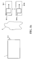
- the mathematical presentation is done taking into account a transmitter having a single code, a single frequency and a single transmitting antenna, as illustrated in figure 1 b.
- the system also comprises a plurality of mobile terminals.
- Figure 1a shows N mobile terminals, receivers or users 30-1 30-2... 30-N attached to said transmitter 1.
- Each one of said N mobile terminals, receivers or users is equipped with a single or multiple receiving antennas 30-1 1 ... 30-1 Z1 30-2 1 ... 30-2 Z2 ... 30-N 1 ... 30-N ZN .
- each of the N users can have a single or several receiving antennas 30-1 1 ... 30-1 Z1 30-2 1 ... 30-2 Z2 ... 30-N 1 ... 30-N ZN , as illustrated in figure 1a , for the sake of simplicity, the mathematical presentation is done with a single antenna 30-1 1 ... 30-N 1 per user, as illustrated in figure 1 b.
- a multiuser channel 2 is shown, through which information between the transmitter 1 and the N mobile terminals, receivers or users 30-1 30-2... 30-N is exchanged. From now on, the term "users" will be used to refer to the N mobile terminals, receivers or users 30-1 30-2... 30-N.
- the invention focuses on the downlink channel (from transmitter 1 to the N mobile users 30-1 30-2... 30-N) where each of the N users is equipped with a single receiving antenna 30-1 1 30-2 1 ... 30-N 1 and the users are served by the transmitter 1, which is provided with a single transmitting antenna 10-1.
- This embodiment is shown in figure 1 b.
- a heterogeneous scenario of a wireless network where users run any of J different classes of applications, J>1.
- One user can simultaneously run several applications having different respective classes.
- a user is assumed to run a single application during a certain time period.
- This wireless network provides users 30-1, 30-2, ... 30-N with different service applications.
- class 1 represents voice users (the most delay-sensitive application) and has the highest priority
- Class J is the lowest priority best-effort class.
- a channel h(t) is considered between each of the users 30-1 30-2... 30-N and the base station (transmitter 1), where a quasi-static block fading model is assumed, which keeps constant through the coherence time, and changes independently between consecutive time intervals with independent and identically distributed (i.i.d.) complex Gaussian entries, with zero mean and unit variance. Therefore, each user 30-1 30-2... 30-N is assumed to keep fixed during each fading block and allowed to move from block to block, so that for the QoS objective, this model captures the instantaneous channel fluctuations in a better approach than the circular rings model.
- the kind of channel h(t) is out of the scope of the present invention. Any other kind of channel can be considered.
- the base station comprises a scheduling unit, which performs the method of selecting the most appropriate user 30-1 30-2... 30-N and transmits the intended data to that selected user.
- the wireless system operates through a maximum throughput scheduler (also called opportunistic scheduler), to boost the system throughput and thus, to enable very high data rates to the users 30-1 30-2... 30-N.
- a maximum throughput scheduler also called opportunistic scheduler
- the main target is in providing a precise and guaranteed QoS control with a certain outage for all the users 30-1 30-2... 30-N, in terms of different parameters, such as the maximum allowed scheduling delay, the minimum allowed rate, the maximum allowed jitter and the minimum guaranteed throughput.
- the DLC (Data Link Control) queue length is optimized.
- the minimum allowed rate and the maximum allowed scheduling delay stand as QoS realistic constraints for both delay constrained and tolerant applications.
- FIG. 2 shows a diagram of the dynamic Data Link Control (DLC) queue scheme of the invention, for efficiently allocating a downlink channel.
- DLC Dynamic Data Link Control
- Reference sign 21 represents an application layer.
- Service applications are assigned one service class or another one (C1, C2, C3, C4) on the basis of the quality-of-service (QoS) required by those applications.
- QoS quality-of-service
- the application layer packets 21 comprise, apart from the actual useful data, an indicator of the instantaneous quality-of-service (QoS) required by the service applications to which they belong.
- QoS quality-of-service
- Non-limiting examples of these indicators of instantaneous QoS are: a maximum allowed scheduling delay, a minimum allowed rate and a minimum guaranteed throughput.
- the application layer packets 21 to be transmitted to any of those users 30-1, 30-2,... 30-N are ordered within queue 221 belonging to a Data Link Control (DLC) layer 22.
- DLC Data Link Control
- This ordering is based on the class C1, C2, C3, C4 of each packet. In other words, it is based on the instantaneous quality of service demand associated to the service application to which that packet belongs. This is shown in figure 2 , where those packets having Class 1 (C1), such as those for voice applications, are ordered at the beginning of the queue 221. Similarly, those packets having Class 4 (C4), which is the lowest priority best-effort class, are ordered at the end of the queue 221.
- C1 Class 1
- C4 Class 4
- This DLC queue 221 is formed by a group of M packets associated to P users (M, P being natural numbers, M ⁇ P) of that plurality of users 30-1 30-2... 30-N of the network.
- These users of the DLC queue 221 are those to which the application layer packets are addressed.
- This number M of packets or users forming the DLC queue 221 is dynamic. This means that the system is able of adjusting the length or size of this queue 221. This is explained later.
- an opportunistic scheduler 23 located at the transmitter 1, allocates a channel to one of those M users.
- the scheduler 23 selects the user which has best channel conditions.
- the scheduler 23 evaluates the channel conditions of each user from previously measured values of a channel parameter.
- the measuring and evaluation method of the channel conditions and the determination of the best channel conditions are out of the scope of the present invention.
- a non-limiting example of such parameter from which the channel conditions can be evaluated is the signal-to-noise ratio for each user.
- the length or size M of the DLC queue 221 is dynamically changed as a function of the different instantaneous quality-of-service demands of the different service applications which are being used by those selected users. This way, the operating point of the system is adjusted.
- the wireless system uses different modulation levels or schemes, so that variable transmission rates depending on the channel conditions (measured, for example, through the received SNR) are obtained.
- An opportunistic scheduler 23 is applied to select the user with the best channel conditions in order to maximize the system throughput.
- the dynamic queue length mechanism 22 when the maximum allowed scheduling delay (or minimum allowed rate or minimum guaranteed throughput) in the delivery of the most delay-sensitive application is smoothly satisfied, the length of the queue 221 can be increased, so that more users can be placed in the DLC layer queue 221. As a consequence, the opportunistic scheduler 23 can select the user with the best channel conditions (for example, highest SNR value) in a bigger pool of choices, increasing by this way the system throughput performance.
- the instantaneous QoS requirements e.g. the maximum allowed scheduling delay
- the length of the DLC queue 23 is decreased. Therefore, only packets from users within the higher priority classes can be available in the DLC layer queue 221, so that the opportunistic scheduler 23 can only select among these users. Therefore, the QoS delay performance is enhanced.
- the instantaneous QoS of the users is a very important aspect and can be characterized by several metrics or indicators based on the design objectives. So, QoS can be expressed in terms of rate, reflecting the minimum required rate per user, or in terms of scheduling delay, showing the maximum allowed scheduling delay that a user can tolerate.
- This proposal considers all of the aforementioned QoS concepts, where the transmission scheme guarantees a minimum allowed rate per user, which is presented by a minimum SNR restriction (SNR th ) per each user within a given maximum allowed scheduling time delay. In particular, this proposal considers either one requirement (preferably, the maximum allowed scheduling delay), or two requirements (preferably, the maximum allowed scheduling delay plus the minimum allowed rate) or three of them (preferably, the maximum allowed scheduling delay plus the minimum allowed rate plus a minimum guaranteed throughput).
- figure 1 refers to a wireless network, such as a WLAN, WiMax, LTE or USTM-HSDPA, providing different real-time service applications.
- a wireless network such as a WLAN, WiMax, LTE or USTM-HSDPA
- an appropriate transmission scheme is required.
- a predefined probability of outage ⁇ out in the QoS is accepted.
- the dynamic adjustment in the size of the queue 221 shows the trade-off between the users' instantaneous QoS demands and the system throughput, where the best operating point depends on the network operator requirements.
- the length M of the dynamic DLC queue 221 (wherein M is the number of available users at the DLC queue 221) is maximized, subject to some system requirements in terms of the users instantaneous QoS demands.
- a proposed optimization procedure for the system performance can be stated as: max M s . t . 1 Pr ⁇ ob SNR i ⁇ SNR th ⁇ ⁇ rate ⁇ i ⁇ M s . t .
- D max is the maximum allowed scheduling delay
- K i is the obtained scheduling delay value
- ⁇ access is the scheduling delay outage.
- T min is the minimum guaranteed throughput while T i is the obtained throughput and ⁇ out is the total allowed outage (explained later).
- This scheme presents the adjustment of the dynamic DLC queue 221 together with the QoS concepts (minimum allowed rate, maximum allowed scheduling delay and minimum guaranteed throughput), where the operator can choose, among the three QoS demands, the most appropriate one or ones for each scenario.
- the scheduling delay outage is related to the access scheme answering to the question: When will the i-th user be served? Under section A, the user access process to the system is analysed and the expression for its access probability is calculated. If a user does not get access to the channel within its maximum allowed scheduling delay, it is declared as being in delay outage ⁇ access .
- the second outage source comes through the awarded rate and answers to the question: Once the i-th user is selected for transmission, would it receive a data rate below its requirements? Under section B, the rate distribution for the selected user is analysed and the minimum guaranteed rate under a given outage ⁇ rate is obtained.
- V(K) is the probability that a maximum of K time slots are required to select a user "i" from a group of N i.i.d. users.
- this section uses the distribution of the serving rate to characterize the rate outage, under a predefined ⁇ rate .
- the serving SNR value is the maximum SNR over the active users in the system.
- PSR Packet Success Rate
- the opportunistic transmission process comes controlled by two different outage measures, but the total performance has to be defined through a single parameter.
- the maximum scheduling delay is defined as the maximum required time to make the packet to be correctly received at its destination. Notice that this definition encloses the delay resulting from the scheduling process (i.e. the maximum throughput selection) together with the delay caused by the channel transmission (i.e. low data rate), therefore providing a general expression for scheduling delay in opportunistic schemes. Therefore, the maximum number of time slots to select a user under a total outage ⁇ out is equal to the K access slots formulation in (4), thus defining the maximum scheduling delay.
- a heterogeneous scenario is set up where users with four types of applications (C1, C2, C3, C4) coexist in the system.
- a total of N 20 users (30-1, 30-2,..., 30-20) are available in the scenario with 5 users for each service traffic class C1, C2, C3, C4.
- the length of the packets for classes C1, C2, C3 and C4 are 100, 512, 1024 and 2312 bytes, respectively.
- Class 1 has the highest priority, while class 4 is the lowest priority class.
- a saturated system is considered, where all users 30-1, 30-2,..., 30-20 have at least one packet ready for transmission.
- a total system bandwidth of 20 MHz and a slot service time of 1 ms is assumed in the simulations.
- a user When a user is selected for transmission, it is awarded all the resources of the system.
- An Indoor complex i.i.d. Gaussian channel with ⁇ CN (0, 1) entries is considered.
- the opportunistic scheduler 23 is employed to select the user with the best received SNR.
- a time scale of 10 6 channel visualizations is employed to display the channel continuous variations.
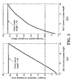
- FIG 3a the percentage of the outage in the maximum allowed scheduling delay satisfaction for Class 1 (C1) users (Y-axis) versus the length of the DLC queue 221 (X-axis) is presented.
- figure 3b shows that, in order to increase the system aggregate throughput (not the guaranteed throughput in expression (10), but the average aggregate throughput in the system) a longer length of the DLC queue 221 is required, so that more users are accepted in the system. This means that class 1 users have lower chances to get access to the channel, which has a direct impact on the time delivery of their packets. As a consequence, the maximum allowed scheduling delay restriction is violated with higher probability and the outage in the delay requirements increases with the length of the queue.
- the dotted line shows an example of what the system can provide in terms of QoS, so that if the class 1 application requires for 20 ms maximum allowed scheduling delay and it can allow for 10% outage, the example shows that 9 users (5 users from class 1 (C1) and 4 users from class 2 (C2)) can be accepted in the dynamic queue, and these 9 users enable the system to offer an average throughput of 2.4Mbps.
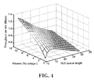
- Figure 4 depicts the system minimum guaranteed throughput to each user for a scenario having a demanded minimum rate of 15 Mbps with variable DLC queue length, as well as a variable allowed outage ⁇ out . It can be seen that there is an optimum DLC queue length M, where the guaranteed throughput has a maximum value for each considered outage. Therefore, the system can be optimized on the basis of its demands and restrictions, to all or to specific classes of users.
- the present invention presents a method of efficiently allocating a downlink wireless channel by dynamically adjusting the length of the Data Link Control (DLC) queue.
- DLC Data Link Control
- the users 30-1 30-2..., 30-N with one or more packets in the queue the user with the best channel conditions is selected 23 for transmission. Therefore, the length of the queue defines the maximum achievable throughput of the system.
- the instantaneous QoS requirements of delay sensitive applications are guaranteed with short DLC queue lengths (dynamically adjusted). A trade-off appears between the system aggregate throughput and the users QoS demands.
- a maximum length M is allowed in order to obtain the highest aggregate system throughput, but restricted to the satisfaction of the users QoS.
- QoS measures and their formulations are presented, so that a wireless operator can choose among them for the most suitable ones for each scenario characteristics and users QoS demands.
Landscapes
- Engineering & Computer Science (AREA)
- Quality & Reliability (AREA)
- Computer Networks & Wireless Communication (AREA)
- Signal Processing (AREA)
- Mobile Radio Communication Systems (AREA)
Claims (12)
- Verfahren zur effizienten Zuweisung eines Downlink-Kanals von einem Sender (1) an einen User, der unter mehreren Usern (30-1, 30-2, ... 30-N) in einem Drahtlosnetzwerk ausgewählt ist, das verschiedene Service-Anwendungen für die User (30-1, 30-2, ... 30-N) bereitstellt, wobei das Verfahren die folgenden Schritte aufweist:- an einer DLC-Warteschlange (221) des Senders (1), Einordnen (221) einer Vielzahl von M Anwendungsschichtpaketen, die an die mehreren User (30-1, 30-2, ... 30-N) übertragen werden sollen, wobei die Einordnung auf der jedem Anwendungsschichtpaket zugeordneten Dienstgütenanforderung basiert, wobei die Dienstgütenanforderungen ihrerseits jeweiligen Anwendungsklassen (C1, C2, C3, C4) zugeordnet sind, wobei die DLC-Warteschlange (221) die Länge M aufweist, wobei M eine natürliche Zahl ist, wobei die M Pakete P Usern der mehreren User (30-1, 30-2, ... 30-N) entsprechen, wobei P≤M, wobei jeder der mehreren User (30-1, 30-2, ... 30-N) zur gleichzeitigen Ausführung mehrerer Anwendungen unterschiedlicher Klassen (C1, C2, C3, C4) konfiguriert ist;gekennzeichnet durch die folgenden Schritte:- dynamisches Ändern der Länge M der DLC-Warteschlange (221) in Abhängigkeit von den verschiedenen momentanen Werten der Dienstgütenanforderungen der verschiedenen Service-Anwendungen, auf welche sich die Anwendungsschichtpakete beziehen, wodurch der Betriebspunkt des Netzwerks eingestellt wird; und- an einem Scheduler (23) des Senders (1), Zuweisen eines Kanals an den User mit den besten Kanalkonditionen der Gruppe von P Usern.
- Verfahren nach Anspruch 1, bei welchem die Dienstgütenanforderungen von mindestens einem der folgenden Faktoren abhängig sind: einer maximalen zulässigen Scheduling-Verzögerung, einer minimalen zulässigen Rate und einem minimalen garantierten Durchsatz.
- Verfahren nach Anspruch 2, bei welchem die Dienstgütenanforderungen unter Berücksichtigung eines vordefinierten Ausfallwerts berechnet werden.
- Verfahren nach Anspruch 2 oder 3, bei welchem die Dienstgütenanforderungen eine Funktion der maximalen zulässigen Scheduling-Verzögerung sind.
- Verfahren nach Anspruch 2 oder 3, bei welchem die Dienstgütenanforderungen eine Funktion der maximalen zulässigen Scheduling-Verzögerung und der minimalen zulässigen Rate sind.
- Verfahren nach Anspruch 2 oder 3, bei welchem die Dienstgütenanforderungen eine Funktion der maximalen zulässigen Scheduling-Verzögerung, der minimalen zulässigen Rate und des minimalen garantierten Durchsatzes sind.
- Verfahren nach Anspruch 6, bei welchem der Wert von M aus dem folgenden Ausdruck berechnet wird:

wobei SNRth einen minimalen erforderlichen SNR-Wert angibt, SNR, der einem User i zur Verfügung gestellte momentane SNR-Wert ist, ξrate ein zulässiger Ratenausfall ist, Dmax eine maximale zulässige Scheduling-Verzögerung angibt, Ki den erhaltenen Scheduling-Verzögerungswert bezeichnet, ξaccess einen Scheduling-Verzögerungsausfall bezeichnet, Tmin ein minimaler garantierter Durchsatz ist, ξout den gesamten zulässigen Ausfall bezeichnet, und die minimale zulässige Rate durch eine Rate/SNR-Beziehung in direkter Beziehung zu SNRth steht. - Verfahren nach einem der vorhergehenden Ansprüche, bei welchem die besten Kanalbedingungen nach einem gemessenen Wert des Signal-Rauschverhältnisses für jeden Benutzer bewertet werden.
- Sender (1) mit Einrichtungen, die zur Durchführung der Schritte des Verfahrens nach einem der Ansprüche 1 bis 8 geeignet sind.
- Basisstation mit mindestens einem Sender (1) nach Anspruch 9.
- Drahtloskommunikationsnetzwerk mit mindestens einer Basisstation nach Anspruch 10.
- Computerprogramm mit Computerprogrammcodeeinrichtungen, die zur Durchführung der Schritte des Verfahrens nach einem der Ansprüche 1 bis 8 geeignet sind, wenn das Programm auf einem Computer, einem Digitalsignalprozessor, einer feldprogrammierbaren Gatteranordnung, einer anwendungsspezifischen integrierten Schaltung, einem MikroProzessor, einem Mikro-Controller oder einer anderen Form von programmierbarer Hardware ausgeführt wird.
Applications Claiming Priority (2)
| Application Number | Priority Date | Filing Date | Title |
|---|---|---|---|
| ES200801308A ES2336748B1 (es) | 2008-05-06 | 2008-05-06 | Procedimiento de asignacion eficiente de canal en sistemas inalambricos. |
| PCT/EP2008/056760 WO2009135534A1 (en) | 2008-05-06 | 2008-06-02 | Method of efficient channel allocation in wireless systems |
Publications (2)
| Publication Number | Publication Date |
|---|---|
| EP2272297A1 EP2272297A1 (de) | 2011-01-12 |
| EP2272297B1 true EP2272297B1 (de) | 2011-12-21 |
Family
ID=40322300
Family Applications (1)
| Application Number | Title | Priority Date | Filing Date |
|---|---|---|---|
| EP08760347A Not-in-force EP2272297B1 (de) | 2008-05-06 | 2008-06-02 | Verfahren für effiziente kanalzuweisung in drahtlosen systemen |
Country Status (5)
| Country | Link |
|---|---|
| US (1) | US8441932B2 (de) |
| EP (1) | EP2272297B1 (de) |
| AT (1) | ATE538619T1 (de) |
| ES (2) | ES2336748B1 (de) |
| WO (1) | WO2009135534A1 (de) |
Families Citing this family (11)
| Publication number | Priority date | Publication date | Assignee | Title |
|---|---|---|---|---|
| US8509129B2 (en) * | 2008-06-04 | 2013-08-13 | General Electric Company | System and method for adjusting media access control parameters in a wireless network |
| US8923873B2 (en) | 2011-11-14 | 2014-12-30 | T-Mobile Usa, Inc. | Device triggered channel selection |
| KR101292309B1 (ko) * | 2011-12-27 | 2013-07-31 | 숭실대학교산학협력단 | 반도체칩 및 메모리 제어방법, 그리고 그 방법을 컴퓨터에서 실행시키기 위한 프로그램을 기록한 기록매체 |
| US9385931B1 (en) * | 2012-03-08 | 2016-07-05 | Sprint Spectrum L.P. | Determining a reordering timer |
| US20130336204A1 (en) * | 2012-06-13 | 2013-12-19 | Jen-Chieh Huang | Control method for adjusting queuing data volumn of wireless communications device by detecting data transfer speed at physical layer and related control module and machine-readable medium thereof |
| US9173229B2 (en) * | 2012-11-26 | 2015-10-27 | Apple Inc. | QoS based buffering while TTI bundling is enabled |
| CN105376723B (zh) * | 2014-08-21 | 2019-06-14 | 中兴通讯股份有限公司 | 一种实现无线链路处理的方法、基站及终端 |
| EP3721669B1 (de) * | 2017-12-05 | 2023-03-29 | Telefonaktiebolaget LM Ericsson (publ) | Downlink-planung von endgerätevorrichtungen |
| CN109905864B (zh) * | 2019-02-28 | 2020-11-03 | 华北电力大学 | 一种面向电力物联网的跨层资源分配方案 |
| US12235777B2 (en) * | 2022-07-08 | 2025-02-25 | Dell Products, L.P. | Managing peripheral device connectivity based on context |
| CN119151264B (zh) * | 2024-11-19 | 2025-03-14 | 南京邮电大学 | 业务需求驱动下主动配电网路由调度和动态选择方法及系统 |
Family Cites Families (14)
| Publication number | Priority date | Publication date | Assignee | Title |
|---|---|---|---|---|
| US6459696B1 (en) * | 1998-06-22 | 2002-10-01 | Nortel Networks Limited | Method and system for avoiding data loss in communications systems |
| US6449255B1 (en) * | 1999-04-26 | 2002-09-10 | Cisco Technology, Inc. | Method and apparatus for managing packets using a real-time feedback signal |
| US6590890B1 (en) | 2000-03-03 | 2003-07-08 | Lucent Technologies Inc. | Method of packet scheduling, with improved delay performance, for wireless networks |
| AU2001259075A1 (en) * | 2000-04-17 | 2001-10-30 | Circadence Corporation | System and method for web serving |
| EP1239637B1 (de) * | 2001-03-09 | 2006-07-12 | Vitesse Semiconductor Corporation | Zeitabhängige Planung für Datenpakete und Verfahren zur Sortierung |
| US6961545B2 (en) * | 2001-04-09 | 2005-11-01 | Atheros Communications, Inc. | Method and system for providing antenna diversity |
| US7746779B2 (en) | 2002-06-03 | 2010-06-29 | Alcatel-Lucent Usa Inc. | Method and apparatus for scheduling users to allocate data transmissions in communications systems |
| GB0302215D0 (en) | 2003-01-30 | 2003-03-05 | Univ Surrey | Method and system for determining optimum resourse allocation in a network |
| US7535839B2 (en) * | 2005-06-30 | 2009-05-19 | Alcatel-Lucent Usa Inc. | Method and apparatus for quality-of-service based admission control using prediction of scheduling gain |
| US20070002750A1 (en) * | 2005-07-01 | 2007-01-04 | Nec Laboratories America, Inc. | Generic Real Time Scheduler for Wireless Packet Data Systems |
| US7480488B2 (en) * | 2005-08-02 | 2009-01-20 | Texas Instruments Incorporated | Providing optimal uplink data rates to mobile stations when mobile networks send parameters controlling the data rates |
| US7804910B2 (en) * | 2006-08-08 | 2010-09-28 | Adaptix, Inc. | Systems and methods for wireless communication system channel allocation using international delay distortion |
| US7715316B2 (en) * | 2007-05-11 | 2010-05-11 | Verizon Services Organization Inc. | Method and apparatus for improving performance in a network using a virtual queue and a switched poisson process traffic model |
| EP2223478B1 (de) * | 2007-12-21 | 2012-11-21 | Telecom Italia S.p.A. | Scheduling-verfahren und system zur kommunikation |
-
2008
- 2008-05-06 ES ES200801308A patent/ES2336748B1/es not_active Expired - Fee Related
- 2008-06-02 EP EP08760347A patent/EP2272297B1/de not_active Not-in-force
- 2008-06-02 US US12/918,495 patent/US8441932B2/en not_active Expired - Fee Related
- 2008-06-02 AT AT08760347T patent/ATE538619T1/de active
- 2008-06-02 ES ES08760347T patent/ES2377035T3/es active Active
- 2008-06-02 WO PCT/EP2008/056760 patent/WO2009135534A1/en not_active Ceased
Also Published As
| Publication number | Publication date |
|---|---|
| ES2336748B1 (es) | 2011-02-10 |
| ATE538619T1 (de) | 2012-01-15 |
| ES2336748A1 (es) | 2010-04-15 |
| WO2009135534A1 (en) | 2009-11-12 |
| ES2377035T3 (es) | 2012-03-21 |
| US20100329119A1 (en) | 2010-12-30 |
| US8441932B2 (en) | 2013-05-14 |
| EP2272297A1 (de) | 2011-01-12 |
Similar Documents
| Publication | Publication Date | Title |
|---|---|---|
| US8441932B2 (en) | Method of efficient channel allocation in wireless systems | |
| JP4675193B2 (ja) | 上りパケットスケジューラ | |
| EP2068579B1 (de) | Drahtloses kommunikationssystem | |
| US20080132173A1 (en) | Channel estimation apparatus and channel estimation method | |
| US8238299B2 (en) | Method and apparatus for scheduling in cellular system using cable relay station | |
| US20080137537A1 (en) | Method for optimal packet scheduling for wireless and mobile communications networks | |
| US9072097B2 (en) | Method for selecting allocable wireless resources, device for selecting allocable wireless resources, and communication device | |
| Elsayed et al. | Reinforcement learning-based joint power and resource allocation for URLLC in 5G | |
| US20070019599A1 (en) | Apparatus and method for scheduling transmission of data packets in a multichannel wireless communication system | |
| KR20040003052A (ko) | 상대적 스루풋 산포도에 기초하여 이동 단말기로의 데이타패킷 송신을 스케쥴링하는 다중 임계 스케쥴러 | |
| WO2013038239A1 (en) | Methods and apparatus for radio resource allocation | |
| WO2008035840A2 (en) | Apparatus and method for fairly allocating resources in band amc mode of wideband wireless access system | |
| CN100469187C (zh) | 一种多天线系统中基于满意度的多用户调度方法 | |
| Zorba et al. | Cross layer QoS guarantees in multiuser WLAN systems | |
| KR100948797B1 (ko) | 이동통신 시스템에서 사용자 스케줄링 장치 및 방법 | |
| US8737287B2 (en) | Scheduling method and apparatus in a relay communication system | |
| Karmakar et al. | S2-GI: Intelligent selection of guard interval in high throughput WLANs | |
| WO2007039513A1 (en) | A method and apparatus for allocation of radio resources | |
| US11191082B2 (en) | Systems and methods for rate selection and resource unit allocation within a wireless local area network (WLAN) | |
| US20260113658A1 (en) | Dynamic bsr tables for uplink buffer size estimation | |
| KR100523996B1 (ko) | 이동통신 시스템의 패킷 스케줄링 시스템 및 방법 | |
| US20060002364A1 (en) | Scheduling data transmission in a wireless communications network | |
| CN100550819C (zh) | 用于基于一个相对的吞吐量分布范围将数据分组传输至移动终端的多门限调度器 | |
| Zorba et al. | A QoS-based dynamic queue length scheduling algorithm in multiantenna heterogeneous systems | |
| CN101346948A (zh) | 依赖于多小区负载的调度 |
Legal Events
| Date | Code | Title | Description |
|---|---|---|---|
| PUAI | Public reference made under article 153(3) epc to a published international application that has entered the european phase |
Free format text: ORIGINAL CODE: 0009012 |
|
| 17P | Request for examination filed |
Effective date: 20100729 |
|
| AK | Designated contracting states |
Kind code of ref document: A1 Designated state(s): AT BE BG CH CY CZ DE DK EE ES FI FR GB GR HR HU IE IS IT LI LT LU LV MC MT NL NO PL PT RO SE SI SK TR |
|
| AX | Request for extension of the european patent |
Extension state: AL BA MK RS |
|
| DAX | Request for extension of the european patent (deleted) | ||
| REG | Reference to a national code |
Ref country code: DE Ref legal event code: R079 Ref document number: 602008012192 Country of ref document: DE Free format text: PREVIOUS MAIN CLASS: H04W0072120000 Ipc: H04W0072080000 |
|
| GRAP | Despatch of communication of intention to grant a patent |
Free format text: ORIGINAL CODE: EPIDOSNIGR1 |
|
| RIC1 | Information provided on ipc code assigned before grant |
Ipc: H04W 72/08 20090101AFI20110831BHEP |
|
| GRAS | Grant fee paid |
Free format text: ORIGINAL CODE: EPIDOSNIGR3 |
|
| GRAA | (expected) grant |
Free format text: ORIGINAL CODE: 0009210 |
|
| AK | Designated contracting states |
Kind code of ref document: B1 Designated state(s): AT BE BG CH CY CZ DE DK EE ES FI FR GB GR HR HU IE IS IT LI LT LU LV MC MT NL NO PL PT RO SE SI SK TR |
|
| REG | Reference to a national code |
Ref country code: GB Ref legal event code: FG4D |
|
| REG | Reference to a national code |
Ref country code: CH Ref legal event code: EP |
|
| REG | Reference to a national code |
Ref country code: AT Ref legal event code: REF Ref document number: 538619 Country of ref document: AT Kind code of ref document: T Effective date: 20120115 |
|
| REG | Reference to a national code |
Ref country code: IE Ref legal event code: FG4D |
|
| REG | Reference to a national code |
Ref country code: DE Ref legal event code: R096 Ref document number: 602008012192 Country of ref document: DE Effective date: 20120223 |
|
| REG | Reference to a national code |
Ref country code: ES Ref legal event code: FG2A Ref document number: 2377035 Country of ref document: ES Kind code of ref document: T3 Effective date: 20120321 |
|
| REG | Reference to a national code |
Ref country code: NL Ref legal event code: VDEP Effective date: 20111221 |
|
| PG25 | Lapsed in a contracting state [announced via postgrant information from national office to epo] |
Ref country code: LT Free format text: LAPSE BECAUSE OF FAILURE TO SUBMIT A TRANSLATION OF THE DESCRIPTION OR TO PAY THE FEE WITHIN THE PRESCRIBED TIME-LIMIT Effective date: 20111221 Ref country code: NO Free format text: LAPSE BECAUSE OF FAILURE TO SUBMIT A TRANSLATION OF THE DESCRIPTION OR TO PAY THE FEE WITHIN THE PRESCRIBED TIME-LIMIT Effective date: 20120321 |
|
| LTIE | Lt: invalidation of european patent or patent extension |
Effective date: 20111221 |
|
| PG25 | Lapsed in a contracting state [announced via postgrant information from national office to epo] |
Ref country code: HR Free format text: LAPSE BECAUSE OF FAILURE TO SUBMIT A TRANSLATION OF THE DESCRIPTION OR TO PAY THE FEE WITHIN THE PRESCRIBED TIME-LIMIT Effective date: 20111221 Ref country code: LV Free format text: LAPSE BECAUSE OF FAILURE TO SUBMIT A TRANSLATION OF THE DESCRIPTION OR TO PAY THE FEE WITHIN THE PRESCRIBED TIME-LIMIT Effective date: 20111221 Ref country code: SI Free format text: LAPSE BECAUSE OF FAILURE TO SUBMIT A TRANSLATION OF THE DESCRIPTION OR TO PAY THE FEE WITHIN THE PRESCRIBED TIME-LIMIT Effective date: 20111221 Ref country code: SE Free format text: LAPSE BECAUSE OF FAILURE TO SUBMIT A TRANSLATION OF THE DESCRIPTION OR TO PAY THE FEE WITHIN THE PRESCRIBED TIME-LIMIT Effective date: 20111221 Ref country code: GR Free format text: LAPSE BECAUSE OF FAILURE TO SUBMIT A TRANSLATION OF THE DESCRIPTION OR TO PAY THE FEE WITHIN THE PRESCRIBED TIME-LIMIT Effective date: 20120322 Ref country code: NL Free format text: LAPSE BECAUSE OF FAILURE TO SUBMIT A TRANSLATION OF THE DESCRIPTION OR TO PAY THE FEE WITHIN THE PRESCRIBED TIME-LIMIT Effective date: 20111221 |
|
| PG25 | Lapsed in a contracting state [announced via postgrant information from national office to epo] |
Ref country code: CY Free format text: LAPSE BECAUSE OF FAILURE TO SUBMIT A TRANSLATION OF THE DESCRIPTION OR TO PAY THE FEE WITHIN THE PRESCRIBED TIME-LIMIT Effective date: 20111221 Ref country code: BE Free format text: LAPSE BECAUSE OF FAILURE TO SUBMIT A TRANSLATION OF THE DESCRIPTION OR TO PAY THE FEE WITHIN THE PRESCRIBED TIME-LIMIT Effective date: 20111221 |
|
| PG25 | Lapsed in a contracting state [announced via postgrant information from national office to epo] |
Ref country code: SK Free format text: LAPSE BECAUSE OF FAILURE TO SUBMIT A TRANSLATION OF THE DESCRIPTION OR TO PAY THE FEE WITHIN THE PRESCRIBED TIME-LIMIT Effective date: 20111221 Ref country code: IS Free format text: LAPSE BECAUSE OF FAILURE TO SUBMIT A TRANSLATION OF THE DESCRIPTION OR TO PAY THE FEE WITHIN THE PRESCRIBED TIME-LIMIT Effective date: 20120421 Ref country code: BG Free format text: LAPSE BECAUSE OF FAILURE TO SUBMIT A TRANSLATION OF THE DESCRIPTION OR TO PAY THE FEE WITHIN THE PRESCRIBED TIME-LIMIT Effective date: 20120321 Ref country code: CZ Free format text: LAPSE BECAUSE OF FAILURE TO SUBMIT A TRANSLATION OF THE DESCRIPTION OR TO PAY THE FEE WITHIN THE PRESCRIBED TIME-LIMIT Effective date: 20111221 Ref country code: EE Free format text: LAPSE BECAUSE OF FAILURE TO SUBMIT A TRANSLATION OF THE DESCRIPTION OR TO PAY THE FEE WITHIN THE PRESCRIBED TIME-LIMIT Effective date: 20111221 |
|
| PG25 | Lapsed in a contracting state [announced via postgrant information from national office to epo] |
Ref country code: PT Free format text: LAPSE BECAUSE OF FAILURE TO SUBMIT A TRANSLATION OF THE DESCRIPTION OR TO PAY THE FEE WITHIN THE PRESCRIBED TIME-LIMIT Effective date: 20120423 Ref country code: PL Free format text: LAPSE BECAUSE OF FAILURE TO SUBMIT A TRANSLATION OF THE DESCRIPTION OR TO PAY THE FEE WITHIN THE PRESCRIBED TIME-LIMIT Effective date: 20111221 Ref country code: RO Free format text: LAPSE BECAUSE OF FAILURE TO SUBMIT A TRANSLATION OF THE DESCRIPTION OR TO PAY THE FEE WITHIN THE PRESCRIBED TIME-LIMIT Effective date: 20111221 |
|
| REG | Reference to a national code |
Ref country code: AT Ref legal event code: MK05 Ref document number: 538619 Country of ref document: AT Kind code of ref document: T Effective date: 20111221 |
|
| PLBE | No opposition filed within time limit |
Free format text: ORIGINAL CODE: 0009261 |
|
| STAA | Information on the status of an ep patent application or granted ep patent |
Free format text: STATUS: NO OPPOSITION FILED WITHIN TIME LIMIT |
|
| PG25 | Lapsed in a contracting state [announced via postgrant information from national office to epo] |
Ref country code: DK Free format text: LAPSE BECAUSE OF FAILURE TO SUBMIT A TRANSLATION OF THE DESCRIPTION OR TO PAY THE FEE WITHIN THE PRESCRIBED TIME-LIMIT Effective date: 20111221 |
|
| 26N | No opposition filed |
Effective date: 20120924 |
|
| PG25 | Lapsed in a contracting state [announced via postgrant information from national office to epo] |
Ref country code: IT Free format text: LAPSE BECAUSE OF FAILURE TO SUBMIT A TRANSLATION OF THE DESCRIPTION OR TO PAY THE FEE WITHIN THE PRESCRIBED TIME-LIMIT Effective date: 20111221 |
|
| REG | Reference to a national code |
Ref country code: DE Ref legal event code: R097 Ref document number: 602008012192 Country of ref document: DE Effective date: 20120924 |
|
| PG25 | Lapsed in a contracting state [announced via postgrant information from national office to epo] |
Ref country code: MC Free format text: LAPSE BECAUSE OF NON-PAYMENT OF DUE FEES Effective date: 20120630 Ref country code: AT Free format text: LAPSE BECAUSE OF FAILURE TO SUBMIT A TRANSLATION OF THE DESCRIPTION OR TO PAY THE FEE WITHIN THE PRESCRIBED TIME-LIMIT Effective date: 20111221 |
|
| REG | Reference to a national code |
Ref country code: CH Ref legal event code: PL |
|
| REG | Reference to a national code |
Ref country code: CH Ref legal event code: PL |
|
| REG | Reference to a national code |
Ref country code: IE Ref legal event code: MM4A |
|
| PG25 | Lapsed in a contracting state [announced via postgrant information from national office to epo] |
Ref country code: IE Free format text: LAPSE BECAUSE OF NON-PAYMENT OF DUE FEES Effective date: 20120602 Ref country code: LI Free format text: LAPSE BECAUSE OF NON-PAYMENT OF DUE FEES Effective date: 20120630 Ref country code: CH Free format text: LAPSE BECAUSE OF NON-PAYMENT OF DUE FEES Effective date: 20120630 |
|
| PG25 | Lapsed in a contracting state [announced via postgrant information from national office to epo] |
Ref country code: FI Free format text: LAPSE BECAUSE OF FAILURE TO SUBMIT A TRANSLATION OF THE DESCRIPTION OR TO PAY THE FEE WITHIN THE PRESCRIBED TIME-LIMIT Effective date: 20111221 |
|
| PG25 | Lapsed in a contracting state [announced via postgrant information from national office to epo] |
Ref country code: MT Free format text: LAPSE BECAUSE OF FAILURE TO SUBMIT A TRANSLATION OF THE DESCRIPTION OR TO PAY THE FEE WITHIN THE PRESCRIBED TIME-LIMIT Effective date: 20111221 |
|
| PG25 | Lapsed in a contracting state [announced via postgrant information from national office to epo] |
Ref country code: TR Free format text: LAPSE BECAUSE OF FAILURE TO SUBMIT A TRANSLATION OF THE DESCRIPTION OR TO PAY THE FEE WITHIN THE PRESCRIBED TIME-LIMIT Effective date: 20111221 |
|
| PG25 | Lapsed in a contracting state [announced via postgrant information from national office to epo] |
Ref country code: LU Free format text: LAPSE BECAUSE OF NON-PAYMENT OF DUE FEES Effective date: 20120602 |
|
| PG25 | Lapsed in a contracting state [announced via postgrant information from national office to epo] |
Ref country code: HU Free format text: LAPSE BECAUSE OF FAILURE TO SUBMIT A TRANSLATION OF THE DESCRIPTION OR TO PAY THE FEE WITHIN THE PRESCRIBED TIME-LIMIT Effective date: 20080602 |
|
| REG | Reference to a national code |
Ref country code: FR Ref legal event code: PLFP Year of fee payment: 8 |
|
| PGFP | Annual fee paid to national office [announced via postgrant information from national office to epo] |
Ref country code: GB Payment date: 20150618 Year of fee payment: 8 Ref country code: DE Payment date: 20150609 Year of fee payment: 8 Ref country code: ES Payment date: 20150612 Year of fee payment: 8 |
|
| PGFP | Annual fee paid to national office [announced via postgrant information from national office to epo] |
Ref country code: FR Payment date: 20150617 Year of fee payment: 8 |
|
| REG | Reference to a national code |
Ref country code: DE Ref legal event code: R119 Ref document number: 602008012192 Country of ref document: DE |
|
| GBPC | Gb: european patent ceased through non-payment of renewal fee |
Effective date: 20160602 |
|
| REG | Reference to a national code |
Ref country code: FR Ref legal event code: ST Effective date: 20170228 |
|
| PG25 | Lapsed in a contracting state [announced via postgrant information from national office to epo] |
Ref country code: DE Free format text: LAPSE BECAUSE OF NON-PAYMENT OF DUE FEES Effective date: 20170103 Ref country code: FR Free format text: LAPSE BECAUSE OF NON-PAYMENT OF DUE FEES Effective date: 20160630 |
|
| PG25 | Lapsed in a contracting state [announced via postgrant information from national office to epo] |
Ref country code: GB Free format text: LAPSE BECAUSE OF NON-PAYMENT OF DUE FEES Effective date: 20160602 |
|
| PG25 | Lapsed in a contracting state [announced via postgrant information from national office to epo] |
Ref country code: ES Free format text: LAPSE BECAUSE OF NON-PAYMENT OF DUE FEES Effective date: 20160603 |
|
| REG | Reference to a national code |
Ref country code: ES Ref legal event code: FD2A Effective date: 20181204 |