EP2272180B1 - Method for transmitting and receiving signals in open-loop spatial multiplexing mode - Google Patents
Method for transmitting and receiving signals in open-loop spatial multiplexing mode Download PDFInfo
- Publication number
- EP2272180B1 EP2272180B1 EP09718805.6A EP09718805A EP2272180B1 EP 2272180 B1 EP2272180 B1 EP 2272180B1 EP 09718805 A EP09718805 A EP 09718805A EP 2272180 B1 EP2272180 B1 EP 2272180B1
- Authority
- EP
- European Patent Office
- Prior art keywords
- matrix
- precoding
- cdd
- index
- open
- Prior art date
- Legal status (The legal status is an assumption and is not a legal conclusion. Google has not performed a legal analysis and makes no representation as to the accuracy of the status listed.)
- Active
Links
- 238000000034 method Methods 0.000 title claims description 51
- 239000011159 matrix material Substances 0.000 claims description 130
- 230000005540 biological transmission Effects 0.000 claims description 40
- 125000004122 cyclic group Chemical group 0.000 claims description 13
- 230000000875 corresponding effect Effects 0.000 description 18
- 230000010363 phase shift Effects 0.000 description 15
- 238000004891 communication Methods 0.000 description 8
- 238000000819 phase cycle Methods 0.000 description 5
- 238000004088 simulation Methods 0.000 description 4
- 230000007774 longterm Effects 0.000 description 2
- 238000013507 mapping Methods 0.000 description 2
- 238000012935 Averaging Methods 0.000 description 1
- 241000760358 Enodes Species 0.000 description 1
- 230000006978 adaptation Effects 0.000 description 1
- 230000002596 correlated effect Effects 0.000 description 1
- 230000003247 decreasing effect Effects 0.000 description 1
- 230000001934 delay Effects 0.000 description 1
- 230000003111 delayed effect Effects 0.000 description 1
- 238000010586 diagram Methods 0.000 description 1
- 230000000694 effects Effects 0.000 description 1
- 238000005562 fading Methods 0.000 description 1
- 238000010295 mobile communication Methods 0.000 description 1
- 238000013139 quantization Methods 0.000 description 1
- 238000013468 resource allocation Methods 0.000 description 1
- 230000011664 signaling Effects 0.000 description 1
- 238000006467 substitution reaction Methods 0.000 description 1
Images


Classifications
-
- H—ELECTRICITY
- H04—ELECTRIC COMMUNICATION TECHNIQUE
- H04B—TRANSMISSION
- H04B7/00—Radio transmission systems, i.e. using radiation field
- H04B7/02—Diversity systems; Multi-antenna system, i.e. transmission or reception using multiple antennas
- H04B7/04—Diversity systems; Multi-antenna system, i.e. transmission or reception using multiple antennas using two or more spaced independent antennas
- H04B7/0413—MIMO systems
- H04B7/0456—Selection of precoding matrices or codebooks, e.g. using matrices antenna weighting
- H04B7/0486—Selection of precoding matrices or codebooks, e.g. using matrices antenna weighting taking channel rank into account
-
- H—ELECTRICITY
- H04—ELECTRIC COMMUNICATION TECHNIQUE
- H04B—TRANSMISSION
- H04B7/00—Radio transmission systems, i.e. using radiation field
- H04B7/02—Diversity systems; Multi-antenna system, i.e. transmission or reception using multiple antennas
- H04B7/04—Diversity systems; Multi-antenna system, i.e. transmission or reception using multiple antennas using two or more spaced independent antennas
- H04B7/06—Diversity systems; Multi-antenna system, i.e. transmission or reception using multiple antennas using two or more spaced independent antennas at the transmitting station
- H04B7/0613—Diversity systems; Multi-antenna system, i.e. transmission or reception using multiple antennas using two or more spaced independent antennas at the transmitting station using simultaneous transmission
- H04B7/0667—Diversity systems; Multi-antenna system, i.e. transmission or reception using multiple antennas using two or more spaced independent antennas at the transmitting station using simultaneous transmission of delayed versions of same signal
- H04B7/0671—Diversity systems; Multi-antenna system, i.e. transmission or reception using multiple antennas using two or more spaced independent antennas at the transmitting station using simultaneous transmission of delayed versions of same signal using different delays between antennas
-
- H—ELECTRICITY
- H04—ELECTRIC COMMUNICATION TECHNIQUE
- H04B—TRANSMISSION
- H04B7/00—Radio transmission systems, i.e. using radiation field
- H04B7/02—Diversity systems; Multi-antenna system, i.e. transmission or reception using multiple antennas
- H04B7/04—Diversity systems; Multi-antenna system, i.e. transmission or reception using multiple antennas using two or more spaced independent antennas
- H04B7/06—Diversity systems; Multi-antenna system, i.e. transmission or reception using multiple antennas using two or more spaced independent antennas at the transmitting station
- H04B7/0613—Diversity systems; Multi-antenna system, i.e. transmission or reception using multiple antennas using two or more spaced independent antennas at the transmitting station using simultaneous transmission
- H04B7/0682—Diversity systems; Multi-antenna system, i.e. transmission or reception using multiple antennas using two or more spaced independent antennas at the transmitting station using simultaneous transmission using phase diversity (e.g. phase sweeping)
-
- H—ELECTRICITY
- H04—ELECTRIC COMMUNICATION TECHNIQUE
- H04B—TRANSMISSION
- H04B7/00—Radio transmission systems, i.e. using radiation field
- H04B7/02—Diversity systems; Multi-antenna system, i.e. transmission or reception using multiple antennas
- H04B7/04—Diversity systems; Multi-antenna system, i.e. transmission or reception using multiple antennas using two or more spaced independent antennas
- H04B7/06—Diversity systems; Multi-antenna system, i.e. transmission or reception using multiple antennas using two or more spaced independent antennas at the transmitting station
- H04B7/0697—Diversity systems; Multi-antenna system, i.e. transmission or reception using multiple antennas using two or more spaced independent antennas at the transmitting station using spatial multiplexing
-
- H—ELECTRICITY
- H04—ELECTRIC COMMUNICATION TECHNIQUE
- H04B—TRANSMISSION
- H04B7/00—Radio transmission systems, i.e. using radiation field
- H04B7/02—Diversity systems; Multi-antenna system, i.e. transmission or reception using multiple antennas
- H04B7/04—Diversity systems; Multi-antenna system, i.e. transmission or reception using multiple antennas using two or more spaced independent antennas
- H04B7/06—Diversity systems; Multi-antenna system, i.e. transmission or reception using multiple antennas using two or more spaced independent antennas at the transmitting station
- H04B7/0613—Diversity systems; Multi-antenna system, i.e. transmission or reception using multiple antennas using two or more spaced independent antennas at the transmitting station using simultaneous transmission
- H04B7/0615—Diversity systems; Multi-antenna system, i.e. transmission or reception using multiple antennas using two or more spaced independent antennas at the transmitting station using simultaneous transmission of weighted versions of same signal
- H04B7/0619—Diversity systems; Multi-antenna system, i.e. transmission or reception using multiple antennas using two or more spaced independent antennas at the transmitting station using simultaneous transmission of weighted versions of same signal using feedback from receiving side
- H04B7/0621—Feedback content
- H04B7/0634—Antenna weights or vector/matrix coefficients
-
- H—ELECTRICITY
- H04—ELECTRIC COMMUNICATION TECHNIQUE
- H04B—TRANSMISSION
- H04B7/00—Radio transmission systems, i.e. using radiation field
- H04B7/02—Diversity systems; Multi-antenna system, i.e. transmission or reception using multiple antennas
- H04B7/04—Diversity systems; Multi-antenna system, i.e. transmission or reception using multiple antennas using two or more spaced independent antennas
- H04B7/06—Diversity systems; Multi-antenna system, i.e. transmission or reception using multiple antennas using two or more spaced independent antennas at the transmitting station
- H04B7/0613—Diversity systems; Multi-antenna system, i.e. transmission or reception using multiple antennas using two or more spaced independent antennas at the transmitting station using simultaneous transmission
- H04B7/0615—Diversity systems; Multi-antenna system, i.e. transmission or reception using multiple antennas using two or more spaced independent antennas at the transmitting station using simultaneous transmission of weighted versions of same signal
- H04B7/0619—Diversity systems; Multi-antenna system, i.e. transmission or reception using multiple antennas using two or more spaced independent antennas at the transmitting station using simultaneous transmission of weighted versions of same signal using feedback from receiving side
- H04B7/0636—Feedback format
- H04B7/0639—Using selective indices, e.g. of a codebook, e.g. pre-distortion matrix index [PMI] or for beam selection
-
- H—ELECTRICITY
- H04—ELECTRIC COMMUNICATION TECHNIQUE
- H04L—TRANSMISSION OF DIGITAL INFORMATION, e.g. TELEGRAPHIC COMMUNICATION
- H04L25/00—Baseband systems
- H04L25/02—Details ; arrangements for supplying electrical power along data transmission lines
- H04L25/03—Shaping networks in transmitter or receiver, e.g. adaptive shaping networks
- H04L25/03891—Spatial equalizers
- H04L25/03898—Spatial equalizers codebook-based design
-
- H—ELECTRICITY
- H04—ELECTRIC COMMUNICATION TECHNIQUE
- H04L—TRANSMISSION OF DIGITAL INFORMATION, e.g. TELEGRAPHIC COMMUNICATION
- H04L27/00—Modulated-carrier systems
- H04L27/26—Systems using multi-frequency codes
- H04L27/2601—Multicarrier modulation systems
- H04L27/2626—Arrangements specific to the transmitter only
Definitions
- the present invention relates to a multiple-input multiple-output (MIMO) mobile communication system, and more particularly, to a method for efficiently transmitting and receiving signals in an open-loop spatial multiplexing mode.
- MIMO multiple-input multiple-output
- the multiple transmit and receive antenna technique obtains a diversity gain by equipping a transmitter and a receiver with a plurality of antennas to additionally ensure a spatial region for utilizing resources, or increases transmission capacity by transmitting data in parallel through the respective antennas.
- a MIMO system using an orthogonal frequency division multiplexing (OFDM) among the multiple transmit and receive antenna techniques will now be described.
- OFDM orthogonal frequency division multiplexing
- FIG. 1 illustrates a general structure of a multiple transmit and receive antenna system using OFDM.
- a channel encoder 101 adds redundancy bits to transmission data bits to reduce an influence of a channel or noise, and a mapper 103 converts data bit information into data symbol information.
- a serial-to-parallel converter 105 parallelizes the data symbol information to carry data symbols on a plurality of subcarriers.
- a multiple antenna encoder 107 converts the parallelized data symbols into time-space signals.
- a multiple antenna decoder 109 In a receiving side, a multiple antenna decoder 109, a parallel-to-serial converter 111, a demapper 113, and a channel decoder 115 respectively perform the reverse functions of the functions performed in the multiple antenna encoder 107, the serial-to-parallel converter 105, the mapper 103, and the channel encoder 101 of the transmitting side.
- the multiple antenna OFDM system requires various techniques to improve the reliability of data transmission.
- a space-time coding (STC) scheme and a cyclic delay diversity (CDD) scheme are used to raise a spatial diversity gain.
- a beam forming scheme and a precoding scheme are used to increase a signal-to-noise ratio (SNR).
- the STC and CDD schemes are mainly used to improve transmission reliability of an open-loop system which can not use feedback information in a transmitting side.
- the beam forming and precoding schemes are used to maximize the SNR through corresponding feedback information in a closed-loop system which is capable of using feedback information in the transmitting side.
- the CDD scheme causes all antennas to transmit signals with different delays or different sizes in transmitting OFDM signals in a system having multiple transmit antennas, so that a receiving side obtains a frequency diversity gain.
- FIG. 2 illustrates a structure of a transmitting side of a multiple antenna system using a CDD scheme.
- a cyclic prefix for preventing interference between channels is added and then transmitted to a receiving side.
- a data sequence transmitted to the first antenna is transmitted to the receiving side without delay, and data sequences transmitted to the next antennas are cyclically delayed by a predetermined sample compared with the preceding antennas.
- the cyclic delay may be expressed as a multiplication of phase sequences.
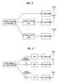
- FIG. 3 illustrates a method for performing the CDD scheme shown in FIG. 2 in a frequency domain.
- phase sequences in a frequency domain are multiplied by phase sequences (phase sequence 1 to phase sequence M) which are differently set according to antennas, and thereafter, inverse fast Fourier transform (IFFT) is performed to transmit the data sequences to a receiving side.
- IFFT inverse fast Fourier transform
- the phase-shift diversity scheme may convert a flat fading channel into a frequency selective channel, and obtain a frequency diversity gain through a channel code or a multi-user diversity gain through frequency selective scheduling.
- the precoding scheme includes a codebook based precoding method used when feedback information is finite in a closed-loop system and a method for performing feedback upon quantization of channel information.
- Codebook based precoding refers to obtaining an SNR gain by feeding back an index of a precoding matrix, which is previously known by transmitting and receiving sides, to the transmitting side.
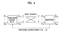
- FIG. 4 illustrates a structure of transmitting and receiving sides of a multiple antenna system using codebook based precoding.
- the transmitting side and receiving side respectively include finite precoding matrixes P 1 to P L .
- the receiving side feeds back an optimal precoding matrix index I to the transmitting side using channel information.
- the transmitting side may apply a precoding matrix corresponding to the fed back index to transmission data X 1 to X Mt .
- phase-shift diversity scheme or the CDD scheme may have different requirements in an open-loop type and a closed-loop type depending on whether the feedback information is demanded. That is, it may be desirable that different precoding matrixes be used in an open-loop CDD scheme and a closed-loop CDD scheme.
- the 3GPP draft R1-070655 titled "CDD Based Precoding for DL MIMO" by QUALCOMM Europe focuses on an operational advantage of the CDD precoding that minimizes the explicit mode switching. Further, a few related issues such as common pilot transmission, desirable delay values and others are discussed.
- the 3GPP draft R1-080579 proposes some further details on the definition of the large delay CDD MIMO scheme defined in TS36.211.
- An object of the present invention devised to solve the problem lies in providing a method for selecting a precoding matrix which can simplify achievement while obtaining a sufficient frequency diversity gain under various channel environments according to transmission modes.
- Another object of the present invention devised to solve the problem lies in providing a method for efficiently transmitting and receiving signals between transmitting and receiving sides according to CDD schemes using the selected precoding matrix.
- a method for precoding at a transmitter when a transmission rank is greater than 1 comprises precoding signals by a matrix for large delay cyclic delay diversity, CDD, based precoding, in an open-loop spatial multiplexing, SM, transmission mode.
- the matrix can be generated in a form of WDU in which a first matrix, W, a second matrix, D, being a large delay CDD diagonal matrix, and a third matrix, U, being a unitary matrix are sequentially multiplied.
- the first matrix is fixedly used as an identity matrix.
- the number of transmit antennas is 4, the first matrix is cyclically changed within 4 predetermined matrixes.
- a method for a user equipment to receive signals in an open-loop spatial multiplexing transmission mode includes: receiving information about a rank indicator (RI) and the number of antennas from a base station; and if the number of transmit antennas is 2, estimating that the base station transmits signals through precoding by a matrix (WDU) in which a first matrix (W) corresponding to an identity matrix (I), a second matrix (D) corresponding to a diagonal matrix, and a third matrix (U) corresponding to a unitary matrix are sequentially multiplied; and receiving signals according to the estimation result.
- the rank indicator indicates a number greater than 1
- the method may further include estimating that the base station transmits signals according to a cyclic delay diversity (CDD) scheme.
- CDD cyclic delay diversity
- a method for a base station to transmit signals in an open-loop spatial multiplexing transmission mode includes: if a transmission rank is greater than 1, transmitting signals according to a cyclic delay diversity (CDD) scheme, wherein the transmitting of signals includes, if the number of transmit antennas is 2, performing precoding of transmission signals by a matrix (WDU) in which a first matrix (W) corresponding to an identity matrix (I), a second matrix (D) corresponding to a diagonal matrix, and a third matrix (U) corresponding to a unitary matrix are sequentially multiplied; and mapping the precoded signals to resource elements and transmitting the mapped signals.
- CDD cyclic delay diversity
- the second matrix (D) may be a 2 ⁇ 2 matrix when the number of transmit antennas is 2 and a rank designated by the rank indicator is 2.
- the base station in the open-loop spatial multiplexing transmission mode may fixedly use the first matrix as 1 2 1 0 0 1 , and the user equipment may not feed back a precoding matrix index to the base station.
- Futhermore a method for a base station to transmit signals in an open-loop spatial multiplexing transmission mode is disclosed.
- the method includes: if the number of transmit antennas is 2 and a transmission rank is 2, performing precoding of transmission signals according to a cyclic delay diversity (CDD) scheme by a matrix (DU) in which a first matrix (D) corresponding to a diagonal matrix and a second matrix (U) corresponding to a unitary matrix are sequentially multiplied; and mapping the precoded signals to resource elements and transmitting the mapped signals.
- CDD cyclic delay diversity
- a sufficient diversity gain can be simply achieved for each transmission mode.
- a method for selecting a precoding matrix which can obtain a sufficient frequency diversity gain in various channel environments according to transmission modes and can be easily achieved, and for efficiently transmitting and receiving signals using the selected precoding matrix.
- a downlink of the 3GPP LTE system according to transmission modes will be described in detail and a method for transmitting and receiving signals according to a CDD scheme by efficiently constructing the precoding matrix in an open-loop spatial multiplexing mode will be described.
- the downlink of the 3GPP LTE system is illustrative only and the present invention may be applied to other wireless communication environments.
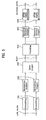
- FIG. 5 is a conceptual view schematically illustrating a transmission process of a downlink physical channel in a 3GPP LTE system.
- Codewords generated through channel coding are scrambled in scramblers 501 through which scrambled bit blocks are generated.
- the bit blocks are generated by modulation mappers 502 as modulation symbols modulated to quadrature phase-shift keying (QPSK), 16 quadrature amplitude modulation (16 QAM), or 64 QAM.
- the modulation symbols are mapped to one or more layers by a layer mapper 503.
- up to two codewords can be simultaneously transmitted and the two codewords may be mapped to four or less layers according to a prescribed reference.
- the layer-mapped symbols are precoded by a precoder 504.
- the precoding scheme includes: (1) precoding for spatial multiplexing (SM); and (2) precoding for spatial transmission diversity.
- the precoding for SM includes: (a) precoding for SM without the application of CDD; and (b) precoding for large delay CDD.
- a base station transmits signals according to a CDD based precoding scheme.
- the base station may transmit signals through precoding based on a fixed, specific precoding matrix.
- the base station may transmit signals by cyclically applying different precoding schemes to respective resource elements.
- the transmission symbols which have been precoded are mapped to proper resource elements by resource element mappers 505 and transmitted through transmission antennas via OFDM signal generators 506.
- the precoding for SM in the above-described precoding schemes utilizes methods for reducing signaling overhead using a specific precoding matrix within a predetermined codebook between transmitting and receiving sides.
- the precoding for large delay CDD will be described below in detail.
- the precoding for large delay CDD may be referred to as a 'CDD based precoding', 'CDD precoding', or 'phase-shift based precoding' unless such use causes confusion.
- the phase-shift based precoding serves to transmit all streams to be transmitted through all antennas after being multiplied by sequences of different phases.
- a frequency selective channel is generated in terms of a receiver and the size of a channel is increased or decreased according to a frequency region.
- a phase-shift based precoding matrix P can be expressed in the following manner.
- P N t ⁇ R k w 1 , 1 k w 1 , 2 k ⁇ w 1 , R k w 2 , 1 k w 2 , 2 k ⁇ w 2 , R k ⁇ ⁇ ⁇ ⁇ w N t , 1 k w N t , 2 k ⁇ w N t , R k
- k indicates a resource index, for example, a subcarrier index, or a virtual time-frequency resource or a specific frequency band index
- N t indicates the number of transmit antennas
- R indicates an SM rate.
- the complex weight value may have different values according to an OFDM symbol multiplied to the antennas and a corresponding subcarrier index.
- the complex weight value may be determined according to at least one of a channel environment and presence/absence of feedback information.
- the precoding matrix P of Equation 1 is desirably designed to reduce the loss in channel capacity of a multiple antenna system.
- Equation 3 log 2 ⁇ det ⁇ I N r + SNR N ⁇ H ⁇ PP H ⁇ H H
- phase-shift based precoding matrix P is based on a unitary matrix.
- Equation 5 The afore-described phase-shift based precoding matrix may be expressed as the following Equation 5 with respect to a system in which the number of antennas is N t (where N t is a natural number equal to or greater than 2) and an SM rate is R (where R is a natural number equal to or greater than 1). Since Equation 5 may be obtained by generalizing a conventional phase-shift diversity scheme, a multiple antenna scheme of Equation 5 will be referred to as generalized phase-shift diversity (GPSD).
- GPSD generalized phase-shift diversity
- GPSD N t ⁇ R k indicates a GPSD matrix for a kth resource index of a MIMO-OFDM signal having N t transmission antennas and an SM rate R
- is a square matrix (that is, N t R) and is used to minimize interference between subcarrier symbols corresponding to respective antennas.
- U Nt ⁇ R is desired to satisfy the condition of a unitary matrix in order to maintain characteristics of the unitary matrix of a diagonal matrix (a first matrix, D) for phase shift.
- ⁇ i - 2 ⁇ ⁇ / N fft ⁇ ⁇ i
- N fft denotes the number of subcarriers of an OFDM signal.
- a precoding matrix obtained by multiplying the first matrix corresponding to the diagonal matrix D by the second matrix corresponding to the unitary matrix U will be referred to as a 'basic structure of CDD based precoding' or a 'DU structure'.
- an expanded CDD based precoding matrix may be constructed by adding a precoding matrix P selected from a codebook predetermined between transmitting and receiving sides to the basic structure of CDD based precoding comprised of a diagonal matrix D and a unitary matrix U.
- This may be expressed as follows.
- GPSD N t ⁇ R k P N t ⁇ R ⁇ e j ⁇ ⁇ 1 ⁇ k 0 ⁇ 0 0 e j ⁇ ⁇ 2 ⁇ k ⁇ 0 ⁇ ⁇ ⁇ ⁇ 0 0 ⁇ e j ⁇ ⁇ R k ⁇ U R ⁇ R
- the extended CDD based precoding matrix includes a precoding matrix P having a size of N t x R added in front of the diagonal matrix compared to the matrix of Equation 5. Therefore, the size of the diagonal matrix is modified to R x R.
- the added precoding matrix P N t ⁇ R may be differently set with respect to a specific frequency band or a specific subcarrier symbol and may be desirably set to use a fixed specific matrix in an open-loop system. A more optimized SNR ratio can be obtained by addition of the precoding matrix P N t ⁇ R .
- the added precoding matrix is selected from a codebook of a 3GPP LTE system and may be denoted as 'W'.
- the expanded CDD based precoding matrix described above will be referred to as a 'PDU structure' or 'WDU structure.
- a codebook which is predetermined between transmitting and receiving sides for a 2-Tx system and a 4-Tx system in a 3GPP LTE system is shown in below.
- Table 1 shows a codebook used in a 2-Tx system and Table 2 shows a codebook used in a 4-Tx system.
- a codebook including N c precoding matrixes may use a codebook subset restriction technique which uses only a part of the codebook according to a base station and a mobile terminal.
- N c precoding matrixes may be restricted to N restrict precoding matrixes.
- the codebook subset restriction technique may be used to reduce multiple cell interference or to reduce complexity. It is assumed that Nrestrict ⁇ N c . For example, if the total number N c of precoding matrixes of a codebook is 6, a codebook P N t ⁇ R of an entire set and a codebook P N t ⁇ R restrict which is determined to use only four precoding matrixes among 6 precoding matrixes can be expressed by the following Equation 8.
- W N t ⁇ R is an equivalent codebook rearranging an index of the codebook P N t ⁇ R restrict .
- Equation 9 may be obtained.
- P N t ⁇ R P N t ⁇ R 0 P N t ⁇ R 1 ⁇ P N t ⁇ R N c - 1 GPSD
- N t ⁇ R k P N t ⁇ R k mod N c ⁇ e j ⁇ ⁇ 1 ⁇ k 0 ⁇ 0 0 e j ⁇ ⁇ 2 ⁇ k ⁇ 0 ⁇ ⁇ 0 0 0 0 e j ⁇ ⁇ R ⁇ k U R ⁇ R
- Equation 8 and Equation 9 indicate methods using precoding matrixes by cyclic repetition within the codebook P N t ⁇ R according to subcarriers or resource indexes.
- ⁇ R ⁇ R k serves to mix data streams.
- ⁇ R ⁇ R k which may be referred to as a data stream substitution matrix, may be selected according to an SM rate R as indicated in Equation 9.
- ⁇ R ⁇ R k may be expressed as a simple form as shown in the following Equation 11.
- Equation 10 may be expressed as follows.
- Equation 12 shows a method using precoding matrixes by cyclic repetition within W N t ⁇ R indicating a codebook in which a precoding matrix is restricted according to subcarriers or resource indexes.
- a precoding matrix W may be fixed to any one for simple achievement.
- a method for selecting a desirable precoding matrix when performing the CDD based precoding using the fixed precoding matrix will be described.
- CDD based precoding method in open-loop spatial multiplexing (SM) mode CDD based precoding method in open-loop spatial multiplexing (SM) mode
- the large delay CDD precoding of an open-loop SM mode may be performed according to the PDU structure or WDU structure as indicated by the above Equation 7.
- the large delay CDD precoding may be expressed as follows. W N t ⁇ R ⁇ i v ⁇ mod N c ⁇ 1 0 0 0 0 e j ⁇ ⁇ 1 ⁇ i 0 0 0 0 ⁇ 0 0 0 e j ⁇ ⁇ R - 1 ⁇ i ⁇ D i U R ⁇ R
- N c indicates the number of precoding matrixes within a codebook subset
- ⁇ indicates the number of successive resource elements using the same precoding matrix
- i is a resource index like k. Therefore, the precoding matrix is modified every resource index i so that N c precoding matrixes may be cyclically used.
- rank 2 is considered from Table 1 as follows.
- rank ⁇ 2 1 2 1 0 0 1 ⁇ , index_ 0 ⁇ 1 2 ⁇ 1 1 1 - 1 ⁇ index_ 1 , 1 2 ⁇ 1 1 j - j ⁇ index_ 2
- index 1 and index 2 perform a function similar to an identity matrix performing column switching when combined with the large delay CDD.
- the open-loop SM serves as a discrete Fourier transform (DFT) matrix performing column switching and can obtain a high SNR gain in a moderate correlation channel.
- DFT discrete Fourier transform
- a method for performing precoding for rank 2 in a 2-Tx open-loop SM transmission mode by a matrix WDU or PDU in which a first matrix W corresponding to an identity matrix of index 0 of Equation 14, a second matrix D corresponding to a diagonal matrix, and a third matrix U corresponding to a unitary matrix are sequentially multiplied, and for transmitting the precoded signals.
- the present inventor performed the following simulation to determine if there was any difference in performance when a matrix of index 0 as the first matrix W is used and when a matrix of index 1 or index 2 as the first matrix W is used.
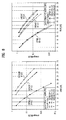
- FIG. 6 is graphs illustrating a comparison of performances when using index 0 and index 1 for rank 2 of a 2-Tx codebook with respect to open-loop SM in an ITU-pedestrian A (PedA) channel.
- PedA ITU-pedestrian A
- FIG. 7 is graphs illustrating a comparison of performances when using index 0 and index 1 for rank 2 of a 2-Tx codebook with respect to open-loop SM in a 6-Ray typical urban (TU) channel.
- FIG. 7 shows a performance comparison similar to FIG. 6 except for a channel mode. As depicted in FIG. 7 , an improved performance gain is provided even in a sufficient frequency diversity channel when using index 0.
- the method for a mobile terminal to receive signals from a base station may be summarized as follows.
- the mobile terminal receives signals in an open-loop SM transmission mode
- receives a rank indicator through downlink control information. If the received rank indicator indicates 1, the mobile terminal estimates that the base station transmits signals according to a transmission diversity scheme. If the received rank indicator indicates a number greater than 1, the mobile terminal estimates that the base station transmits signals according to a CDD scheme.
- a signal receiving method may vary according to the number of transmit antennas. Namely, in case of 4 Tx antennas, the mobile terminal estimates that the base station performs precoding by cyclically applying 4 precoding matrixes among 16 codebooks to P or W of the PDU/WDU structure. In case of 2 Tx antennas, the mobile terminal estimates that the base station performs precoding by applying an identity matrix corresponding to index 0 of Equation 14 to P or W of the PDU/WDU structure. The mobile terminal receives signals according to an estimated result.
- a diagonal matrix part of the PDU/WDU structure has the form of 2x2. That is, an identity matrix is used as P or W of the PDU/WDU structure and the number of transmit antennas is the same as the number of ranks. Accordingly, it can be understood that the basic structure of the CDD based precoding or the DU structure is substantially applied.
- the signal transmitting and receiving method of the present invention provides a sufficient diversity gain by efficiently selecting a precoding matrix according to each transmission mode.
- the above method may be applied not only to a 3GPP LTE system but also to any multiple antenna communication systems using the CDD based precoding by the same principle.
Description
- The present invention relates to a multiple-input multiple-output (MIMO) mobile communication system, and more particularly, to a method for efficiently transmitting and receiving signals in an open-loop spatial multiplexing mode.
- With the popularization of information communication services, the emergence of various multimedia services, and the provision of high-quality services, demand for rapid wireless communication service has increased. To actively cope with such demand, first of all the capacity of a communication system should be increased. To increase communication capacity in a wireless communication environment, there can be considered a method for newly searching available frequency bands and a method for increasing efficiency for limited resources. As to the latter method, multiple transmit and receive antenna techniques have recently drawn attention and have been actively developed. The multiple transmit and receive antenna technique obtains a diversity gain by equipping a transmitter and a receiver with a plurality of antennas to additionally ensure a spatial region for utilizing resources, or increases transmission capacity by transmitting data in parallel through the respective antennas.
- A MIMO system using an orthogonal frequency division multiplexing (OFDM) among the multiple transmit and receive antenna techniques will now be described.
-
FIG. 1 illustrates a general structure of a multiple transmit and receive antenna system using OFDM. - In a transmitting side, a
channel encoder 101 adds redundancy bits to transmission data bits to reduce an influence of a channel or noise, and amapper 103 converts data bit information into data symbol information. A serial-to-parallel converter 105 parallelizes the data symbol information to carry data symbols on a plurality of subcarriers. Amultiple antenna encoder 107 converts the parallelized data symbols into time-space signals. In a receiving side, amultiple antenna decoder 109, a parallel-to-serial converter 111, ademapper 113, and achannel decoder 115 respectively perform the reverse functions of the functions performed in themultiple antenna encoder 107, the serial-to-parallel converter 105, themapper 103, and thechannel encoder 101 of the transmitting side. - The multiple antenna OFDM system requires various techniques to improve the reliability of data transmission. A space-time coding (STC) scheme and a cyclic delay diversity (CDD) scheme are used to raise a spatial diversity gain. A beam forming scheme and a precoding scheme are used to increase a signal-to-noise ratio (SNR). The STC and CDD schemes are mainly used to improve transmission reliability of an open-loop system which can not use feedback information in a transmitting side. The beam forming and precoding schemes are used to maximize the SNR through corresponding feedback information in a closed-loop system which is capable of using feedback information in the transmitting side.
- In the above-described techniques, the CDD scheme for increasing the spatial diversity gain and the precoding scheme for raising the SNR will now be described.
- The CDD scheme causes all antennas to transmit signals with different delays or different sizes in transmitting OFDM signals in a system having multiple transmit antennas, so that a receiving side obtains a frequency diversity gain.
-
FIG. 2 illustrates a structure of a transmitting side of a multiple antenna system using a CDD scheme. - While OFDM symbols are separated through a serial-to-parallel converter and a multiple antenna encoder and transmitted to each antenna, a cyclic prefix (CP) for preventing interference between channels is added and then transmitted to a receiving side. In this case, a data sequence transmitted to the first antenna is transmitted to the receiving side without delay, and data sequences transmitted to the next antennas are cyclically delayed by a predetermined sample compared with the preceding antennas.
- Meanwhile, if the CDD scheme is performed in a frequency domain, the cyclic delay may be expressed as a multiplication of phase sequences.
-
FIG. 3 illustrates a method for performing the CDD scheme shown inFIG. 2 in a frequency domain. - As shown in
FIG. 3 , data sequences in a frequency domain are multiplied by phase sequences (phase sequence 1 to phase sequence M) which are differently set according to antennas, and thereafter, inverse fast Fourier transform (IFFT) is performed to transmit the data sequences to a receiving side. This method is referred to as a phase-shift diversity scheme. - The phase-shift diversity scheme may convert a flat fading channel into a frequency selective channel, and obtain a frequency diversity gain through a channel code or a multi-user diversity gain through frequency selective scheduling.
- Meanwhile, the precoding scheme includes a codebook based precoding method used when feedback information is finite in a closed-loop system and a method for performing feedback upon quantization of channel information. Codebook based precoding refers to obtaining an SNR gain by feeding back an index of a precoding matrix, which is previously known by transmitting and receiving sides, to the transmitting side.
-
FIG. 4 illustrates a structure of transmitting and receiving sides of a multiple antenna system using codebook based precoding. - The transmitting side and receiving side respectively include finite precoding matrixes P1 to PL. The receiving side feeds back an optimal precoding matrix index I to the transmitting side using channel information. The transmitting side may apply a precoding matrix corresponding to the fed back index to transmission data X1 to XMt.
- The above-described phase-shift diversity scheme or the CDD scheme may have different requirements in an open-loop type and a closed-loop type depending on whether the feedback information is demanded. That is, it may be desirable that different precoding matrixes be used in an open-loop CDD scheme and a closed-loop CDD scheme.
- Under such an assumption it is necessary to definitely specify a method for selecting a proper precoding matrix while acquiring a sufficient frequency diversity gain and simultaneously minimizing the complexity of achievement according to each CDD scheme, and for efficiently transmitting and receiving signals.
- The 3GPP draft R1-070655 titled "CDD Based Precoding for DL MIMO" by QUALCOMM Europe focuses on an operational advantage of the CDD precoding that minimizes the explicit mode switching. Further, a few related issues such as common pilot transmission, desirable delay values and others are discussed. The 3GPP draft R1-080579 proposes some further details on the definition of the large delay CDD MIMO scheme defined in TS36.211.
- An object of the present invention devised to solve the problem lies in providing a method for selecting a precoding matrix which can simplify achievement while obtaining a sufficient frequency diversity gain under various channel environments according to transmission modes.
- Another object of the present invention devised to solve the problem lies in providing a method for efficiently transmitting and receiving signals between transmitting and receiving sides according to CDD schemes using the selected precoding matrix.
- According to the present invention, a method for precoding at a transmitter when a transmission rank is greater than 1 is disclosed. The method comprises precoding signals by a matrix for large delay cyclic delay diversity, CDD, based precoding, in an open-loop spatial multiplexing, SM, transmission mode. Therein, the matrix can be generated in a form of WDU in which a first matrix, W, a second matrix, D, being a large delay CDD diagonal matrix, and a third matrix, U, being a unitary matrix are sequentially multiplied. When a number of transmit antennas is 2, the first matrix is fixedly used as an identity matrix. When the number of transmit antennas is 4, the first matrix is cyclically changed within 4 predetermined matrixes.
- Further, a method for a user equipment to receive signals in an open-loop spatial multiplexing transmission mode is disclosed. The method includes: receiving information about a rank indicator (RI) and the number of antennas from a base station; and if the number of transmit antennas is 2, estimating that the base station transmits signals through precoding by a matrix (WDU) in which a first matrix (W) corresponding to an identity matrix (I), a second matrix (D) corresponding to a diagonal matrix, and a third matrix (U) corresponding to a unitary matrix are sequentially multiplied; and receiving signals according to the estimation result. If the rank indicator indicates a number greater than 1, the method may further include estimating that the base station transmits signals according to a cyclic delay diversity (CDD) scheme.
- Moreover, a method for a base station to transmit signals in an open-loop spatial multiplexing transmission mode is disclosed. The method includes: if a transmission rank is greater than 1, transmitting signals according to a cyclic delay diversity (CDD) scheme, wherein the transmitting of signals includes, if the number of transmit antennas is 2, performing precoding of transmission signals by a matrix (WDU) in which a first matrix (W) corresponding to an identity matrix (I), a second matrix (D) corresponding to a diagonal matrix, and a third matrix (U) corresponding to a unitary matrix are sequentially multiplied; and mapping the precoded signals to resource elements and transmitting the mapped signals.
- In the embodiments, the second matrix (D) may be a 2×2 matrix when the number of transmit antennas is 2 and a rank designated by the rank indicator is 2. The base station in the open-loop spatial multiplexing transmission mode may fixedly use the first matrix as

and the user equipment may not feed back a precoding matrix index to the base station. - Futhermore, a method for a base station to transmit signals in an open-loop spatial multiplexing transmission mode is disclosed. The method includes: if the number of transmit antennas is 2 and a transmission rank is 2, performing precoding of transmission signals according to a cyclic delay diversity (CDD) scheme by a matrix (DU) in which a first matrix (D) corresponding to a diagonal matrix and a second matrix (U) corresponding to a unitary matrix are sequentially multiplied; and mapping the precoded signals to resource elements and transmitting the mapped signals.
- According to embodiments of the present invention, a sufficient diversity gain can be simply achieved for each transmission mode.
- In the drawings:
-
FIG. 1 illustrates a general structure of a multiple transmit and receive antenna system using OFDM; -
FIG. 2 illustrates a structure of a transmitting side of a multiple antenna system using a CDD scheme; -
FIG. 3 illustrates a method for performing the CDD scheme shown inFIG. 2 in a frequency domain; -
FIG. 4 illustrates a structure of transmitting and receiving sides of a multiple antenna system using codebook based precoding; -
FIG. 5 is a conceptual view schematically illustrating a transmission process of a downlink physical channel in a 3GPP LTE system; -
FIG. 6 is graphs illustrating a comparison of performances when usingindex 0 andindex 1 forrank 2 of a 2-Tx codebook with respect to open-loop spatial multiplexing (SM) in an ITU-PedA channel; and -
FIG. 7 is graphs illustrating a comparison of performances when usingindex 0 andindex 1 forrank 2 of a 2-Tx codebook with respect to open-loop SM in a 6-Ray TU channel. - Reference will now be made in detail to the exemplary embodiments of the present invention, examples of which are illustrated in the accompanying drawings. The detailed description, which will be given below with reference to the accompanying drawings, is intended to explain exemplary embodiments of the present invention, rather than to show the only embodiments that can be implemented according to the invention. For example, the following description is given by way of example of a 3rd generation partnership project long term evolution (3GPP LTE) system, but may be applied to any wireless communication systems using a general multiple antenna system by the same principle. Furthermore, in the following description, the term 'base station' may be replaced with 'Node B', 'eNode B', etc. and the term 'mobile terminal' may be replaced with 'user equipment (UE)', 'mobile station (MS)', etc.
- The following detailed description includes specific details in order to provide a thorough understanding of the present invention. However, it will be apparent to those skilled in the art that the present invention may be practiced without such specific details. In some instances, known structures and devices are omitted or are shown in block diagram form, focusing on important features of the structures and devices, so as not to obscure the concept of the present invention. The same reference numbers will be used throughout this specification to refer to the same or like parts.
- In accordance with one aspect of the present invention, there is provided a method for selecting a precoding matrix which can obtain a sufficient frequency diversity gain in various channel environments according to transmission modes and can be easily achieved, and for efficiently transmitting and receiving signals using the selected precoding matrix. To this end, a downlink of the 3GPP LTE system according to transmission modes will be described in detail and a method for transmitting and receiving signals according to a CDD scheme by efficiently constructing the precoding matrix in an open-loop spatial multiplexing mode will be described. However, the downlink of the 3GPP LTE system is illustrative only and the present invention may be applied to other wireless communication environments.
- The following description and drawings illustrate embodiments of the invention that comprise the features of the independent claims as well as other embodiments of related methods that do not comprise all the features of the independent claims but are useful for better understanding the invention.
-
FIG. 5 is a conceptual view schematically illustrating a transmission process of a downlink physical channel in a 3GPP LTE system. - Codewords generated through channel coding are scrambled in
scramblers 501 through which scrambled bit blocks are generated. The bit blocks are generated bymodulation mappers 502 as modulation symbols modulated to quadrature phase-shift keying (QPSK), 16 quadrature amplitude modulation (16 QAM), or 64 QAM. The modulation symbols are mapped to one or more layers by alayer mapper 503. In the 3GPP LTE system, up to two codewords can be simultaneously transmitted and the two codewords may be mapped to four or less layers according to a prescribed reference. - The layer-mapped symbols are precoded by a
precoder 504. The precoding scheme includes: (1) precoding for spatial multiplexing (SM); and (2) precoding for spatial transmission diversity. The precoding for SM includes: (a) precoding for SM without the application of CDD; and (b) precoding for large delay CDD. In an open-loop SM transmission mode, if a transmission rank is larger than 1, a base station transmits signals according to a CDD based precoding scheme. For a system having two transmit antennas, that is, a 2-Tx system, the base station may transmit signals through precoding based on a fixed, specific precoding matrix. For a system of four transmit antennas, a 4-Tx system, the base station may transmit signals by cyclically applying different precoding schemes to respective resource elements. - The transmission symbols which have been precoded are mapped to proper resource elements by
resource element mappers 505 and transmitted through transmission antennas viaOFDM signal generators 506. - Meanwhile, the precoding for SM in the above-described precoding schemes utilizes methods for reducing signaling overhead using a specific precoding matrix within a predetermined codebook between transmitting and receiving sides. Among these methods, the precoding for large delay CDD will be described below in detail. In the following description, the precoding for large delay CDD may be referred to as a 'CDD based precoding', 'CDD precoding', or 'phase-shift based precoding' unless such use causes confusion.
- The phase-shift based precoding serves to transmit all streams to be transmitted through all antennas after being multiplied by sequences of different phases. Generally, when generating a phase sequence using a cyclic delay value, a frequency selective channel is generated in terms of a receiver and the size of a channel is increased or decreased according to a frequency region.
- A phase-shift based precoding matrix P can be expressed in the following manner.

- Here, k indicates a resource index, for example, a subcarrier index, or a virtual time-frequency resource or a specific frequency band index,

- Meanwhile, the precoding matrix P of
Equation 1 is desirably designed to reduce the loss in channel capacity of a multiple antenna system. To this end, the channel capacity of a multiple antenna open-loop system may be expressed as follows.
- Here, H indicates a multiple antenna channel matrix having a size of Nr×Nt, and Nr indicates the number of receive antennas. When applying the phase-shift based precoding matrix P of
Equation 1 toEquation 2, the followingEquation 3 is obtained.
- As indicated in
Equation 3, since PPH should be an identity matrix to eliminate the loss of channel capacity, the phase-shift based precoding matrix P should desirably satisfy the following condition.
- That is, it is desired that the phase-shift based precoding matrix P is based on a unitary matrix.
- The afore-described phase-shift based precoding matrix may be expressed as the following Equation 5 with respect to a system in which the number of antennas is Nt (where Nt is a natural number equal to or greater than 2) and an SM rate is R (where R is a natural number equal to or greater than 1). Since Equation 5 may be obtained by generalizing a conventional phase-shift diversity scheme, a multiple antenna scheme of Equation 5 will be referred to as generalized phase-shift diversity (GPSD).

- Here,


- In Equation 5, a phase angle θi (where i=1,...,Nt) of a frequency domain have the following relationship with a delay time τi (where i=1,...,Nt) of a time domain.

- Here, Nfft denotes the number of subcarriers of an OFDM signal.
- As indicated in Equation 5, a precoding matrix obtained by multiplying the first matrix corresponding to the diagonal matrix D by the second matrix corresponding to the unitary matrix U will be referred to as a 'basic structure of CDD based precoding' or a 'DU structure'.
- In the above-described DU structure, an expanded CDD based precoding matrix may be constructed by adding a precoding matrix P selected from a codebook predetermined between transmitting and receiving sides to the basic structure of CDD based precoding comprised of a diagonal matrix D and a unitary matrix U. This may be expressed as follows.

- The extended CDD based precoding matrix includes a precoding matrix P having a size of Nt x R added in front of the diagonal matrix compared to the matrix of Equation 5. Therefore, the size of the diagonal matrix is modified to R x R. The added precoding matrix P Nt ×R may be differently set with respect to a specific frequency band or a specific subcarrier symbol and may be desirably set to use a fixed specific matrix in an open-loop system. A more optimized SNR ratio can be obtained by addition of the precoding matrix P Nt ×R .
- The added precoding matrix is selected from a codebook of a 3GPP LTE system and may be denoted as 'W'.
- The expanded CDD based precoding matrix described above will be referred to as a 'PDU structure' or 'WDU structure.
- A codebook which is predetermined between transmitting and receiving sides for a 2-Tx system and a 4-Tx system in a 3GPP LTE system is shown in below.
Table 1 Codebook Index Number of layers ν 1 2 0 

1 

2 

3 
Table 2 Codebook Index 
Number of layers ν 1 2 3 4 0 


1 


2 


3 


4 


5 


6 


7 


8 


9 


10 


11 


12 


13 


14 


15 


- Table 1 shows a codebook used in a 2-Tx system and Table 2 shows a codebook used in a 4-Tx system.
- Meanwhile, a codebook including Nc precoding matrixes may use a codebook subset restriction technique which uses only a part of the codebook according to a base station and a mobile terminal. In this case, Nc precoding matrixes may be restricted to Nrestrict precoding matrixes. The codebook subset restriction technique may be used to reduce multiple cell interference or to reduce complexity. It is assumed that Nrestrict ≤ Nc. For example, if the total number Nc of precoding matrixes of a codebook is 6, a codebook P Nt ×R of an entire set and a codebook

Equation 8.
- In
Equation 8, W Nt ×R is an equivalent codebook rearranging an index of the codebook
- On the other hand, if a precoding matrix set determined between a transmitter and a receiver at a specific time is previously defined, the following Equation 9 may be obtained.

- In Equation 9, the precoding matrix set includes Nc precoding matrixes. Equation 9 may be simplified into
Equation 10.
-
Equation 8 and Equation 9 indicate methods using precoding matrixes by cyclic repetition within the codebook P Nt ×R according to subcarriers or resource indexes. InEquation 10,


- The methods using the precoding matrixes within the above-described codebook by cyclic repetition may also be used within a codebook in which a codebook restriction technique is applied. For example, if W Nt ×R in
Equation 8 is applied,Equation 10 may be expressed as follows.
- In
Equation 12, k indicates a resource index, and Nrestrict is 4. Namely,Equation 12 shows a method using precoding matrixes by cyclic repetition within W Nt ×R indicating a codebook in which a precoding matrix is restricted according to subcarriers or resource indexes. - As mentioned previously, when performing the CDD based precoding using the entire ranks in a 2-TX system which employs an open-loop spatial transmission mode, since a sufficient frequency diversity gain can be acquired due to large delay CDD, a precoding matrix W may be fixed to any one for simple achievement. In the following embodiments, a method for selecting a desirable precoding matrix when performing the CDD based precoding using the fixed precoding matrix will be described.
- The large delay CDD precoding of an open-loop SM mode may be performed according to the PDU structure or WDU structure as indicated by the above Equation 7. To explain the above-described cyclic application concept, the large delay CDD precoding may be expressed as follows.

- Here, Nc indicates the number of precoding matrixes within a codebook subset, ν indicates the number of successive resource elements using the same precoding matrix, and i is a resource index like k. Therefore, the precoding matrix is modified every resource index i so that Nc precoding matrixes may be cyclically used. An additional description of the large delay CDD scheme is as follows:
- (1) A precoding matrix index (PMI) is not used;
- (2) In a 2-Tx system, Nc is set to 1;
- (3) In a 4-Tx system, Nc is set to 4 and a matrix index uses {12, 13, 14, 15} of Table 2 irrespective of rank;
- (4) The open-loop large delay CDD scheme is applied only when rank is greater than 1 and a transmission diversity scheme is used for
rank 1; and - (5) A dynamic rank application may be used between the transmission diversity scheme and an open-loop SM scheme.
- In 4-Tx antennas, only four matrixes are used among 16 matrixes indicated in Table 2 irrespective of rank in order to acquire a sufficient diversity gain and simultaneously to reduce decoding complexity. However, in 2-TX open-loop SM, only one matrix is used among three matrixes for
rank 2 in Table 1. Therefore, it is important to correctly select the used matrix and in an exemplary embodiment, a method for selecting a precoding matrix for large delay CDD based precoding in a 2-Tx open-loop SM scheme is proposed. - First,
rank 2 is considered from Table 1 as follows.
- In
Equation 14,index 1 andindex 2 perform a function similar to an identity matrix performing column switching when combined with the large delay CDD. However, when using a precoding matrix ofindex 0 in the large delay CDD based precoding, the open-loop SM serves as a discrete Fourier transform (DFT) matrix performing column switching and can obtain a high SNR gain in a moderate correlation channel. Accordingly, in an exemplary embodiment of the present invention, a method is provided for performing precoding forrank 2 in a 2-Tx open-loop SM transmission mode by a matrix WDU or PDU in which a first matrix W corresponding to an identity matrix ofindex 0 ofEquation 14, a second matrix D corresponding to a diagonal matrix, and a third matrix U corresponding to a unitary matrix are sequentially multiplied, and for transmitting the precoded signals. The present inventor performed the following simulation to determine if there was any difference in performance when a matrix ofindex 0 as the first matrix W is used and when a matrix ofindex 1 orindex 2 as the first matrix W is used. - In the open-loop CDD based precoding, similar performances are obtained when using
index 1 ofEquation 14 and when usingindex 2 ofEquation 14. In this simulation, W in the WDU structure when usingindex 0 ofEquation 14 was compared with W when usingindex 1 ofEquation 14. Further, the performance of 2-TX open-loop SM was compared according to a rank-2 matrix index, an MCS level, and a channel mode. To provide stability under a fast channel update environment, a high time varying channel in which a long-term link adaptation of a distributed transmission mode is generally used was assumed. Table 3 below shows other assumptions of the link level simulation.Table 3 Parameter Assumption OFDM Parameters 5 MHz Subframe length 1.0 ms Resource Allocation Distributed Transmission Mode # used resource 2RBs Channel Models ITU-PedA and 6-ray TU Channel Correlation (Tx, Rx) (0%, 0%) or (50%, 50%) Mobile Speed (Km/h) 30 Km/h Modulation Schemes and Channel Coding Rates QPSK (R=1/2) 16-QAM (R=1/2, 2/3) Channel Code Turbo Code Component Decoder: max-log-MAP Fixed Unitary Matrix UR×R R×R DFT Matrix Antenna Configuration 2 transmitter, 2 receiver (rank-2)→[2Tx, 2Rx] Channel Estimation Perfect Channel Estimation MIMO receiver Minimum Mean Squared Error (MMSE) Filter -
FIG. 6 is graphs illustrating a comparison of performances when usingindex 0 andindex 1 forrank 2 of a 2-Tx codebook with respect to open-loop SM in an ITU-pedestrian A (PedA) channel. - As depicted in
FIG. 6 , performances when usingindex 0 andindex 1 under an uncorrelated spatial channel are similar. However, under a highly correlated spatial channel, usingindex 0 forrank 2 of the 2-Tx codebook provides better performance than when usingindex 1. This may be because a DFT matrix forms beams and provides an SNR gain by averaging two beams. When a high modulation level is used, usingindex 0 forrank 2 of the 2-Tx codebook shows higher performance improvement than when usingindex 1. -
FIG. 7 is graphs illustrating a comparison of performances when usingindex 0 andindex 1 forrank 2 of a 2-Tx codebook with respect to open-loop SM in a 6-Ray typical urban (TU) channel. -
FIG. 7 shows a performance comparison similar toFIG. 6 except for a channel mode. As depicted inFIG. 7 , an improved performance gain is provided even in a sufficient frequency diversity channel when usingindex 0. - The method for a mobile terminal to receive signals from a base station may be summarized as follows. When the mobile terminal receives signals in an open-loop SM transmission mode, the mobile terminal receives a rank indicator through downlink control information. If the received rank indicator indicates 1, the mobile terminal estimates that the base station transmits signals according to a transmission diversity scheme. If the received rank indicator indicates a number greater than 1, the mobile terminal estimates that the base station transmits signals according to a CDD scheme.
- If the rank indicator designates a number greater than 1, that is, if the base station transmits signals according to a CDD scheme, a signal receiving method may vary according to the number of transmit antennas. Namely, in case of 4 Tx antennas, the mobile terminal estimates that the base station performs precoding by cyclically applying 4 precoding matrixes among 16 codebooks to P or W of the PDU/WDU structure. In case of 2 Tx antennas, the mobile terminal estimates that the base station performs precoding by applying an identity matrix corresponding to
index 0 ofEquation 14 to P or W of the PDU/WDU structure. The mobile terminal receives signals according to an estimated result. - In case of 2-Tx antennas and
rank 2, a diagonal matrix part of the PDU/WDU structure has the form of 2x2. That is, an identity matrix is used as P or W of the PDU/WDU structure and the number of transmit antennas is the same as the number of ranks. Accordingly, it can be understood that the basic structure of the CDD based precoding or the DU structure is substantially applied. - The signal transmitting and receiving method of the present invention provides a sufficient diversity gain by efficiently selecting a precoding matrix according to each transmission mode. The above method may be applied not only to a 3GPP LTE system but also to any multiple antenna communication systems using the CDD based precoding by the same principle.
Claims (3)
- A method for precoding at a transmitter when a transmission rank is greater than 1 and the number of transmit antennas is 2 or 4, the method comprising:precoding signals by a matrix for large delay cyclic delay diversity, CDD, based precoding, in an open-loop spatial multiplexing, SM, transmission mode,wherein the matrix is generated in a form of WDU in which a first matrix, W, a second matrix, D, being a large delay CDD diagonal matrix, and a third matrix, U, being a unitary matrix are sequentially multiplied,and whereinwhen a number of transmit antennas is 2, the first matrix is an identity matrix, I, andwhen the number of transmit antennas is 4, the first matrix is cyclically changed within 4 predetermined matrixes.
- The method according to claim 1, wherein the second matrix is a 2x2 matrix when the number of transmit antennas is 2 and the transmission rank is 2.
- The method according to claim 1, wherein when the number of transmit antennas is 2, the first matrix is

and a precoding matrix index is not fed back to the transmitter from a receiver.
Applications Claiming Priority (3)
| Application Number | Priority Date | Filing Date | Title |
|---|---|---|---|
| US3647508P | 2008-03-14 | 2008-03-14 | |
| KR1020080080461A KR101328961B1 (en) | 2008-03-14 | 2008-08-18 | Method For Transmitting And Receiving Signals In Open-Loop Spatial Multiplexing Mode |
| PCT/KR2009/000335 WO2009113766A1 (en) | 2008-03-14 | 2009-01-22 | Method for transmitting and receiving signals in open-loop spatial multiplexing mode |
Publications (3)
| Publication Number | Publication Date |
|---|---|
| EP2272180A1 EP2272180A1 (en) | 2011-01-12 |
| EP2272180A4 EP2272180A4 (en) | 2013-10-16 |
| EP2272180B1 true EP2272180B1 (en) | 2014-10-22 |
Family
ID=41065400
Family Applications (1)
| Application Number | Title | Priority Date | Filing Date |
|---|---|---|---|
| EP09718805.6A Active EP2272180B1 (en) | 2008-03-14 | 2009-01-22 | Method for transmitting and receiving signals in open-loop spatial multiplexing mode |
Country Status (7)
| Country | Link |
|---|---|
| US (1) | US8320488B2 (en) |
| EP (1) | EP2272180B1 (en) |
| JP (1) | JP5236753B2 (en) |
| KR (1) | KR101328961B1 (en) |
| CN (1) | CN102017449B (en) |
| ES (1) | ES2525338T3 (en) |
| WO (1) | WO2009113766A1 (en) |
Families Citing this family (23)
| Publication number | Priority date | Publication date | Assignee | Title |
|---|---|---|---|---|
| KR101527009B1 (en) * | 2008-07-11 | 2015-06-18 | 엘지전자 주식회사 | A method for multi-cell mimo under multi cell environment |
| US20100034310A1 (en) * | 2008-08-08 | 2010-02-11 | Samsung Electronics Co., Ltd. | Transmit diversity schemes in OFDM systems |
| US8848603B2 (en) * | 2009-06-22 | 2014-09-30 | Qualcomm Incorporated | Precoding control channels in wireless networks |
| CN105119642B (en) | 2009-09-27 | 2018-07-20 | Lg电子株式会社 | Receive the method and apparatus of channel quality indicator |
| CN102088340B (en) * | 2010-01-11 | 2013-04-17 | 电信科学技术研究院 | Method and device of multi-aerial system for transmitting and receiving information |
| KR20120003781A (en) * | 2010-07-05 | 2012-01-11 | 주식회사 팬택 | Transmitter and communicating method thereof, receiver, communicating method thereof |
| US20120039402A1 (en) * | 2010-08-10 | 2012-02-16 | Samsung Electronics Co. Ltd. | Multiple input multiple output communication system using at least two codebooks |
| ES2658265T3 (en) * | 2010-10-04 | 2018-03-09 | Samsung Electronics Co., Ltd. | Procedure and apparatus for transmitting and receiving restriction bitmap of codebook subset |
| JP5578617B2 (en) | 2010-10-18 | 2014-08-27 | パナソニック インテレクチュアル プロパティ コーポレーション オブ アメリカ | Transmission method, transmission device, reception method, and reception device |
| CN103430459A (en) * | 2011-02-07 | 2013-12-04 | 英特尔公司 | Co-phasing of transmissions from multiple infrastructure node |
| WO2012109945A1 (en) * | 2011-02-14 | 2012-08-23 | 中兴通讯股份有限公司 | Method and system for precoding open loop spatial multiplexing and precoding indication method |
| JP5991572B2 (en) | 2011-02-28 | 2016-09-14 | サン パテント トラスト | Transmission method and transmission apparatus |
| JP6026082B2 (en) * | 2011-04-05 | 2016-11-16 | シャープ株式会社 | Terminal, base station, communication method and integrated circuit |
| CN103812617B (en) * | 2012-11-13 | 2017-03-22 | 上海贝尔股份有限公司 | Method, device and base station for improving user equipment initial access delay |
| US20150358061A1 (en) * | 2013-01-23 | 2015-12-10 | Telefonaktiebolaget L M Ericsson (Publ) | Radio base station and method for precoding signal |
| US9294172B2 (en) * | 2013-01-25 | 2016-03-22 | Lg Electronics Inc. | Method and apparatus for reporting downlink channel state |
| WO2014129799A1 (en) * | 2013-02-19 | 2014-08-28 | 엘지전자 주식회사 | Method for transmitting signal in multi-antenna wireless communication system and apparatus for same |
| GB2514111A (en) * | 2013-05-13 | 2014-11-19 | British Broadcasting Corp | Transmission techniques |
| RU2615680C1 (en) | 2013-06-04 | 2017-04-06 | Хуавэй Текнолоджиз Ко., Лтд. | Method of transmission of precoding matrix for 4 antennas, user equipment and base station |
| CN107104717B (en) | 2013-06-05 | 2020-06-30 | Lg电子株式会社 | Method and apparatus for transmitting channel state information in wireless communication system |
| US10171137B2 (en) | 2013-08-22 | 2019-01-01 | Lg Electronics Inc. | Method and device for transmitting data by using spatial modulation scheme in wireless access system |
| CN107210800A (en) * | 2015-02-13 | 2017-09-26 | Lg电子株式会社 | The method and apparatus communicated in multi-antenna systems based on common feedback information |
| CN108023632B (en) * | 2016-11-04 | 2022-06-28 | 华为技术有限公司 | Data processing method and transmitting device |
Family Cites Families (9)
| Publication number | Priority date | Publication date | Assignee | Title |
|---|---|---|---|---|
| US8842693B2 (en) | 2005-05-31 | 2014-09-23 | Qualcomm Incorporated | Rank step-down for MIMO SCW design employing HARQ |
| US8073068B2 (en) * | 2005-08-22 | 2011-12-06 | Qualcomm Incorporated | Selective virtual antenna transmission |
| US8760994B2 (en) | 2005-10-28 | 2014-06-24 | Qualcomm Incorporated | Unitary precoding based on randomized FFT matrices |
| US8116267B2 (en) * | 2006-02-09 | 2012-02-14 | Samsung Electronics Co., Ltd. | Method and system for scheduling users based on user-determined ranks in a MIMO system |
| TWI343200B (en) * | 2006-05-26 | 2011-06-01 | Lg Electronics Inc | Method and apparatus for signal generation using phase-shift based pre-coding |
| KR20070113967A (en) * | 2006-05-26 | 2007-11-29 | 엘지전자 주식회사 | Phase shift based precoding method and tranceiver supporting the same |
| US7944985B2 (en) * | 2006-08-24 | 2011-05-17 | Interdigital Technology Corporation | MIMO transmitter and receiver for supporting downlink communication of single channel codewords |
| KR100938070B1 (en) * | 2006-08-31 | 2010-01-21 | 삼성전자주식회사 | Apparatus and method for transmitting/receiving data in a multi-antenna system, and system using the same |
| US8160177B2 (en) * | 2007-06-25 | 2012-04-17 | Samsung Electronics Co., Ltd. | Transmit methods with delay diversity and space-frequency diversity |
-
2008
- 2008-08-18 KR KR1020080080461A patent/KR101328961B1/en active IP Right Grant
-
2009
- 2009-01-22 JP JP2010550586A patent/JP5236753B2/en active Active
- 2009-01-22 ES ES09718805.6T patent/ES2525338T3/en active Active
- 2009-01-22 CN CN200980115957.8A patent/CN102017449B/en active Active
- 2009-01-22 EP EP09718805.6A patent/EP2272180B1/en active Active
- 2009-01-22 WO PCT/KR2009/000335 patent/WO2009113766A1/en active Application Filing
- 2009-03-13 US US12/382,366 patent/US8320488B2/en active Active
Non-Patent Citations (1)
| Title |
|---|
| AT&T ET AL: "R1-080579: Further Details of Large Delay CDD for E-UTRA", 3GPP DRAFT; 3RD GENERATION PARTNERSHIP PROJECT (3GPP), vol. RAN WG1, no. Sevilla, Spain; 20080117, 17 January 2008 (2008-01-17), 650, ROUTE DES LUCIOLES ; F-06921 SOPHIA-ANTIPOLIS CEDEX ; FRANCE, XP050109081 * |
Also Published As
| Publication number | Publication date |
|---|---|
| KR101328961B1 (en) | 2013-11-13 |
| JP2011518458A (en) | 2011-06-23 |
| US20100166094A1 (en) | 2010-07-01 |
| CN102017449B (en) | 2013-09-11 |
| ES2525338T3 (en) | 2014-12-22 |
| WO2009113766A1 (en) | 2009-09-17 |
| JP5236753B2 (en) | 2013-07-17 |
| EP2272180A1 (en) | 2011-01-12 |
| US8320488B2 (en) | 2012-11-27 |
| KR20090098643A (en) | 2009-09-17 |
| CN102017449A (en) | 2011-04-13 |
| EP2272180A4 (en) | 2013-10-16 |
Similar Documents
| Publication | Publication Date | Title |
|---|---|---|
| EP2272180B1 (en) | Method for transmitting and receiving signals in open-loop spatial multiplexing mode | |
| JP5457357B2 (en) | Data transmission / reception method using phase transition based precoding and transmitter / receiver supporting the method | |
| KR100928263B1 (en) | Data Transceiving Method Using Phase-Transition-Based Precoding and Transceivers Supporting It | |
| KR100934662B1 (en) | Data transmitting and receiving method using phase shift based precoding and transceiver supporting the same | |
| EP2030393B1 (en) | Signal generation using phase-shift based pre-coding | |
| KR101483321B1 (en) | Transmit method with delay diversity and space-frequency diversity | |
| US8325843B2 (en) | MIMO codebook generation | |
| US8325852B2 (en) | CDD precoding for open loop SU MIMO | |
| KR101707680B1 (en) | Apparatus and method of transmitting information in wireless communication system | |
| US8548088B2 (en) | Method for transmitting/receiving data in a multiple-input multiple-output system using multi-carrier | |
| WO2007106366A2 (en) | Method and apparatus for scaling soft bits for decoding | |
| KR20080036499A (en) | Method for transmitting data using cyclic delay diversity | |
| JP5111524B2 (en) | Data transmission / reception method using phase transition based precoding and transceiver supporting the same | |
| JP2010517463A5 (en) | ||
| KR20090101804A (en) | Open-loop spatial multiplexing for 4tx system with rank adaptation | |
| KR20080036508A (en) | Method for transmitting data using cyclic delay diversity |
Legal Events
| Date | Code | Title | Description |
|---|---|---|---|
| PUAI | Public reference made under article 153(3) epc to a published international application that has entered the european phase |
Free format text: ORIGINAL CODE: 0009012 |
|
| 17P | Request for examination filed |
Effective date: 20101011 |
|
| AK | Designated contracting states |
Kind code of ref document: A1 Designated state(s): AT BE BG CH CY CZ DE DK EE ES FI FR GB GR HR HU IE IS IT LI LT LU LV MC MK MT NL NO PL PT RO SE SI SK TR |
|
| AX | Request for extension of the european patent |
Extension state: AL BA RS |
|
| DAX | Request for extension of the european patent (deleted) | ||
| A4 | Supplementary search report drawn up and despatched |
Effective date: 20130916 |
|
| RIC1 | Information provided on ipc code assigned before grant |
Ipc: H04L 27/26 20060101ALI20130910BHEP Ipc: H04B 7/04 20060101AFI20130910BHEP Ipc: H04B 7/06 20060101ALI20130910BHEP Ipc: H04L 25/03 20060101ALN20130910BHEP |
|
| RIC1 | Information provided on ipc code assigned before grant |
Ipc: H04L 27/26 20060101ALI20140424BHEP Ipc: H04B 7/06 20060101ALI20140424BHEP Ipc: H04L 25/03 20060101ALN20140424BHEP Ipc: H04B 7/04 20060101AFI20140424BHEP |
|
| GRAP | Despatch of communication of intention to grant a patent |
Free format text: ORIGINAL CODE: EPIDOSNIGR1 |
|
| INTG | Intention to grant announced |
Effective date: 20140604 |
|
| GRAS | Grant fee paid |
Free format text: ORIGINAL CODE: EPIDOSNIGR3 |
|
| GRAA | (expected) grant |
Free format text: ORIGINAL CODE: 0009210 |
|
| AK | Designated contracting states |
Kind code of ref document: B1 Designated state(s): AT BE BG CH CY CZ DE DK EE ES FI FR GB GR HR HU IE IS IT LI LT LU LV MC MK MT NL NO PL PT RO SE SI SK TR |
|
| REG | Reference to a national code |
Ref country code: GB Ref legal event code: FG4D |
|
| REG | Reference to a national code |
Ref country code: CH Ref legal event code: EP |
|
| REG | Reference to a national code |
Ref country code: AT Ref legal event code: REF Ref document number: 693032 Country of ref document: AT Kind code of ref document: T Effective date: 20141115 |
|
| REG | Reference to a national code |
Ref country code: IE Ref legal event code: FG4D |
|
| REG | Reference to a national code |
Ref country code: NL Ref legal event code: T3 |
|
| REG | Reference to a national code |
Ref country code: DE Ref legal event code: R096 Ref document number: 602009027310 Country of ref document: DE Effective date: 20141204 |
|
| REG | Reference to a national code |
Ref country code: ES Ref legal event code: FG2A Ref document number: 2525338 Country of ref document: ES Kind code of ref document: T3 Effective date: 20141222 |
|
| REG | Reference to a national code |
Ref country code: AT Ref legal event code: MK05 Ref document number: 693032 Country of ref document: AT Kind code of ref document: T Effective date: 20141022 |
|
| REG | Reference to a national code |
Ref country code: LT Ref legal event code: MG4D |
|
| PG25 | Lapsed in a contracting state [announced via postgrant information from national office to epo] |
Ref country code: NO Free format text: LAPSE BECAUSE OF FAILURE TO SUBMIT A TRANSLATION OF THE DESCRIPTION OR TO PAY THE FEE WITHIN THE PRESCRIBED TIME-LIMIT Effective date: 20150122 Ref country code: FI Free format text: LAPSE BECAUSE OF FAILURE TO SUBMIT A TRANSLATION OF THE DESCRIPTION OR TO PAY THE FEE WITHIN THE PRESCRIBED TIME-LIMIT Effective date: 20141022 Ref country code: IS Free format text: LAPSE BECAUSE OF FAILURE TO SUBMIT A TRANSLATION OF THE DESCRIPTION OR TO PAY THE FEE WITHIN THE PRESCRIBED TIME-LIMIT Effective date: 20150222 Ref country code: PT Free format text: LAPSE BECAUSE OF FAILURE TO SUBMIT A TRANSLATION OF THE DESCRIPTION OR TO PAY THE FEE WITHIN THE PRESCRIBED TIME-LIMIT Effective date: 20150223 Ref country code: LT Free format text: LAPSE BECAUSE OF FAILURE TO SUBMIT A TRANSLATION OF THE DESCRIPTION OR TO PAY THE FEE WITHIN THE PRESCRIBED TIME-LIMIT Effective date: 20141022 |
|
| PG25 | Lapsed in a contracting state [announced via postgrant information from national office to epo] |
Ref country code: CY Free format text: LAPSE BECAUSE OF FAILURE TO SUBMIT A TRANSLATION OF THE DESCRIPTION OR TO PAY THE FEE WITHIN THE PRESCRIBED TIME-LIMIT Effective date: 20141022 Ref country code: AT Free format text: LAPSE BECAUSE OF FAILURE TO SUBMIT A TRANSLATION OF THE DESCRIPTION OR TO PAY THE FEE WITHIN THE PRESCRIBED TIME-LIMIT Effective date: 20141022 Ref country code: SE Free format text: LAPSE BECAUSE OF FAILURE TO SUBMIT A TRANSLATION OF THE DESCRIPTION OR TO PAY THE FEE WITHIN THE PRESCRIBED TIME-LIMIT Effective date: 20141022 Ref country code: PL Free format text: LAPSE BECAUSE OF FAILURE TO SUBMIT A TRANSLATION OF THE DESCRIPTION OR TO PAY THE FEE WITHIN THE PRESCRIBED TIME-LIMIT Effective date: 20141022 Ref country code: LV Free format text: LAPSE BECAUSE OF FAILURE TO SUBMIT A TRANSLATION OF THE DESCRIPTION OR TO PAY THE FEE WITHIN THE PRESCRIBED TIME-LIMIT Effective date: 20141022 Ref country code: HR Free format text: LAPSE BECAUSE OF FAILURE TO SUBMIT A TRANSLATION OF THE DESCRIPTION OR TO PAY THE FEE WITHIN THE PRESCRIBED TIME-LIMIT Effective date: 20141022 Ref country code: GR Free format text: LAPSE BECAUSE OF FAILURE TO SUBMIT A TRANSLATION OF THE DESCRIPTION OR TO PAY THE FEE WITHIN THE PRESCRIBED TIME-LIMIT Effective date: 20150123 |
|
| REG | Reference to a national code |
Ref country code: DE Ref legal event code: R097 Ref document number: 602009027310 Country of ref document: DE |
|
| PG25 | Lapsed in a contracting state [announced via postgrant information from national office to epo] |
Ref country code: EE Free format text: LAPSE BECAUSE OF FAILURE TO SUBMIT A TRANSLATION OF THE DESCRIPTION OR TO PAY THE FEE WITHIN THE PRESCRIBED TIME-LIMIT Effective date: 20141022 Ref country code: DK Free format text: LAPSE BECAUSE OF FAILURE TO SUBMIT A TRANSLATION OF THE DESCRIPTION OR TO PAY THE FEE WITHIN THE PRESCRIBED TIME-LIMIT Effective date: 20141022 Ref country code: CZ Free format text: LAPSE BECAUSE OF FAILURE TO SUBMIT A TRANSLATION OF THE DESCRIPTION OR TO PAY THE FEE WITHIN THE PRESCRIBED TIME-LIMIT Effective date: 20141022 Ref country code: SK Free format text: LAPSE BECAUSE OF FAILURE TO SUBMIT A TRANSLATION OF THE DESCRIPTION OR TO PAY THE FEE WITHIN THE PRESCRIBED TIME-LIMIT Effective date: 20141022 Ref country code: RO Free format text: LAPSE BECAUSE OF FAILURE TO SUBMIT A TRANSLATION OF THE DESCRIPTION OR TO PAY THE FEE WITHIN THE PRESCRIBED TIME-LIMIT Effective date: 20141022 |
|
| PLBE | No opposition filed within time limit |
Free format text: ORIGINAL CODE: 0009261 |
|
| REG | Reference to a national code |
Ref country code: CH Ref legal event code: PL |
|
| STAA | Information on the status of an ep patent application or granted ep patent |
Free format text: STATUS: NO OPPOSITION FILED WITHIN TIME LIMIT |
|
| PG25 | Lapsed in a contracting state [announced via postgrant information from national office to epo] |
Ref country code: LU Free format text: LAPSE BECAUSE OF FAILURE TO SUBMIT A TRANSLATION OF THE DESCRIPTION OR TO PAY THE FEE WITHIN THE PRESCRIBED TIME-LIMIT Effective date: 20150122 Ref country code: IT Free format text: LAPSE BECAUSE OF FAILURE TO SUBMIT A TRANSLATION OF THE DESCRIPTION OR TO PAY THE FEE WITHIN THE PRESCRIBED TIME-LIMIT Effective date: 20141022 |
|
| 26N | No opposition filed |
Effective date: 20150723 |
|
| PG25 | Lapsed in a contracting state [announced via postgrant information from national office to epo] |
Ref country code: MC Free format text: LAPSE BECAUSE OF FAILURE TO SUBMIT A TRANSLATION OF THE DESCRIPTION OR TO PAY THE FEE WITHIN THE PRESCRIBED TIME-LIMIT Effective date: 20141022 |
|
| PG25 | Lapsed in a contracting state [announced via postgrant information from national office to epo] |
Ref country code: LI Free format text: LAPSE BECAUSE OF NON-PAYMENT OF DUE FEES Effective date: 20150131 Ref country code: CH Free format text: LAPSE BECAUSE OF NON-PAYMENT OF DUE FEES Effective date: 20150131 |
|
| REG | Reference to a national code |
Ref country code: IE Ref legal event code: MM4A |
|
| REG | Reference to a national code |
Ref country code: FR Ref legal event code: PLFP Year of fee payment: 8 |
|
| PG25 | Lapsed in a contracting state [announced via postgrant information from national office to epo] |
Ref country code: IE Free format text: LAPSE BECAUSE OF NON-PAYMENT OF DUE FEES Effective date: 20150122 |
|
| PG25 | Lapsed in a contracting state [announced via postgrant information from national office to epo] |
Ref country code: SI Free format text: LAPSE BECAUSE OF FAILURE TO SUBMIT A TRANSLATION OF THE DESCRIPTION OR TO PAY THE FEE WITHIN THE PRESCRIBED TIME-LIMIT Effective date: 20141022 |
|
| REG | Reference to a national code |
Ref country code: FR Ref legal event code: PLFP Year of fee payment: 9 |
|
| PG25 | Lapsed in a contracting state [announced via postgrant information from national office to epo] |
Ref country code: MT Free format text: LAPSE BECAUSE OF FAILURE TO SUBMIT A TRANSLATION OF THE DESCRIPTION OR TO PAY THE FEE WITHIN THE PRESCRIBED TIME-LIMIT Effective date: 20141022 |
|
| PG25 | Lapsed in a contracting state [announced via postgrant information from national office to epo] |
Ref country code: BG Free format text: LAPSE BECAUSE OF FAILURE TO SUBMIT A TRANSLATION OF THE DESCRIPTION OR TO PAY THE FEE WITHIN THE PRESCRIBED TIME-LIMIT Effective date: 20141022 Ref country code: HU Free format text: LAPSE BECAUSE OF FAILURE TO SUBMIT A TRANSLATION OF THE DESCRIPTION OR TO PAY THE FEE WITHIN THE PRESCRIBED TIME-LIMIT; INVALID AB INITIO Effective date: 20090122 |
|
| PG25 | Lapsed in a contracting state [announced via postgrant information from national office to epo] |
Ref country code: TR Free format text: LAPSE BECAUSE OF FAILURE TO SUBMIT A TRANSLATION OF THE DESCRIPTION OR TO PAY THE FEE WITHIN THE PRESCRIBED TIME-LIMIT Effective date: 20141022 |
|
| PG25 | Lapsed in a contracting state [announced via postgrant information from national office to epo] |
Ref country code: BE Free format text: LAPSE BECAUSE OF FAILURE TO SUBMIT A TRANSLATION OF THE DESCRIPTION OR TO PAY THE FEE WITHIN THE PRESCRIBED TIME-LIMIT Effective date: 20141022 |
|
| REG | Reference to a national code |
Ref country code: FR Ref legal event code: PLFP Year of fee payment: 10 |
|
| PG25 | Lapsed in a contracting state [announced via postgrant information from national office to epo] |
Ref country code: MK Free format text: LAPSE BECAUSE OF FAILURE TO SUBMIT A TRANSLATION OF THE DESCRIPTION OR TO PAY THE FEE WITHIN THE PRESCRIBED TIME-LIMIT Effective date: 20141022 |
|
| PGFP | Annual fee paid to national office [announced via postgrant information from national office to epo] |
Ref country code: ES Payment date: 20230227 Year of fee payment: 15 |
|
| PGFP | Annual fee paid to national office [announced via postgrant information from national office to epo] |
Ref country code: DE Payment date: 20221205 Year of fee payment: 15 |
|
| P01 | Opt-out of the competence of the unified patent court (upc) registered |
Effective date: 20230610 |
|
| PGFP | Annual fee paid to national office [announced via postgrant information from national office to epo] |
Ref country code: GB Payment date: 20231207 Year of fee payment: 16 |
|
| PGFP | Annual fee paid to national office [announced via postgrant information from national office to epo] |
Ref country code: NL Payment date: 20231206 Year of fee payment: 16 Ref country code: FR Payment date: 20231206 Year of fee payment: 16 |
|
| PGFP | Annual fee paid to national office [announced via postgrant information from national office to epo] |
Ref country code: ES Payment date: 20240222 Year of fee payment: 16 |