EP2271104A2 - Method and apparatus for control of rate-distortion tradeoff by using Lagrange multiplier and visual mask - Google Patents
Method and apparatus for control of rate-distortion tradeoff by using Lagrange multiplier and visual mask Download PDFInfo
- Publication number
- EP2271104A2 EP2271104A2 EP10179164A EP10179164A EP2271104A2 EP 2271104 A2 EP2271104 A2 EP 2271104A2 EP 10179164 A EP10179164 A EP 10179164A EP 10179164 A EP10179164 A EP 10179164A EP 2271104 A2 EP2271104 A2 EP 2271104A2
- Authority
- EP
- European Patent Office
- Prior art keywords
- value
- lambda
- encoding
- quantizer
- video
- Prior art date
- Legal status (The legal status is an assumption and is not a legal conclusion. Google has not performed a legal analysis and makes no representation as to the accuracy of the status listed.)
- Withdrawn
Links
- 238000000034 method Methods 0.000 title claims abstract description 76
- 230000000007 visual effect Effects 0.000 title claims abstract description 33
- 238000004590 computer program Methods 0.000 claims abstract description 5
- 230000002123 temporal effect Effects 0.000 claims description 3
- 239000000872 buffer Substances 0.000 description 44
- 239000013598 vector Substances 0.000 description 34
- 230000005540 biological transmission Effects 0.000 description 21
- 230000006835 compression Effects 0.000 description 14
- 238000007906 compression Methods 0.000 description 14
- 230000003247 decreasing effect Effects 0.000 description 14
- 230000001419 dependent effect Effects 0.000 description 11
- 230000007423 decrease Effects 0.000 description 8
- 230000000873 masking effect Effects 0.000 description 8
- 238000005457 optimization Methods 0.000 description 7
- 238000013139 quantization Methods 0.000 description 7
- 230000008901 benefit Effects 0.000 description 5
- 230000008859 change Effects 0.000 description 5
- 230000009466 transformation Effects 0.000 description 5
- 238000002474 experimental method Methods 0.000 description 4
- 230000006870 function Effects 0.000 description 4
- 238000010586 diagram Methods 0.000 description 3
- 230000009467 reduction Effects 0.000 description 3
- 238000003860 storage Methods 0.000 description 3
- 238000013459 approach Methods 0.000 description 2
- 230000002457 bidirectional effect Effects 0.000 description 2
- 238000000691 measurement method Methods 0.000 description 2
- 238000012360 testing method Methods 0.000 description 2
- 235000014121 butter Nutrition 0.000 description 1
- 238000012937 correction Methods 0.000 description 1
- 238000012217 deletion Methods 0.000 description 1
- 230000037430 deletion Effects 0.000 description 1
- 238000009826 distribution Methods 0.000 description 1
- 230000000694 effects Effects 0.000 description 1
- 238000001914 filtration Methods 0.000 description 1
- 239000000463 material Substances 0.000 description 1
- 238000012986 modification Methods 0.000 description 1
- 230000004048 modification Effects 0.000 description 1
- 230000003287 optical effect Effects 0.000 description 1
- 230000001151 other effect Effects 0.000 description 1
- 238000004091 panning Methods 0.000 description 1
- 238000005192 partition Methods 0.000 description 1
- 230000000750 progressive effect Effects 0.000 description 1
- 238000013519 translation Methods 0.000 description 1
- 125000000391 vinyl group Chemical group [H]C([*])=C([H])[H] 0.000 description 1
- 229920002554 vinyl polymer Polymers 0.000 description 1
Images


Classifications
-
- H—ELECTRICITY
- H04—ELECTRIC COMMUNICATION TECHNIQUE
- H04N—PICTORIAL COMMUNICATION, e.g. TELEVISION
- H04N19/00—Methods or arrangements for coding, decoding, compressing or decompressing digital video signals
- H04N19/10—Methods or arrangements for coding, decoding, compressing or decompressing digital video signals using adaptive coding
- H04N19/189—Methods or arrangements for coding, decoding, compressing or decompressing digital video signals using adaptive coding characterised by the adaptation method, adaptation tool or adaptation type used for the adaptive coding
- H04N19/19—Methods or arrangements for coding, decoding, compressing or decompressing digital video signals using adaptive coding characterised by the adaptation method, adaptation tool or adaptation type used for the adaptive coding using optimisation based on Lagrange multipliers
-
- H—ELECTRICITY
- H04—ELECTRIC COMMUNICATION TECHNIQUE
- H04N—PICTORIAL COMMUNICATION, e.g. TELEVISION
- H04N19/00—Methods or arrangements for coding, decoding, compressing or decompressing digital video signals
- H04N19/10—Methods or arrangements for coding, decoding, compressing or decompressing digital video signals using adaptive coding
- H04N19/102—Methods or arrangements for coding, decoding, compressing or decompressing digital video signals using adaptive coding characterised by the element, parameter or selection affected or controlled by the adaptive coding
- H04N19/103—Selection of coding mode or of prediction mode
-
- H—ELECTRICITY
- H04—ELECTRIC COMMUNICATION TECHNIQUE
- H04N—PICTORIAL COMMUNICATION, e.g. TELEVISION
- H04N19/00—Methods or arrangements for coding, decoding, compressing or decompressing digital video signals
- H04N19/10—Methods or arrangements for coding, decoding, compressing or decompressing digital video signals using adaptive coding
- H04N19/134—Methods or arrangements for coding, decoding, compressing or decompressing digital video signals using adaptive coding characterised by the element, parameter or criterion affecting or controlling the adaptive coding
- H04N19/146—Data rate or code amount at the encoder output
- H04N19/147—Data rate or code amount at the encoder output according to rate distortion criteria
-
- H—ELECTRICITY
- H04—ELECTRIC COMMUNICATION TECHNIQUE
- H04N—PICTORIAL COMMUNICATION, e.g. TELEVISION
- H04N19/00—Methods or arrangements for coding, decoding, compressing or decompressing digital video signals
- H04N19/10—Methods or arrangements for coding, decoding, compressing or decompressing digital video signals using adaptive coding
- H04N19/134—Methods or arrangements for coding, decoding, compressing or decompressing digital video signals using adaptive coding characterised by the element, parameter or criterion affecting or controlling the adaptive coding
- H04N19/146—Data rate or code amount at the encoder output
- H04N19/15—Data rate or code amount at the encoder output by monitoring actual compressed data size at the memory before deciding storage at the transmission buffer
-
- H—ELECTRICITY
- H04—ELECTRIC COMMUNICATION TECHNIQUE
- H04N—PICTORIAL COMMUNICATION, e.g. TELEVISION
- H04N19/00—Methods or arrangements for coding, decoding, compressing or decompressing digital video signals
- H04N19/10—Methods or arrangements for coding, decoding, compressing or decompressing digital video signals using adaptive coding
- H04N19/134—Methods or arrangements for coding, decoding, compressing or decompressing digital video signals using adaptive coding characterised by the element, parameter or criterion affecting or controlling the adaptive coding
- H04N19/146—Data rate or code amount at the encoder output
- H04N19/152—Data rate or code amount at the encoder output by measuring the fullness of the transmission buffer
-
- H—ELECTRICITY
- H04—ELECTRIC COMMUNICATION TECHNIQUE
- H04N—PICTORIAL COMMUNICATION, e.g. TELEVISION
- H04N19/00—Methods or arrangements for coding, decoding, compressing or decompressing digital video signals
- H04N19/10—Methods or arrangements for coding, decoding, compressing or decompressing digital video signals using adaptive coding
- H04N19/169—Methods or arrangements for coding, decoding, compressing or decompressing digital video signals using adaptive coding characterised by the coding unit, i.e. the structural portion or semantic portion of the video signal being the object or the subject of the adaptive coding
- H04N19/17—Methods or arrangements for coding, decoding, compressing or decompressing digital video signals using adaptive coding characterised by the coding unit, i.e. the structural portion or semantic portion of the video signal being the object or the subject of the adaptive coding the unit being an image region, e.g. an object
- H04N19/176—Methods or arrangements for coding, decoding, compressing or decompressing digital video signals using adaptive coding characterised by the coding unit, i.e. the structural portion or semantic portion of the video signal being the object or the subject of the adaptive coding the unit being an image region, e.g. an object the region being a block, e.g. a macroblock
Definitions
- the present invention relates to the field of multi-media compression and encoding systems.
- the present invention discloses methods and systems for controlling the rate-distortion tradeoff in a digital video encoder.
- Digital based electronic media formats are completely replacing the legacy analog electronic media formals.
- digital compact discs CDs
- analog vinyl recordings many years ago.
- Analog magnetic cassette tapes are becoming increasingly rare.
- Second and third generation digital audio systems such as Mini-discs and MP3 (MPEG Audio - layer 3) based formats are now taking away market share from the first generation digital audio format of compact discs.
- DVD Digital Versatile Disc
- VCR Video-Cassette Recorders
- Computer systems have been using various different digital video encoding formats for a number of years.
- digital video compression and encoding systems used by computer systems have been the digital video systems backed by the Motion Pictures Expert Group commonly known by the acronym MPEG.
- MPEG Motion Pictures Expert Group
- the three most well known and highly used digital video formats from MPEG are known simply as MPEG-1, MPEG-2, and MPEG-4.
- Video CDs and consumer-grade digital video editing systems use the early MPEG-1 format.
- Digital Versatile Discs (DVDs) and the Dish Network brand Direct Broadcast Satellite (DBS) television broadcast system use the MPEG-2 digital video compression and encoding system.
- the MPEG-4 encoding system is rapidly being adapted by the latest computer based digital video encoders and associated digital video players.
- the MPEG-2 and MPEG-4 standards compress a series of video frames or video fields and then encode the compressed frames or fields into a digital bitstream.
- the rate of the digital bitstream must be carefully monitored in order not to overflow memory buffers, underflow memory buffers, or exceed the transmission channel capacity.
- a sophisticated rate control system must be implemented with the digital video encoder that provides the best possible image quality in the allotted channel capacity without overflowing or underflowing buffers.
- a Method And Apparatus For Control of Rate-Distortion Tradeoff by Mode Selection in Video Encoders is Disclosed.
- the system of the present invention first selects a distortion value D near a desired distortion value. Next, the system determines a quantizer value Q using the selected distortion value D. The system then calculates a Lagrange multiplier lambda using the quantizer value Q. Using the selected Lagrange multiplier lambda and quantizer value Q, the system begins encoding pixelblocks.
- the system will increase the Lagrange multiplier lambda.
- the potential buffer overflow may be detected when a memory buffer occupancy value exceeds an overflow threshold value. If the Lagrange multiplier lambda exceeds a maximum lambda threshold then the system will increase the quantizer value Q.
- the system will decrease the Lagrange multiplier lambda.
- the potential buffer underflow may be detected when a memory buffer occupancy value falls below a buffer underflow threshold value. If the Lagrange multiplier lambda falls below a minimum lambda threshold then the system will decrease the quantizer value Q.
- FIG. 1 illustrates a high-level block diagram of a typical digital video encoder 100 as is well known in the art.
- the digital video encoder 100 receives incoming video stream 105 at the left of the block diagram.
- Each video frame is processed by a Discrete Cosine Transformation (DCT) unit 110.
- the video frame may be processed independently (an intra-frame) or with reference to information from other frames (an inter-frame) using motion estimation unit 160.
- a Quantizer (Q) unit 120 then quantizes the information from the Discrete Cosine Transformation unit 110.
- the quantized frame is then encoded with an entropy encoder (H) unit 180 to produce an encoded video bitstream.
- H entropy encoder
- the digital video encoder 100 Since an inter-frame encoded video frame is defined with reference to other nearby video frames, the digital video encoder 100 needs to create a copy of exactly how a referenced digital video frame will appear within a digital video decoder such that inter-frames may be encoded. Thus, the lower portion of the digital video encoder 100 is actually a digital video decoder. Specifically, Inverse quantizer (Q -1 ) 130 reverses the quantization of the frame information and inverse Discrete Cosine Transformation (DCT -1 ) unit 140 reverses the Discrete Cosine Transformation of the video frame information. After all the DCT coefficients are reconstructed from inverse Discrete Cosine Transformation, the motion compensation unit will use the information, along with the motion vectors, to reconstruct the video frame which then may be used as a reference video frame for the motion estimation of other video frames.
- Inverse quantizer (Q -1 ) 130 reverses the quantization of the frame information
- DCT -1 inverse Discrete Cosine Transformation
- the motion compensation unit
- the decoded video frame may be used to encode inter-frames that are defined relative to information in the decoded video frame.
- a motion compensation (MC) unit 150 and a motion estimation (ME) unit 160 are used to determine motion vectors and generate differential values used to encode inter-frames.
- a rate controller 190 receives information from many different components in a digital video encoder 100 and uses the information to allocate a bit budget for each video frame to be encoded.
- the bit budget should be assigned in a manner that will generate the highest quality digital video bit stream that complies with a specified set of restrictions.
- the rate controller 190 attempts to generate the highest quality of a compressed video stream without overflowing memory buffers (exceeding the amount of available buffer memory by sending video frame information much faster than the video frame information is displayed and subsequently deleted) or underflowing memory buffers (not sending video frame information fast enough such that a receiving digital video decoder runs out of video frame information to display).
- pixelblocks Many digital video coding algorithms first partition each video picture into small subsets of pixels that are generally referred to as pixelblocks. Specifically, the video picture is divided into a grid of rectangular pixelblocks.
- Mocroblock, block, sub-block are also commonly used for subsets of pixels. This document will use theterm pixelblock to include all of these different but similar constructs.
- Different sized pixelblocks may be used by different digital video eacoding systems. For exarsple, different pixerblock sizes used include 8 pixel by 8 pixel pixelblocks, 8 pixel by 4 pixel pixelblocks, 16 pixel by 16 pixel pixelblocks, 4 pixel by 4 pixel pixelblocks, etc.
- each individual pixelblock of the video picture is encoded using some sort of encoding method.
- Some pixelblocks known as iutra-blocks are encoded without reference to any other pixelblocks.
- Other pixelblocks are encoded using some predictive coding method such as motion compensation that refers to a closely matching pixelblock in the same or a different video picture.
- a pixelblock may be one of three types;
- Intra-pixelblocks Intra-pixelblocks
- the encoded digital video picture frame is known as an Intra-frame. Note that an Intra-frame makes no reference to any other video picture such that the Intra-frame digital video picture is completely self-defined
- a digital video picture frame only includes unidirectional predicted pixelblocks (P-pixelblocks) and intra-pixelblocks (I-pixelblocks) but no bidirectional predicted pixelblocks (B-pixelblocks), then the video picture frame is known as a P-frame, I-pixelblocks may appear in P-frames when using predictive encoding (P-Pixelblock encoding) requires more bits than an independently encoded pixelblock (an I-pixelblork).
- a digital video picture frame contains any bi-dinctioual predicted pixelblocks (B-pixelblocks), then the video picture frame is known as a B-frame.
- B-pixelblocks bi-dinctioual predicted pixelblocks
- An example sequence of video pictures to be encoded might be represented as:
- FIG. 2 The preceding example series of video pictures is conceptually illustrated in Figure 2 .
- the arrows indicate, that pixelblocks from a stored picture (I-frame or P-frame in this case) are used in the motion compensated prediction of other digital video pictures (B-frmes and P-frames).
- Video picture P 5 is a P-frame that uses video information from previous video picture I 1 in its encoding such that an arrow is drawn from intut-frame video picture I 1 to P-frame video picture P 5 .
- Video picture B 1 , video picture B 3 , and video picture B 4 all use information from both video picture I 1 and video picture P 5 in their encoding, such that information dependency arrows are drawn from video picture I 1 and video picture P 5 to video picture B 2 , video picture B 3 , and video picture B 4 ,
- the transmission order of a set of digital video pictures is usually different than the display order of the digital video pictures. Specifically, referenced video pictures that are needed to construct other video pictures should be transmitted before the video pictures that are dependent upon referenced video pictures.
- the preferred transmission order might be:
- the transmitting system first transmits I-frame I 1 which does not depend on any other video frame.
- the system transmits P-frame video picture P 5 that depends only upon previously transmitted video picture I 1.
- the system transmits B-frame video picture B 2 after video picture P 5 even though video picture B 2 will be displayed before video picture P 5 .
- the digital video decoder will have already received and decoded the information in video picture I 1 and video picture P 5 necessary to decode dependent video picture B 2 .
- decoded video picture I 1 and decoded video picture P 5 are ready to be used to decode and render the next two dependent video pictures: dependent video picture B 3 and dependent video picture B 4 .
- the receiver/decode system then reorders the video picture sequence for proper display.
- referenced video picture I 1 and referenced video picture P 5 are referred to as "stored pictures.”
- Stored pictures are used to reconstruct other dependent video pictures that refer to the stored pictures. (Note that some digital video encoding system also allow B-frames to be used as stored pictures.)
- the encoding of P-Pictures typically utilizes Motion Compensation (MC), wherein a Motion Vector (MV) pointing to a location in a previous video picture is computed for each pixelblock in the current video picture.
- MC Motion Compensation
- the Motion Vector refers to a closely matching pixelblock in a referenced video picture.
- a prediction pixelblock can be formed by translation of referenced pixels in the aforementioned previous video picture. The difference between the actual pixelblock in the P-Picture and the prediction pixelblock is then coded for transmission. This difference is then used to accurately reconstruct the original pixelblock.
- Each motion vector may also be transmitted via a predictive encoding method.
- a motion vector prediction may be formed using nearby motion vectors. In such a case, then the difference between the actual motion vector and a predicted motion vector is then coded for transmission. The difference is then used to ereate the actual motion vector from the predicted motion vector.
- Each B-pixelblock in a B-frame uses two different motion vectors: a first motion vector that references a pixelblock in an earlier video picture and a second motion vector that references another pixelblock in a later video picture. From these two motion vectors, two prediction pixelblocks are computed. The two predicted pixelblocks are then combined together, using some function, to form a final predicted pixelblock. (The two predicted pixelblocks may simply be averaged together.) As with P-pixelblocks, the difference between the actual desired pixelblock for the B-frame picture and the final predicted pixelblock is then encoded for transmission. The pixelblock difference will then used to accurately reconstruct the original desired pixelblock.
- each motion vector (MV) of a B-pixelblock may also be transmitted via a predictive encoding method, Specifically, a predicted motion vector may be formed using some combination of nearby motion vectors, Them, the difference between the actual motion vector and the predicted is encoded for transmission. The difference is then used to recreate the actual motion vector from the predicted motion vector.
- the interpolated motion vector is good enough to be used without any type of correction to the interpolated motion vector. In such cases, no motion vector data need be sent. This is referred to as 'Direct Mode' in the ITU H.263 and H.264 digital video encoding standards,
- motion vector interpolation works particularly well on a series of digital video pictures from a video sequence created by a camera that is slowly panning across a stationary background.
- motion vector interpolation may be good enough to be used alone.
- pixelblocks may also be coded in different manners. For example, a pixelblock may be divided into smaller subblocks, with motion vectors computed and transmitted for each subblock.
- the shape of the subblocks may also vary and may not necessarily be square.
- some pixelblocks may be more efficiently encoded without using motion compensation if no closely matching pixelblock can be found in the stored reference picture. Such pixelblocks would then be coded as Intra-pixelblocks (I-pixelblocks). Within a B-picture, some pixelblocks may be better coded using unidirectional motion compensation instead of bidirectional motion compensation. Thus, those pixelblocks would be coded as forward predicted pixelblocks (P-pixelblocks) or backward predicted pixelblocks depending on whether the closest matching pixelblock was found in an earlier video picture or a later video picture.
- P-pixelblocks forward predicted pixelblocks
- backward predicted pixelblocks depending on whether the closest matching pixelblock was found in an earlier video picture or a later video picture.
- the prediction error of a pixelblock or subblock Prior to transmission, the prediction error of a pixelblock or subblock is typically transformed by an orthogonal transform such as the Discrete Cosine Transform or an approximation thereto.
- the result of the transform operation is a set of transform coefficients equal in number to the number of pixels in the pixelblock or subblock being transformed.
- the received transform coefficients are inverse transformed to recover the prediction error values to be used further in the decoding. Not all the transform coefficients need be transmitted for acceptable video quality. Depending on the transmission bit-rate available, more than half or sometimes much more than half of the transform coefficients may be deleted and not transmitted. At the decoder the deleted coefficient values are replaced by zero values prior to inverse transform operation.
- the transform coefficients Prior to transmission the transform coefficients are typically Quantized and Entropy Coded as set forth with reference to Figure 1 . Quantization involves representstion of the transform coefficient values by a finite subset of possible values, which reduces the accuracy of transmission. Furthermore, the quantization often forces small transform coefficient values to zero, thus further reducing the number of transform coefficients values that are transmitted.
- each transform coefficient value is typically divided by a quantizer step size Q and rounded to the nearest integer.
- the original transform coefficient C may be quantized into the quantized coefficient value Cq using the formula:
- a digital video encoder must determine the best encoding method amongst all of the possible encoding methods (or encoding modes) that will be used to encode each pixelblock in a video picture. This encoding problem is commonly known as the mode selection problem. Many ad hoc solutions have been used in various digital video encoder implemetations to address the mode selection problem.
- the combination of the transform coefficient deletion, the quantization of the transform coefficients that are transmitted, and the mode selection leads to a reduction of the bit rate R used for transmission.
- these bit rate R reduction techniques also lead to a distortion D in the decoded video pictures.
- bit rate R and/or the distortion D value may vary considerably from the desired fixed value, thus making the constrained optimization approach untenable.
- lambda Q a representative lambda value is chosen such as lambda Q .
- lambda Q might be the value that provides a distortion D value half-way between the crossover points for Q+1 and Q-1 in Figure 4 .
- the resulting bit rate R may be too large or too small necessitating the use of rate control to ensure that no buffer overflow or buffer underflow occurs.
- the usual method is to vary the quantizer Q from pixelblock to pixelblock and/or from video picture to video picture, When the encoder buffer threatens to get too full (and possibly overflow) the value of the quantizer Q is increased in order to reduce the bit rate R. When the encoder buffer is too empty (and will possibly underflow), the quantizer Q is reduced in order to increase the bit rate R.
- the changing of the quantizer Q value may result in too large of a change in the bit rate R.
- changes in the Quantizer Q need to be signaled to the decoder, which adds to the amount of overhead bits that must be transmitted to the decoder.
- changing Quantizer Q may have other effects relating to video picture quality, such as loop filtering.
- An alternative to change the quantizer Q is to change the Lagrange multiplier lambda in order to achieve the desired rate control.
- a smaller value of the Lagrange multiplier lambda resets in a larger bit rate R (and smaller distortion D), and similarly a larger value of the Lagrange multiplier lambda decreases the bit rate R (and increases distortion D).
- the variation in the Lagrange multiplier lambda can be arbitrarily fine, as opposed to changes in the quantizer Q that is digitized and encoded such that the quantizer Q is limited to only certain values. In many digital video compression and encoding systems, including all of the MPEG video compression and encoding standards, not all integer values of the quantizer Q are allowed to be sent, in which case the abrupt change in bit rate R may be even more pronounced.
- the quantizer Q When the Lagrange multiplier lambda is required to be larger than a certain threshold Lambda_max(Q) to achieve a certain bit rate reduction, then the quantizer Q would be increased and the Lagrange multiplier lambda would return to its nominal value f(Q) using the newly increased quantizer Q value. When the Lagrange multiplier lambda is required to be smaller than a certain threshold Lambda_min(Q) to achieve a certain bit rate increase, then the quantizer Q would be decreased and the Lagrange multiplier lambda would return to its nominal value f(Q) using the newly decreased quantizer Q.
- Variations on this general rate control algorithm could include multiple different thresholds for the encoder_buffer value, whereby if encoder_buffer greatly exceeded the Tfull threshold then Quantizer Q could be incremented immediately without waiting for the Lagrange multiplier lambda to exceed its threshold. Similarly, if encoder_buffer was significantly below the Tempty threshold then the Quantizer Q could be decremented immediately, Alternatively, the deltalambda step size could be increased if encoder_buffer greatly exceeded the Tfull threshold or greatly undershot the Tempty threshold.
- deltalmbda and deltaQ might vary with the quantizer Q or with video picture type (I-picture, P-picture, or B-picture).
- the increment operation on the Lagrange multiplier lambda might be replaced by a multiplication that could change the Lagrange multiplier lambda by a certain percentage amount.
- Another application for varying the Lagrange multiplier lambda is in the use of visual distortion criteria.
- the distortion D is often measured by summing the squared difference between the original pixel values and the decoded pixel values.
- this simple distortion measurement method is not well tuned to the actual visibility of pixel errors in a video picture.
- such a simple distortion measurement method may cause the preceding minimizations to provide give less than optimal results.
- an algorithm that takes subjective effects into account is often more useful.
- the visibility of encoding noise may be taken into account by calculating a visual mask value M for each pixelblock or subblock that will be encoded in the video picture.
- the visual mask value M is based on spatial variations and temporal variations of the pixels within the region.
- a larger value of visual mask M indicates greater masking that makes the distortion more difficult to visually detect.
- the distortion D can be increased and the bit rate R reduced. This is conveniently accomplished by using M x lambda (the Lagrange multiplier) in the encoding optimization algorithm instead of the Lagrange multiplier lambda alone.
- M x lambda the Lagrange multiplier
- R 2 ⁇ R 1 and D 2 ⁇ D 1 it is clear that the best answer is that two B-pictures are better. However, very often the result is R 2 ⁇ R 1 and D 2 > D 1 such that it is not clear number of B-pictures is better. In this case we can recode using two-B pictures per P picture with a smaller lambda that gives D 2 approximately equal to D 1 . Then we simply compare the resulting values of R 2 and R 1 to see which bit rate is smaller.
- the invention provides a method of controlling rate distortion in a video compression and encoding system as defined in item 1 below, the subsequent items 2 to 8 defining preferred embodiments thereof.
Landscapes
- Engineering & Computer Science (AREA)
- Multimedia (AREA)
- Signal Processing (AREA)
- Compression Or Coding Systems Of Tv Signals (AREA)
- Compression, Expansion, Code Conversion, And Decoders (AREA)
- Color Television Image Signal Generators (AREA)
- Analysing Materials By The Use Of Radiation (AREA)
Abstract
setting a first quantizer value as a specified quantizer value for encoding at least one video picture, said first quantizer value associated with a Lagrange multiplier value;
computing a visual mask value for said at least one video picture, said visual mask value defining a visibility of encoding noise for at least said one video picture;
when the visual mask value multiplied by the Lagrange multiplier value satisfies a Lagrange multiplier threshold value, setting a second quantizer value as the specified quantizer value used for encoding said at least one video picture; and
encoding at least one video picture based on the specified quantizer value.
Description
- The present patent application claims the benefit of the previous U.S. Provisional Patent Application entitled "Method and apparatus for Control of Rate-Distortion Tradeoff by Mode Selection in Video Encoders" having serial number
60/424,738 10/615,117 - The present invention relates to the field of multi-media compression and encoding systems. In particular the present invention discloses methods and systems for controlling the rate-distortion tradeoff in a digital video encoder.
- Digital based electronic media formats are completely replacing the legacy analog electronic media formals. In the audio domain, digital compact discs (CDs) replaced analog vinyl recordings many years ago. Analog magnetic cassette tapes are becoming increasingly rare. Second and third generation digital audio systems such as Mini-discs and MP3 (MPEG Audio - layer 3) based formats are now taking away market share from the first generation digital audio format of compact discs.
- Film-based still photography is rapidly being replaced by digital still photography. Immediate image availability and image distribution via the Internet have provided users with irresistible features.
- However, the video domain has been slower to move to digital storage and transmission formats than audio and still images. This has been largely due to the massive amounts of digital information required to accurately represent video in digital form. The massive amounts of digital information needed to accurately represent video require very high-capacity digital storage systems and high-bandwidth transmission systems.
- But the video domain is finally adopting digital stomge and transmission formats. Faster computer processors, high-density storage systems, high-bandwidth optical transmission lines, and new efficient video encoding algorifthms have finally made digital video systems practical at consumer price points, The DVD (Digital Versatile Disc), a digital video system, has been one of the fastest selling consumer electronic products ever. DVDs have been rapidly supplanting Video-Cassette Recorders (VCRs) as the pre-recorded video playback system of choice due their exceptional video quality, high quality 5.1 channel digital audio, convenience, and extra features. In the realm of video transmission systems, the antiquated analog NTSC (National Television Standards Committee) video transmission standard is finally being replaced with the digital ATSC (Advanced Television Standards Committee) video transmission system that uses digital compression and encoding technology.
- Computer systems have been using various different digital video encoding formats for a number of years. Among the best digital video compression and encoding systems used by computer systems have been the digital video systems backed by the Motion Pictures Expert Group commonly known by the acronym MPEG. The three most well known and highly used digital video formats from MPEG are known simply as MPEG-1, MPEG-2, and MPEG-4. Video CDs and consumer-grade digital video editing systems use the early MPEG-1 format. Digital Versatile Discs (DVDs) and the Dish Network brand Direct Broadcast Satellite (DBS) television broadcast system use the MPEG-2 digital video compression and encoding system. The MPEG-4 encoding system is rapidly being adapted by the latest computer based digital video encoders and associated digital video players.
- The MPEG-2 and MPEG-4 standards compress a series of video frames or video fields and then encode the compressed frames or fields into a digital bitstream. The rate of the digital bitstream must be carefully monitored in order not to overflow memory buffers, underflow memory buffers, or exceed the transmission channel capacity. Thus, a sophisticated rate control system must be implemented with the digital video encoder that provides the best possible image quality in the allotted channel capacity without overflowing or underflowing buffers.
- A Method And Apparatus For Control of Rate-Distortion Tradeoff by Mode Selection in Video Encoders is Disclosed. The system of the present invention first selects a distortion value D near a desired distortion value. Next, the system determines a quantizer value Q using the selected distortion value D. The system then calculates a Lagrange multiplier lambda using the quantizer value Q. Using the selected Lagrange multiplier lambda and quantizer value Q, the system begins encoding pixelblocks.
- If the system detects a potential buffer overflow, then the system will increase the Lagrange multiplier lambda. The potential buffer overflow may be detected when a memory buffer occupancy value exceeds an overflow threshold value. If the Lagrange multiplier lambda exceeds a maximum lambda threshold then the system will increase the quantizer value Q.
- If the system detects a potential buffer underflow, then the system will decrease the Lagrange multiplier lambda. The potential buffer underflow may be detected when a memory buffer occupancy value falls below a buffer underflow threshold value. If the Lagrange multiplier lambda falls below a minimum lambda threshold then the system will decrease the quantizer value Q.
- Other objects, features, and advantages of present invention will be apparent from the company drawings and from the following detailed description.
- The objects, features, and advantages of the present invention will be apparent to one skilled in the art, in view of the following detailed description in which:
-
Figure 1 illustrates a high-level block diagram of one possible a digital video encoder system. -
Figure 2 illustrates a series of video pictures in the order that the pictures should be displayed wherein the arrows connecting different pictures indicate inter-picture dependency created using motion compensation. -
Figure 3 illustrates the series of video pictures fromFigure 2 rearranged into a preferred transmission order of video pictures wherein the arrows connecting different pictures indicate inter-picture dependency created using motion compensation. -
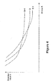
Figure 4 graphically illustrates a family of R,D curves, with one curve for each different value of quantizer Q. - Modalities to control the rate-distortion tradeoff by mode selection in video encoders are disclosed. In the following description, for purposes of explanation, specific nomenclature is set forth to provide a thorough understanding of the present invention. However, it will be apparent to one skilled in the art that these specific details are not required in order to practice the present invention. For example, the present invention has been described with reference to the MPEG-4 Part 10 (H.264) multimedia compression and encoding system. However, the same techniques can easily be applied to other types of compression and encoding systems.
-
Figure 1 illustrates a high-level block diagram of a typical digital video encoder 100 as is well known in the art. The digital video encoder 100 receivesincoming video stream 105 at the left of the block diagram. Each video frame is processed by a Discrete Cosine Transformation (DCT)unit 110. The video frame may be processed independently (an intra-frame) or with reference to information from other frames (an inter-frame) usingmotion estimation unit 160. A Quantizer (Q)unit 120 then quantizes the information from the DiscreteCosine Transformation unit 110. The quantized frame is then encoded with an entropy encoder (H)unit 180 to produce an encoded video bitstream. - Since an inter-frame encoded video frame is defined with reference to other nearby video frames, the digital video encoder 100 needs to create a copy of exactly how a referenced digital video frame will appear within a digital video decoder such that inter-frames may be encoded. Thus, the lower portion of the digital video encoder 100 is actually a digital video decoder. Specifically, Inverse quantizer (Q-1) 130 reverses the quantization of the frame information and inverse Discrete Cosine Transformation (DCT-1)
unit 140 reverses the Discrete Cosine Transformation of the video frame information. After all the DCT coefficients are reconstructed from inverse Discrete Cosine Transformation, the motion compensation unit will use the information, along with the motion vectors, to reconstruct the video frame which then may be used as a reference video frame for the motion estimation of other video frames. - The decoded video frame may be used to encode inter-frames that are defined relative to information in the decoded video frame. Specifically, a motion compensation (MC) unit 150 and a motion estimation (ME)
unit 160 are used to determine motion vectors and generate differential values used to encode inter-frames. - A
rate controller 190 receives information from many different components in a digital video encoder 100 and uses the information to allocate a bit budget for each video frame to be encoded. The bit budget should be assigned in a manner that will generate the highest quality digital video bit stream that complies with a specified set of restrictions. Specifically, therate controller 190 attempts to generate the highest quality of a compressed video stream without overflowing memory buffers (exceeding the amount of available buffer memory by sending video frame information much faster than the video frame information is displayed and subsequently deleted) or underflowing memory buffers (not sending video frame information fast enough such that a receiving digital video decoder runs out of video frame information to display). - Many digital video coding algorithms first partition each video picture into small subsets of pixels that are generally referred to as pixelblocks. Specifically, the video picture is divided into a grid of rectangular pixelblocks. The terms Mocroblock, block, sub-block are also commonly used for subsets of pixels. This document will use theterm pixelblock to include all of these different but similar constructs. Different sized pixelblocks may be used by different digital video eacoding systems. For exarsple, different pixerblock sizes used include 8 pixel by 8 pixel pixelblocks, 8 pixel by 4 pixel pixelblocks, 16 pixel by 16 pixel pixelblocks, 4 pixel by 4 pixel pixelblocks, etc.
- To encode a video picture, each individual pixelblock of the video picture is encoded using some sort of encoding method. Some pixelblocks known as iutra-blocks are encoded without reference to any other pixelblocks. Other pixelblocks are encoded using some predictive coding method such as motion compensation that refers to a closely matching pixelblock in the same or a different video picture.
- Each individual pixelblook in a video picture is independently compressed and encoded. Some video coding standards, e,g., ISO MPEG or ITU H.264. use different types of predicted pixelblocks to encode digital video pictures. In one scenario, a pixelblock may be one of three types;
- 1. 1-pixelblock -An Intra (I) pixelblock uses no information from any other video pictures in its coding (Thus, an intra-pixelblock it is completely self-defined.);
- 2. P-pixelblock-A unidirectionally Predicted (P) pixelblock refers to picture information from an earlier video picture; or
- 3. B-pixelblock - A Bi-diyectional predicted (B) pixelblock uses information from both an earlier video picture and a later future video picture.
- If all of the pixelblocks in an encoded digital video picture are Intra-pixelblocks (I-pixelblocks) then the encoded digital video picture frame is known as an Intra-frame. Note that an Intra-frame makes no reference to any other video picture such that the Intra-frame digital video picture is completely self-defined,
- If a digital video picture frame only includes unidirectional predicted pixelblocks (P-pixelblocks) and intra-pixelblocks (I-pixelblocks) but no bidirectional predicted pixelblocks (B-pixelblocks), then the video picture frame is known as a P-frame, I-pixelblocks may appear in P-frames when using predictive encoding (P-Pixelblock encoding) requires more bits than an independently encoded pixelblock (an I-pixelblork).
- If a digital video picture frame contains any bi-dinctioual predicted pixelblocks (B-pixelblocks), then the video picture frame is known as a B-frame. For the simplicity, this document will consider the case, where all pixelblocks within a given picture are of the same type. (Inta-frames only contain I-pixelblooks, P-frames only contain P-pixelblocks, and B-frmes only contain B-pixelblocks.)
- An example sequence of video pictures to be encoded might be represented as:
- I1 B2 B3 B4 B5 B6 B7 B8 B9 B10 B11 B12 B13 B14...
- The preceding example series of video pictures is conceptually illustrated in
Figure 2 . Referring toFigure 2 , the arrows indicate, that pixelblocks from a stored picture (I-frame or P-frame in this case) are used in the motion compensated prediction of other digital video pictures (B-frmes and P-frames). - Referring to
Figure 2 , no information form any other video picture is used in the encoding of the first video picture frame, intra-frame video picture I1. Video picture P5 is a P-frame that uses video information from previous video picture I1 in its encoding such that an arrow is drawn from intut-frame video picture I1 to P-frame video picture P5. Video picture B1, video picture B3, and video picture B4 all use information from both video picture I1 and video picture P5 in their encoding, such that information dependency arrows are drawn from video picture I1 and video picture P5 to video picture B2, video picture B3, and video picture B4, - Since B-frame video pictures use information from later video pictures (pictures that will be displayed later), the transmission order of a set of digital video pictures is usually different than the display order of the digital video pictures. Specifically, referenced video pictures that are needed to construct other video pictures should be transmitted before the video pictures that are dependent upon referenced video pictures. Thus, for the display order of
Figure 2 , the preferred transmission order might be: - I1 P5 B2 B3 B4 P10 B6 B7 B8 B9 P12 B11 B13...
- Referring to
Figure 3 , the transmitting system first transmits I-frame I1 which does not depend on any other video frame. Next, the system transmits P-frame video picture P5 that depends only upon previously transmitted video picture I1. Next, the system transmits B-frame video picture B2 after video picture P5 even though video picture B2 will be displayed before video picture P5. The reason for this is that when it comes time to decode and render dependent video picture B2, the digital video decoder will have already received and decoded the information in video picture I1 and video picture P5 necessary to decode dependent video picture B2. Similarly, decoded video picture I1 and decoded video picture P5 are ready to be used to decode and render the next two dependent video pictures: dependent video picture B3 and dependent video picture B4. - The receiver/decode system then reorders the video picture sequence for proper display. In this operation, referenced video picture I1 and referenced video picture P5 are referred to as "stored pictures," Stored pictures are used to reconstruct other dependent video pictures that refer to the stored pictures. (Note that some digital video encoding system also allow B-frames to be used as stored pictures.)
- The encoding of P-Pictures typically utilizes Motion Compensation (MC), wherein a Motion Vector (MV) pointing to a location in a previous video picture is computed for each pixelblock in the current video picture. The Motion Vector refers to a closely matching pixelblock in a referenced video picture. Using the motion vector, a prediction pixelblock can be formed by translation of referenced pixels in the aforementioned previous video picture. The difference between the actual pixelblock in the P-Picture and the prediction pixelblock is then coded for transmission. This difference is then used to accurately reconstruct the original pixelblock.
- Each motion vector may also be transmitted via a predictive encoding method. For example, a motion vector prediction may be formed using nearby motion vectors. In such a case, then the difference between the actual motion vector and a predicted motion vector is then coded for transmission. The difference is then used to ereate the actual motion vector from the predicted motion vector.
- Each B-pixelblock in a B-frame uses two different motion vectors: a first motion vector that references a pixelblock in an earlier video picture and a second motion vector that references another pixelblock in a later video picture. From these two motion vectors, two prediction pixelblocks are computed. The two predicted pixelblocks are then combined together, using some function, to form a final predicted pixelblock. (The two predicted pixelblocks may simply be averaged together.) As with P-pixelblocks, the difference between the actual desired pixelblock for the B-frame picture and the final predicted pixelblock is then encoded for transmission. The pixelblock difference will then used to accurately reconstruct the original desired pixelblock.
- As with P-pixelblocks, each motion vector (MV) of a B-pixelblock may also be transmitted via a predictive encoding method, Specifically, a predicted motion vector may be formed using some combination of nearby motion vectors, Them, the difference between the actual motion vector and the predicted is encoded for transmission. The difference is then used to recreate the actual motion vector from the predicted motion vector.
- However, with B-pixelblooks the opportunity exists for interpolating motion vectors from motion vectors in the collocated or nearby stored picture pixelblock. Such motion vector interpolation is carried out both in the digital video encoder and the digital video decoder. (Remember that a digital video encoder always includes a digital video decoder.)
- In some cases, the interpolated motion vector is good enough to be used without any type of correction to the interpolated motion vector. In such cases, no motion vector data need be sent. This is referred to as 'Direct Mode' in the ITU H.263 and H.264 digital video encoding standards,
- The technique of motion vector interpolation works particularly well on a series of digital video pictures from a video sequence created by a camera that is slowly panning across a stationary background. In fact, such motion vector interpolation may be good enough to be used alone. Specifically, this means that no differerential motion vector information needs be calculated or transmitted for these B-pixelblock motion vectors encoded using such motion vector interpolation.
- Within each video picture the pixelblocks may also be coded in different manners. For example, a pixelblock may be divided into smaller subblocks, with motion vectors computed and transmitted for each subblock. The shape of the subblocks may also vary and may not necessarily be square.
- Within a P-picture or B-picture, some pixelblocks may be more efficiently encoded without using motion compensation if no closely matching pixelblock can be found in the stored reference picture. Such pixelblocks would then be coded as Intra-pixelblocks (I-pixelblocks). Within a B-picture, some pixelblocks may be better coded using unidirectional motion compensation instead of bidirectional motion compensation. Thus, those pixelblocks would be coded as forward predicted pixelblocks (P-pixelblocks) or backward predicted pixelblocks depending on whether the closest matching pixelblock was found in an earlier video picture or a later video picture.
- Prior to transmission, the prediction error of a pixelblock or subblock is typically transformed by an orthogonal transform such as the Discrete Cosine Transform or an approximation thereto. The result of the transform operation is a set of transform coefficients equal in number to the number of pixels in the pixelblock or subblock being transformed. At the receiver/decoder, the received transform coefficients are inverse transformed to recover the prediction error values to be used further in the decoding. Not all the transform coefficients need be transmitted for acceptable video quality. Depending on the transmission bit-rate available, more than half or sometimes much more than half of the transform coefficients may be deleted and not transmitted. At the decoder the deleted coefficient values are replaced by zero values prior to inverse transform operation.
- Furthermore, prior to transmission the transform coefficients are typically Quantized and Entropy Coded as set forth with reference to
Figure 1 . Quantization involves representstion of the transform coefficient values by a finite subset of possible values, which reduces the accuracy of transmission. Furthermore, the quantization often forces small transform coefficient values to zero, thus further reducing the number of transform coefficients values that are transmitted. - In the quantization step, each transform coefficient value is typically divided by a quantizer step size Q and rounded to the nearest integer. For example, the original transform coefficient C may be quantized into the quantized coefficient value Cq using the formula:
- Cq = (C + Q/2)/Q truncated to an integer.
- A digital video encoder must determine the best encoding method amongst all of the possible encoding methods (or encoding modes) that will be used to encode each pixelblock in a video picture. This encoding problem is commonly known as the mode selection problem. Many ad hoc solutions have been used in various digital video encoder implemetations to address the mode selection problem. The combination of the transform coefficient deletion, the quantization of the transform coefficients that are transmitted, and the mode selection leads to a reduction of the bit rate R used for transmission. However, these bit rate R reduction techniques also lead to a distortion D in the decoded video pictures.
- Ideally, when designing a video encoder one would like to either fix the bit rote R to a constant value and minimize the coding distortion D or fix the coding distortion D to a constant value while minimizing the bit rate R. However, especially at the pixelblock level, the bit rate R and/or the distortion D value may vary considerably from the desired fixed value, thus making the constrained optimization approach untenable.
- Instead what may be done is to use a Lagrange multiplier to convert the constrained optimization problem into an unconstrained optimization problem. Thus, instead of fixing one of the variables (bit rate R or the distortion D) and optimízing the other variable, one may instead simply minimize the Lagrange function:

- In theory, a full optimization for each individual video picture would be carried out by repeatedly using all possible values of lambda, with each lambda producing a {D,R} pair. From this, for a desired bit rate R (or distortion D), the corresponding distortion D (or bit rate R) and lambda value can be found. Then the video picture would be finally encoded again using this selected lambda value, which would produce the desired result.
- In practice, this ideal approach is usually too complicated and too resource intensive to perform for every video picture. What is usually done is to carry out many preliminary experiments with many video pictures using the complete optimization method above with a wide range of lambdas in order to determine approximate relationships between lambda, distortion D, and quantizer Q.
- Preliminary experiments with a large number of video pictures using the complete optimization method with a wide range of lambdas determine approximate relationships between lambda, distortion D, and quantizer Q. In these experiments it is often advantageous to hold the quantizer Q constant while varying the lambda Lagrange multiplier. If quantizer Q is held constant during each experiment, the end result is a family of R,D curves, with one curve for each different value of quantizer Q.
Figure 4 illustrates one example of such a family of R,D curves. For each different constant Q curve, at a particular {R,D} point obtained with a certain value of lambda the slope of the curve is (-lambda). The optimum {R,D} relationship is obtained by taking the minimum of all the R,D curves. - Following this, for each different quantiser Q value, a representative lambda value is chosen such as lambdaQ. For example, lambdaQ might be the value that provides a distortion D value half-way between the crossover points for Q+1 and Q-1 in
Figure 4 . Other methods that have been used to select a representative lambda value include lambdaQ = 0.85Q2 and lambdaQ = 0.85×2Q/3, For multiple B-pictures, much larger lambdaQ values are often chosen. Thus, we have
- In many applications, the resulting bit rate R may be too large or too small necessitating the use of rate control to ensure that no buffer overflow or buffer underflow occurs. With most rate control algorithms, the usual method is to vary the quantizer Q from pixelblock to pixelblock and/or from video picture to video picture, When the encoder buffer threatens to get too full (and possibly overflow) the value of the quantizer Q is increased in order to reduce the bit rate R. When the encoder buffer is too empty (and will possibly underflow), the quantizer Q is reduced in order to increase the bit rate R.
- However, the changing of the quantizer Q value may result in too large of a change in the bit rate R. Furthermore, changes in the Quantizer Q need to be signaled to the decoder, which adds to the amount of overhead bits that must be transmitted to the decoder. Moreover, changing Quantizer Q may have other effects relating to video picture quality, such as loop filtering.
- An alternative to change the quantizer Q is to change the Lagrange multiplier lambda in order to achieve the desired rate control. A smaller value of the Lagrange multiplier lambda resets in a larger bit rate R (and smaller distortion D), and similarly a larger value of the Lagrange multiplier lambda decreases the bit rate R (and increases distortion D). The variation in the Lagrange multiplier lambda can be arbitrarily fine, as opposed to changes in the quantizer Q that is digitized and encoded such that the quantizer Q is limited to only certain values. In many digital video compression and encoding systems, including all of the MPEG video compression and encoding standards, not all integer values of the quantizer Q are allowed to be sent, in which case the abrupt change in bit rate R may be even more pronounced.
- When the Lagrange multiplier lambda is required to be larger than a certain threshold Lambda_max(Q) to achieve a certain bit rate reduction, then the quantizer Q would be increased and the Lagrange multiplier lambda would return to its nominal value f(Q) using the newly increased quantizer Q value. When the Lagrange multiplier lambda is required to be smaller than a certain threshold Lambda_min(Q) to achieve a certain bit rate increase, then the quantizer Q would be decreased and the Lagrange multiplier lambda would return to its nominal value f(Q) using the newly decreased quantizer Q.
- The values of Lambda_max(Q) and Lambda_min(Q) are determined by the crossover points on the bit rate-distortion relationship illustrated in
Figure 4 . If one defines D(lambda,Q) to be the distortion achieved when encoding with the Lagrange multiplier lambda and quantizer step size Q, then the operative relationships are
- The detailed operation of such a rate control algorithm for a video encoding system is set forth in the following pseudo code:
 Start_encoding_picture: // Begin encoding a video picture
      input desired D; // Get the desired Distortion D value
      find DQ nearest to D; // Find the DQ value closest to the desired D
      Q = h(DQ); // Determine the quantizer value Q
      lambda = f(Q); // Determine the Lagrange multiplier lambda
 start_encoding_pixelblock: // Begin encoding a pixelblock from the picture
      code_pixelblock(lambda,Q); // Encode pixelblock using lambda and Q
      if (encoder_buffer > Tfull){ // Buffer threatens to overflow?
             lambda = lambda+deltalambda; // deltalambda may depd on Q
              if (lambda > Lambda_max(Q)}{ // if lambda too large, incr Q
                     Q = Q+deltaQ; // Increase the Quantizer Q size
                     lambda = f(O); // Set new Lagrange multiplier lambda
             }
      }
      if (encoder_buffer < Ternpty){ // Buffer threatens to underflow?
             lambda=lambda-deltalambda; // Yes, so decrease lambda
             if (lambda < Lambda_rnin(Q) ){ // if lambda too small, decr Q
                     Q = Q-deltaQ; // Decrease Quantizer Q size
                     lambda = f(Q); // Set new Lagrange multiplier lambda
             }
      }
      if (not last pixelblock) then goto start_encoding_pixelblock; //Next blok
 // Done with picture.
Similarly, for the lambda decrement operation the following equation may be used
 Start_encoding_picture: // Begin encoding a video picture
      input desired D: // Get the desired Distortion D value
     find DQ nearest to D; // Find the D value closes to the desired D
      Qnorm = h(DQ); // Determine normal Q with no masking
     lambda = f(Qnorm); // Determine the Lagrange multiplier lambda
 stsrt_encoding_pixelblock: // Begin encoding a pixelblock from the picture
     Q = Qnorm; // Set Q to the normal Q with no masking
     calculate visual mask M; // Determine the visual masking amount
     while(Mxlambda > Lambda_max(Q) ){// if strong masking, increase Q
             Q = Q+deltaQ; // Raise the Quantizer Q size
     code pixelblock(Mxlambda, Q); // Encode using Mxlambda and Q
     if (encoder_buffer > Tfull){ // If buffer threatens to fill overflow
             lambda = lambda+deltalambda; // Increase lambda
             if (lambda > Lambda_max(Qnorm){ // Test lambda
                    Qnorm=Qnorm+deltaQ; //Increase Q if lambda too big
                    lambda = f(Qnorm); // Calculate new lambda
             }
     }
     if (encoder_buffer < Tempty){ // If buffer threatens to fill underflow
             lambda = lambda-deltalambda; // Decrease lambda
             if (lambda < Lambda_min(Qnorm) ){ // Test lambda
                    Qnorm = Qnorm-deltaQ; // Decr Q if lambda too small
                    lambda = f(Qnorm); // Calculate new lambda
             }
     }
     if (not last pixelblock) then goto start_encoding_pixelblock //Next
 // Done with picture.
This second simple visual masking algorithm illustrates the use of varying, lambda for this application, Other more complicated visual masking algorithms have also been devised, and those visual masking algorithms could also benefit from varying lambda.
-
Item 1. A method of controlling rate distortion in a video compression and encoding system, said method comprising:- selecting a distortion value D near a desired distortion value;
- determining a quantizer value Q using said distortion value D;
- calculating a Lagrange multiplier lambda using said quantizer value Q; and
- encoding a pixelblock using said Lagrange multiplier lambda and said quantizer value Q.
- Item 2. The method of
item 1, said method further comprising:- increasing said Lagrange multiplier lambda when a buffer exceeds an overflow threshold value and increasing said quantizer value Q if said Lagrange multiplier lambda exceeds a maximum lambda threshold; and
- decreasing said Lagrange multiplier lambda when a buffer falls below an undererflow threshold value and decreasing said quantizer value Q if said Lagrange multiplier lambda falls below a minimum lambda threshold.
- Item 3. The method of item 2, said method further comprising:
- recalculating said Lagrange multiplier lambda if said quantizer value Q is adjusted.
- Item 4. The method of item 2, said method further comprising wherein said Lagrange multiplier lambda is increased or decreased by an amount dependent upon said quantizer value Q,
- Item 5. The method of
item 1, said method further comprising:- calculating a visual mask value M; and
- increasing said Lagrange multiplier lambda when said visual mask value M times said Lagrange multiplier lambda is less than a maximum threshold for said Lagrange multiplier lambda.
- Item 6. The method of item 5 wherein said maximum threshold for said Lagrange multiplier lambda is dependent upon said quantizer value Q.
- Item 7. The method of item 5, said method further comprising:
- increasing said Lagrange multiplier lambda when a buffer exceeds an overflow threshold value and increasing said quantizer value Q if said Lagrange multiplier lambda exceeds a maximum lambda threshold; and
- decreasing said Lagrange multiplier lambda when a buffer falls below an undererflow threshold value and decreasing said quantizer value Q if said Lagrange multiplier lambda falls below a minimum lambda threshold.
- Item 8. The method of item 7, said method further comprising:
- recalculating said Lagrange multiplier lambda if said quantizer value Q is adjusted.
- Item 9. A computer-readable medium, said computer-readable medium containing a set of computer instructions for implementing a method of controlling rate distortion in a video compression and encoding system with the following steps:
- selecting a distortion value D near a desired distortion value;
- determining a quantizer value Q using said distortion value D;
- calculating a Lagrange multiplier lambda using said quantizer value Q; and encoding a pixelblock using said Lagrange multiplier lambda and said quantizer value Q.
- Item 10. The computer-readable medium of item 9 wherein said set of computer instructions further implement the steps of:
- increasing said Lagrange multiplier lambda when a buffer exceeds an overflow threshold value and increasing said quantizer value Q if said Lagrange multiplier lambda exceeds a maximum lambda threshold; and
- decreasing said Lagrange multiplier lambda when a buffer falls below an undererflow threshold value and decreasing said quantizer value Q if said Lagrangs multiplier lambda falls below a minimum lambda threshold.
- Item 11. The computer-readable medium of item 10 wherein said set of computer instructions further implement the steps of:
- recalculating said Lagrange multiplier lambda if said quantizer value Q is adjusted.
-
Item 12. The computer-readable medium of item 10 wherein said Lagrange multiplier lambda is increased or decreased by an amount dependent upon said quantizer value Q. - Item 13. The computer-readable medium of item 9 wherein said set of computer instructions further implement the steps of:
- calculating a visual mask value M; and
- increasing said Lagrange multiplier lambda when said visual mask value M times said Lagrange multiplier lambda is less than a maximum threshold for said Lagrange multiplier lambda.
- Item 14. The computer-readable medium of item 13 wherein said maximum threshold for said L-agrage multiplier lambda is dependent upon said quantizer value Q.
- Item 15. The computer-readable medium of item 13 wherein said set of computer inactions further implement the steps of:
- increasing said Lagrange multiplier lambda when a butter exceeds an overflow threshold value and increasing said quantizer value Q if said Lagrange multiplier lambda exceeds a maximum lambda threshold; and
- decreasing said Lagrange multiplier lambda when a buffer falls below an undererflow threshold value and decreasing said quantizer value Q if said Lagrange multiplier lambda falls below a minimum lambda threshold.
- Item 16. The computer-readable medium of item 15 wherein said set of computer instructions further implement the steps of:
- recalculating said Lagrange multiplier lambda if said quantizer value Q is adjusted.
- 1. A method for controlling rate distortion, the method comprising:
- a. encoding at least one video picture based on an initial quantizer value and an initial Lagrange multiplier; and
- b. adjusting the encoding of the video picture by changing the initial quantizer value or the initial Lagrange multiplier.
- 2. The method of
clause 1, wherein the initial quantizer value and the initial Lagrange multiplier are adjusted to achieve a particular distortion value. - 3. The method of clause 2, wherein the particular distortion value is a distortion value that is closest to a desired distortion value.
- 4. The method of
clause 1, wherein adjusting the encoding is based on a buffer flow criteria. - 5. The method of
clause 1, wherein adjusting the encoding is performed when a buffer exceeds an overflow threshold value. - 6. The method of
clause 1, wherein adjusting the encoding is performed when a buffer falls under an underflow threshold value. - 7. The method of clause I, wherein the initial quantizer value is changed when the first Lagrange multiplier is above a maximum threshold value.
- 8. The method of
clause 1, wherein adjusting the encoding comprises increasing the initial Lagrange multiplier to decrease a bit rate value. - 9. The method of
clause 1, wherein adjusting the encoding comprises decreasing the initial Lagrange multiplier to increase a bit rate value. - 10. The method of
clause 1, wherein adjusting the encoding comprises increasing the initial quantizer value to decrease a bit rate value. - 11. The method of
clause 1, wherein adjusting the encoding comprises decreasing the initial quantizer value to increase a bit rate value. - 12. The method of
clause 1, wherein adjusting the encoding comprises changing the Lagrange multiplier by a particular Lagrange delta value from a plurality of Lagrange delta values. - 13. The method of
clause 12, wherein the particular Lagrange delta value that is used is based on a particular quantizer value that is used from a plurality of quantizer values. - 14. The method of
clause 1, wherein adjusting the encoding comprises changing the quantizer value by a particular quantizer delta value from a plurality of quantizer delta values. - 15. The method of clause 14, wherein the particular quantizer delta value that is used is based on a particular quantizer value that is used from a plurality of quantizer values.
- 16. The method of
clause 1, wherein adjusting the encoding comprises changing the initial Lagrange multiplier by a particular Lagrange delta value that is multiplied by a particular multiplication factor. - 17. A method for controlling rate distortion, the method comprising:
- a. computing a visual mask value for at least one video picture; and
- b. encoding at least one video picture based on the computed visual mask value.
- 18. The method of clause 17, wherein encoding is further based on a quantizer value and a Lagrange multiplier.
- 19. The method of clause 18 further comprising adjusting the encoding of me video picture by changing the quantizer value.
- 20. The method of clause 19, wherein the quantizer value is changed when the visual mask value multiplied by the Lagrange multiplier is greater than a threshold value.
- 21. The method of clause 18 further comprising adjusting the encoding of the video picture by changing the Lagrange multiplier.
- 22. The method of clause 21, wherein the Lagrange multiplier is changed by a Lagrange delta value that is multiplier by the visual mask value.
- 23. The method of clause 17, wherein the visual mask value defines a visibility of encoding noise for at least one video picture.
- 24. The method of clause 17, wherein the visual mask value is based on spatial variations of at least one pixel within a region of a video picture.
- 25. The method of clause 17, wherein the visual mask value is based on temporal variations of at least one pixel within a region of a video picture.
- 26. A computer readable medium storing a computer program that is executable by at least one processor, the computer program comprising sets of instructions for implementing the method according to any of clauses 1-25.
- 27. An encoder comprising:
- a. a quantizer unit for quantizing at least one video picture; and
- b. a rate controller for changing a Lagrange multiplier and a quantizer value that is used by the quantizer unit.
- 28. The encoder of clause 27, wherein the Lagrange multiplier is changed before the quantizer value is changed.
- 29. The encoder of clause 27 further comprising a buffer for storing video pictures.
- 30. The encoder of clause 27, wherein the rate controller changes the Lagrange multiplier when a buffer is above a threshold value.
- 31. The encoder of clause 27, wherein the rate controller changes the Lagrange multiplier when a buffer is below a threshold value.
- 32. The encoder of clause 27, wherein the rate controller changes the quantizer value when a buffer is above a threshold value.
- 33. The encoder of clause 27, wherein the rate controller changes the quantizer value when a buffer is below a threshold value.
- 34. The encoder of clause 27, wherein the rate controller is farther for computing a visual mask value for at least one video picture.
Claims (9)
- A method for controlling bit rate for encoding of a plurality of video pictures, the method comprising:setting a first quantizer value as a specified quantizer value for encoding at least one video picture, said first quantizer value associated with a Lagrange multiplier value;computing a visual mask value for said at least one video picture, said visual mask value defining a visibility of encoding noise for at least said one video picture;when the visual mask value multiplied by the Lagrange multiplier value satisfies a Lagrange multiplier threshold value, setting a second quantizer value as the specified quantizer value used for encoding said at least one video picture; andencoding at least one video picture based on the specified quantizer value.
- The method of claim 1 further comprising adjusting the encoding of the at least one video picture by changing the Lagrange multiplier.
- The method of claim 1 further comprising adjusting the encoding of the at least one video picture by changing the specified quantizer value.
- The method of claim 1, wherein the visual mask value multiplied by the Lagrange multiplier value satisfies the Lagrange multiplier threshold value when the visual mask value multiplied by the Lagrange multiplier value is greater than the Lagrange multiplier threshold value.
- The method of claim 1, wherein encoding said at least one video picture is further based on another Lagrange multiplier value for the specified quantizer value.
- The method of claim 1, wherein setting the second quantizer value comprises changing the first quantizer value by a quantizer delta value.
- The method of claim 1, wherein the visual mask value is based on spatial variations of at least one pixel within a region of a video picture.
- The method of claim 1, wherein the visual mask value is based on temporal variations of at least one pixel within a region of a video picture.
- A computer readable medium storing a computer program that is executable by at least one processor, the computer program comprising sets of instructions for implementing the method according to any of claims 1-8.
Applications Claiming Priority (4)
| Application Number | Priority Date | Filing Date | Title |
|---|---|---|---|
| US42473802P | 2002-11-08 | 2002-11-08 | |
| US10/615,117 US7042943B2 (en) | 2002-11-08 | 2003-07-07 | Method and apparatus for control of rate-distortion tradeoff by mode selection in video encoders |
| EP08005751A EP1933569A3 (en) | 2002-11-08 | 2003-10-31 | Method and apparatus for control of rate-distortion tradeoff by using lagrange multiplier and/or quantizer value |
| EP03778014A EP1563688B1 (en) | 2002-11-08 | 2003-10-31 | Method and apparatus for control of rate-distortion tradeoff by using lagrange multiplier and visual mask |
Related Parent Applications (2)
| Application Number | Title | Priority Date | Filing Date |
|---|---|---|---|
| EP03778014.5 Division | 2003-10-31 | ||
| EP08005751.6 Division | 2008-03-27 |
Publications (2)
| Publication Number | Publication Date |
|---|---|
| EP2271104A2 true EP2271104A2 (en) | 2011-01-05 |
| EP2271104A3 EP2271104A3 (en) | 2012-06-06 |
Family
ID=32314552
Family Applications (2)
| Application Number | Title | Priority Date | Filing Date |
|---|---|---|---|
| EP03778014A Expired - Lifetime EP1563688B1 (en) | 2002-11-08 | 2003-10-31 | Method and apparatus for control of rate-distortion tradeoff by using lagrange multiplier and visual mask |
| EP10179164A Withdrawn EP2271104A3 (en) | 2002-11-08 | 2003-10-31 | Method and apparatus for control of rate-distortion tradeoff by using Lagrange multiplier and visual mask |
Family Applications Before (1)
| Application Number | Title | Priority Date | Filing Date |
|---|---|---|---|
| EP03778014A Expired - Lifetime EP1563688B1 (en) | 2002-11-08 | 2003-10-31 | Method and apparatus for control of rate-distortion tradeoff by using lagrange multiplier and visual mask |
Country Status (7)
| Country | Link |
|---|---|
| US (3) | US7042943B2 (en) |
| EP (2) | EP1563688B1 (en) |
| JP (2) | JP4480671B2 (en) |
| AT (1) | ATE493845T1 (en) |
| AU (1) | AU2003286800A1 (en) |
| DE (1) | DE60335567D1 (en) |
| WO (1) | WO2004045218A1 (en) |
Cited By (5)
| Publication number | Priority date | Publication date | Assignee | Title |
|---|---|---|---|---|
| US8208536B2 (en) | 2005-04-28 | 2012-06-26 | Apple Inc. | Method and apparatus for encoding using single pass rate controller |
| US8355436B2 (en) | 2002-11-08 | 2013-01-15 | Apple Inc. | Method and apparatus for control of rate-distortion tradeoff by mode selection in video encoders |
| US8406293B2 (en) | 2004-06-27 | 2013-03-26 | Apple Inc. | Multi-pass video encoding based on different quantization parameters |
| US8594190B2 (en) | 2004-06-27 | 2013-11-26 | Apple Inc. | Encoding with visual masking |
| US8781002B2 (en) | 2003-01-08 | 2014-07-15 | Apple Inc. | Method and apparatus for improved coding mode selection |
Families Citing this family (40)
| Publication number | Priority date | Publication date | Assignee | Title |
|---|---|---|---|---|
| US6263503B1 (en) | 1999-05-26 | 2001-07-17 | Neal Margulis | Method for effectively implementing a wireless television system |
| US8266657B2 (en) | 2001-03-15 | 2012-09-11 | Sling Media Inc. | Method for effectively implementing a multi-room television system |
| US7769756B2 (en) | 2004-06-07 | 2010-08-03 | Sling Media, Inc. | Selection and presentation of context-relevant supplemental content and advertising |
| CA2569610C (en) | 2004-06-07 | 2012-11-27 | Sling Media, Inc. | Personal media broadcasting system |
| US7917932B2 (en) | 2005-06-07 | 2011-03-29 | Sling Media, Inc. | Personal video recorder functionality for placeshifting systems |
| US7975062B2 (en) | 2004-06-07 | 2011-07-05 | Sling Media, Inc. | Capturing and sharing media content |
| US9998802B2 (en) | 2004-06-07 | 2018-06-12 | Sling Media LLC | Systems and methods for creating variable length clips from a media stream |
| WO2005125213A1 (en) * | 2004-06-15 | 2005-12-29 | Ntt Docomo, Inc. | Apparatus and method for generating a transmit frame |
| US7627781B2 (en) * | 2004-10-25 | 2009-12-01 | Hewlett-Packard Development Company, L.P. | System and method for establishing a spare processor for recovering from loss of lockstep in a boot processor |
| US7447337B2 (en) * | 2004-10-25 | 2008-11-04 | Hewlett-Packard Development Company, L.P. | Video content understanding through real time video motion analysis |
| US7818614B2 (en) * | 2004-10-25 | 2010-10-19 | Hewlett-Packard Development Company, L.P. | System and method for reintroducing a processor module to an operating system after lockstep recovery |
| US7624302B2 (en) * | 2004-10-25 | 2009-11-24 | Hewlett-Packard Development Company, L.P. | System and method for switching the role of boot processor to a spare processor responsive to detection of loss of lockstep in a boot processor |
| US20060117355A1 (en) * | 2004-11-29 | 2006-06-01 | Vincent Dureau | Pushing content in a two-way network |
| US7675872B2 (en) * | 2004-11-30 | 2010-03-09 | Broadcom Corporation | System, method, and apparatus for displaying pictures |
| US9479794B2 (en) | 2005-11-10 | 2016-10-25 | Freescale Semiconductor, Inc. | Resource efficient video processing via prediction error computational adjustments |
| US8077775B2 (en) | 2006-05-12 | 2011-12-13 | Freescale Semiconductor, Inc. | System and method of adaptive rate control for a video encoder |
| US7773672B2 (en) | 2006-05-30 | 2010-08-10 | Freescale Semiconductor, Inc. | Scalable rate control system for a video encoder |
| US8135063B2 (en) * | 2006-09-08 | 2012-03-13 | Mediatek Inc. | Rate control method with frame-layer bit allocation and video encoder |
| US9883202B2 (en) | 2006-10-06 | 2018-01-30 | Nxp Usa, Inc. | Scaling video processing complexity based on power savings factor |
| US8731070B2 (en) * | 2006-12-15 | 2014-05-20 | Thomson Licensing | Hybrid look-ahead and look-back distortion estimation |
| WO2008111454A1 (en) * | 2007-03-14 | 2008-09-18 | Nippon Telegraph And Telephone Corporation | Quantization control method, device, program, and recording medium containing the program |
| US8265142B2 (en) * | 2007-03-14 | 2012-09-11 | Nippon Telegraph And Telephone Corporation | Encoding bit-rate control method and apparatus, program therefor, and storage medium which stores the program |
| KR101083379B1 (en) * | 2007-03-14 | 2011-11-14 | 니폰덴신뎅와 가부시키가이샤 | Motion vector searching method and device, and record medium having recorded the program therefor |
| RU2420911C1 (en) * | 2007-03-14 | 2011-06-10 | Ниппон Телеграф Энд Телефон Корпорейшн | Apparatus and method of estimating code volume, as well as data medium for implementing said method |
| WO2010032419A1 (en) * | 2008-09-18 | 2010-03-25 | パナソニック株式会社 | Image decoding device, image encoding device, image decoding method, image encoding method, and program |
| KR101377530B1 (en) | 2009-08-21 | 2014-03-27 | 에스케이텔레콤 주식회사 | Video Coding Method and Apparatus by Using Adaptive Motion Vector Resolution |
| WO2011021914A2 (en) | 2009-08-21 | 2011-02-24 | 에스케이텔레콤 주식회사 | Method and apparatus for encoding/decoding images using adaptive motion vector resolution |
| US8238444B2 (en) * | 2009-12-15 | 2012-08-07 | National Taiwan University | Perceptual-based video coding method |
| WO2011072893A1 (en) * | 2009-12-16 | 2011-06-23 | International Business Machines Corporation | Video coding using pixel-streams |
| CA2837755C (en) * | 2011-06-01 | 2019-04-09 | Zhou Wang | Method and system for structural similarity based perceptual video coding |
| WO2013087793A1 (en) * | 2011-12-14 | 2013-06-20 | Tp Vision Holding B.V. | Streaming video data having adaptable bit rate |
| US10230956B2 (en) * | 2012-09-26 | 2019-03-12 | Integrated Device Technology, Inc. | Apparatuses and methods for optimizing rate-distortion of syntax elements |
| US9866853B2 (en) * | 2014-04-15 | 2018-01-09 | Qualcomm Incorporated | System and method for lagrangian parameter calculation for display stream compression (DSC) |
| US10013625B1 (en) * | 2014-04-16 | 2018-07-03 | Instart Logic, Inc. | QoE-driven unsupervised image categorization for optimized web delivery |
| CN104301724B (en) | 2014-10-17 | 2017-12-01 | 华为技术有限公司 | Method for processing video frequency, encoding device and decoding device |
| US10015503B1 (en) | 2015-09-24 | 2018-07-03 | Instart Logic, Inc. | Fast, real-time, estimation of content-sensitive encoding quality for optimized web delivery of images |
| US10511853B2 (en) * | 2016-11-24 | 2019-12-17 | Ecole De Technologie Superieure | Method and system for parallel rate-constrained motion estimation in video coding |
| US10291936B2 (en) | 2017-08-15 | 2019-05-14 | Electronic Arts Inc. | Overcoming lost or corrupted slices in video streaming |
| CN115280772B (en) * | 2020-04-08 | 2025-07-22 | 谷歌有限责任公司 | Lossy compressed double standard block segmentation heuristic |
| CN115428451B (en) * | 2020-07-31 | 2024-12-27 | Oppo广东移动通信有限公司 | Video encoding method, encoder, system, and computer storage medium |
Citations (1)
| Publication number | Priority date | Publication date | Assignee | Title |
|---|---|---|---|---|
| US5691770A (en) | 1995-04-25 | 1997-11-25 | U.S. Philips Corporation | Device and method for coding video pictures |
Family Cites Families (49)
| Publication number | Priority date | Publication date | Assignee | Title |
|---|---|---|---|---|
| JPH0595536A (en) | 1991-10-01 | 1993-04-16 | Toshiba Corp | High efficiency coded signal processor |
| US5592302A (en) * | 1992-03-23 | 1997-01-07 | Canon Kabushiki Kaisha | Coding method for coding pixel blocks and apparatus therefor |
| KR0150955B1 (en) | 1992-05-27 | 1998-10-15 | 강진구 | Compressive and extensive method of an image for bit-fixing and the apparatus thereof |
| JP3133517B2 (en) | 1992-10-15 | 2001-02-13 | シャープ株式会社 | Image region detecting device, image encoding device using the image detecting device |
| US5473384A (en) | 1993-12-16 | 1995-12-05 | At&T Corp. | Method of and system for enhancing distorted graphical information |
| WO1996008922A1 (en) | 1994-09-13 | 1996-03-21 | Philips Electronics N.V. | Storage and retrieval of a data reduced digital video signal in/from a memory and recording and reproduction of a data reduced digital video signal on a longitudinal record carrier |
| DE69609137T2 (en) | 1995-04-25 | 2001-03-01 | Koninklijke Philips Electronics N.V., Eindhoven | DEVICE AND METHOD FOR ENCODING VIDEO IMAGES. |
| US5778192A (en) * | 1995-10-26 | 1998-07-07 | Motorola, Inc. | Method and device for optimal bit allocation between different sources of information in digital video compression |
| US5872598A (en) | 1995-12-26 | 1999-02-16 | C-Cube Microsystems | Scene change detection using quantization scale factor rate control |
| US5801779A (en) | 1995-12-26 | 1998-09-01 | C-Cube Microsystems, Inc. | Rate control with panic mode |
| US5929916A (en) * | 1995-12-26 | 1999-07-27 | Legall; Didier J. | Variable bit rate encoding |
| US5867221A (en) | 1996-03-29 | 1999-02-02 | Interated Systems, Inc. | Method and system for the fractal compression of data using an integrated circuit for discrete cosine transform compression/decompression |
| US5790131A (en) | 1996-05-15 | 1998-08-04 | Iterated Systems, Inc. | System and method for lossy compression of data with output file size control |
| US6101276A (en) | 1996-06-21 | 2000-08-08 | Compaq Computer Corporation | Method and apparatus for performing two pass quality video compression through pipelining and buffer management |
| FR2753330B1 (en) | 1996-09-06 | 1998-11-27 | Thomson Multimedia Sa | QUANTIFICATION METHOD FOR VIDEO CODING |
| US6111991A (en) * | 1998-01-16 | 2000-08-29 | Sharp Laboratories Of America | Method and apparatus for optimizing quantizer values in an image encoder |
| FR2764156B1 (en) | 1997-05-27 | 1999-11-05 | Thomson Broadcast Systems | PRETREATMENT DEVICE FOR MPEG II CODING |
| US6023296A (en) | 1997-07-10 | 2000-02-08 | Sarnoff Corporation | Apparatus and method for object based rate control in a coding system |
| JP2001501430A (en) | 1997-07-29 | 2001-01-30 | コーニンクレッカ フィリップス エレクトロニクス エヌ ヴィ | Variable bit rate video encoding method and corresponding video encoder |
| US6192075B1 (en) | 1997-08-21 | 2001-02-20 | Stream Machine Company | Single-pass variable bit-rate control for digital video coding |
| WO1999022525A1 (en) | 1997-10-23 | 1999-05-06 | Mitsubishi Denki Kabushiki Kaisha | Image encoding method, image encoder, image decoding method, and image decoder |
| US6278735B1 (en) | 1998-03-19 | 2001-08-21 | International Business Machines Corporation | Real-time single pass variable bit rate control strategy and encoder |
| US6826228B1 (en) | 1998-05-12 | 2004-11-30 | Stmicroelectronics Asia Pacific (Pte) Ltd. | Conditional masking for video encoder |
| US6259733B1 (en) | 1998-06-16 | 2001-07-10 | General Instrument Corporation | Pre-processing of bit rate allocation in a multi-channel video encoder |
| US6289129B1 (en) | 1998-06-19 | 2001-09-11 | Motorola, Inc. | Video rate buffer for use with push dataflow |
| CN1184820C (en) | 1999-01-15 | 2005-01-12 | 皇家菲利浦电子有限公司 | Coding and Noise Filtering Image Sequences |
| US6414992B1 (en) * | 1999-01-27 | 2002-07-02 | Sun Microsystems, Inc. | Optimal encoding of motion compensated video |
| WO2000049570A1 (en) | 1999-02-19 | 2000-08-24 | Unisearch Limited | Method for visual optimisation of embedded block codes to exploit visual masking phenomena |
| US6493386B1 (en) | 2000-02-02 | 2002-12-10 | Mitsubishi Electric Research Laboratories, Inc. | Object based bitstream transcoder |
| US6490320B1 (en) | 2000-02-02 | 2002-12-03 | Mitsubishi Electric Research Laboratories Inc. | Adaptable bitstream video delivery system |
| US6574279B1 (en) | 2000-02-02 | 2003-06-03 | Mitsubishi Electric Research Laboratories, Inc. | Video transcoding using syntactic and semantic clues |
| US20040064414A1 (en) * | 2000-06-30 | 2004-04-01 | Kia Silverbrook | Method and system for banking coded self-identifying forms |
| US6650707B2 (en) | 2001-03-02 | 2003-11-18 | Industrial Technology Research Institute | Transcoding apparatus and method |
| US6687294B2 (en) | 2001-04-27 | 2004-02-03 | Koninklijke Philips Electronics N.V. | Distortion quantizer model for video encoding |
| US6975680B2 (en) | 2001-07-12 | 2005-12-13 | Dolby Laboratories, Inc. | Macroblock mode decision biasing for video compression systems |
| EP1296524A1 (en) | 2001-09-20 | 2003-03-26 | STMicroelectronics S.r.l. | Process and apparatus for the compression of digital video signals, a system and a computer program product therefor |
| EP1347649A1 (en) | 2002-03-18 | 2003-09-24 | Lg Electronics Inc. | B picture mode determining method and apparatus in video coding system |
| KR100468726B1 (en) | 2002-04-18 | 2005-01-29 | 삼성전자주식회사 | Apparatus and method for performing variable bit rate control in real time |
| CA2491522C (en) | 2002-07-01 | 2014-12-09 | E G Technology Inc. | Efficient compression and transport of video over a network |
| US7042943B2 (en) | 2002-11-08 | 2006-05-09 | Apple Computer, Inc. | Method and apparatus for control of rate-distortion tradeoff by mode selection in video encoders |
| EP1933569A3 (en) | 2002-11-08 | 2010-07-07 | Apple Inc. | Method and apparatus for control of rate-distortion tradeoff by using lagrange multiplier and/or quantizer value |
| JP2004166128A (en) | 2002-11-15 | 2004-06-10 | Pioneer Electronic Corp | Method, device and program for coding image information |
| US7194035B2 (en) | 2003-01-08 | 2007-03-20 | Apple Computer, Inc. | Method and apparatus for improved coding mode selection |
| EP1936995A3 (en) | 2003-01-08 | 2011-01-19 | Apple Inc. | Method and apparatus for improved coding mode selection |
| JP2004230916A (en) * | 2003-01-28 | 2004-08-19 | Kasai Kogyo Co Ltd | Module structure in roof trim |
| US7095784B2 (en) | 2003-04-14 | 2006-08-22 | Silicon Intergrated Systems Corp. | Method and apparatus for moving picture compression rate control using bit allocation with initial quantization step size estimation at picture level |
| US7697608B2 (en) | 2004-02-03 | 2010-04-13 | Sony Corporation | Scalable MPEG video/macro block rate control |
| CN102833539B (en) | 2004-06-27 | 2015-03-25 | 苹果公司 | Multi-pass video encoding |
| US8406293B2 (en) | 2004-06-27 | 2013-03-26 | Apple Inc. | Multi-pass video encoding based on different quantization parameters |
-
2003
- 2003-07-07 US US10/615,117 patent/US7042943B2/en not_active Expired - Fee Related
- 2003-10-31 AU AU2003286800A patent/AU2003286800A1/en not_active Abandoned
- 2003-10-31 EP EP03778014A patent/EP1563688B1/en not_active Expired - Lifetime
- 2003-10-31 AT AT03778014T patent/ATE493845T1/en not_active IP Right Cessation
- 2003-10-31 EP EP10179164A patent/EP2271104A3/en not_active Withdrawn
- 2003-10-31 DE DE60335567T patent/DE60335567D1/en not_active Expired - Lifetime
- 2003-10-31 JP JP2005507064A patent/JP4480671B2/en not_active Expired - Fee Related
- 2003-10-31 WO PCT/US2003/034659 patent/WO2004045218A1/en not_active Ceased
-
2006
- 2006-01-30 US US11/344,591 patent/US7822118B2/en not_active Expired - Fee Related
-
2008
- 2008-01-15 JP JP2008005615A patent/JP5021502B2/en not_active Expired - Fee Related
-
2010
- 2010-06-07 US US12/795,650 patent/US8355436B2/en not_active Expired - Fee Related
Patent Citations (1)
| Publication number | Priority date | Publication date | Assignee | Title |
|---|---|---|---|---|
| US5691770A (en) | 1995-04-25 | 1997-11-25 | U.S. Philips Corporation | Device and method for coding video pictures |
Non-Patent Citations (1)
| Title |
|---|
| YANG, RATE-DISTORTION OPTIMIZATIONS FOR REGION AND OBJECT BASED WAVELET VIDEO CODING |
Cited By (6)
| Publication number | Priority date | Publication date | Assignee | Title |
|---|---|---|---|---|
| US8355436B2 (en) | 2002-11-08 | 2013-01-15 | Apple Inc. | Method and apparatus for control of rate-distortion tradeoff by mode selection in video encoders |
| US8781002B2 (en) | 2003-01-08 | 2014-07-15 | Apple Inc. | Method and apparatus for improved coding mode selection |
| US8406293B2 (en) | 2004-06-27 | 2013-03-26 | Apple Inc. | Multi-pass video encoding based on different quantization parameters |
| US8594190B2 (en) | 2004-06-27 | 2013-11-26 | Apple Inc. | Encoding with visual masking |
| US8811475B2 (en) | 2004-06-27 | 2014-08-19 | Apple Inc. | Multi-pass video encoding solution for buffer underflow |
| US8208536B2 (en) | 2005-04-28 | 2012-06-26 | Apple Inc. | Method and apparatus for encoding using single pass rate controller |
Also Published As
| Publication number | Publication date |
|---|---|
| US20040184546A1 (en) | 2004-09-23 |
| EP1563688A1 (en) | 2005-08-17 |
| AU2003286800A1 (en) | 2004-06-03 |
| JP2006506032A (en) | 2006-02-16 |
| US20060193382A1 (en) | 2006-08-31 |
| JP2008160864A (en) | 2008-07-10 |
| US8355436B2 (en) | 2013-01-15 |
| EP1563688B1 (en) | 2010-12-29 |
| JP4480671B2 (en) | 2010-06-16 |
| US7042943B2 (en) | 2006-05-09 |
| HK1076219A1 (en) | 2006-01-06 |
| EP2271104A3 (en) | 2012-06-06 |
| WO2004045218A1 (en) | 2004-05-27 |
| DE60335567D1 (en) | 2011-02-10 |
| US7822118B2 (en) | 2010-10-26 |
| ATE493845T1 (en) | 2011-01-15 |
| JP5021502B2 (en) | 2012-09-12 |
| US20100329333A1 (en) | 2010-12-30 |
Similar Documents
| Publication | Publication Date | Title |
|---|---|---|
| EP1563688B1 (en) | Method and apparatus for control of rate-distortion tradeoff by using lagrange multiplier and visual mask | |
| US8599930B2 (en) | Image coding and decoding method and apparatus considering human visual characteristics | |
| US6658157B1 (en) | Method and apparatus for converting image information | |
| EP1445958A1 (en) | Quantization method and system, for instance for video MPEG applications, and computer program product therefor | |
| US6687296B1 (en) | Apparatus and method for transforming picture information | |
| EP1584200A2 (en) | Method and apparatus for improved coding mode selection | |
| KR20010043395A (en) | Method and apparatus for reducing breathing artifacts in compressed video | |
| KR100850810B1 (en) | Variable Accuracy Inter-Picture Timing Method and Device for Digital Video Coding | |
| EP1933569A2 (en) | Method and apparatus for control of rate-distortion tradeoff by using lagrange multiplier and/or quantizer value | |
| CN1708991B (en) | Method and apparatus for controlling rate-distortion tradeoff using lagrange multiplier and visual masking | |
| HK1076219B (en) | Method and apparatus for control of rate-distortion tradeoff by using lagrange multiplier and visual mask | |
| HK1119337A (en) | Method and apparatus for control of rate-distortion tradeoff by using lagrange multiplier and/or quantizer value | |
| JP2001145108A (en) | Image information conversion apparatus and method |
Legal Events
| Date | Code | Title | Description |
|---|---|---|---|
| PUAI | Public reference made under article 153(3) epc to a published international application that has entered the european phase |
Free format text: ORIGINAL CODE: 0009012 |
|
| 17P | Request for examination filed |
Effective date: 20100924 |
|
| AC | Divisional application: reference to earlier application |
Ref document number: 1563688 Country of ref document: EP Kind code of ref document: P Ref document number: 1933569 Country of ref document: EP Kind code of ref document: P |
|
| AK | Designated contracting states |
Kind code of ref document: A2 Designated state(s): AT BE BG CH CY CZ DE DK EE ES FI FR GB GR HU IE IT LI LU MC NL PT RO SE SI SK TR |
|
| RIN1 | Information on inventor provided before grant (corrected) |
Inventor name: DUMITRAS, ADRIANA Inventor name: PURI, ATUL Inventor name: HASKELL, BARIN |
|
| PUAL | Search report despatched |
Free format text: ORIGINAL CODE: 0009013 |
|
| AK | Designated contracting states |
Kind code of ref document: A3 Designated state(s): AT BE BG CH CY CZ DE DK EE ES FI FR GB GR HU IE IT LI LU MC NL PT RO SE SI SK TR |
|
| RIC1 | Information provided on ipc code assigned before grant |
Ipc: H04N 7/50 20060101ALI20120427BHEP Ipc: H04N 7/30 20060101AFI20120427BHEP Ipc: H04N 7/26 20060101ALI20120427BHEP |
|
| 17Q | First examination report despatched |
Effective date: 20141007 |
|
| STAA | Information on the status of an ep patent application or granted ep patent |
Free format text: STATUS: THE APPLICATION IS DEEMED TO BE WITHDRAWN |
|
| 18D | Application deemed to be withdrawn |
Effective date: 20150218 |