EP2271007A1 - Gleichzeitige Übertragung in einem Gleichwellennetz - Google Patents
Gleichzeitige Übertragung in einem Gleichwellennetz Download PDFInfo
- Publication number
- EP2271007A1 EP2271007A1 EP10012175A EP10012175A EP2271007A1 EP 2271007 A1 EP2271007 A1 EP 2271007A1 EP 10012175 A EP10012175 A EP 10012175A EP 10012175 A EP10012175 A EP 10012175A EP 2271007 A1 EP2271007 A1 EP 2271007A1
- Authority
- EP
- European Patent Office
- Prior art keywords
- signal
- transmitter
- transmitted
- frame
- packets
- Prior art date
- Legal status (The legal status is an assumption and is not a legal conclusion. Google has not performed a legal analysis and makes no representation as to the accuracy of the status listed.)
- Granted
Links
Images


Classifications
-
- H—ELECTRICITY
- H04—ELECTRIC COMMUNICATION TECHNIQUE
- H04H—BROADCAST COMMUNICATION
- H04H20/00—Arrangements for broadcast or for distribution combined with broadcast
- H04H20/18—Arrangements for synchronising broadcast or distribution via plural systems
-
- H—ELECTRICITY
- H04—ELECTRIC COMMUNICATION TECHNIQUE
- H04H—BROADCAST COMMUNICATION
- H04H20/00—Arrangements for broadcast or for distribution combined with broadcast
- H04H20/65—Arrangements characterised by transmission systems for broadcast
- H04H20/67—Common-wave systems, i.e. using separate transmitters operating on substantially the same frequency
Definitions
- the invention is related to a transmitter network comprising a source station for transmitting a signal via at least two transmission links to at least two transmitter stations, said transmitter stations comprising a receiver for receiving said signal from said source station and a radio transmitter for transmitting said signal on a carrier.
- the invention is also related to a source station and a transmitter station for use in such a transmission network, and to a method of transmitting a signal.
- a transmitter network according to the preamble is known from " DAB- A new sound broadcasting system, Status of the development, Routes to its introduction", by G. Plenge in EBU review technical, No. 246, April 1991,pp. 87-112 .
- a conventional transmitter network When a conventional transmitter network is designed, for example, for broadcasting purposes, one is generally confronted with the problem that not enough channels are available for the signals to be transmitted. In that case one resorts to reusing frequencies whilst under normal propagation conditions it is possible to receive in a certain area only one of the transmitters transmitting at a specific frequency, so that no mutual interference need be expected under normal propagation conditions. In such a conventional transmitter network, however, interference may nevertheless occur under special propagation conditions, such as, for example, tropospheric ducting.
- a signal is transmitted with a like transmitter frequency via a plurality of transmitters, whereas a receiver can receive signals from different transmitters.
- a disturbance signal is developed having a characteristic corresponding to an echo signal.
- This (undesired) echo signal is suppressed in the receiver by means of an echo canceller or by using a what is commonly referred to as guard band in the time domain when the signal to be transmitted is actually transmitted. Consequently, it is possible that this received signal is discarded in the receiver for a specific period of time during which the received signal is disturbed by the echo signals.
- transmitter networks in which no more than a single transmitter frequency is used, is that much fewer channels need to be available than when conventional transmitter networks are used.
- transmitter networks employing no more than a single transmitter frequency there will be no additional disturbance even under special propagation conditions, because such disturbing signals are already taken into account in the receivers.
- said echo delay can be rather long.
- This delay difference may be caused by delay differences of the transmission paths between the source station and the transmitter stations.
- the measures to be taken in the receivers for cancelling the effect of the echo signals are rather complex.
- the signal to be transmitted by the transmit station can be in the form of a frame, comprising the useful data, a number of training sequences and/or sync symbols and sometimes stuffmg symbols.
- the useful data can be supplied by the network consisting of transmission links. Such network often uses transport frame structures, in which the symbols to be transported have to be mapped. This mapping can be different for different transmission links. This may result in transmission of different symbols by the transmitter stations at a given instant, leading to a failure of the transmitter network.
- the object of the present invention is to provide a transmitter network according to the preamble in which it is assured that all transmitter stations transmit the same symbols at the same instant.
- the invention is characterised in that said transmitter stations comprise conversion means for converting the signal in a further signal comprising frames of digital symbols, and in that the source station comprises determining means for determining the parts of the signal to be transmitted by the transmitter station in one frame, and means for transmitting an identification of said parts to said transmitter stations.
- Said identification can e.g. be a frame start code indicating that the symbols between a present start code and the next frame start code should be transmitted in one frame.
- the invention also may be used for diversity transmission, in which a like frequency for the transmitters is not required.
- An embodiment of the invention is characterised in that the determining means comprise further conversion means being equivalent to the conversion means.
- said source station can easily determine which symbols can be transmitted in one frame. This can be done by assembling the frame from the signal to be transmitted, and by transmitting frame start codes at the beginning of each frame, together with the data to be transmitted (not the remaining part of the frame) via the transmission link to the transmitter stations.
- a source station 2 is coupled via respective transmission links 10, 12, and 14 to respective transmission stations 4,6 and 8.
- Each of the transmission stations 4, 6 and 8 constructs a transmission frame including the data received from the corresponding transmission link 10, 12 or 14. It is ensured that the sum of the delay of the signal in the transmission link and the delay in the transmitter station is substantially the same for all transmission stations 4,6, and 8. This results in a substantially simultaneous transmission of the signal by all transmitter stations.
- the signal is applied to an input of a buffer 24,
- the buffer 24 is coupled to a control circuit 22.
- the output of the buffer 24 is connected to an input of a insertion device 26 for inserting information identifying which parts of the signal have to be transmitted in one frame.
- the insertion of said information is controlled by the control circuit 22.
- the output of said insertion device is coupled via a transmission link 10, 12 or 14 to the corresponding transmitter station 4,6 or 8.
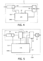
- the input signal of said transmitter station 4,6, or 8 is applied to a buffer 28.
- Said buffer 28 is coupled to a control circuit 34.
- the output of the buffer is connected to an input of a multiplexer 30.
- An output of the control circuit 34 is connected to a control input of the multiplexer 30.
- the output of the multiplexer is connected to an input of a transmitter 32, and the output of the transmitter 32 is coupled to the corresponding antenna 16, 18 or 20.
- the signal is a digital signal comprising packets of digital symbols. Said packets are temporarily stored in the buffer 22.
- the control circuit 22 determines which packets can be transmitted by the transmitter stations 4,6,8 in one frame.
- the insertion device 26 inserts a so called frame start code indicating that the first packet transmitted after the frame start code is the first packet to be transmitted in a new frame by the transmitter station. In this way it is indicated that the packets present between two subsequent frame start codes are to be transmitted in one frame.
- the packets received from the source station are temporarily stored, and the frame start codes are removed and applied to the control circuit 34.
- Said control circuit 34 controls the buffer 28 and the multiplexer 30 to construct the final transmission frame by combining the packets belonging to said frame with the packet overhead signals. Because the insertion of the frame start codes using in the source station a model of the transmission frame construction process in the transmitter station, it is ensured that the packets between two frame start codes always can be transmitted in one frame.
- the overhead signals can comprise frame synchronisation signals, clock run in signals and training signals for the receivers intended for receiving signals from the transmission network.
- the complete frame is available at the output of the multiplexer 30. Said output signal is modulated on a carrier and amplified in the transmitter 32 before it is applied to the corresponding transmitting antenna 16, 18 or 20.
- Fig. 3 graph a the signal at the input of the buffer 24 in Fig. 2 is shown. It comprises subsequent packets which are numbered 1 to 15.
- Fig. 3 graph b the signal transmitted via the transmission links is displayed. Said signal comprises the frame start codes and a plurality of time slots for transmission of the packets. The time slot number is indicated below the corresponding time slot.
- the signal transmitted via the transmission links is constructed by adding behind a frame start code the packets available in the time slots 1-19.
- the number of time slots has at least to be equal to the maximum number of packets which fit in a transmission frame. In general said number of time slots is somewhat larger to provide some stuffing capability.
- graph c the transmission frame as finally transmitted by the transmitter station is displayed. It comprises a header T which comprises all frame overhead signals, followed by the data packets.
- the frame comprises the packets to be transmitted and a number of stuffing symbols. It is observed that it is possible that the number of time slots in the signals transmitted via the transmission links is different from the number of packets transmitted in a transmission frame. It is also possible that the signals on the transmission links do not comprise stuff packets in order to reduce the required transmission capacity.
- the input symbols are applied to an input of a buffer 24.
- a first output of the buffer 24 is connected to an input of a multiplexer 26.
- a second output of the buffer 24, carrying an output signal indicating whether or not there is a complete packet available in the buffer 24, is connected to an input of a control circuit 22.
- a first output of the control circuit, carrying a read control signal, is connected to a read input of the buffer 24.
- a second output of the control circuit 22, carrying the frame start code, is connected to a second input of the multiplexer 26.
- a third output of the control circuit 22, carrying a multiplexer control signal, is connected to a control input of the multiplexer 26.
- the multiplexer 26 transforms the signal according to Fig. 3 graph a into the signal according to Fig. 3 , graph b. This is done by multiplexing the output signal of the buffer 24 with the frame start code. At the beginning of a frame the frame start code is output by the multiplexer 26. After having output the frame start code, the control circuit 22 checks whether there is a complete packet available in the buffer 24. If such a complete packet is available, the control circuit 22 issues a read signal on its read signal output, causing the buffer 24 to output said packet. In the multiplexer 26 the time slot number is added to the packet being output by the buffer 24. If no complete packet is available a so called null packet or stuff packet is transmitted.
- the frame can also contain information about the instant on which said frame was transmitted. This information can be used in the transmitter stations to calculate the transmission delay of the transmission link, in order to be able to add a predetermined delay value to obtain substantially simultaneously transmission of the digital symbols by the transmitter stations.
- the absolute timing reference can be obtained from a high precision clock, but it is also possible to obtain said absolute timing reference from the Global Positioning System ( GPS-Navstar ) by using rather cheap receivers.
- a signal received from a transmission link is applied to the buffer 28.
- the buffer 28 comprises a buffer memory 29 having its output connected to a demultiplexer 33.
- a first output of the demultiplexer 33, carrying the time slot number is connected to an input of the control circuit 34.
- a second output of the demultiplexer 33, carrying the packets to be transmitted is connected to a first input of a multiplexer 30.
- a first output of the control circuit 34 is connected to a control input of the buffer memory 29.
- a second control output of the control circuit 34 is connected to a control input of the multiplexer 33.
- a third output of the control circuit 34, carrying stuff packets, is connected to a second input of the multiplexer 30.
- a fourth output of the control circuit 34, carrying a frame overhead signal is connected to a third input of the multiplexer 30.
- a fifth output of the control circuit 34 is coupled to a control input of the multiplexer 30.
- the output of the multiplexer 30 is connected to an input of a transmitter 32.
- the output of the transmitter 32 is coupled to the corresponding antenna.
- the signals received from the transmission link is temporarily stored in the buffer memory 29.
- the frame overhead signal is selected and passed to the transmitter 32 by the multiplexer 30. After the frame overhead signal the data packets and stuff packets are transmitted.
- the control circuit 34 checks the slot number of the first packet in the buffer memory 29. If said slot number corresponds to the number of the packet to be transmitted, the packet in the buffer memory 29 is transmitted. Otherwise it means that no data packet is present in the buffer memory 29, and consequently a stuff packet is transmitted. This is repeated until the last packet in a frame is transmitted.
- the last packet of a frame is indicated by the frame start code of the subsequent frame.
- the frames assembled in this way are modulated on a carrier by the transmitter 32 and applied to the corresponding antenna for transmission.
- the above mentioned construction of the transmitter station can also be used if no stuff packets are present in the signal received from the respective transmission link.
- the decision whether or not a stuff packet should be introduced can be decided on the presence of the correct time slot number in the packet.
- this time of transmission can be used for adjusting the delay value of a delay element in order to obtain substantially simultaneously transmission by the same information by the different transmitter stations.
- an absolute time reference TIME is applied to the control circuit 34.
Landscapes
- Engineering & Computer Science (AREA)
- Signal Processing (AREA)
- Data Exchanges In Wide-Area Networks (AREA)
- Mobile Radio Communication Systems (AREA)
- Time-Division Multiplex Systems (AREA)
- Radio Transmission System (AREA)
Priority Applications (1)
| Application Number | Priority Date | Filing Date | Title |
|---|---|---|---|
| EP10012175.5A EP2271007B1 (de) | 1994-09-12 | 1995-09-06 | Gleichzeitige Übertragung in einem Gleichwellennetz |
Applications Claiming Priority (4)
| Application Number | Priority Date | Filing Date | Title |
|---|---|---|---|
| EP94202614 | 1994-09-12 | ||
| EP10012175.5A EP2271007B1 (de) | 1994-09-12 | 1995-09-06 | Gleichzeitige Übertragung in einem Gleichwellennetz |
| EP95929183A EP0728388B1 (de) | 1994-09-12 | 1995-09-06 | Übertragungsnetz, verfahren und sender zur gleichzeitigen übertragung |
| EP08151118A EP1912358A1 (de) | 1994-09-12 | 1995-09-06 | Gleichzeitige Übertragung in einem Gleichwellennetz |
Related Parent Applications (4)
| Application Number | Title | Priority Date | Filing Date |
|---|---|---|---|
| EP08151118A Division EP1912358A1 (de) | 1994-09-12 | 1995-09-06 | Gleichzeitige Übertragung in einem Gleichwellennetz |
| EP95929183A Division EP0728388B1 (de) | 1994-09-12 | 1995-09-06 | Übertragungsnetz, verfahren und sender zur gleichzeitigen übertragung |
| EP95929183.2 Division | 1996-03-21 | ||
| EP08151118.0 Division | 2008-02-06 |
Publications (2)
| Publication Number | Publication Date |
|---|---|
| EP2271007A1 true EP2271007A1 (de) | 2011-01-05 |
| EP2271007B1 EP2271007B1 (de) | 2014-05-07 |
Family
ID=8217185
Family Applications (4)
| Application Number | Title | Priority Date | Filing Date |
|---|---|---|---|
| EP10012175.5A Expired - Lifetime EP2271007B1 (de) | 1994-09-12 | 1995-09-06 | Gleichzeitige Übertragung in einem Gleichwellennetz |
| EP10012174.8A Expired - Lifetime EP2285023B1 (de) | 1994-09-12 | 1995-09-06 | Gleichzeitige Übertragung in einem Gleichwellennetz |
| EP95929183A Expired - Lifetime EP0728388B1 (de) | 1994-09-12 | 1995-09-06 | Übertragungsnetz, verfahren und sender zur gleichzeitigen übertragung |
| EP08151118A Ceased EP1912358A1 (de) | 1994-09-12 | 1995-09-06 | Gleichzeitige Übertragung in einem Gleichwellennetz |
Family Applications After (3)
| Application Number | Title | Priority Date | Filing Date |
|---|---|---|---|
| EP10012174.8A Expired - Lifetime EP2285023B1 (de) | 1994-09-12 | 1995-09-06 | Gleichzeitige Übertragung in einem Gleichwellennetz |
| EP95929183A Expired - Lifetime EP0728388B1 (de) | 1994-09-12 | 1995-09-06 | Übertragungsnetz, verfahren und sender zur gleichzeitigen übertragung |
| EP08151118A Ceased EP1912358A1 (de) | 1994-09-12 | 1995-09-06 | Gleichzeitige Übertragung in einem Gleichwellennetz |
Country Status (5)
| Country | Link |
|---|---|
| US (1) | US6011820A (de) |
| EP (4) | EP2271007B1 (de) |
| JP (2) | JP3945817B2 (de) |
| DE (1) | DE69535958D1 (de) |
| WO (1) | WO1996008889A1 (de) |
Families Citing this family (7)
| Publication number | Priority date | Publication date | Assignee | Title |
|---|---|---|---|---|
| FI101760B (fi) * | 1996-08-09 | 1998-08-14 | Nokia Telecommunications Oy | Signalointimenetelmä ja digitaalinen radiojärjestelmä |
| US7551675B2 (en) * | 2002-09-27 | 2009-06-23 | Ibiquity Digital Corporation | Method and apparatus for synchronized transmission and reception of data in a digital audio broadcasting system |
| DE10343458A1 (de) * | 2003-09-19 | 2005-05-12 | Thomson Brandt Gmbh | Verfahren zur Bearbeitung von über eine erste Schnittstelle empfangenen Datenpaketen und Vorrichtung zur Durchführung des Verfahrens |
| JP4551889B2 (ja) * | 2006-09-14 | 2010-09-29 | 株式会社東芝 | デジタル放送システムとこのシステムに用いられる放送装置及び監視装置 |
| US10117248B1 (en) * | 2016-06-29 | 2018-10-30 | Sprint Communications Company L.P. | Dynamic frequency allocation to mitigate tropospheric ducting |
| US10630395B1 (en) | 2018-12-28 | 2020-04-21 | Sprint Communications Company L.P. | Automated mitigation of atmospheric-based interference events |
| JP2023180550A (ja) * | 2022-06-09 | 2023-12-21 | 日本放送協会 | 放送システム、中継装置、及び算出装置 |
Citations (3)
| Publication number | Priority date | Publication date | Assignee | Title |
|---|---|---|---|---|
| US4972410A (en) * | 1989-07-20 | 1990-11-20 | Electrocom Automation, Inc. | Method and apparatus for controlling signal coherency in simulcast systems |
| US5216717A (en) * | 1990-03-02 | 1993-06-01 | Telediffusion De France | Frequency modulation broadcast transmitter synchronization method |
| WO1994005110A1 (en) * | 1992-08-17 | 1994-03-03 | Glenayre Electronics, Inc. | Digital simulcast transmission system |
Family Cites Families (5)
| Publication number | Priority date | Publication date | Assignee | Title |
|---|---|---|---|---|
| US5327581A (en) * | 1992-05-29 | 1994-07-05 | Motorola, Inc. | Method and apparatus for maintaining synchronization in a simulcast system |
| US5483671A (en) * | 1994-02-01 | 1996-01-09 | Motorola, Inc. | Method of determining transmission time to transmit an information packet to a remote buffer |
| DE4403408C1 (de) * | 1994-02-04 | 1995-02-23 | Grundig Emv | Verfahren zur Erkennung eines Übertragungs-Modes |
| US5586119A (en) * | 1994-08-31 | 1996-12-17 | Motorola, Inc. | Method and apparatus for packet alignment in a communication system |
| WO1999005110A1 (en) | 1997-07-25 | 1999-02-04 | Ishihara Sangyo Kaisha Ltd. | Amorphous benzoylurea and vermicides for warm-blooded animals containing the same as the active ingredient |
-
1995
- 1995-09-06 EP EP10012175.5A patent/EP2271007B1/de not_active Expired - Lifetime
- 1995-09-06 EP EP10012174.8A patent/EP2285023B1/de not_active Expired - Lifetime
- 1995-09-06 EP EP95929183A patent/EP0728388B1/de not_active Expired - Lifetime
- 1995-09-06 WO PCT/IB1995/000736 patent/WO1996008889A1/en not_active Ceased
- 1995-09-06 DE DE69535958T patent/DE69535958D1/de not_active Expired - Lifetime
- 1995-09-06 EP EP08151118A patent/EP1912358A1/de not_active Ceased
- 1995-09-06 JP JP51004096A patent/JP3945817B2/ja not_active Expired - Lifetime
-
1997
- 1997-07-19 US US08/899,492 patent/US6011820A/en not_active Expired - Lifetime
-
2006
- 2006-10-04 JP JP2006272490A patent/JP4226625B2/ja not_active Expired - Lifetime
Patent Citations (3)
| Publication number | Priority date | Publication date | Assignee | Title |
|---|---|---|---|---|
| US4972410A (en) * | 1989-07-20 | 1990-11-20 | Electrocom Automation, Inc. | Method and apparatus for controlling signal coherency in simulcast systems |
| US5216717A (en) * | 1990-03-02 | 1993-06-01 | Telediffusion De France | Frequency modulation broadcast transmitter synchronization method |
| WO1994005110A1 (en) * | 1992-08-17 | 1994-03-03 | Glenayre Electronics, Inc. | Digital simulcast transmission system |
Non-Patent Citations (2)
| Title |
|---|
| G. PLENGE: "DAB- A new sound broadcasting system, Status of the development, Routes to its introduction", EBU REVIEW TECHNICAL, no. 246, April 1991 (1991-04-01), pages 87 - 112 |
| PLENGE G: "DAB-A NEW SOUND BROADCASTING SYSTEM STATUS OF THE DEVELOPMENT - ROUTES TO ITS INTRODUCTION*", EBU REVIEW- TECHNICAL, EUROPEAN BROADCASTING UNION. BRUSSELS, BE, no. 246, 1 April 1991 (1991-04-01), pages 87 - 111, XP000219708, ISSN: 0251-0936 * |
Also Published As
| Publication number | Publication date |
|---|---|
| EP1912358A1 (de) | 2008-04-16 |
| EP2271007B1 (de) | 2014-05-07 |
| WO1996008889A1 (en) | 1996-03-21 |
| JP4226625B2 (ja) | 2009-02-18 |
| EP0728388B1 (de) | 2009-05-20 |
| US6011820A (en) | 2000-01-04 |
| DE69535958D1 (de) | 2009-07-02 |
| JPH09505965A (ja) | 1997-06-10 |
| EP0728388A1 (de) | 1996-08-28 |
| EP2285023B1 (de) | 2014-05-07 |
| JP2007060679A (ja) | 2007-03-08 |
| JP3945817B2 (ja) | 2007-07-18 |
| EP2285023A1 (de) | 2011-02-16 |
Similar Documents
| Publication | Publication Date | Title |
|---|---|---|
| US5280629A (en) | Technique for measuring channel delay | |
| EP1806865B1 (de) | Funkübertragungsverfahren und Funkübertragungsvorrichtung | |
| EP0944179A3 (de) | Funkkommunikationssystem | |
| EP0800287A3 (de) | Übertragungssystem für digitalen Tonrundfunk | |
| EP2285023B1 (de) | Gleichzeitige Übertragung in einem Gleichwellennetz | |
| KR101391398B1 (ko) | Dvb-rcs 시스템에서의 송신 방법, 수신 방법, 송신장치 및 수신 장치 | |
| US6826179B1 (en) | Packet channel implementation | |
| US6697381B1 (en) | Packet channel architecture | |
| EP0510364B1 (de) | Zwischenverstärker mit Zugriff auf die Daten des Eingangsrahmens | |
| US6731615B1 (en) | Multipoint-to-point tdma transmission system using a particular burst structure, and a corresponding transmitter | |
| WO2000064091A3 (en) | Method and system to synchronise base stations in digital telecommunication networks | |
| JPH104391A (ja) | マルチキャリア伝送方式 | |
| US6973056B2 (en) | Information transmitting and receiving method and corresponding transmitter and receiver | |
| JPH06103865B2 (ja) | 時分割多重パケツト通信方式 | |
| JPH0630069A (ja) | マルチサブキャリアによるqam伝送方式 | |
| KR101394578B1 (ko) | Eti 수신 인터페이스 장치 및 방법 | |
| JP3107152B2 (ja) | ボーレイト混合多重ページングシステム | |
| JPH0358634A (ja) | 移動通信システム | |
| JPS6231229A (ja) | 中継装置 | |
| JPS5913438A (ja) | 時分割多重無線通信方式 | |
| JPH07135578A (ja) | データ伝送システムにおける同期装置 | |
| McRae | Avalanche Communications-A Robust HF Relay Technique for Stressed Channels | |
| JPS6223239A (ja) | 通信方式 | |
| KR950022347A (ko) | 디지탈 전송장치의 서비스 채널용 클럭 선택 장치 | |
| JPH0793631B2 (ja) | ル−プ式デ−タ伝送方式 |
Legal Events
| Date | Code | Title | Description |
|---|---|---|---|
| PUAI | Public reference made under article 153(3) epc to a published international application that has entered the european phase |
Free format text: ORIGINAL CODE: 0009012 |
|
| 17P | Request for examination filed |
Effective date: 20101126 |
|
| AC | Divisional application: reference to earlier application |
Ref document number: 0728388 Country of ref document: EP Kind code of ref document: P Ref document number: 1912358 Country of ref document: EP Kind code of ref document: P |
|
| AK | Designated contracting states |
Kind code of ref document: A1 Designated state(s): DE FR GB |
|
| AX | Request for extension of the european patent |
Extension state: LT LV SI |
|
| RBV | Designated contracting states (corrected) |
Designated state(s): DE FR GB |
|
| 17Q | First examination report despatched |
Effective date: 20120221 |
|
| GRAP | Despatch of communication of intention to grant a patent |
Free format text: ORIGINAL CODE: EPIDOSNIGR1 |
|
| INTG | Intention to grant announced |
Effective date: 20131206 |
|
| GRAS | Grant fee paid |
Free format text: ORIGINAL CODE: EPIDOSNIGR3 |
|
| GRAA | (expected) grant |
Free format text: ORIGINAL CODE: 0009210 |
|
| AC | Divisional application: reference to earlier application |
Ref document number: 1912358 Country of ref document: EP Kind code of ref document: P Ref document number: 0728388 Country of ref document: EP Kind code of ref document: P |
|
| AK | Designated contracting states |
Kind code of ref document: B1 Designated state(s): DE FR GB |
|
| REG | Reference to a national code |
Ref country code: GB Ref legal event code: FG4D |
|
| REG | Reference to a national code |
Ref country code: DE Ref legal event code: R096 Ref document number: 69536311 Country of ref document: DE Effective date: 20140612 |
|
| PGFP | Annual fee paid to national office [announced via postgrant information from national office to epo] |
Ref country code: DE Payment date: 20140922 Year of fee payment: 20 |
|
| PGFP | Annual fee paid to national office [announced via postgrant information from national office to epo] |
Ref country code: FR Payment date: 20140919 Year of fee payment: 20 Ref country code: GB Payment date: 20140919 Year of fee payment: 20 |
|
| REG | Reference to a national code |
Ref country code: DE Ref legal event code: R097 Ref document number: 69536311 Country of ref document: DE |
|
| PLBE | No opposition filed within time limit |
Free format text: ORIGINAL CODE: 0009261 |
|
| STAA | Information on the status of an ep patent application or granted ep patent |
Free format text: STATUS: NO OPPOSITION FILED WITHIN TIME LIMIT |
|
| 26N | No opposition filed |
Effective date: 20150210 |
|
| REG | Reference to a national code |
Ref country code: DE Ref legal event code: R097 Ref document number: 69536311 Country of ref document: DE Effective date: 20150210 |
|
| REG | Reference to a national code |
Ref country code: DE Ref legal event code: R071 Ref document number: 69536311 Country of ref document: DE |
|
| REG | Reference to a national code |
Ref country code: GB Ref legal event code: PE20 Expiry date: 20150905 |
|
| PG25 | Lapsed in a contracting state [announced via postgrant information from national office to epo] |
Ref country code: GB Free format text: LAPSE BECAUSE OF EXPIRATION OF PROTECTION Effective date: 20150905 |