EP2270316A2 - System for aligning turbine components - Google Patents
System for aligning turbine components Download PDFInfo
- Publication number
- EP2270316A2 EP2270316A2 EP10167145A EP10167145A EP2270316A2 EP 2270316 A2 EP2270316 A2 EP 2270316A2 EP 10167145 A EP10167145 A EP 10167145A EP 10167145 A EP10167145 A EP 10167145A EP 2270316 A2 EP2270316 A2 EP 2270316A2
- Authority
- EP
- European Patent Office
- Prior art keywords
- key
- turbine
- support
- segments
- thickness
- Prior art date
- Legal status (The legal status is an assumption and is not a legal conclusion. Google has not performed a legal analysis and makes no representation as to the accuracy of the status listed.)
- Withdrawn
Links
Images


Classifications
-
- F—MECHANICAL ENGINEERING; LIGHTING; HEATING; WEAPONS; BLASTING
- F01—MACHINES OR ENGINES IN GENERAL; ENGINE PLANTS IN GENERAL; STEAM ENGINES
- F01D—NON-POSITIVE DISPLACEMENT MACHINES OR ENGINES, e.g. STEAM TURBINES
- F01D25/00—Component parts, details, or accessories, not provided for in, or of interest apart from, other groups
- F01D25/28—Supporting or mounting arrangements, e.g. for turbine casing
-
- F—MECHANICAL ENGINEERING; LIGHTING; HEATING; WEAPONS; BLASTING
- F05—INDEXING SCHEMES RELATING TO ENGINES OR PUMPS IN VARIOUS SUBCLASSES OF CLASSES F01-F04
- F05D—INDEXING SCHEME FOR ASPECTS RELATING TO NON-POSITIVE-DISPLACEMENT MACHINES OR ENGINES, GAS-TURBINES OR JET-PROPULSION PLANTS
- F05D2230/00—Manufacture
- F05D2230/60—Assembly methods
- F05D2230/64—Assembly methods using positioning or alignment devices for aligning or centring, e.g. pins
-
- F—MECHANICAL ENGINEERING; LIGHTING; HEATING; WEAPONS; BLASTING
- F05—INDEXING SCHEMES RELATING TO ENGINES OR PUMPS IN VARIOUS SUBCLASSES OF CLASSES F01-F04
- F05D—INDEXING SCHEME FOR ASPECTS RELATING TO NON-POSITIVE-DISPLACEMENT MACHINES OR ENGINES, GAS-TURBINES OR JET-PROPULSION PLANTS
- F05D2240/00—Components
- F05D2240/40—Use of a multiplicity of similar components
Definitions
- the subject matter disclosed herein relates to turbine engines and, more specifically, to assembly, support, and alignment of components of the turbine engines.
- steam turbines may include various sections designed to be assembled during installation. Each steam turbine may be covered by a turbine shell and may be separated from other turbines by a "standard" (also referred to as a "pedestal) to provide a housing for supporting components.
- the turbine shells may include arms or other extensions that may be supported by the standard, such as through a vertical support on the standard itself.
- the turbine shell generally covers and protects the rotary components of the turbine. During installation, the turbine shell is generally aligned with rotary components to avoid interference with the components.
- the vertical supports on the standard may include extra stock on its thickness to support the turbine shell. To install and properly align the turbine shell, the extra stock on the supports may be machined (e.g., grinded) down in the field to achieve the desired alignment of the turbine shell and rotary component. However, the machining operation may delay initial startup of the steam turbine depending on the availability of the shop. Further, some plants or install sites may not have any access to a machine shop to perform the machining of the vertical support.
- a system in a first embodiment, includes a turbine engine and a support assembly configured to support the turbine engine.
- the support assembly comprises a first support and a second support.
- the system further includes a key pack configured to mount between the first and second supports, wherein the key pack includes a plurality of key segments selectively arranged one over another to define a thickness.
- a system in a second embodiment, includes a turbine support key, comprising a set of key segments selectively stackable together in a plurality of combinations to adjust a thickness between turbine supports based solely on a selection of the key segments from the set.
- a method in a third embodiment, includes defining a thickness solely by selectively stacking two or more key segments from a key pack into a key stack and aligning a turbine shell with internal rotary components via placement of the key stack between first and second supports.
- Embodiments of the present invention include a key pack having selectively addable or removable segments for aligning turbine components, e.g., turbine shells, of a steam turbine.
- the key pack may include a plurality of plates of equal or different thicknesses.
- the key pack is designed to enable alignment of the turbine components without machining.
- one or more segments e.g., plates
- the key pack may include a main key and segments that may be selectively stacked (e.g., added or removed) to define a thickness on a support block of a standard.
- the support block may support an arm of an upper half turbine shell, such that the thickness generally aligns the turbine shell with the internal rotary components of the turbine.
- the main key may include a slot configured to engage a lockable plate on the support block to secure the key pack. As appreciated, the key pack enables quick and easy alignment of turbine components in the field without the need for machining.
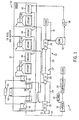
- FIG. 1 is a schematic flow diagram of an embodiment of a combined cycle power generation system 10 having a gas turbine 12, a steam turbine 22, and a heat recovery steam generation (HRSG) system 32.
- System 10 may employ one or more key packs to align various components in the gas turbine 12, the steam turbine 22, and/or the HRSG 12.
- Each installed key pack may include one or more key segments (e.g., plates) selected from a plurality of segments in an installation kit having the uninstalled key pack. During setup, some but not necessarily all of the key segments may be used to align components at a suitable dimension defined by thickness of the key segments.
- the system 10 may include the gas turbine 12 for driving a first load 14.
- the first load 14 may, for instance, be an electrical generator for producing electrical power.
- the gas turbine 12 may include a turbine 16, a combustor or combustion chamber 18, and a compressor 20.
- the system 10 may also include the steam turbine 22 for driving a second load 24.
- the second load 24 may also be an electrical generator for generating electrical power.
- both the first and second loads 14, 24 may be other types of loads capable of being driven by the gas turbine 12 and steam turbine 22.
- the gas turbine 12 and steam turbine 22 may drive separate loads 14 and 24, as shown in the illustrated embodiment, the gas turbine 12 and steam turbine 22 may also be utilized in tandem to drive a single load via a single shaft.
- the steam turbine 22 may include one low-pressure section 26 (LP ST), one intermediate-pressure section 28 (IP ST), and one high-pressure section 30 (HP ST).
- LP ST low-pressure section 26
- IP ST intermediate-pressure section 28
- HP ST high-pressure section 30
- the specific configuration of the steam turbine 22, as well as the gas turbine 12 may be implementation-specific and may include any combination of sections.
- Each section of the steam turbine 22, e.g., the low pressure section 26, the intermediate pressure section 28, and the high-pressure section 30, may be generally supported and separated by mid standards 29 (e.g., pedestals).
- end standards 31 e.g., pedestals
- the standards 29 and 31 may be disposed along the axis of the turbine 22, and may include various components such as supports, pickups, and piping between the turbine sections 26, 28, and 30.
- the standards 29 and 31 may also provide for alignment of the turbine shells of the sections 26, 28, and 30, though selection of segments in a key pack.
- the system 10 may also include the multi-stage HRSG 32.
- the components of the HRSG 32 in the illustrated embodiment are a simplified depiction of the HRSG 32 and are not intended to be limiting. Rather, the illustrated HRSG 32 is shown to convey the general operation of such HRSG systems.
- Heated exhaust gas 34 from the gas turbine 12 may be transported into the HRSG 32 and used to heat steam used to power the steam turbine 22.
- Exhaust from the low-pressure section 26 of the steam turbine 22 may be directed into a condenser 36.
- Condensate from the condenser 36 may, in turn, be directed into a low-pressure section of the HRSG 32 with the aid of a condensate pump 38.
- the condensate may then flow through a low-pressure economizer 40 (LPECON), a device configured to heat feedwater with gases, which may be used to heat the condensate.
- LPECON low-pressure economizer 40
- LPEVAP low-pressure evaporator 42
- IPECON intermediate-pressure economizer 44
- a portion of the condensate may be directed into an intermediate-pressure evaporator 46 (IPEVAP) while the rest may be pumped toward a high-pressure economizer 48 (HPECON).
- IPEVAP intermediate-pressure evaporator
- HPECON high-pressure economizer 48
- Steam from the intermediate-pressure evaporator 46 may be sent to the intermediate-pressure section 28 of the steam turbine 22.
- the connections between the economizers, evaporators, and the steam turbine 22 may vary across implementations as the illustrated embodiment is merely illustrative of the general operation of an HRSG system that may employ unique aspects of the present embodiments.
- condensate from the high-pressure economizer 48 may be directed into a high-pressure evaporator 50 (HPEVAP).
- HPEVAP high-pressure evaporator 50
- Steam exiting the high-pressure evaporator 50 may be directed into a primary high-pressure superheater 52 and a finishing high-pressure superheater 54, where the steam is superheated and eventually sent to the high-pressure section 30 of the steam turbine 22.
- Exhaust from the high-pressure section 30 of the steam turbine 22 may, in turn, be directed into the intermediate-pressure section 28 of the steam turbine 22.
- Exhaust from the intermediate-pressure section 28 of the steam turbine 22 may be directed into the low-pressure section 26 of the steam turbine 22.
- An inter-stage attemperator 56 may be located in between the primary high-pressure superheater 52 and the finishing high-pressure superheater 54.
- the inter-stage attemperator 56 may allow for more robust control of the exhaust temperature of steam from the finishing high-pressure superheater 54.
- the inter-stage attemperator 56 may be configured to control the temperature of steam exiting the finishing high-pressure superheater 54 by injecting cooler feedwater spray into the superheated steam upstream of the finishing high-pressure superheater 54 whenever the exhaust temperature of the steam exiting the finishing high-pressure superheater 54 exceeds a predetermined value.
- exhaust from the high-pressure section 30 of the steam turbine 22 may be directed into a primary re-heater 58 and a secondary re-heater 60 where it may be reheated before being directed into the intermediate-pressure section 28 of the steam turbine 22.
- the primary re-heater 58 and secondary re-heater 60 may also be associated with an inter-stage attemperator 62 for controlling the exhaust steam temperature from the re-heaters.
- the inter-stage attemperator 62 may be configured to control the temperature of steam exiting the secondary re-heater 60 by injecting cooler feedwater spray into the superheated steam upstream of the secondary re-heater 60 whenever the exhaust temperature of the steam exiting the secondary re-heater 60 exceeds a predetermined value.
- hot exhaust gas 34 may flow from the gas turbine 12 and pass through the HRSG 32 and may be used to generate high-pressure, high-temperature steam.
- the steam produced by the HRSG 32 may then be passed through the steam turbine 22 for power generation.
- the produced steam may also be supplied to any other processes where superheated steam may be used.
- the gas turbine 12 cycle is often referred to as the "topping cycle”
- the steam turbine 22 generation cycle is often referred to as the "bottoming cycle.”
- FIG. 2 is a perspective view of a turbine standard 70, e.g., a mid standard 29 or end standard 31, supporting a turbine shell 72, e.g., a shell of the low pressure section 26, the intermediate pressure section 28, and the high-pressure section 30.
- the standard 70 may include an upper half 74 and a lower half 76
- the turbine shell 72 may include an upper half turbine shell 78 or a lower half turbine shell 80.
- the upper half turbine shell 78 may be generally supported and aligned by shell arm support block 82 of the standard 70.
- a key pack 84 (also referred to as a “turbine support key” or a “key and shim assembly”) may be disposed on the support 82 to provide for adjustment of the height of the support block 82 and alignment of the upper half turbine shell 78. As will be appreciated, the alignment of the upper half turbine shell 78 also aligns the lower half turbine shell 80, as the two shell halves 78 and 80 are bolted together along their common joint surfaces.
- the key pack 84 may include one or more key segments (e.g., plates or shims) selectively stacked to define a suitable thickness for alignment. As appreciated, the key pack 84 may include key segments of equal and/or different heights, such that the suitable thickness can be achieved without any machining, thereby substantially simplifying the installation process.
- FIG. 3 is a close-up perspective view of region 3-3 of FIG. 2 , depicting the support 82 and key pack 84 in accordance with an embodiment of the present invention.
- the upper half turbine shell 78 may include arms 86 extending parallel to the axis of the turbine shell 72 and supported on the support block 82 via the key pack 84.
- the support block 82 may include a lower lock plate 88 that may secure and lock the key pack 84 to the support block 82.
- FIG. 4 depicts an exploded perspective view of the upper half turbine shell 78, the lower half turbine shell 80, and the key pack 84 in accordance with an embodiment of the present invention.
- rotary components e.g., shaft, wheels, turbine blades, etc.
- This cavity supports other stationary turbine components, e.g., diaphragms, seals and steam packing, which typically have close radial clearances with rotary components.
- the upper half turbine shell 78 and the lower half turbine shell 80 which are bolted together, may be aligned relative to the turbine rotary components along the vertical axis indicated by arrow 92.
- the lower half turbine shell 80 may include cast shell extensions 94 along the joint close to the support 82. These extensions 94 may be secured to the standard 70 via a pin and bolt assembly 96 or any suitable fasteners, to prevent vertical lifting of the upper shell arm relative to support block 82 during turbine operation.
- the key pack 84 is exploded into a plurality of segments.
- the key pack 84 may include a main key segment 98 (e.g., a main key) and one or more segments 100 (e.g., shims).
- one or more segments 100 may be selectively added to or removed from the key pack 84 to adjust the height of the support block 82 and alignment of the upper half turbine shell 78 and lower half shell 80 relative to the turbine rotary components.
- These key segments 98 and 100 may have equal or different thickness from one another.
- the key pack 84 may include at least greater than approximately 5, 10, 15, 20, 25, 30, 35, 40, 45, 50, or more segments for selective use during assembly.
- the key pack 84 may include segments that increase in thickness by at least approximately 5, 10, 15, 20, 25, 30, 35, 40, 45, 50, or more percent.
- FIG. 5 depicts a close up perspective view of the support block 82 with the key pack 84 installed in accordance with an embodiment of the present invention.
- FIG. 6 depicts the close-up perspective view of FIG. 5 with segments of the key pack 84 exploded from one another in accordance with an embodiment of the present invention.
- the key pack 84 may be retained by side tabs, bars, or protrusions 101 surrounding a recess 102 of the support block 82.
- the recess 102 may have a shape and dimensions generally similarly to the segments 100 and main key 98 to retain the key pack 84.
- the support block 82 may also include a lower lock plate 88 that engages the main key 98 to secure the key pack 84.
- the lower lock plate 88 may be secured to the support block 82 by one or more bolts 104 or any suitable fasteners.
- the lower lock plate 88 may include a protrusion 103 and/or recessed edge 104 configured to engage a protrusion 105 and/or recess 106 of the main key 98.
- the key pack 84 when assembled into the recess 102 of the support block 82, the key pack 84 may be retained from moving in the direction indicated by arrow 108 by the lower lock plate 88 and direction indicated by arrow 110 by the recess 102.
- the weight of the arm 86 may provide sufficient force on the key pack 84 to aid in blocking movement in the directions indicated by arrow 92, arrow 108 and arrow 110.
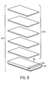
- FIGS. 7 and 8 depict top and bottom exploded perspective view of the key pack 84 in accordance with an embodiment of present invention.
- FIG. 7 depicts a top exploded perspective view of the exploded key pack 84 in the desired vertical orientation
- FIG. 8 depicts a bottom exploded perspective view of the exploded key pack 84 in the opposite vertical orientation.
- the key pack 84 may include one or more segments 100 (e.g., shims) disposed vertically under the main key segment 98 (e.g., main key).
- a thickness of the key pack 84 is variable based on the selection of the segments.
- an installation kit may include the key pack 84 with an excessive number and variety of segments (e.g., main key 98 and segments 100) to enable an installer to achieve the desired thickness quickly and easily without any machining.
- the thickness of the key pack 84 via selection of key segments, the alignment of the upper half turbine shell 78 and lower turbine shell 80 relative to the turbine rotary components may be adjusted without machining.
- the main key 98 may define a minimum thickness of the key pack 84, and the segments 100 may be selectively used (or not used) to attain the desired thickness.
- the segments 100 may each have a thickness of at least less than approximately 5, 10, 15, 20, 25, 30, 35, 40, 45, 50 percent of the main key 98, or any combination thereof.
- the segments 100 may have a thickness of between approximately 0.5 percent and 3 percent of the main key 98.
- the segments 100 may each have the same thickness or have different thicknesses from one another.
- the main key 98 may be less than or equal to approximately 0.5, 1, 1.5, 2, 2.5, or 3 inch thick, and the segments may be less than or equal to approximately 5, 10, 15, 20, 25, 30, 35, 40, 45, 50, 100, 200, 300, or 500 mils thick.
- the main key 98 may be approximately 0.5 to 1.5 inch thick and the segments 100 may be approximately 0 to 500, 5 to 300, or 10 to 100 mils thick.
- the number and dimensions of the main key 98 and segments 100 may vary by application.
- the key pack 84 defines a thickness of the support block 82 solely without any machining.
- neither the arm 86 of the upper half turbine shell 78 nor the support block 82 is machined or otherwise physically altered to achieve the desired thickness.
- the thickness of the support assembly is solely defmed by the selection of the segments 100 included in the key pack 84.
- use of the key pack 84 may enable faster assembly and startup of a turbine 22 and corresponding power generation system 10.
- the main key 98 may consist essentially of stellite, steel, or other suitable material capable of supporting the weight of the upper half turbine shell 78. In one embodiment, the main key 98 may be capable of supporting a weight of at least greater than approximately 50,000 pounds.
- FIG. 9 depicts a key pack 114 having protruding frame 115 disposed about a key pocket 116 in accordance with an alternate embodiment of the present invention.
- a main key segment 118 e.g., main key
- the pocket 116 may have the same general size and dimensions (width and length) as the segments 120.
- the pocket 116 also may have any depth suitable for aiding retention of the segments 120.
- the key pocket 116 may also include a protrusion 117 and/or a slot 119 to retain the key pack 114 to the support block 82, as discussed above.
- a "base" segment 122 (e.g., base shim) may also be included in the key pack 114.
- the base segment 122 may be made from the same material as the key 118 and may be placed on the bottom of the key pack 114 to provide additional spacing for the key pocket 116.
- the key 118 and the base segment 122 may be formed from stellite, steel, or other suitable materials.
- the key pack 114 maybe used in a similar manner as the embodiments described above to define a thickness for the support block 82.
- FIG. 10 is a flowchart depicting a process 130 for defining a thickness by selectively stacking one or more segments 100 (e.g., shims) in the key pack 84 in accordance with an embodiment of the present invention.
- segments 100 e.g., shims
- FIG. 10 is a flowchart depicting a process 130 for defining a thickness by selectively stacking one or more segments 100 (e.g., shims) in the key pack 84 in accordance with an embodiment of the present invention.
- the appropriate alignment of the upper half turbine shell 78 and the lower half turbine shell 80 relative to the turbine rotary components may be determined (block 132), such as by determining an appropriate thickness between the arm 86 of the upper half turbine shell 78 and the support block 82, as discussed above.
- Such alignment may define the cavity 90 for enclosure of the rotary components of the turbine 22.
- segments 100 may be selectively added or removed (i.e., stacked) to the key pack 84, in combination with main key 98, to define a thickness between the support block 82 and the arm 86 (block 134).
- the selection may be an iterative process, such that each modification of the key pack 84 results in a new determination of alignment (and thickness) (block 132).
- the upper half turbine shell 78 may be installed and bolted to the lower half turbine shell 80 (block 136).
- the thickness defined by the key pack 84 between the arm 86 and the upper half turbine shell 78 aligns the turbine shell halves 78 and 80 with the turbine rotary components.
- the key pack 84 enables quick and easy alignment without any machining during installation.
- the alignment (and thickness) may be redetermined (block 132)
Landscapes
- Engineering & Computer Science (AREA)
- Mechanical Engineering (AREA)
- General Engineering & Computer Science (AREA)
- Turbine Rotor Nozzle Sealing (AREA)
- Support Of The Bearing (AREA)
Abstract
Description
- The subject matter disclosed herein relates to turbine engines and, more specifically, to assembly, support, and alignment of components of the turbine engines.
- In certain applications, steam turbines may include various sections designed to be assembled during installation. Each steam turbine may be covered by a turbine shell and may be separated from other turbines by a "standard" (also referred to as a "pedestal) to provide a housing for supporting components. The turbine shells may include arms or other extensions that may be supported by the standard, such as through a vertical support on the standard itself.
- The turbine shell generally covers and protects the rotary components of the turbine. During installation, the turbine shell is generally aligned with rotary components to avoid interference with the components. The vertical supports on the standard may include extra stock on its thickness to support the turbine shell. To install and properly align the turbine shell, the extra stock on the supports may be machined (e.g., grinded) down in the field to achieve the desired alignment of the turbine shell and rotary component. However, the machining operation may delay initial startup of the steam turbine depending on the availability of the shop. Further, some plants or install sites may not have any access to a machine shop to perform the machining of the vertical support.
- Certain embodiments commensurate in scope with the originally claimed invention are summarized below. These embodiments are not intended to limit the scope of the claimed invention, but rather these embodiments are intended only to provide a brief summary of possible forms of the invention. Indeed, the invention may encompass a variety of forms that may be similar to or different from the embodiments set forth below.
- In a first embodiment, a system includes a turbine engine and a support assembly configured to support the turbine engine. The support assembly comprises a first support and a second support. The system further includes a key pack configured to mount between the first and second supports, wherein the key pack includes a plurality of key segments selectively arranged one over another to define a thickness.
- In a second embodiment, a system includes a turbine support key, comprising a set of key segments selectively stackable together in a plurality of combinations to adjust a thickness between turbine supports based solely on a selection of the key segments from the set.
- In a third embodiment, a method includes defining a thickness solely by selectively stacking two or more key segments from a key pack into a key stack and aligning a turbine shell with internal rotary components via placement of the key stack between first and second supports.
- There follows a detailed description of embodiments of the invention by way of example only with reference to the accompanying drawings, in which:
-
FIG. 1 is a schematic flow diagram of an embodiment of a combined cycle power generation system having a gas turbine, a steam turbine, and a heat recovery steam generation (HRSG) system; -
FIG. 2 is a perspective view of a turbine standard and a turbine shell in accordance with an embodiment of the present invention; -
FIG. 3 is a close-up view of region 3-3 ofFIG. 2 depicting a support and key pack in accordance with an embodiment of the present invention; -
FIG. 4 is an exploded perspective view of the turbine shell ofFIG. 2 and a key pack in accordance with an embodiment of the present invention; -
FIG. 5 is a close-up perspective view of a support block and a key pack ofFIGS. 2-4 in accordance with an embodiment of the present invention; -
FIG. 6 is a close-up exploded perspective view of the support block and the key pack ofFIG. 5 in accordance with an embodiment of the present invention; -
FIGS. 7 and8 depict close-up exploded views of the key pack ofFIGS. 2-6 in accordance with an embodiment of the present invention; -
FIG. 9 depicts a close-up exploded view of a key pack having a key pocket in accordance with another embodiment of the present invention; and -
FIG. 10 depicts a process for defining a thickness by selectively stacking one or more segments in a key pack in accordance with an embodiment of the present invention. - One or more specific embodiments of the present invention will be described below. In an effort to provide a concise description of these embodiments, all features of an actual implementation may not be described in the specification. It should be appreciated that in the development of any such actual implementation, as in any engineering or design project, numerous implementation-specific decisions must be made to achieve the developers' specific goals, such as compliance with system-related and business-related constraints, which may vary from one implementation to another. Moreover, it should be appreciated that such a development effort might be complex and time consuming, but would nevertheless be a routine undertaking of design, fabrication, and manufacture for those of ordinary skill having the benefit of this disclosure.
- When introducing elements of various embodiments of the present invention, the articles "a," "an," "the," and "said" are intended to mean that there are one or more of the elements. The terms "comprising," "including," and "having" are intended to be inclusive and mean that there may be additional elements other than the listed elements.
- Embodiments of the present invention include a key pack having selectively addable or removable segments for aligning turbine components, e.g., turbine shells, of a steam turbine. The key pack may include a plurality of plates of equal or different thicknesses. The key pack is designed to enable alignment of the turbine components without machining. For example, one or more segments (e.g., plates) may be used as needed to define an appropriate thickness for alignment, while the extra segments are not used. In one embodiment, the key pack may include a main key and segments that may be selectively stacked (e.g., added or removed) to define a thickness on a support block of a standard. The support block may support an arm of an upper half turbine shell, such that the thickness generally aligns the turbine shell with the internal rotary components of the turbine. The main key may include a slot configured to engage a lockable plate on the support block to secure the key pack. As appreciated, the key pack enables quick and easy alignment of turbine components in the field without the need for machining.
-
FIG. 1 is a schematic flow diagram of an embodiment of a combined cyclepower generation system 10 having agas turbine 12, asteam turbine 22, and a heat recovery steam generation (HRSG)system 32.System 10 may employ one or more key packs to align various components in thegas turbine 12, thesteam turbine 22, and/or the HRSG 12. Each installed key pack may include one or more key segments (e.g., plates) selected from a plurality of segments in an installation kit having the uninstalled key pack. During setup, some but not necessarily all of the key segments may be used to align components at a suitable dimension defined by thickness of the key segments. - The
system 10 may include thegas turbine 12 for driving a first load 14. The first load 14 may, for instance, be an electrical generator for producing electrical power. Thegas turbine 12 may include aturbine 16, a combustor orcombustion chamber 18, and acompressor 20. Thesystem 10 may also include thesteam turbine 22 for driving a second load 24. The second load 24 may also be an electrical generator for generating electrical power. However, both the first and second loads 14, 24 may be other types of loads capable of being driven by thegas turbine 12 andsteam turbine 22. In addition, although thegas turbine 12 andsteam turbine 22 may drive separate loads 14 and 24, as shown in the illustrated embodiment, thegas turbine 12 andsteam turbine 22 may also be utilized in tandem to drive a single load via a single shaft. In the illustrated embodiment, thesteam turbine 22 may include one low-pressure section 26 (LP ST), one intermediate-pressure section 28 (IP ST), and one high-pressure section 30 (HP ST). However, the specific configuration of thesteam turbine 22, as well as thegas turbine 12, may be implementation-specific and may include any combination of sections. - Each section of the
steam turbine 22, e.g., thelow pressure section 26, theintermediate pressure section 28, and the high-pressure section 30, may be generally supported and separated by mid standards 29 (e.g., pedestals). Similarly, end standards 31 (e.g., pedestals) may be generally support the ends of thehigh pressure section 30 and thelow pressure section 26. Thestandards turbine 22, and may include various components such as supports, pickups, and piping between theturbine sections standards sections - The
system 10 may also include the multi-stage HRSG 32. The components of theHRSG 32 in the illustrated embodiment are a simplified depiction of theHRSG 32 and are not intended to be limiting. Rather, the illustratedHRSG 32 is shown to convey the general operation of such HRSG systems.Heated exhaust gas 34 from thegas turbine 12 may be transported into theHRSG 32 and used to heat steam used to power thesteam turbine 22. Exhaust from the low-pressure section 26 of thesteam turbine 22 may be directed into acondenser 36. Condensate from thecondenser 36 may, in turn, be directed into a low-pressure section of theHRSG 32 with the aid of acondensate pump 38. - The condensate may then flow through a low-pressure economizer 40 (LPECON), a device configured to heat feedwater with gases, which may be used to heat the condensate. From the low-
pressure economizer 40, a portion of the condensate may be directed into a low-pressure evaporator 42 (LPEVAP) while the rest may be pumped toward an intermediate-pressure economizer 44 (IPECON). Steam from the low-pressure evaporator 42 may be returned to the low-pressure section 26 of thesteam turbine 22. Likewise, from the intermediate-pressure economizer 44, a portion of the condensate may be directed into an intermediate-pressure evaporator 46 (IPEVAP) while the rest may be pumped toward a high-pressure economizer 48 (HPECON). Steam from the intermediate-pressure evaporator 46 may be sent to the intermediate-pressure section 28 of thesteam turbine 22. Again, the connections between the economizers, evaporators, and thesteam turbine 22 may vary across implementations as the illustrated embodiment is merely illustrative of the general operation of an HRSG system that may employ unique aspects of the present embodiments. - Finally, condensate from the high-
pressure economizer 48 may be directed into a high-pressure evaporator 50 (HPEVAP). Steam exiting the high-pressure evaporator 50 may be directed into a primary high-pressure superheater 52 and a finishing high-pressure superheater 54, where the steam is superheated and eventually sent to the high-pressure section 30 of thesteam turbine 22. Exhaust from the high-pressure section 30 of thesteam turbine 22 may, in turn, be directed into the intermediate-pressure section 28 of thesteam turbine 22. Exhaust from the intermediate-pressure section 28 of thesteam turbine 22 may be directed into the low-pressure section 26 of thesteam turbine 22. - An
inter-stage attemperator 56 may be located in between the primary high-pressure superheater 52 and the finishing high-pressure superheater 54. Theinter-stage attemperator 56 may allow for more robust control of the exhaust temperature of steam from the finishing high-pressure superheater 54. Specifically, theinter-stage attemperator 56 may be configured to control the temperature of steam exiting the finishing high-pressure superheater 54 by injecting cooler feedwater spray into the superheated steam upstream of the finishing high-pressure superheater 54 whenever the exhaust temperature of the steam exiting the finishing high-pressure superheater 54 exceeds a predetermined value. - In addition, exhaust from the high-
pressure section 30 of thesteam turbine 22 may be directed into aprimary re-heater 58 and asecondary re-heater 60 where it may be reheated before being directed into the intermediate-pressure section 28 of thesteam turbine 22. Theprimary re-heater 58 andsecondary re-heater 60 may also be associated with aninter-stage attemperator 62 for controlling the exhaust steam temperature from the re-heaters. Specifically, theinter-stage attemperator 62 may be configured to control the temperature of steam exiting thesecondary re-heater 60 by injecting cooler feedwater spray into the superheated steam upstream of thesecondary re-heater 60 whenever the exhaust temperature of the steam exiting thesecondary re-heater 60 exceeds a predetermined value. - In combined cycle systems such as
system 10,hot exhaust gas 34 may flow from thegas turbine 12 and pass through theHRSG 32 and may be used to generate high-pressure, high-temperature steam. The steam produced by theHRSG 32 may then be passed through thesteam turbine 22 for power generation. In addition, the produced steam may also be supplied to any other processes where superheated steam may be used. Thegas turbine 12 cycle is often referred to as the "topping cycle," whereas thesteam turbine 22 generation cycle is often referred to as the "bottoming cycle." By combining these two cycles as illustrated inFIG. 1 , the combined cyclepower generation system 10 may lead to greater efficiencies in both cycles. In particular, exhaust heat from the topping cycle may be captured and used to generate steam for use in the bottoming cycle. -
FIG. 2 is a perspective view of aturbine standard 70, e.g., a mid standard 29 orend standard 31, supporting aturbine shell 72, e.g., a shell of thelow pressure section 26, theintermediate pressure section 28, and the high-pressure section 30. The standard 70 may include anupper half 74 and alower half 76, and theturbine shell 72 may include an upperhalf turbine shell 78 or a lowerhalf turbine shell 80. The upperhalf turbine shell 78 may be generally supported and aligned by shellarm support block 82 of the standard 70. As described in detail below, a key pack 84 (also referred to as a "turbine support key" or a "key and shim assembly") may be disposed on thesupport 82 to provide for adjustment of the height of thesupport block 82 and alignment of the upperhalf turbine shell 78. As will be appreciated, the alignment of the upperhalf turbine shell 78 also aligns the lowerhalf turbine shell 80, as the twoshell halves key pack 84 may include one or more key segments (e.g., plates or shims) selectively stacked to define a suitable thickness for alignment. As appreciated, thekey pack 84 may include key segments of equal and/or different heights, such that the suitable thickness can be achieved without any machining, thereby substantially simplifying the installation process. -
FIG. 3 is a close-up perspective view of region 3-3 ofFIG. 2 , depicting thesupport 82 andkey pack 84 in accordance with an embodiment of the present invention. As shown inFIG. 3 , the upperhalf turbine shell 78 may includearms 86 extending parallel to the axis of theturbine shell 72 and supported on thesupport block 82 via thekey pack 84. Thesupport block 82 may include alower lock plate 88 that may secure and lock thekey pack 84 to thesupport block 82. -
FIG. 4 depicts an exploded perspective view of the upperhalf turbine shell 78, the lowerhalf turbine shell 80, and thekey pack 84 in accordance with an embodiment of the present invention. When assembled, rotary components (e.g., shaft, wheels, turbine blades, etc.) of theturbine 22 may be disposed in aninternal cavity 90 generally defined by the upperhalf turbine shell 78 and the lowerhalf turbine shell 80 of theturbine 72. This cavity supports other stationary turbine components, e.g., diaphragms, seals and steam packing, which typically have close radial clearances with rotary components. Thus, to provide the desired radial running clearance for the rotary components, the upperhalf turbine shell 78 and the lowerhalf turbine shell 80, which are bolted together, may be aligned relative to the turbine rotary components along the vertical axis indicated byarrow 92. As seen inFIGS. 3 and4 , the lowerhalf turbine shell 80 may include castshell extensions 94 along the joint close to thesupport 82. Theseextensions 94 may be secured to the standard 70 via a pin and boltassembly 96 or any suitable fasteners, to prevent vertical lifting of the upper shell arm relative to supportblock 82 during turbine operation. - As illustrated in
FIG. 4 , thekey pack 84 is exploded into a plurality of segments. Thekey pack 84 may include a main key segment 98 (e.g., a main key) and one or more segments 100 (e.g., shims). As explained further below, one ormore segments 100 may be selectively added to or removed from thekey pack 84 to adjust the height of thesupport block 82 and alignment of the upperhalf turbine shell 78 andlower half shell 80 relative to the turbine rotary components. Thesekey segments key pack 84 may include at least greater than approximately 5, 10, 15, 20, 25, 30, 35, 40, 45, 50, or more segments for selective use during assembly. Thekey pack 84 may include segments that increase in thickness by at least approximately 5, 10, 15, 20, 25, 30, 35, 40, 45, 50, or more percent. -
FIG. 5 depicts a close up perspective view of thesupport block 82 with thekey pack 84 installed in accordance with an embodiment of the present invention. Similarly,FIG. 6 depicts the close-up perspective view ofFIG. 5 with segments of thekey pack 84 exploded from one another in accordance with an embodiment of the present invention. As seen inFIGS. 5 and6 , thekey pack 84 may be retained by side tabs, bars, orprotrusions 101 surrounding arecess 102 of thesupport block 82. Therecess 102 may have a shape and dimensions generally similarly to thesegments 100 and main key 98 to retain thekey pack 84. - As mentioned above, the
support block 82 may also include alower lock plate 88 that engages the main key 98 to secure thekey pack 84. Thelower lock plate 88 may be secured to thesupport block 82 by one ormore bolts 104 or any suitable fasteners. Thelower lock plate 88 may include aprotrusion 103 and/or recessededge 104 configured to engage aprotrusion 105 and/orrecess 106 of themain key 98. Thus, when assembled into therecess 102 of thesupport block 82, thekey pack 84 may be retained from moving in the direction indicated byarrow 108 by thelower lock plate 88 and direction indicated byarrow 110 by therecess 102. The weight of thearm 86 may provide sufficient force on thekey pack 84 to aid in blocking movement in the directions indicated byarrow 92,arrow 108 andarrow 110. -
FIGS. 7 and8 depict top and bottom exploded perspective view of thekey pack 84 in accordance with an embodiment of present invention.FIG. 7 depicts a top exploded perspective view of the explodedkey pack 84 in the desired vertical orientation, andFIG. 8 depicts a bottom exploded perspective view of the explodedkey pack 84 in the opposite vertical orientation. As shown inFIGS. 7 and8 , thekey pack 84 may include one or more segments 100 (e.g., shims) disposed vertically under the main key segment 98 (e.g., main key). A thickness of thekey pack 84 is variable based on the selection of the segments. Again, an installation kit may include thekey pack 84 with an excessive number and variety of segments (e.g., main key 98 and segments 100) to enable an installer to achieve the desired thickness quickly and easily without any machining. Thus, by varying of the thickness of thekey pack 84 via selection of key segments, the alignment of the upperhalf turbine shell 78 andlower turbine shell 80 relative to the turbine rotary components may be adjusted without machining. In an embodiment, the main key 98 may define a minimum thickness of thekey pack 84, and thesegments 100 may be selectively used (or not used) to attain the desired thickness. Thesegments 100 may each have a thickness of at least less than approximately 5, 10, 15, 20, 25, 30, 35, 40, 45, 50 percent of the main key 98, or any combination thereof. For example, some or all of thesegments 100 may have a thickness of between approximately 0.5 percent and 3 percent of themain key 98.
Thesegments 100 may each have the same thickness or have different thicknesses from one another. In one embodiment, the main key 98 may be less than or equal to approximately 0.5, 1, 1.5, 2, 2.5, or 3 inch thick, and the segments may be less than or equal to approximately 5, 10, 15, 20, 25, 30, 35, 40, 45, 50, 100, 200, 300, or 500 mils thick. In one embodiment, the main key 98 may be approximately 0.5 to 1.5 inch thick and thesegments 100 may be approximately 0 to 500, 5 to 300, or 10 to 100 mils thick. However, the number and dimensions of the main key 98 andsegments 100 may vary by application. - Further, the
key pack 84 defines a thickness of thesupport block 82 solely without any machining. Thus, in an embodiment, neither thearm 86 of the upperhalf turbine shell 78 nor thesupport block 82 is machined or otherwise physically altered to achieve the desired thickness. The thickness of the support assembly is solely defmed by the selection of thesegments 100 included in thekey pack 84. Advantageously, use of thekey pack 84 may enable faster assembly and startup of aturbine 22 and correspondingpower generation system 10. - The main key 98 may consist essentially of stellite, steel, or other suitable material capable of supporting the weight of the upper
half turbine shell 78. In one embodiment, the main key 98 may be capable of supporting a weight of at least greater than approximately 50,000 pounds. -
FIG. 9 depicts akey pack 114 having protrudingframe 115 disposed about akey pocket 116 in accordance with an alternate embodiment of the present invention. In the embodiment shown inFIG. 9 , a main key segment 118 (e.g., main key) may include thekey pocket 116 configured to partially retain one or more segments 120 (e.g., shims). Thepocket 116 may have the same general size and dimensions (width and length) as thesegments 120. Thepocket 116 also may have any depth suitable for aiding retention of thesegments 120. Thekey pocket 116 may also include aprotrusion 117 and/or aslot 119 to retain thekey pack 114 to thesupport block 82, as discussed above. In such an embodiment, a "base" segment 122 (e.g., base shim) may also be included in thekey pack 114. Thebase segment 122 may be made from the same material as the key 118 and may be placed on the bottom of thekey pack 114 to provide additional spacing for thekey pocket 116. In some embodiments, the key 118 and thebase segment 122 may be formed from stellite, steel, or other suitable materials. In such an embodiment, thekey pack 114 maybe used in a similar manner as the embodiments described above to define a thickness for thesupport block 82. -
FIG. 10 is a flowchart depicting aprocess 130 for defining a thickness by selectively stacking one or more segments 100 (e.g., shims) in thekey pack 84 in accordance with an embodiment of the present invention. Initially, when assembling thestages turbine 22, the appropriate alignment of the upperhalf turbine shell 78 and the lowerhalf turbine shell 80 relative to the turbine rotary components may be determined (block 132), such as by determining an appropriate thickness between thearm 86 of the upperhalf turbine shell 78 and thesupport block 82, as discussed above. Such alignment may define thecavity 90 for enclosure of the rotary components of theturbine 22. After determination of the alignment (and thickness) for alignment of theshells segments 100 may be selectively added or removed (i.e., stacked) to thekey pack 84, in combination with main key 98, to define a thickness between thesupport block 82 and the arm 86 (block 134). In some embodiments the selection may be an iterative process, such that each modification of thekey pack 84 results in a new determination of alignment (and thickness) (block 132). - After assembly and installation of the
key pack 84 to define the desired thickness, the upperhalf turbine shell 78 may be installed and bolted to the lower half turbine shell 80 (block 136). The thickness defined by thekey pack 84 between thearm 86 and the upperhalf turbine shell 78 aligns the turbine shell halves 78 and 80 with the turbine rotary components. Again, thekey pack 84 enables quick and easy alignment without any machining during installation. In some embodiments, after installation and alignment of theshells - This written description uses examples to disclose the invention, including the best mode, and also to enable any person skilled in the art to practice the invention, including making and using any devices or systems and performing any incorporated methods. The patentable scope of the invention is defined by the claims, and may include other examples that occur to those skilled in the art. Such other examples are intended to be within the scope of the claims if they have structural elements that do not differ from the literal language of the claims, or if they include equivalent structural elements with insubstantial differences from the literal languages of the claims.
- For completeness, various aspects of the invention are now set out in the following numbered clauses:
- 1. A system, comprising:
- a turbine engine;
- a support assembly configured to support the turbine engine, wherein the support assembly comprises a first support and a second support; and
- an alignment key pack configured to mount between the first and second supports,
- wherein the key pack comprises a plurality of key segments selectively arranged one over another to define a thickness.
- 2. The system of clause 1, wherein the support assembly comprises at least one of a bearing, a lubrication system, and a rotor, at an end portion of a turbine stage of the turbine engine.
- 3. The system of clause 1, wherein the turbine engine comprises a first turbine stage and a second turbine stage, the support assembly is disposed between the first and second turbine stages, and the thickness of the key pack is variable based on a selection of the key segments to adjust an alignment of the support assembly, the first turbine stage, the second turbine stage, or a combination thereof.
- 4. The system of clause 3, wherein the thickness of the key pack is variable based on the selection of the key segments to adjust the alignment of a shell of the first or second turbine stage relative to internal rotary components.
- 5. The system of clause 1, wherein the key pack comprises a main key segment and a plurality of shim segments, and the shim segments each have a shim thickness of at least less than approximately 5 percent of a main key thickness of the main key segment.
- 6. The system of clause 5, comprising a lockable plate configured to lock the main key segment to the support assembly.
- 7. The system of clause 1, wherein the key segments have different thicknesses from one another.
- 8. The system of clause 1, wherein the key pack is configured to provide the thickness and align the first support and second support via selective stacking of the key segments without any machining.
- 9. A system, comprising:
- a turbine support key, comprising a set of key segments selectively stackable together in a plurality of combinations to adjust a thickness between turbine supports based solely on a selection of the key segments from the set.
- 10. The system of clause 9, wherein the turbine support key comprises a slot configured to engage a lockable protrusion on at least one of the turbine supports.
- 11. The system of clause 9, wherein at least one of the turbine supports comprise a recessed portion configured to receive the turbine support key.
- 12. The system of clause 9, wherein the key segments comprise a main key and a plurality of shims, the main key comprises a pocket, and the shims rest in the pocket.
- 13. The system of clause 9, wherein the turbine support key is configured to support at least approximately 50,000 pounds, and the turbine support key comprises stellite.
- 14. The system of clause 9, wherein the key segments comprises a main key and a plurality of shims, the main key is less than or equal to approximately 1 inch thick, and the shims are less than or equal to approximately 20 mils thick.
- 15. The system of clause 9, wherein the key segments have different thicknesses from one another.
- 16. The system of clause 9, comprising a turbine shell, wherein the thickness aligns an upper half of the turbine shell and a lower half of the turbine shell relative to one or more rotary components.
- 17. The system of
clause 16, wherein the upper half of the turbine shell and the lower half of the turbine shell define a cavity configured to enclose one or more rotary components. - 18. The system of
clause 16, wherein the turbine supports comprise an arm of an upper half of a turbine shell and a support block of a standard. - 19. A system, comprising:
- a first turbine support;
- a second turbine support coupled to the first turbine support and having a thickness defined solely by selectively stacking two or more key segments from a key pack into a key stack, wherein the thickness is defined to aligning a turbine shell with internal rotary components via placement of the key stack between first and second supports.
- 20. The method of clause 19, comprising wherein the key stack is configured to align the first and second turbine supports to one another.
Claims (15)
- A system, comprising:a turbine engine (22);a support assembly (70) configured to support the turbine engine (22), wherein the support assembly comprises a first support (82) and a second support (86); andan alignment key pack (84) configured to mount between the first and second supports, wherein the key pack (84) comprises a plurality of key segments (100) selectively arranged one over another to define a thickness.
- The system of claim 1, wherein the support assembly (70) comprises at least one of a bearing, a lubrication system, and a rotor, at an end portion (31) of a turbine stage (30) of the turbine engine (22).
- The system of claim 1 or 2, wherein the turbine engine (22) comprises a first turbine stage (26) and a second turbine stage (28), the support assembly (70) is disposed between the first and second turbine stages, and the thickness of the key pack (84) is variable based on a selection of the key segments (100) to adjust an alignment of the support assembly (70), the first turbine stage (26), the second turbine stage (28), or a combination thereof.
- The system of claim 3, wherein the thickness of the key pack (84) is variable based on the selection of the key segments (100) to adjust the alignment of a shell (72) of the first or second turbine stage relative to internal rotary components.
- The system of any of the preceding claims, wherein the key pack (84) comprises a main key segment (98) and a plurality of shim segments (100), and the shim segments (100) each have a shim thickness of at least less than approximately 5 percent of a main key thickness of the main key segment (98).
- The system of claim 5, comprising a lockable plate (88) configured to lock the main key segment (98) to the support assembly (70).
- The system of any of the preceding claims, wherein the key segments (100) have different thicknesses from one another.
- The system of any of the preceding claims, wherein the key pack (84) is configured to provide the thickness and align the first support (82) and second support (86) via selective stacking of the key segments (100) without any machining.
- A system, comprising:a turbine support key (114), comprising a set of key segments (120) selectively stackable together in a plurality of combinations to adjust a thickness between turbine supports (82, 86) based solely on a selection of the key segments (120) from the set.
- The system of claim 9, wherein the key segments (120) comprise a main key (118) and a plurality of shims (120), the main key (118) comprises a pocket (116), and the shims (120) rest in the pocket (116).
- The system of claim 9 or 10, wherein the turbine support key comprises a slot configured to engage a lockable protrusion on at least one of the turbine supports.
- The system of any of claims 9 to 11, wherein at least one of the turbine supports comprise a recessed portion configured to receive the turbine support key.
- The system of any of claims 9 to 12, wherein the turbine support key is configured to support at least approximately 50,000 pounds, and the turbine support key comprises stellite.
- The system of any of claims 9 to 13, wherein the key segments comprises a main key and a plurality of shims, the main key is less than or equal to approximately 1 inch thick, and the shims are less than or equal to approximately 20 mils thick.
- A system, comprising:a first turbine support;a second turbine support coupled to the first turbine support and having a thickness defined solely by selectively stacking two or more key segments from a key pack into a key stack, wherein the thickness is defined to aligning a turbine shell with internal rotary components via placement of the key stack between first and second supports.
Applications Claiming Priority (1)
| Application Number | Priority Date | Filing Date | Title |
|---|---|---|---|
| US12/495,745 US8337151B2 (en) | 2009-06-30 | 2009-06-30 | System and method for aligning turbine components |
Publications (2)
| Publication Number | Publication Date |
|---|---|
| EP2270316A2 true EP2270316A2 (en) | 2011-01-05 |
| EP2270316A3 EP2270316A3 (en) | 2014-04-16 |
Family
ID=42555550
Family Applications (1)
| Application Number | Title | Priority Date | Filing Date |
|---|---|---|---|
| EP10167145.1A Withdrawn EP2270316A3 (en) | 2009-06-30 | 2010-06-24 | System for aligning turbine components |
Country Status (4)
| Country | Link |
|---|---|
| US (1) | US8337151B2 (en) |
| EP (1) | EP2270316A3 (en) |
| JP (1) | JP5725743B2 (en) |
| RU (1) | RU2010126338A (en) |
Cited By (1)
| Publication number | Priority date | Publication date | Assignee | Title |
|---|---|---|---|---|
| ITCO20120042A1 (en) * | 2012-09-11 | 2014-03-12 | Nuovo Pignone Srl | ALIGNMENT DEVICE FOR A TURBOMACHINE AND TURBOMACCHINA COMPONENT INCLUDING THIS DEVICE |
Families Citing this family (3)
| Publication number | Priority date | Publication date | Assignee | Title |
|---|---|---|---|---|
| US9157335B2 (en) | 2012-03-27 | 2015-10-13 | General Electric Company | Side supported turbine shell |
| US9376934B2 (en) * | 2012-08-24 | 2016-06-28 | General Electric Company | Cooling circuit for reducing thermal growth differential of turbine rotor and shell supports |
| US9695705B2 (en) | 2014-10-29 | 2017-07-04 | General Electric Company | Systems and methods for controlling rotor to stator clearances in a steam turbine |
Family Cites Families (19)
| Publication number | Priority date | Publication date | Assignee | Title |
|---|---|---|---|---|
| GB175551A (en) * | 1921-03-17 | 1922-02-23 | Karl Baumann | Improvements relating to steam turbines |
| US2777665A (en) * | 1954-08-11 | 1957-01-15 | Gen Electric | Turbine shell support structure |
| JPS55161904A (en) * | 1979-06-06 | 1980-12-16 | Hitachi Ltd | Combination structure of wheel chamber of steam turbine |
| DE3522916A1 (en) * | 1985-06-27 | 1987-01-08 | Kraftwerk Union Ag | TURBO SET WITH AT LEAST ONE LOW-PRESSURE PART TURBINE, WHICH HAS AN OUTER HOUSING AND A COAXIAL INTERNAL HOUSING, AND WITH HIGH PRESSURE AND / OR MEDIUM PRESSURE TURBINES |
| DE3522917A1 (en) * | 1985-06-27 | 1987-01-08 | Kraftwerk Union Ag | BEARING ARRANGEMENT FOR TURBO MACHINES, ESPECIALLY STEAM TURBINES |
| DE3706389C1 (en) * | 1987-02-27 | 1988-04-21 | Gutehoffnungshuette Man | Method and device for aligning and supporting rotating machines and machines on a machine base |
| US5063661A (en) * | 1990-07-05 | 1991-11-12 | The United States Of America As Represented By The Secretary Of The Air Force | Method of fabricating a split compressor case |
| US5072993A (en) * | 1990-12-24 | 1991-12-17 | Caterpillar Inc. | Self-contained shim pack assembly |
| US5346360A (en) * | 1993-08-03 | 1994-09-13 | General Electric Company | Apparatus and methods for converting a steam turbine control system from mechanical/hydraulic to electrical/hydraulic control |
| US5640813A (en) * | 1995-03-01 | 1997-06-24 | Glazik; Anthony | Nestable shims |
| DE19938274A1 (en) * | 1999-08-12 | 2001-02-15 | Asea Brown Boveri | Device and method for drawing the gap between the stator and rotor arrangement of a turbomachine |
| EP1249579A1 (en) * | 2001-04-11 | 2002-10-16 | Siemens Aktiengesellschaft | Steam turbine |
| GB0201666D0 (en) * | 2002-01-25 | 2002-03-13 | Cross Mfg 1938 Company Ltd | A brush seal element |
| US6560934B1 (en) * | 2002-04-15 | 2003-05-13 | Deslauriers, Inc. | Snappable shim assembly |
| US7025559B2 (en) * | 2004-06-04 | 2006-04-11 | General Electric Company | Methods and systems for operating rotary machines |
| US7419355B2 (en) * | 2006-02-15 | 2008-09-02 | General Electric Company | Methods and apparatus for nozzle carrier with trapped shim adjustment |
| US20080240902A1 (en) * | 2007-03-28 | 2008-10-02 | General Electric Company | Method and system for rub detection in a steam turbine |
| US7887291B2 (en) * | 2007-05-15 | 2011-02-15 | General Electric Company | Support bar with adjustable shim design for turbine diaphragms |
| US7938379B2 (en) * | 2007-07-11 | 2011-05-10 | General Electric Company | Three axis adjustable mounting system |
-
2009
- 2009-06-30 US US12/495,745 patent/US8337151B2/en not_active Expired - Fee Related
-
2010
- 2010-06-24 EP EP10167145.1A patent/EP2270316A3/en not_active Withdrawn
- 2010-06-29 RU RU2010126338/06A patent/RU2010126338A/en not_active Application Discontinuation
- 2010-06-29 JP JP2010147044A patent/JP5725743B2/en not_active Expired - Fee Related
Non-Patent Citations (1)
| Title |
|---|
| None |
Cited By (4)
| Publication number | Priority date | Publication date | Assignee | Title |
|---|---|---|---|---|
| ITCO20120042A1 (en) * | 2012-09-11 | 2014-03-12 | Nuovo Pignone Srl | ALIGNMENT DEVICE FOR A TURBOMACHINE AND TURBOMACCHINA COMPONENT INCLUDING THIS DEVICE |
| WO2014040920A1 (en) * | 2012-09-11 | 2014-03-20 | Nuovo Pignone Srl | An alignment device for a turbomachine component and turbomachine including such device |
| CN104755708A (en) * | 2012-09-11 | 2015-07-01 | 诺沃皮尼奥内股份有限公司 | An alignment device for a turbo machine component and turbo machine including such device |
| CN104755708B (en) * | 2012-09-11 | 2016-12-21 | 诺沃皮尼奥内股份有限公司 | For the alignment device of turbine components and method and the turbine including such device |
Also Published As
| Publication number | Publication date |
|---|---|
| EP2270316A3 (en) | 2014-04-16 |
| JP2011012676A (en) | 2011-01-20 |
| US8337151B2 (en) | 2012-12-25 |
| JP5725743B2 (en) | 2015-05-27 |
| US20100329837A1 (en) | 2010-12-30 |
| RU2010126338A (en) | 2012-01-10 |
Similar Documents
| Publication | Publication Date | Title |
|---|---|---|
| US8177487B2 (en) | Rotary machine balance weights | |
| US7419355B2 (en) | Methods and apparatus for nozzle carrier with trapped shim adjustment | |
| CA1333472C (en) | Compressor diaphragm assembly | |
| JP6657250B2 (en) | Multi-stage turbine, preferably for an organic Rankine cycle ORC plant | |
| EP3339576B1 (en) | Gas turbine | |
| US8337151B2 (en) | System and method for aligning turbine components | |
| JP2007303463A (en) | Tension spring actuator for variable clearance positive pressure packing for steam turbine | |
| US8206082B2 (en) | Packing seal rotor lands | |
| US20140363268A1 (en) | Method and turbine for expanding an organic operating fluid in a rankine cycle | |
| EP2861850B1 (en) | Gas turbine control systems and methods | |
| US20120009058A1 (en) | Compressible supports for turbine engines | |
| Banaszkiewicz | Steam turbines start-ups | |
| US8562292B2 (en) | Steam turbine singlet interface for margin stage nozzles with pinned or bolted inner ring | |
| EP2644845B1 (en) | Side supported steam turbine shell | |
| EP2180149B1 (en) | Steam turbine equipment | |
| US8794913B2 (en) | Steam turbine facility | |
| JP6696788B2 (en) | Axis arrangement of single-axis combined cycle power plant | |
| Kern | Steam power plant | |
| Zywica et al. | Rotor dynamics analysis of different bearing system configurations for a 30 kW high-speed turbocompressor | |
| Sugimoto et al. | A review of L20A engine design and field operating experience | |
| RU2793871C1 (en) | Combined steam turbine diaphragm | |
| Bogulicz | Selection of the Bearing System for a 1 kW ORC Microturbine | |
| Kloss-Grote et al. | Advanced Steam Turbine Technology for Unique Double Reheat Steam Power Plant Layout | |
| Colegrove et al. | Structured Steam Turbines for the Combined-Cycle Market | |
| Dicic | A stress corrosion cracking experience |
Legal Events
| Date | Code | Title | Description |
|---|---|---|---|
| PUAI | Public reference made under article 153(3) epc to a published international application that has entered the european phase |
Free format text: ORIGINAL CODE: 0009012 |
|
| AK | Designated contracting states |
Kind code of ref document: A2 Designated state(s): AL AT BE BG CH CY CZ DE DK EE ES FI FR GB GR HR HU IE IS IT LI LT LU LV MC MK MT NL NO PL PT RO SE SI SK SM TR |
|
| AX | Request for extension of the european patent |
Extension state: BA ME RS |
|
| PUAL | Search report despatched |
Free format text: ORIGINAL CODE: 0009013 |
|
| AK | Designated contracting states |
Kind code of ref document: A3 Designated state(s): AL AT BE BG CH CY CZ DE DK EE ES FI FR GB GR HR HU IE IS IT LI LT LU LV MC MK MT NL NO PL PT RO SE SI SK SM TR |
|
| AX | Request for extension of the european patent |
Extension state: BA ME RS |
|
| RIC1 | Information provided on ipc code assigned before grant |
Ipc: F01D 25/28 20060101AFI20140313BHEP |
|
| 17P | Request for examination filed |
Effective date: 20141016 |
|
| RBV | Designated contracting states (corrected) |
Designated state(s): AL AT BE BG CH CY CZ DE DK EE ES FI FR GB GR HR HU IE IS IT LI LT LU LV MC MK MT NL NO PL PT RO SE SI SK SM TR |
|
| 17Q | First examination report despatched |
Effective date: 20150413 |
|
| STAA | Information on the status of an ep patent application or granted ep patent |
Free format text: STATUS: THE APPLICATION IS DEEMED TO BE WITHDRAWN |
|
| 18D | Application deemed to be withdrawn |
Effective date: 20151024 |