EP2269802B1 - Two-shaft extruder - Google Patents
Two-shaft extruder Download PDFInfo
- Publication number
- EP2269802B1 EP2269802B1 EP08873882.8A EP08873882A EP2269802B1 EP 2269802 B1 EP2269802 B1 EP 2269802B1 EP 08873882 A EP08873882 A EP 08873882A EP 2269802 B1 EP2269802 B1 EP 2269802B1
- Authority
- EP
- European Patent Office
- Prior art keywords
- abutment member
- phase difference
- pair
- rotor
- projecting portions
- Prior art date
- Legal status (The legal status is an assumption and is not a legal conclusion. Google has not performed a legal analysis and makes no representation as to the accuracy of the status listed.)
- Not-in-force
Links
- 230000002093 peripheral effect Effects 0.000 claims description 20
- 230000007246 mechanism Effects 0.000 claims description 12
- 230000002401 inhibitory effect Effects 0.000 claims description 6
- 230000003467 diminishing effect Effects 0.000 claims description 4
- 230000004044 response Effects 0.000 claims description 3
- 238000010276 construction Methods 0.000 description 10
- 230000000694 effects Effects 0.000 description 10
- 230000003247 decreasing effect Effects 0.000 description 9
- 238000004898 kneading Methods 0.000 description 8
- 239000000463 material Substances 0.000 description 7
- 238000001125 extrusion Methods 0.000 description 6
- 238000001514 detection method Methods 0.000 description 5
- 229920001971 elastomer Polymers 0.000 description 5
- 230000001360 synchronised effect Effects 0.000 description 5
- 230000005540 biological transmission Effects 0.000 description 4
- 238000004140 cleaning Methods 0.000 description 4
- 230000033001 locomotion Effects 0.000 description 4
- 239000000314 lubricant Substances 0.000 description 4
- 239000005060 rubber Substances 0.000 description 4
- 239000011345 viscous material Substances 0.000 description 4
- 239000003638 chemical reducing agent Substances 0.000 description 3
- 230000009467 reduction Effects 0.000 description 3
- 239000000126 substance Substances 0.000 description 3
- 238000003287 bathing Methods 0.000 description 2
- 239000011346 highly viscous material Substances 0.000 description 2
- 239000004033 plastic Substances 0.000 description 2
- 229920000034 Plastomer Polymers 0.000 description 1
- 238000005054 agglomeration Methods 0.000 description 1
- 230000002776 aggregation Effects 0.000 description 1
- 230000006835 compression Effects 0.000 description 1
- 238000007906 compression Methods 0.000 description 1
- 238000010586 diagram Methods 0.000 description 1
- 239000000806 elastomer Substances 0.000 description 1
- 230000006872 improvement Effects 0.000 description 1
- 238000012544 monitoring process Methods 0.000 description 1
- 229920003052 natural elastomer Polymers 0.000 description 1
- 229920001194 natural rubber Polymers 0.000 description 1
- 229920000642 polymer Polymers 0.000 description 1
- 238000003825 pressing Methods 0.000 description 1
- 230000002265 prevention Effects 0.000 description 1
- 239000002994 raw material Substances 0.000 description 1
- 238000009877 rendering Methods 0.000 description 1
- 230000002441 reversible effect Effects 0.000 description 1
- 229920003051 synthetic elastomer Polymers 0.000 description 1
- 239000005061 synthetic rubber Substances 0.000 description 1
Images


Classifications
-
- B—PERFORMING OPERATIONS; TRANSPORTING
- B29—WORKING OF PLASTICS; WORKING OF SUBSTANCES IN A PLASTIC STATE IN GENERAL
- B29C—SHAPING OR JOINING OF PLASTICS; SHAPING OF MATERIAL IN A PLASTIC STATE, NOT OTHERWISE PROVIDED FOR; AFTER-TREATMENT OF THE SHAPED PRODUCTS, e.g. REPAIRING
- B29C48/00—Extrusion moulding, i.e. expressing the moulding material through a die or nozzle which imparts the desired form; Apparatus therefor
- B29C48/25—Component parts, details or accessories; Auxiliary operations
- B29C48/36—Means for plasticising or homogenising the moulding material or forcing it through the nozzle or die
- B29C48/395—Means for plasticising or homogenising the moulding material or forcing it through the nozzle or die using screws surrounded by a cooperating barrel, e.g. single screw extruders
- B29C48/40—Means for plasticising or homogenising the moulding material or forcing it through the nozzle or die using screws surrounded by a cooperating barrel, e.g. single screw extruders using two or more parallel screws or at least two parallel non-intermeshing screws, e.g. twin screw extruders
- B29C48/402—Means for plasticising or homogenising the moulding material or forcing it through the nozzle or die using screws surrounded by a cooperating barrel, e.g. single screw extruders using two or more parallel screws or at least two parallel non-intermeshing screws, e.g. twin screw extruders the screws having intermeshing parts
-
- B—PERFORMING OPERATIONS; TRANSPORTING
- B29—WORKING OF PLASTICS; WORKING OF SUBSTANCES IN A PLASTIC STATE IN GENERAL
- B29C—SHAPING OR JOINING OF PLASTICS; SHAPING OF MATERIAL IN A PLASTIC STATE, NOT OTHERWISE PROVIDED FOR; AFTER-TREATMENT OF THE SHAPED PRODUCTS, e.g. REPAIRING
- B29C48/00—Extrusion moulding, i.e. expressing the moulding material through a die or nozzle which imparts the desired form; Apparatus therefor
- B29C48/25—Component parts, details or accessories; Auxiliary operations
-
- B—PERFORMING OPERATIONS; TRANSPORTING
- B29—WORKING OF PLASTICS; WORKING OF SUBSTANCES IN A PLASTIC STATE IN GENERAL
- B29B—PREPARATION OR PRETREATMENT OF THE MATERIAL TO BE SHAPED; MAKING GRANULES OR PREFORMS; RECOVERY OF PLASTICS OR OTHER CONSTITUENTS OF WASTE MATERIAL CONTAINING PLASTICS
- B29B7/00—Mixing; Kneading
- B29B7/30—Mixing; Kneading continuous, with mechanical mixing or kneading devices
- B29B7/34—Mixing; Kneading continuous, with mechanical mixing or kneading devices with movable mixing or kneading devices
- B29B7/38—Mixing; Kneading continuous, with mechanical mixing or kneading devices with movable mixing or kneading devices rotary
- B29B7/46—Mixing; Kneading continuous, with mechanical mixing or kneading devices with movable mixing or kneading devices rotary with more than one shaft
- B29B7/48—Mixing; Kneading continuous, with mechanical mixing or kneading devices with movable mixing or kneading devices rotary with more than one shaft with intermeshing devices, e.g. screws
- B29B7/484—Mixing; Kneading continuous, with mechanical mixing or kneading devices with movable mixing or kneading devices rotary with more than one shaft with intermeshing devices, e.g. screws with two shafts provided with screws, e.g. one screw being shorter than the other
-
- B—PERFORMING OPERATIONS; TRANSPORTING
- B29—WORKING OF PLASTICS; WORKING OF SUBSTANCES IN A PLASTIC STATE IN GENERAL
- B29B—PREPARATION OR PRETREATMENT OF THE MATERIAL TO BE SHAPED; MAKING GRANULES OR PREFORMS; RECOVERY OF PLASTICS OR OTHER CONSTITUENTS OF WASTE MATERIAL CONTAINING PLASTICS
- B29B7/00—Mixing; Kneading
- B29B7/30—Mixing; Kneading continuous, with mechanical mixing or kneading devices
- B29B7/34—Mixing; Kneading continuous, with mechanical mixing or kneading devices with movable mixing or kneading devices
- B29B7/38—Mixing; Kneading continuous, with mechanical mixing or kneading devices with movable mixing or kneading devices rotary
- B29B7/46—Mixing; Kneading continuous, with mechanical mixing or kneading devices with movable mixing or kneading devices rotary with more than one shaft
- B29B7/48—Mixing; Kneading continuous, with mechanical mixing or kneading devices with movable mixing or kneading devices rotary with more than one shaft with intermeshing devices, e.g. screws
- B29B7/488—Parts, e.g. casings, sealings; Accessories, e.g. flow controlling or throttling devices
- B29B7/489—Screws
-
- B—PERFORMING OPERATIONS; TRANSPORTING
- B29—WORKING OF PLASTICS; WORKING OF SUBSTANCES IN A PLASTIC STATE IN GENERAL
- B29B—PREPARATION OR PRETREATMENT OF THE MATERIAL TO BE SHAPED; MAKING GRANULES OR PREFORMS; RECOVERY OF PLASTICS OR OTHER CONSTITUENTS OF WASTE MATERIAL CONTAINING PLASTICS
- B29B7/00—Mixing; Kneading
- B29B7/30—Mixing; Kneading continuous, with mechanical mixing or kneading devices
- B29B7/58—Component parts, details or accessories; Auxiliary operations
- B29B7/60—Component parts, details or accessories; Auxiliary operations for feeding, e.g. end guides for the incoming material
-
- B—PERFORMING OPERATIONS; TRANSPORTING
- B29—WORKING OF PLASTICS; WORKING OF SUBSTANCES IN A PLASTIC STATE IN GENERAL
- B29B—PREPARATION OR PRETREATMENT OF THE MATERIAL TO BE SHAPED; MAKING GRANULES OR PREFORMS; RECOVERY OF PLASTICS OR OTHER CONSTITUENTS OF WASTE MATERIAL CONTAINING PLASTICS
- B29B7/00—Mixing; Kneading
- B29B7/30—Mixing; Kneading continuous, with mechanical mixing or kneading devices
- B29B7/58—Component parts, details or accessories; Auxiliary operations
- B29B7/72—Measuring, controlling or regulating
- B29B7/728—Measuring data of the driving system, e.g. torque, speed, power, vibration
-
- B—PERFORMING OPERATIONS; TRANSPORTING
- B29—WORKING OF PLASTICS; WORKING OF SUBSTANCES IN A PLASTIC STATE IN GENERAL
- B29C—SHAPING OR JOINING OF PLASTICS; SHAPING OF MATERIAL IN A PLASTIC STATE, NOT OTHERWISE PROVIDED FOR; AFTER-TREATMENT OF THE SHAPED PRODUCTS, e.g. REPAIRING
- B29C48/00—Extrusion moulding, i.e. expressing the moulding material through a die or nozzle which imparts the desired form; Apparatus therefor
- B29C48/25—Component parts, details or accessories; Auxiliary operations
- B29C48/252—Drive or actuation means; Transmission means; Screw supporting means
-
- B—PERFORMING OPERATIONS; TRANSPORTING
- B29—WORKING OF PLASTICS; WORKING OF SUBSTANCES IN A PLASTIC STATE IN GENERAL
- B29C—SHAPING OR JOINING OF PLASTICS; SHAPING OF MATERIAL IN A PLASTIC STATE, NOT OTHERWISE PROVIDED FOR; AFTER-TREATMENT OF THE SHAPED PRODUCTS, e.g. REPAIRING
- B29C48/00—Extrusion moulding, i.e. expressing the moulding material through a die or nozzle which imparts the desired form; Apparatus therefor
- B29C48/25—Component parts, details or accessories; Auxiliary operations
- B29C48/36—Means for plasticising or homogenising the moulding material or forcing it through the nozzle or die
- B29C48/50—Details of extruders
- B29C48/505—Screws
- B29C48/52—Screws with an outer diameter varying along the longitudinal axis, e.g. for obtaining different thread clearance
- B29C48/525—Conical screws
-
- B—PERFORMING OPERATIONS; TRANSPORTING
- B29—WORKING OF PLASTICS; WORKING OF SUBSTANCES IN A PLASTIC STATE IN GENERAL
- B29C—SHAPING OR JOINING OF PLASTICS; SHAPING OF MATERIAL IN A PLASTIC STATE, NOT OTHERWISE PROVIDED FOR; AFTER-TREATMENT OF THE SHAPED PRODUCTS, e.g. REPAIRING
- B29C48/00—Extrusion moulding, i.e. expressing the moulding material through a die or nozzle which imparts the desired form; Apparatus therefor
- B29C48/25—Component parts, details or accessories; Auxiliary operations
- B29C48/92—Measuring, controlling or regulating
-
- B—PERFORMING OPERATIONS; TRANSPORTING
- B29—WORKING OF PLASTICS; WORKING OF SUBSTANCES IN A PLASTIC STATE IN GENERAL
- B29B—PREPARATION OR PRETREATMENT OF THE MATERIAL TO BE SHAPED; MAKING GRANULES OR PREFORMS; RECOVERY OF PLASTICS OR OTHER CONSTITUENTS OF WASTE MATERIAL CONTAINING PLASTICS
- B29B7/00—Mixing; Kneading
- B29B7/74—Mixing; Kneading using other mixers or combinations of mixers, e.g. of dissimilar mixers ; Plant
- B29B7/7476—Systems, i.e. flow charts or diagrams; Plants
- B29B7/7495—Systems, i.e. flow charts or diagrams; Plants for mixing rubber
-
- B—PERFORMING OPERATIONS; TRANSPORTING
- B29—WORKING OF PLASTICS; WORKING OF SUBSTANCES IN A PLASTIC STATE IN GENERAL
- B29C—SHAPING OR JOINING OF PLASTICS; SHAPING OF MATERIAL IN A PLASTIC STATE, NOT OTHERWISE PROVIDED FOR; AFTER-TREATMENT OF THE SHAPED PRODUCTS, e.g. REPAIRING
- B29C2948/00—Indexing scheme relating to extrusion moulding
- B29C2948/92—Measuring, controlling or regulating
- B29C2948/92009—Measured parameter
- B29C2948/92076—Position, e.g. linear or angular
-
- B—PERFORMING OPERATIONS; TRANSPORTING
- B29—WORKING OF PLASTICS; WORKING OF SUBSTANCES IN A PLASTIC STATE IN GENERAL
- B29C—SHAPING OR JOINING OF PLASTICS; SHAPING OF MATERIAL IN A PLASTIC STATE, NOT OTHERWISE PROVIDED FOR; AFTER-TREATMENT OF THE SHAPED PRODUCTS, e.g. REPAIRING
- B29C2948/00—Indexing scheme relating to extrusion moulding
- B29C2948/92—Measuring, controlling or regulating
- B29C2948/92009—Measured parameter
- B29C2948/92085—Velocity
- B29C2948/92095—Angular velocity
-
- B—PERFORMING OPERATIONS; TRANSPORTING
- B29—WORKING OF PLASTICS; WORKING OF SUBSTANCES IN A PLASTIC STATE IN GENERAL
- B29C—SHAPING OR JOINING OF PLASTICS; SHAPING OF MATERIAL IN A PLASTIC STATE, NOT OTHERWISE PROVIDED FOR; AFTER-TREATMENT OF THE SHAPED PRODUCTS, e.g. REPAIRING
- B29C2948/00—Indexing scheme relating to extrusion moulding
- B29C2948/92—Measuring, controlling or regulating
- B29C2948/92323—Location or phase of measurement
- B29C2948/92361—Extrusion unit
- B29C2948/9238—Feeding, melting, plasticising or pumping zones, e.g. the melt itself
- B29C2948/9239—Screw or gear
-
- B—PERFORMING OPERATIONS; TRANSPORTING
- B29—WORKING OF PLASTICS; WORKING OF SUBSTANCES IN A PLASTIC STATE IN GENERAL
- B29C—SHAPING OR JOINING OF PLASTICS; SHAPING OF MATERIAL IN A PLASTIC STATE, NOT OTHERWISE PROVIDED FOR; AFTER-TREATMENT OF THE SHAPED PRODUCTS, e.g. REPAIRING
- B29C2948/00—Indexing scheme relating to extrusion moulding
- B29C2948/92—Measuring, controlling or regulating
- B29C2948/92504—Controlled parameter
- B29C2948/92571—Position, e.g. linear or angular
-
- B—PERFORMING OPERATIONS; TRANSPORTING
- B29—WORKING OF PLASTICS; WORKING OF SUBSTANCES IN A PLASTIC STATE IN GENERAL
- B29C—SHAPING OR JOINING OF PLASTICS; SHAPING OF MATERIAL IN A PLASTIC STATE, NOT OTHERWISE PROVIDED FOR; AFTER-TREATMENT OF THE SHAPED PRODUCTS, e.g. REPAIRING
- B29C2948/00—Indexing scheme relating to extrusion moulding
- B29C2948/92—Measuring, controlling or regulating
- B29C2948/92504—Controlled parameter
- B29C2948/9258—Velocity
- B29C2948/9259—Angular velocity
-
- B—PERFORMING OPERATIONS; TRANSPORTING
- B29—WORKING OF PLASTICS; WORKING OF SUBSTANCES IN A PLASTIC STATE IN GENERAL
- B29C—SHAPING OR JOINING OF PLASTICS; SHAPING OF MATERIAL IN A PLASTIC STATE, NOT OTHERWISE PROVIDED FOR; AFTER-TREATMENT OF THE SHAPED PRODUCTS, e.g. REPAIRING
- B29C2948/00—Indexing scheme relating to extrusion moulding
- B29C2948/92—Measuring, controlling or regulating
- B29C2948/92819—Location or phase of control
- B29C2948/92857—Extrusion unit
- B29C2948/92876—Feeding, melting, plasticising or pumping zones, e.g. the melt itself
- B29C2948/92885—Screw or gear
-
- B—PERFORMING OPERATIONS; TRANSPORTING
- B29—WORKING OF PLASTICS; WORKING OF SUBSTANCES IN A PLASTIC STATE IN GENERAL
- B29C—SHAPING OR JOINING OF PLASTICS; SHAPING OF MATERIAL IN A PLASTIC STATE, NOT OTHERWISE PROVIDED FOR; AFTER-TREATMENT OF THE SHAPED PRODUCTS, e.g. REPAIRING
- B29C2948/00—Indexing scheme relating to extrusion moulding
- B29C2948/92—Measuring, controlling or regulating
- B29C2948/92819—Location or phase of control
- B29C2948/92952—Drive section, e.g. gearbox, motor or drive fluids
-
- B—PERFORMING OPERATIONS; TRANSPORTING
- B29—WORKING OF PLASTICS; WORKING OF SUBSTANCES IN A PLASTIC STATE IN GENERAL
- B29C—SHAPING OR JOINING OF PLASTICS; SHAPING OF MATERIAL IN A PLASTIC STATE, NOT OTHERWISE PROVIDED FOR; AFTER-TREATMENT OF THE SHAPED PRODUCTS, e.g. REPAIRING
- B29C48/00—Extrusion moulding, i.e. expressing the moulding material through a die or nozzle which imparts the desired form; Apparatus therefor
- B29C48/03—Extrusion moulding, i.e. expressing the moulding material through a die or nozzle which imparts the desired form; Apparatus therefor characterised by the shape of the extruded material at extrusion
-
- B—PERFORMING OPERATIONS; TRANSPORTING
- B29—WORKING OF PLASTICS; WORKING OF SUBSTANCES IN A PLASTIC STATE IN GENERAL
- B29C—SHAPING OR JOINING OF PLASTICS; SHAPING OF MATERIAL IN A PLASTIC STATE, NOT OTHERWISE PROVIDED FOR; AFTER-TREATMENT OF THE SHAPED PRODUCTS, e.g. REPAIRING
- B29C48/00—Extrusion moulding, i.e. expressing the moulding material through a die or nozzle which imparts the desired form; Apparatus therefor
- B29C48/25—Component parts, details or accessories; Auxiliary operations
- B29C48/252—Drive or actuation means; Transmission means; Screw supporting means
- B29C48/2522—Shaft or screw supports, e.g. bearings
Definitions
- the present invention relates to a two-shaft extruder comprising a pair of rotor shafts rotatably disposed with a distance therebetween diminishing toward the leading ends thereof, a screw blade mounted to the leading end of each one of the pair of rotor shafts, one screw blade intruding into the pitch of the other screw blade; and a drive unit mounted the base end of each one of the pair of rotor shafts for rotatably driving the rotor shaft associated therewith.
- Such two-shaft extruder is configured to be capable of extruding an amount of high-viscosity substance such a un-formed rubber material, plastic material charged therein while kneading the substance with the screw blades.
- a motor M with a reduction mechanism is mounted as a drive unit to the base end of one rotor shaft 1a alone.
- a conical gear 15 is attached to each one of the pair of rotor shafts 1.
- the motor M rotatably drives the one rotor shaft 1a
- the other rotor shaft 1b is rotated in association therewith through the meshing engagement between the pair of conical gears 15.
- Patent Document 1 Japanese Patent Application "Kokai" No. Hei. JPH 09164578 A .
- EP 1 543 930 A2 discloses a device for processing rubber or rubber raw material mass or the like, in particular natural or synthetic rubber composition, wherein the composition is at least partially conveyable between two rotatable conveying elements, wherein the conveying elements has at least temporarily a different rotation velocity with respect to the other conveying element.
- US 5,803,597 discloses a machine for the extrusion of polymers and the like, comprising a pair of threaded rotors with axes, which are generally converging with respect to each other and conical gears for synchronized transmission of the movement to said rotors, wherein each rotors is made to rotate by means of its own actuating motor.
- US 5,836,681 discloses a machine with two generally converging threaded rotors for the extrusion of plastomers, elastomers and the like, comprising a structure supporting a housing containing the rotors, a casing containing a pair of reducers, a device for generating the movement, and devices for synchronized transmission thereof to the two reducers.
- Said devices for synchronized transmission of the movement are integral with the bottom part of said casing and have a high-speed shaft arranged along an axes forming an angle with the axes of the associated rotor and being coaxial with the high-speed shaft of the other synchronized transmission device.
- the high-speed drive shafts are coupled to the first shaft of the respective reducers via a bevel gear.
- WO 2007/059547 A1 discloses a device for pressing material by mixing and or agglomeration.
- Said device comprises a screw housing in which at least these screws are arranged next to one another. The screw threads are intermeshed. The screws rotate by means of at least one motor, wherein the material is supplied to the screws through a feed opening of the screw housing and the processed material exists the screw housing through at least one exit opening.
- the device is equipped with a unit which alternately and periodically causes the gap that exists between the adjacent screw threads of the screws to increase and decrease. This increase and decrease is superimposed on the rotational motion of the two screws.
- US 5,782,560 discloses an internal mixer and controller being able to control the phase difference and the speed ratio between two rotors without stopping the operation of the mixer:
- the mixer comprises non intermeshed first and second rotors disposed in a mixing chamber, first and second drive units, first and second phase measuring devices, first and second speed measuring devices, and a control unit for controlling the first and second drive units on the basis of signals from the first and second speed measuring devices and signals from the first and second phase measuring devices.
- EP 0860269 A2 discloses twin-screw extruder with two conical extruder screws, wherein the screw shafts form an angle with respect to each other corresponding to the conicity of the extruder screws, wherein a driving device drives the extruder shaft and wherein the second extruder shaft is coupled to the first extruder shaft via a bevel gear.
- DE 101 13 949 A1 discloses a conical twin-screw extruder having an output zone to which a gear pump is attached.
- the pump comprises a housing with two gear wheels on parallel axes, a feed chamber linked to the extruder output zone and a compression chamber on the output side of the gear wheels.
- the two extruder screws are coupled by bevel gears for synchronizing the first extruder screw with respect to the second extruder screw.
- US 4,773,763 discloses a double screw extruder including two conical extruder screws whose screw shafts are arranged at an angle to one another corresponding to the conicity of the extruder screws, and comprising a drive apparatus for driving one of the screw shafts.
- the other screw shaft is driven from the first screw shaft through a bevel gear drive provided with teeth arranged in herringbone or arrow fashion.
- both these extruders require that conical gears having complicated contours and requiring high working precision be provided on the pair of rotor shafts respectively; hence, there was room for improvement.
- the conical gear requires a gear box for oil bathing with lubricant oil because of the constant meshing between the gears, and provision of the gear box leads to need to provide separately a mechanism for preventing the lubricant oil of the gear box from entering the housing. In these ways, the constructions would tend to be complicated.
- the present invention has been made in view of the above-described state of the art and its object is to provide a two-shaft extruder having simple construction, yet capable of efficient and effective extrusion.
- a two-shaft extruder relating to the present invention comprises according to claim 1 a pair of rotor shafts rotatably disposed with a distance therebetween diminishing toward the leading ends thereof, a screw blade mounted to the leading end of each one of the pair of rotor shafts, one screw blade intruding into the pitch of the other screw blade; and a drive unit mounted the base end of each one of the pair of rotor shafts for rotatably driving the rotor shaft associated therewith.
- a screw blade contact preventing mechanism configured to allow a predetermined phase difference between the pair of rotor shafts, while inhibiting a phase difference greater than the predetermined phase difference when the pair of rotor shafts are rotatably driven respectively.
- a screw blade contact preventing mechanism configured to allow a predetermined phase difference between the pair of rotor shafts, while inhibiting a phase difference greater than the predetermined phase difference when the pair of rotor shafts are rotatably driven respectively, it becomes possible to simplify the construction by omitting the conical gears. And, at the same time, with setting, as the predetermined phase difference, such an appropriate phase difference as to be capable of inhibiting inadvertent contact between the screw blades, efficient and effective extrusion is made possible with prevention of mutual contact between the screw blades.
- the gear box for lubricant oil bathing and the mechanism for preventing entrance of lubricant oil of the gear box into the housing can be omitted also, so that the construction can be further simplified.
- said screw blade contact preventing mechanism includes:
- the first abutment member and the second abutment member can be provided by a simple work not requiring high precision, i.e. the work of providing a plurality of projecting portions in peripheral juxtaposition on each rotor shaft.
- phase difference is prevented between the pair of rotor shafts through the abutment between a projecting portion of the first abutment member and a projecting portion in the second abutment member peripherally opposed thereto, inadvertent contact or collision between the screw blades can be prevented, thus making effective and efficient extruding operation possible.
- a plurality of sets of the first abutment members and the second abutment members are provided along the longitudinal direction of each rotor shaft; the projecting portions of the first abutment member belonging in a certain set are made different in position peripherally as seen in the axial direction of the one rotor shaft than the projecting portions of the first abutment member belonging in another set adjacent thereto; and the projecting portions of the second abutment member belonging in a certain set are made different in position peripherally as seen in the axial direction of the other rotor shaft than the projecting portions of the second abutment member belonging in another set adjacent thereto.
- the projecting portions of the first abutment member belonging in a certain set are made different in position peripherally as seen in the axial direction of the one rotor shaft than the projecting portions of the first abutment member belonging in another set adjacent thereto and the projecting portions of the second abutment member belonging in a certain set are made different in position peripherally as seen in the axial directing portion of the other rotor shaft than the projecting portions of the second abutment member belonging in another set adjacent thereto, even if a projecting portion of the first abutment member of a certain set inadvertently fails to abut the second abutment member of that set and bypasses it via the gap, the projecting portion of the first abutment member belonging in the adjacent set will abut the second abutment member in that set, thus preventing a phase difference greater than the pre
- the extruder further comprises:
- a rotational speed detecting means for detecting a rotational speed of each one of the first abutment member and the second abutment member and a controlling means for calculating a cycle ratio between the cycle of the first abutment member and the cycle of the second abutment member from the rotational speeds detected by the rotational speed detecting means and also for executing synchronization control scheme for each one of the pair of drive units such that said cycle ratio becomes equal to 1 (one), in comparison with an alternative arrangement wherein a phase difference between the pair of rotor shafts is detected by a position detecting means such as a rotary encoder and the respective rotational speeds of the pair of rotor shafts are detected by a rotational speed detecting means such as a tachometer and synchronization control scheme is executed for each one of the drive units such that the phase difference between the pair of rotor shafts becomes equal to 0 (zero), the position detecting means can be omitted. Moreover, the synchronization control is made possible with the
- the extruder further comprises:
- phase difference generating commanding means for issuing a phase difference generating command and in response to input of the phase difference generating command to said phase difference generating commanding means, said controlling means executes a phase difference generating control scheme for each one of the pair of drive units with priority over said synchronization control scheme such that the predetermined phase difference is generated between the pair of rotor shafts, by causing the phase difference generating command by the phase difference generating commanding means, it is possible to positively cause the above-described enhanced kneading effect and the cleaning effect to be provided as needed.
- a two-shaft extruder is for use in extruding an amount of high-viscosity substance such as un-formed rubber material, plastic material which has been kneaded by a kneading machine such as a mixer, a kneader, etc.
- the two-shaft extruder includes such components as a pair of rotor shafts 1 rotatably disposed with a distance therebetween diminishing toward the leading ends thereof, a pair of screw blades 2 mounted to the respective leading ends of the pair of rotor shafts 1, a pair of motors M with reduction mechanism provided at the respective base ends of the pair of rotor shafts 1 as a pair of drive units for rotatably driving the rotor shafts 1 respectively, and so on.
- Each rotor shaft 1 has an approximately cylindrical shape with a tapered leading end.
- the screw blade 2 is configured as a variable pitch type having its pitch width P progressively decreasing toward the leading end and its flight height reducing toward the same.
- the other screw blade 2b intrudes into the pitch P of one screw blade 2a and the one screw blade 2a intrudes into the pitch P of the other screw blade 2b so that the peripheral edge of the screw blade 2 is disposed in close vicinity of the outer peripheral face of the rotor shaft 1.
- a housing 3 is provided for accommodating therein the rotor shafts 1 and the screw blades 2. And, an amount of high-viscous substance or material can be charged from above the housing 3.
- the base ends of the rotor shafts 1 extend through the extruder main body 4 and bearings 5 are provided between base ends of the rotor shafts 1 and the extruder main body 4, so that the extruder main body 4 rotatably supports the rotor shafts 1. And, at positions offset toward the base ends from the center portions of the rotor shafts 1, there are mounted a first abutment member 6 and a second abutment member 7 to be described later.
- the first abutment member 6 and the second abutment member 7 are provided in an inner space 4a of the extruder main body 4.
- the first abutment member 6 is constituted of a plurality of projecting portions 6a formed on one rotor shaft 1a equidistantly in the peripheral direction.
- the second abutment member 7 is constituted of a plurality of projecting portions 7a formed on the other rotor shaft 1b equidistantly in the peripheral direction. And, arrangement is provided such that the path of the projecting portions 6a of the first abutment member 6 and the path of the projecting portions 7a of the second abutment member 7 interfere with each other.
- a gap (d) for allowing a predetermined phase difference between the pair of rotor shafts 1, while preventing any phase difference greater than the predetermined phase difference.
- a screw blade contact preventing mechanism SS for allowing a predetermined phase difference between the pair of rotor shafts 1, while preventing any phase difference greater than the predetermined phase difference, when the pair of rotor shafts 1 are rotatably driven respectively.
- the first abutment member 6 comprises four projecting portions 6a formed peripherally equidistantly on a cylindrical boss portion 6b attached to the one rotor shaft 1a, each projecting portion 6a having a rectangular plate-like shape with one corner removed therefrom.
- the second abutment member 7 comprises four projecting portions 7a formed peripherally equidistantly on a cylindrical boss portion 7b attached to the other rotor shaft 1b, each projecting portion 7a having a rectangular plate-like shape with one corner removed therefrom.
- distances P1, P2 longitudinally of the respective rotor shaft 1 between the one screw blade 2a and the other screw blade 2b intruding into the pitch P of the one screw blade 2a will vary, thereby to provide an enhanced kneading effect for providing enhanced kneading of an amount of high-viscous substance entrapped between these screw blades 2 and the cleaning effect of the peripheral edge of the screw blade 2 moving along the outer peripheral face of the rotor shaft 1 to remove or scrape off an amount of high-viscous substance adhering to this rotor shaft 1.
- the predetermined phase difference between the pair of rotor shafts 1 is not limited to the 60 degrees phase difference described above, but may vary as desired and/or appropriately, in accordance with such factors as the torsion angle, the flight height of the screw blade 2.
- the construction includes an unillustrated command switch as a phase difference generating commanding means for issuing a phase difference generating command, one proximity sensor 9a disposed in close proximity of the projecting portion 6a of the first abutment member 6, one rotational speed determining section 10a for determining a rotational speed of the first abutment member 6 based on detection information from the proximity sensor 9a and an unillustrated timer, the other proximity sensor 9b disposed in close proximity of the projecting portion 7a of the second abutment member 7, the other rotational speed determining section 10b for determining a rotational speed of the second abutment member 7 based on detection information from the proximity sensor 9b and an unillustrated timer.
- an unillustrated command switch as a phase difference generating commanding means for issuing a phase difference generating command
- one proximity sensor 9a disposed in close proximity of the projecting portion 6a of the first abutment member 6
- one rotational speed determining section 10a for determining a rotational speed of
- the construction further includes a calculating section 11 for calculating a cycle ratio Ta/Tb between a cycle Ta of the first abutment member 6 and a cycle Tb of the second abutment member 7, based on the rotational speeds of the first and second abutment members 6, 7 detected by the rotational speed determining sections 10a, 10b, respectively, one speed commanding section 12a for issuing, to one motor Ma, a speed increasing/decreasing command for increasing/decreasing the rotational speed of this one motor Ma based on the cycle ratio Ta/Tb calculated by the calculating section 11, and the other speed commanding section 12b for issuing, to the other motor Mb, a speed increasing/decreasing command for increasing/decreasing the rotational speed of this other motor Mb based on the cycle ratio Ta/Tb calculated by the calculating section 11.
- the proximity sensors 9a, 9b and the rotational speed determining sections 10a, 10b together constitute "a rotational speed detecting means" for detecting rotational speeds of the first abutment member 6 and the second abutment member 7.
- the rotational speed determining sections 10a, 10b, the calculating section 11, and the speed commanding sections 12a, 12b together constitute a controlling apparatus H as "a controlling means” for controlling drives of the pair of motors M respectively, based on the detection information from the proximity sensors 9a, 9b.
- the controlling apparatus H calculates the cycle ratio Ta/Tb between the cycle Ta of the first abutment member 6 and the cycle Tb of the second abutment member 7 based on the rotational speeds detected by the rotational speed detecting means and also issues a speed increasing/decreasing command to the pair of motors M respectively so that the cycle ratio Ta/Tb may become 1 (one), thereby to execute a synchronization control scheme for driving the pair of motors M respectively.
- the controlling apparatus H issues a speed increasing/decreasing command to the pair of motors M respectively so as to execute a phase difference generating control scheme in such a manner as to generate the predetermined phase difference between the pair of rotor shafts 1, with priority over the synchronization control scheme described above. Therefore, under the normal condition, the pair of motors M are synchronized with each other and as a worker, monitoring the conditions of the rotor shafts 1 and/or the screw blades 2, will operate the commanding switch to issue the phase difference generating command, so that an enhanced kneading effect and/or cleaning effect can be provided as needed or desired.
- the first abutment member 6 will be rotated by 1/4 rotation and the one proximity sensor 9a detects the cycle (0.25 Ta) of the first abutment member 6.
- the second abutment member 7 is rotated by 1/4 rotation and the other proximity sensor 9b detects the cycle (0.25 Tb) of the second abutment member 7.
- the controlling apparatus will calculate the cycle ratio Ta/Tb between the cycle (0.25Ta) in the case of the 1/4 rotation of the first abutment member 6 and the cycle (0.25 Tb) in the case of the 1/4 rotation of the second abutment member 7.
- this cycle ratio Ta/Tb is smaller than 1, that is, the phase of the first abutment member 6 has advanced at the time of the 1/4 rotations of the first abutment member 6 and the second abutment member 7, speed increasing/decreasing commands will be issued respectively to the pair of motors M so that the cycle ratio Ta/Tb between the cycle (0.5Ta) at the time of 1/2 rotation of the first abutment member 6 and the cycle (0.5Tb) at the time of 1/2 rotation of the second abutment member 7 may become 1 (one).
- the speed increasing/decreasing commands are issued to the respective motors M so as to generate the predetermined phase difference between the pair of rotor shafts 1.
- two sets of the first abutment members 6 and the second abutment members 7 are provided along the longitudinal direction of each rotor shaft 1 (that is, the direction along the bisector dividing the internal angle formed between the pair of rotor shafts 1 into two equal angles).
- the positions of projecting portions 6a1 of the first abutment member 6 belonging to the base end side set (outline portions in FIG. 6 ) and the positions of projecting portions 6a2 of the first abutment member 6 belonging to the leading end side set (shaded line portions in FIG. 6 ) adjacent to the base end side set are rendered different from each other in the peripheral direction as seen along the axis of the one rotor shaft.
- the positions of projecting portions 7a1 of the second abutment member 7 belonging to the base end side set and the positions of projecting portions 7a2 of the second abutment member 7 belonging to the leading end side set adjacent to the base end side set are rendered different from each other in the peripheral direction as seen along the axis of the other rotor shaft.
- the first abutment member 6 belonging to the base end side set comprise four trapezoidal-shaped projecting portions 6a1 peripherally equidistantly disposed on a cylindrical boss portion 6b1 mounted on the one rotor shaft 1a.
- the first abutment member 6 belonging to leading end side set comprise four trapezoidal-shaped projecting portions 6a2 peripherally equidistantly disposed on a cylindrical boss portion 6b2 mounted on the one rotor shaft 1a.
- the second abutment member 7 belonging to the base end side set comprise four trapezoidal-shaped projecting portions 7a1 peripherally equidistantly disposed on a cylindrical boss portion 7b1 mounted on the other rotor shaft 1b.
- the second abutment member 7 belonging to the leading end side set comprise four trapezoidal-shaped projecting portions 7a2 peripherally equidistantly disposed on a cylindrical boss portion 7b2 mounted on the other rotor shaft 1b.
- first abutment member 6 belonging to the base end side set and the first abutment member 6 belong to the leading end side set are disposed with a phase difference of 45 degrees between these first abutment members 6 as seen along the axial direction of the one rotor shaft.
- second abutment member 7 belonging to the base end side set and the second abutment member 7 belong to the leading end side set are disposed with a phase difference of 45 degrees between these second abutment members 7 as seen along the axial direction of the other rotor shaft.
- phase difference to be provided between the first abutment members 6 or between the second abutment members 7 is not limited to the 45 degree phase difference described above.
- angle (45 degrees) is preferred in view of reliably preventing a phase difference (e.g. about 60 degrees) greater than the predetermined phase difference between the pair of rotor shafts.
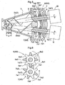
- three sets of the first abutment members 6 and the second abutment members 7 are provided along the longitudinal direction of each rotor shaft 1. And, the positions of projecting portions 6a1 of the first abutment member 6 belonging to the base end side set (outline portions in FIG. 8 ) and the positions of projecting portions 6a2 of the first abutment member 6 belonging to the intermediate side set (shaded portions in FIG. 8 ) adjacent to the base end side set and the positions of projecting portions 6a3 of the first abutment member 6 belonging to the leading end side set (meshed portions in FIG. 8 ) adjacent to the intermediate side set are rendered different from each other in the peripheral direction as seen along the axis of the one rotor shaft.
- the positions of projecting portions 7a1 of the second abutment member 7 belonging to the base end side set and the positions of projecting portions 7a2 of the second abutment member 7 belonging to the intermediate side set adjacent to the base end side set and the positions of the projecting portions 7a3 of the second abutment member 7 belonging to the leading end side set adjacent to the intermediate side set are rendered different from each other in the peripheral direction as seen along the axis of the other rotor shaft.
- the first abutment member 6 belonging to the base end side set comprise three trapezoidal-shaped projecting portions 6a1 peripherally equidistantly disposed on a cylindrical boss portion 6b1 mounted on the one rotor shaft 1a.
- the first abutment member 6 belonging to the intermediate side set comprise three trapezoidal-shaped projecting portions 6a2 peripherally equidistantly disposed on a cylindrical boss portion 6b2 mounted on the one rotor shaft 1a.
- the first abutment member 6 belonging to the leading end side set comprise three trapezoidal-shaped projecting portions 6a3 peripherally equidistantly disposed on a cylindrical boss portion 6b3 mounted on the one rotor shaft 1a.
- the second abutment member 7 belonging to the base end side set comprise three trapezoidal-shaped projecting portions 7a1 peripherally equidistantly disposed on a cylindrical boss portion 7b1 mounted on the other rotor shaft 1b.
- the second abutment member 7 belonging to the intermediate side set comprise three trapezoidal-shaped projecting portions 7a2 peripherally equidistantly disposed on a cylindrical boss portion 7b2 mounted on the other rotor shaft 1b.
- the second abutment member 7 belonging to the leading end side set comprise three trapezoidal-shaped projecting portions 7a3 peripherally equidistantly disposed on a cylindrical boss portion 7b3 mounted on the other rotor shaft 1b.
- first abutment member 6 belonging to the base end side set and the first abutment member 6 belong to the intermediate side set and the first abutment member 6 belong to the leading end side set are disposed with a phase difference of 40 degrees between these first abutment members 6 as seen along the axial direction of the one rotor shaft.
- second abutment member 7 belonging to the base end side set and the second abutment member 7 belonging to the intermediate side set and the second abutment member 7 belong to the leading end side set are disposed with a phase difference of 40 degrees between these second abutment members 7 as seen along the axial direction of the other rotor shaft.
- the number of the sets of the first abutment members 6 and the second abutment members 7 is not limited to 2 or 3, but may be more. In such case, an arrangement will be made such that the first abutment member 6 of each one of the plurality of sets is disposed with an offset in phase as seen in the direction of the one rotor shaft axis by an angle obtained by dividing the angle formed between its projecting portions 6a peripherally adjacent each other by the number of the sets of the first abutment members 6.
- the present invention is useful as a two-shaft extruder having simple construction, yet capable of efficient and effective extrusion.
Description
- The present invention relates to a two-shaft extruder comprising a pair of rotor shafts rotatably disposed with a distance therebetween diminishing toward the leading ends thereof, a screw blade mounted to the leading end of each one of the pair of rotor shafts, one screw blade intruding into the pitch of the other screw blade; and a drive unit mounted the base end of each one of the pair of rotor shafts for rotatably driving the rotor shaft associated therewith.
- Such two-shaft extruder is configured to be capable of extruding an amount of high-viscosity substance such a un-formed rubber material, plastic material charged therein while kneading the substance with the screw blades.
- Conventionally, with a two-shaft extruder, in general, as shown in
FIG. 9 , a motor M with a reduction mechanism is mounted as a drive unit to the base end of onerotor shaft 1a alone. Whereas, aconical gear 15 is attached to each one of the pair ofrotor shafts 1. In operation, as the motor M rotatably drives the onerotor shaft 1a, theother rotor shaft 1b is rotated in association therewith through the meshing engagement between the pair ofconical gears 15. In contrast, there has been proposed a different type designed to allow use of more inexpensive conical gears through reduction of the load applied to the pair ofconical gears 15 for transmitting the rotational drive force, in which a drive unit for rotatably driving a rotor shaft is mounted to the base end of each one of the pair of rotor shafts and a pair of conical gears are provided to the pair of rotor shafts respectively, such that the pair of drive units drive the pair of rotor shafts respectively in synchronism with each other through meshing engagement between the conical gears while avoiding contact between the screw blades of the rotor shafts (see e.g. Patent Document 1). - Patent Document 1: Japanese Patent Application "Kokai" No. Hei.
JPH 09164578 A -
EP 1 543 930 A2 -
US 5,803,597 discloses a machine for the extrusion of polymers and the like, comprising a pair of threaded rotors with axes, which are generally converging with respect to each other and conical gears for synchronized transmission of the movement to said rotors, wherein each rotors is made to rotate by means of its own actuating motor. -
US 5,836,681 discloses a machine with two generally converging threaded rotors for the extrusion of plastomers, elastomers and the like, comprising a structure supporting a housing containing the rotors, a casing containing a pair of reducers, a device for generating the movement, and devices for synchronized transmission thereof to the two reducers. Said devices for synchronized transmission of the movement are integral with the bottom part of said casing and have a high-speed shaft arranged along an axes forming an angle with the axes of the associated rotor and being coaxial with the high-speed shaft of the other synchronized transmission device. The high-speed drive shafts are coupled to the first shaft of the respective reducers via a bevel gear. -
WO 2007/059547 A1 discloses a device for pressing material by mixing and or agglomeration. Said device comprises a screw housing in which at least these screws are arranged next to one another. The screw threads are intermeshed. The screws rotate by means of at least one motor, wherein the material is supplied to the screws through a feed opening of the screw housing and the processed material exists the screw housing through at least one exit opening. The device is equipped with a unit which alternately and periodically causes the gap that exists between the adjacent screw threads of the screws to increase and decrease. This increase and decrease is superimposed on the rotational motion of the two screws. -
US 5,782,560 discloses an internal mixer and controller being able to control the phase difference and the speed ratio between two rotors without stopping the operation of the mixer: The mixer comprises non intermeshed first and second rotors disposed in a mixing chamber, first and second drive units, first and second phase measuring devices, first and second speed measuring devices, and a control unit for controlling the first and second drive units on the basis of signals from the first and second speed measuring devices and signals from the first and second phase measuring devices. -
EP 0860269 A2 discloses twin-screw extruder with two conical extruder screws, wherein the screw shafts form an angle with respect to each other corresponding to the conicity of the extruder screws, wherein a driving device drives the extruder shaft and wherein the second extruder shaft is coupled to the first extruder shaft via a bevel gear. -
DE 101 13 949 A1 discloses a conical twin-screw extruder having an output zone to which a gear pump is attached. The pump comprises a housing with two gear wheels on parallel axes, a feed chamber linked to the extruder output zone and a compression chamber on the output side of the gear wheels. The two extruder screws are coupled by bevel gears for synchronizing the first extruder screw with respect to the second extruder screw. -
US 4,773,763 discloses a double screw extruder including two conical extruder screws whose screw shafts are arranged at an angle to one another corresponding to the conicity of the extruder screws, and comprising a drive apparatus for driving one of the screw shafts. The other screw shaft is driven from the first screw shaft through a bevel gear drive provided with teeth arranged in herringbone or arrow fashion. - With the conventional two-shaft extruders, although differing in one transmitting drive force of one rotor shaft to the other rotor shaft, the other synchronizing each one of the pair of rotor shafts, both these extruders require that conical gears having complicated contours and requiring high working precision be provided on the pair of rotor shafts respectively; hence, there was room for improvement.
- Further, the conical gear requires a gear box for oil bathing with lubricant oil because of the constant meshing between the gears, and provision of the gear box leads to need to provide separately a mechanism for preventing the lubricant oil of the gear box from entering the housing. In these ways, the constructions would tend to be complicated.
- The present invention has been made in view of the above-described state of the art and its object is to provide a two-shaft extruder having simple construction, yet capable of efficient and effective extrusion.
- A two-shaft extruder relating to the present invention comprises according to
claim 1 a pair of rotor shafts rotatably disposed with a distance therebetween diminishing toward the leading ends thereof, a screw blade mounted to the leading end of each one of the pair of rotor shafts, one screw blade intruding into the pitch of the other screw blade; and a drive unit mounted the base end of each one of the pair of rotor shafts for rotatably driving the rotor shaft associated therewith. There is provided a screw blade contact preventing mechanism configured to allow a predetermined phase difference between the pair of rotor shafts, while inhibiting a phase difference greater than the predetermined phase difference when the pair of rotor shafts are rotatably driven respectively. - That is, since there is provided a screw blade contact preventing mechanism configured to allow a predetermined phase difference between the pair of rotor shafts, while inhibiting a phase difference greater than the predetermined phase difference when the pair of rotor shafts are rotatably driven respectively, it becomes possible to simplify the construction by omitting the conical gears. And, at the same time, with setting, as the predetermined phase difference, such an appropriate phase difference as to be capable of inhibiting inadvertent contact between the screw blades, efficient and effective extrusion is made possible with prevention of mutual contact between the screw blades.
- Further, due to omitting the conical gears, the gear box for lubricant oil bathing and the mechanism for preventing entrance of lubricant oil of the gear box into the housing can be omitted also, so that the construction can be further simplified.
- According to the present invention, in addition to the feature described above, said screw blade contact preventing mechanism includes:
- a first abutment member comprised of a plurality of projecting portions formed in one rotor shaft along the peripheral direction thereof and equidistantly or substantially equidistantly from each other; and
- a second abutment member comprised of a plurality of projecting portions formed in the other rotor shaft along the peripheral direction thereof and equidistantly or substantially equidistantly from each other;
- a path of the projecting portions of the first abutment member and a path of the projecting portions of the second abutment member are configured to interfere with each other; and
- between a projecting portion of the first abutment member and a projecting portion of the second abutment member peripherally opposed thereto, there is provided a gap for allowing the predetermined phase difference between the pair of rotor shafts, while inhibiting a phase difference greater than the predetermined phase difference.
- That is, since a gap is provided between a projecting portion of the first abutment member and a projecting portion of the second abutment member peripherally opposed thereto, no meshing engagement occurs between the projecting portion of the first abutment member and the projecting portion of the second abutment member peripherally opposed thereto. Hence, the first abutment member and the second abutment member can be provided by a simple work not requiring high precision, i.e. the work of providing a plurality of projecting portions in peripheral juxtaposition on each rotor shaft.
- Moreover, since a greater than predetermined amount phase difference is prevented between the pair of rotor shafts through the abutment between a projecting portion of the first abutment member and a projecting portion in the second abutment member peripherally opposed thereto, inadvertent contact or collision between the screw blades can be prevented, thus making effective and efficient extruding operation possible.
- In addition, as the projecting portion of the first abutment member moves within the gap provided between this projecting portion and the peripherally opposed projecting portion of the second abutment member, the predetermined phase difference between the pair of rotor shafts is allowed. Therefore, the distance in the longitudinal direction of each rotor shaft between one screw blade and the other screw blade intruding into the pitch of the one screw blade varies. With this arrangement, there can be expected achievement of such advantageous effects as enhanced kneading effect for further kneading an amount of highly viscous substance entrapped between these screw blades, a cleaning effect of removing any amount of highly viscous substance adhering to the rotor shaft by the peripheral edge of the screw blade moving along the rotor shaft.
- According to a further feature of the present invention, in addition to the feature described above, a plurality of sets of the first abutment members and the second abutment members are provided along the longitudinal direction of each rotor shaft;
the projecting portions of the first abutment member belonging in a certain set are made different in position peripherally as seen in the axial direction of the one rotor shaft than the projecting portions of the first abutment member belonging in another set adjacent thereto; and
the projecting portions of the second abutment member belonging in a certain set are made different in position peripherally as seen in the axial direction of the other rotor shaft than the projecting portions of the second abutment member belonging in another set adjacent thereto. - That is, since a plurality of sets of the first abutment members and the second abutment members are provided along the longitudinal direction of each rotor shaft, the projecting portions of the first abutment member belonging in a certain set are made different in position peripherally as seen in the axial direction of the one rotor shaft than the projecting portions of the first abutment member belonging in another set adjacent thereto and the projecting portions of the second abutment member belonging in a certain set are made different in position peripherally as seen in the axial directing portion of the other rotor shaft than the projecting portions of the second abutment member belonging in another set adjacent thereto, even if a projecting portion of the first abutment member of a certain set inadvertently fails to abut the second abutment member of that set and bypasses it via the gap, the projecting portion of the first abutment member belonging in the adjacent set will abut the second abutment member in that set, thus preventing a phase difference greater than the predetermined phase difference between the pair of rotor shafts, thus reliably preventing the phase difference between the pair of rotor shafts from becoming greater than the predetermined phase difference.
- According another feature of the present invention, in addition to the features described above, the extruder further comprises:
- a rotational speed detecting means for detecting a rotational speed of each one of the first abutment member and the second abutment member; and
- a controlling means for calculating a cycle ratio between the cycle of the first abutment member and the cycle of the second abutment member from the rotational speeds detected by the rotational speed detecting means and also for executing synchronization control scheme for each one of the pair of drive units such that said cycle ratio becomes equal to 1 (one).
- That is, since there are provided a rotational speed detecting means for detecting a rotational speed of each one of the first abutment member and the second abutment member and a controlling means for calculating a cycle ratio between the cycle of the first abutment member and the cycle of the second abutment member from the rotational speeds detected by the rotational speed detecting means and also for executing synchronization control scheme for each one of the pair of drive units such that said cycle ratio becomes equal to 1 (one), in comparison with an alternative arrangement wherein a phase difference between the pair of rotor shafts is detected by a position detecting means such as a rotary encoder and the respective rotational speeds of the pair of rotor shafts are detected by a rotational speed detecting means such as a tachometer and synchronization control scheme is executed for each one of the drive units such that the phase difference between the pair of rotor shafts becomes equal to 0 (zero), the position detecting means can be omitted. Moreover, the synchronization control is made possible with the simple control scheme of calculating the cycle ratio between the cycle of the first abutment member and the cycle of the second abutment member and rendering this cycle ratio 1 (one).
- According to a further feature of the present invention, in addition to the previous features described above, the extruder further comprises:
- a phase difference generating commanding means for issuing a phase difference generating command; and
- wherein in response to input of the phase difference generating command to said phase difference generating commanding means, said controlling means executes a phase difference generating control scheme for each one of the pair of drive units with priority over said synchronization control scheme such that the predetermined phase difference is generated between the pair of rotor shafts.
- Since there is provided a phase difference generating commanding means for issuing a phase difference generating command and in response to input of the phase difference generating command to said phase difference generating commanding means, said controlling means executes a phase difference generating control scheme for each one of the pair of drive units with priority over said synchronization control scheme such that the predetermined phase difference is generated between the pair of rotor shafts, by causing the phase difference generating command by the phase difference generating commanding means, it is possible to positively cause the above-described enhanced kneading effect and the cleaning effect to be provided as needed.
-
- [
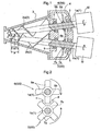
FIG. 1 ] is a general plane view of a two-shaft extruder according to a first embodiment, - [
FIG. 2 ] is a front view showing a first abutment member and a second abutment member in the first embodiment, - [
FIG. 3 ] is a view showing screw blades and rotor shafts, - [
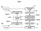
FIG. 4 ] is a control block diagram, - [
FIG. 5 ] is a general plane view showing a two-shaft extruder according to a second embodiment, - [
FIG. 6 ] is a front view showing a set of a first abutment member and a second abutment member in the second embodiment, - [
FIG. 7 ] is a general plane view showing a two-shaft extruder according to a third embodiment, - [
FIG. 8 ] is a front view showing a set of a first abutment member and a second abutment member in the third embodiment, and - [
FIG. 9 ] is a general plane view showing a two-shaft extruder having a conventional construction. - Next, a two-shaft extruder relating to the present invention will be described.
- As shown in
FIG. 1 and FIG. 2 , a two-shaft extruder is for use in extruding an amount of high-viscosity substance such as un-formed rubber material, plastic material which has been kneaded by a kneading machine such as a mixer, a kneader, etc. The two-shaft extruder includes such components as a pair ofrotor shafts 1 rotatably disposed with a distance therebetween diminishing toward the leading ends thereof, a pair ofscrew blades 2 mounted to the respective leading ends of the pair ofrotor shafts 1, a pair of motors M with reduction mechanism provided at the respective base ends of the pair ofrotor shafts 1 as a pair of drive units for rotatably driving therotor shafts 1 respectively, and so on. - Each
rotor shaft 1 has an approximately cylindrical shape with a tapered leading end. Thescrew blade 2 is configured as a variable pitch type having its pitch width P progressively decreasing toward the leading end and its flight height reducing toward the same. Between the pairedrotor shafts 1, theother screw blade 2b intrudes into the pitch P of onescrew blade 2a and the onescrew blade 2a intrudes into the pitch P of theother screw blade 2b so that the peripheral edge of thescrew blade 2 is disposed in close vicinity of the outer peripheral face of therotor shaft 1. Ahousing 3 is provided for accommodating therein therotor shafts 1 and thescrew blades 2. And, an amount of high-viscous substance or material can be charged from above thehousing 3. To the base end of thishousing 3, there is mounted an extrudermain body 4. The base ends of therotor shafts 1 extend through the extrudermain body 4 andbearings 5 are provided between base ends of therotor shafts 1 and the extrudermain body 4, so that the extrudermain body 4 rotatably supports therotor shafts 1. And, at positions offset toward the base ends from the center portions of therotor shafts 1, there are mounted afirst abutment member 6 and asecond abutment member 7 to be described later. - The
first abutment member 6 and thesecond abutment member 7 are provided in aninner space 4a of the extrudermain body 4. Thefirst abutment member 6 is constituted of a plurality of projectingportions 6a formed on onerotor shaft 1a equidistantly in the peripheral direction. Thesecond abutment member 7 is constituted of a plurality of projectingportions 7a formed on theother rotor shaft 1b equidistantly in the peripheral direction. And, arrangement is provided such that the path of the projectingportions 6a of thefirst abutment member 6 and the path of the projectingportions 7a of thesecond abutment member 7 interfere with each other. Between a projectingportion 6a of thefirst abutment member 6 and a projectingportion 7a of thesecond abutment member 7 peripherally opposed thereto, there is provided a gap (d) for allowing a predetermined phase difference between the pair ofrotor shafts 1, while preventing any phase difference greater than the predetermined phase difference. These together constitute a screw blade contact preventing mechanism SS for allowing a predetermined phase difference between the pair ofrotor shafts 1, while preventing any phase difference greater than the predetermined phase difference, when the pair ofrotor shafts 1 are rotatably driven respectively. - Referring more particularly, the
first abutment member 6 comprises four projectingportions 6a formed peripherally equidistantly on acylindrical boss portion 6b attached to the onerotor shaft 1a, each projectingportion 6a having a rectangular plate-like shape with one corner removed therefrom. Similarly, thesecond abutment member 7 comprises four projectingportions 7a formed peripherally equidistantly on acylindrical boss portion 7b attached to theother rotor shaft 1b, each projectingportion 7a having a rectangular plate-like shape with one corner removed therefrom. - And, as shown in
FIG. 1, FIG. 2 andFIG. 3 , if theother rotor shaft 1b is rotated forwardly while the onerotor shaft 1a is stopped in its rotation thereby to provide a phase difference of 60-degree advanced (seeFIG. 3 (b) ) from the normal phase (seeFIG. 3 (a) ) between the pair ofrotor shafts 1, the projectingportion 7a of thesecond abutment member 7 mounted on theother rotor shaft 1b is moved in the gap (d) provided between this projectingportion 7a and the projectingportion 6a of thefirst abutment member 6 peripherally opposed thereto, thereby allowing a predetermined phase difference between these pairedrotor shafts 1. Therefore, distances P1, P2 longitudinally of therespective rotor shaft 1 between the onescrew blade 2a and theother screw blade 2b intruding into the pitch P of the onescrew blade 2a will vary, thereby to provide an enhanced kneading effect for providing enhanced kneading of an amount of high-viscous substance entrapped between thesescrew blades 2 and the cleaning effect of the peripheral edge of thescrew blade 2 moving along the outer peripheral face of therotor shaft 1 to remove or scrape off an amount of high-viscous substance adhering to thisrotor shaft 1. At the same time, as the projectingportion 7a of thesecond abutment member 7 comes into abutment against the projectingportion 6a of thefirst abutment member 6 peripherally opposed thereto, thereby to prevent any phase difference greater than the predetermined phase difference between the pair ofrotor shafts 1. Therefore, inadvertent contact or collision between thescrew blade 2 can be effectively prevented and the extrusion operation can proceed in a smooth and effective manner. Incidentally, though not discussed in details, similar effects can be expected to be obtained also when theother rotor shaft 1b is rotated in reverse while the onerotor shaft 1a is stopped in its rotation, thus providing a phase difference of 60 degrees lagged from the normal phase (seeFIG. 3 (a) ) between the pair of rotor shafts 1 (seeFIG. 3 (c) ). - It should be noted here that the predetermined phase difference between the pair of
rotor shafts 1 is not limited to the 60 degrees phase difference described above, but may vary as desired and/or appropriately, in accordance with such factors as the torsion angle, the flight height of thescrew blade 2. - Next, a control construction of the two-shaft extruder will be explained additionally.
- As shown in
FIG. 4 , the construction includes an unillustrated command switch as a phase difference generating commanding means for issuing a phase difference generating command, oneproximity sensor 9a disposed in close proximity of the projectingportion 6a of thefirst abutment member 6, one rotationalspeed determining section 10a for determining a rotational speed of thefirst abutment member 6 based on detection information from theproximity sensor 9a and an unillustrated timer, theother proximity sensor 9b disposed in close proximity of the projectingportion 7a of thesecond abutment member 7, the other rotationalspeed determining section 10b for determining a rotational speed of thesecond abutment member 7 based on detection information from theproximity sensor 9b and an unillustrated timer. The construction further includes a calculatingsection 11 for calculating a cycle ratio Ta/Tb between a cycle Ta of thefirst abutment member 6 and a cycle Tb of thesecond abutment member 7, based on the rotational speeds of the first andsecond abutment members speed determining sections speed commanding section 12a for issuing, to one motor Ma, a speed increasing/decreasing command for increasing/decreasing the rotational speed of this one motor Ma based on the cycle ratio Ta/Tb calculated by the calculatingsection 11, and the other speedcommanding section 12b for issuing, to the other motor Mb, a speed increasing/decreasing command for increasing/decreasing the rotational speed of this other motor Mb based on the cycle ratio Ta/Tb calculated by the calculatingsection 11. - Therefore, the
proximity sensors speed determining sections first abutment member 6 and thesecond abutment member 7. The rotationalspeed determining sections section 11, and thespeed commanding sections proximity sensors - And, when no phase difference generating command is inputted thereto by the commanding switch, the controlling apparatus H calculates the cycle ratio Ta/Tb between the cycle Ta of the
first abutment member 6 and the cycle Tb of thesecond abutment member 7 based on the rotational speeds detected by the rotational speed detecting means and also issues a speed increasing/decreasing command to the pair of motors M respectively so that the cycle ratio Ta/Tb may become 1 (one), thereby to execute a synchronization control scheme for driving the pair of motors M respectively. Whereas, if a phase difference generating command is inputted thereto by the commanding switch, the controlling apparatus H issues a speed increasing/decreasing command to the pair of motors M respectively so as to execute a phase difference generating control scheme in such a manner as to generate the predetermined phase difference between the pair ofrotor shafts 1, with priority over the synchronization control scheme described above. Therefore, under the normal condition, the pair of motors M are synchronized with each other and as a worker, monitoring the conditions of therotor shafts 1 and/or thescrew blades 2, will operate the commanding switch to issue the phase difference generating command, so that an enhanced kneading effect and/or cleaning effect can be provided as needed or desired. - Referring more specifically, in the absence of input of the phase difference generating command by the commanding switch, for instance, the
first abutment member 6 will be rotated by 1/4 rotation and the oneproximity sensor 9a detects the cycle (0.25 Ta) of thefirst abutment member 6. When thesecond abutment member 7 is rotated by 1/4 rotation and theother proximity sensor 9b detects the cycle (0.25 Tb) of thesecond abutment member 7. The controlling apparatus will calculate the cycle ratio Ta/Tb between the cycle (0.25Ta) in the case of the 1/4 rotation of thefirst abutment member 6 and the cycle (0.25 Tb) in the case of the 1/4 rotation of thesecond abutment member 7. Then, if this cycle ratio Ta/Tb is smaller than 1, that is, the phase of thefirst abutment member 6 has advanced at the time of the 1/4 rotations of thefirst abutment member 6 and thesecond abutment member 7, speed increasing/decreasing commands will be issued respectively to the pair of motors M so that the cycle ratio Ta/Tb between the cycle (0.5Ta) at the time of 1/2 rotation of thefirst abutment member 6 and the cycle (0.5Tb) at the time of 1/2 rotation of thesecond abutment member 7 may become 1 (one). When a phase difference generating command is issued by the commanding switch, the speed increasing/decreasing commands are issued to the respective motors M so as to generate the predetermined phase difference between the pair ofrotor shafts 1. - Next, there will be described a screw blade contact preventing mechanism SS relating to the present invention.
- As shown in
FIG. 5 and FIG. 6 , two sets of thefirst abutment members 6 and thesecond abutment members 7 are provided along the longitudinal direction of each rotor shaft 1 (that is, the direction along the bisector dividing the internal angle formed between the pair ofrotor shafts 1 into two equal angles). And, the positions of projecting portions 6a1 of thefirst abutment member 6 belonging to the base end side set (outline portions inFIG. 6 ) and the positions of projecting portions 6a2 of thefirst abutment member 6 belonging to the leading end side set (shaded line portions inFIG. 6 ) adjacent to the base end side set are rendered different from each other in the peripheral direction as seen along the axis of the one rotor shaft. Similarly, the positions of projecting portions 7a1 of thesecond abutment member 7 belonging to the base end side set and the positions of projecting portions 7a2 of thesecond abutment member 7 belonging to the leading end side set adjacent to the base end side set are rendered different from each other in the peripheral direction as seen along the axis of the other rotor shaft. - More particularly, the
first abutment member 6 belonging to the base end side set comprise four trapezoidal-shaped projecting portions 6a1 peripherally equidistantly disposed on a cylindrical boss portion 6b1 mounted on the onerotor shaft 1a. Thefirst abutment member 6 belonging to leading end side set comprise four trapezoidal-shaped projecting portions 6a2 peripherally equidistantly disposed on a cylindrical boss portion 6b2 mounted on the onerotor shaft 1a. Thesecond abutment member 7 belonging to the base end side set comprise four trapezoidal-shaped projecting portions 7a1 peripherally equidistantly disposed on a cylindrical boss portion 7b1 mounted on theother rotor shaft 1b. Thesecond abutment member 7 belonging to the leading end side set comprise four trapezoidal-shaped projecting portions 7a2 peripherally equidistantly disposed on a cylindrical boss portion 7b2 mounted on theother rotor shaft 1b. - And, the
first abutment member 6 belonging to the base end side set and thefirst abutment member 6 belong to the leading end side set are disposed with a phase difference of 45 degrees between thesefirst abutment members 6 as seen along the axial direction of the one rotor shaft. And, thesecond abutment member 7 belonging to the base end side set and thesecond abutment member 7 belong to the leading end side set are disposed with a phase difference of 45 degrees between thesesecond abutment members 7 as seen along the axial direction of the other rotor shaft. - Incidentally, the phase difference to be provided between the
first abutment members 6 or between thesecond abutment members 7 is not limited to the 45 degree phase difference described above. However, such angle (45 degrees) is preferred in view of reliably preventing a phase difference (e.g. about 60 degrees) greater than the predetermined phase difference between the pair of rotor shafts. - Next, there will be described a screw blade contact preventing mechanism SS relating to the present invention.
- As shown in
FIG. 7 and FIG. 8 , three sets of thefirst abutment members 6 and thesecond abutment members 7 are provided along the longitudinal direction of eachrotor shaft 1. And, the positions of projecting portions 6a1 of thefirst abutment member 6 belonging to the base end side set (outline portions inFIG. 8 ) and the positions of projecting portions 6a2 of thefirst abutment member 6 belonging to the intermediate side set (shaded portions inFIG. 8 ) adjacent to the base end side set and the positions of projecting portions 6a3 of thefirst abutment member 6 belonging to the leading end side set (meshed portions inFIG. 8 ) adjacent to the intermediate side set are rendered different from each other in the peripheral direction as seen along the axis of the one rotor shaft. Similarly, the positions of projecting portions 7a1 of thesecond abutment member 7 belonging to the base end side set and the positions of projecting portions 7a2 of thesecond abutment member 7 belonging to the intermediate side set adjacent to the base end side set and the positions of the projecting portions 7a3 of thesecond abutment member 7 belonging to the leading end side set adjacent to the intermediate side set are rendered different from each other in the peripheral direction as seen along the axis of the other rotor shaft. - More particularly, the
first abutment member 6 belonging to the base end side set comprise three trapezoidal-shaped projecting portions 6a1 peripherally equidistantly disposed on a cylindrical boss portion 6b1 mounted on the onerotor shaft 1a. Thefirst abutment member 6 belonging to the intermediate side set comprise three trapezoidal-shaped projecting portions 6a2 peripherally equidistantly disposed on a cylindrical boss portion 6b2 mounted on the onerotor shaft 1a. Thefirst abutment member 6 belonging to the leading end side set comprise three trapezoidal-shaped projecting portions 6a3 peripherally equidistantly disposed on a cylindrical boss portion 6b3 mounted on the onerotor shaft 1a. Thesecond abutment member 7 belonging to the base end side set comprise three trapezoidal-shaped projecting portions 7a1 peripherally equidistantly disposed on a cylindrical boss portion 7b1 mounted on theother rotor shaft 1b. Thesecond abutment member 7 belonging to the intermediate side set comprise three trapezoidal-shaped projecting portions 7a2 peripherally equidistantly disposed on a cylindrical boss portion 7b2 mounted on theother rotor shaft 1b. Thesecond abutment member 7 belonging to the leading end side set comprise three trapezoidal-shaped projecting portions 7a3 peripherally equidistantly disposed on a cylindrical boss portion 7b3 mounted on theother rotor shaft 1b. - And, the
first abutment member 6 belonging to the base end side set and thefirst abutment member 6 belong to the intermediate side set and thefirst abutment member 6 belong to the leading end side set are disposed with a phase difference of 40 degrees between thesefirst abutment members 6 as seen along the axial direction of the one rotor shaft. And, thesecond abutment member 7 belonging to the base end side set and thesecond abutment member 7 belonging to the intermediate side set and thesecond abutment member 7 belong to the leading end side set are disposed with a phase difference of 40 degrees between thesesecond abutment members 7 as seen along the axial direction of the other rotor shaft. - Incidentally, the number of the sets of the
first abutment members 6 and thesecond abutment members 7 is not limited to 2 or 3, but may be more. In such case, an arrangement will be made such that thefirst abutment member 6 of each one of the plurality of sets is disposed with an offset in phase as seen in the direction of the one rotor shaft axis by an angle obtained by dividing the angle formed between its projectingportions 6a peripherally adjacent each other by the number of the sets of thefirst abutment members 6. And, similarly, an arrangement will be made such that thesecond abutment member 7 of each one of the plurality of sets is disposed with an offset in phase as seen in the other rotor shaft axis by an angle obtained by dividing the angle formed between its projectingportions 7a peripherally adjacent each other by the number of the sets of thesecond abutment members 7. With provision of such large number of sets of thefirst abutment members 6 and thesecond abutment members 7, even a phase difference greater than the predetermined phase difference between the pair of rotor shafts can be prevented in even more reliable manner. -
- (1) In the foregoing embodiment, there have been described the arrangements wherein a plurality of projecting
portions 6a are disposed with equal peripheral distance from each other on onerotor shaft 1a and a plurality of projectingportions 7a are disposed with equal peripheral distance from each other on theother rotor shaft 1b. The present invention is not limited thereto. Alternative arrangements may be employed wherein a plurality of projectingportions 6a are disposed with substantially equal peripheral distance from each other on onerotor shaft 1a and a plurality of projectingportions 7a are disposed with substantially equal peripheral distance from each other on theother rotor shaft 1b. - (2) In the foregoing embodiment, one
proximity sensor 9a detects the projectingportion 6a of thefirst abutment member 6 and theother proximity sensor 9b detects the projectingportion 7a of thesecond abutment member 7. Instead of this construction, oneproximity sensor 9a may detect the projectingportion 6a of thefirst abutment member 6 whereas theother proximity sensor 9b detects a dog (a detection target element) provided in thesecond abutment member 7. With this arrangement, it becomes possible to match the detection timings of theproximity sensors - (3) In the foregoing embodiment, the projecting
portion 6a of thefirst abutment member 6 and the projectingportion 7a of thesecond abutment member 7 are formed like a rectangular plate with a corner thereof removed or in the trapezoidal form. The invention is not limited thereto. Instead, these projecting portions may be provided in the form of a triangle shape having straight lateral sides or a tapered shape having lateral sides thereof comprised of curves such as involutes, etc. - the present invention is useful as a two-shaft extruder having simple construction, yet capable of efficient and effective extrusion.
Claims (3)
- A two-shaft extruder comprising:a pair of rotor shafts (1, 1a, 1b) rotatably disposed with a distance therebetween diminishing toward the leading ends thereof; anda screw blade (2, 2a, 2b) mounted to the leading end of each one of the pair of rotor shafts, one screw blade (2a) intruding into the pitch (P) of the other screw blade (2b); and a drive unit (M) mounted the base end of each one of the pair of rotor shafts for rotatably driving the rotor shaft associated therewith without the use of conical gears for synchronizing the drive of the pair of rotor shafts;wherein there is provided a screw blade contact presenting mechanism (SS) configured to allow a predetermined phase difference between the pair of rotor shafts, while inhibiting a phase difference greater than the predetermined phase difference when the pair of rotor shafts are rotatably driven respectively;wherein said screw blade contact preventing mechanism includes:a first abutment member (6) comprised of a plurality of projecting portions (6a) formed in one rotor shat (1a) along the peripheral direction thereof and equidistantly or substantially equidistantly from each other; anda second abutment member (7) comprised of a plurality of projecting portions (7a) formed in the other rotor shaft (1b) along the peripheral direction thereof and equidistantly or substantially equidistantly from each other;a path of the projecting portions of the first abutment member and a path of the projecting portions of the second abutment member are configured to interfere with each other; andbetween a projecting portion of the first abutment member and a projecting portion of the second abutment member peripherally opposed thereto, there is provided a gap (d) for allowing the predetermined phase difference between the pair of rotor shafts (1), while inhibiting a phase difference greater than the predetermined phase difference;wherein a plurality of sets of the first abutment members and the second abutment members are provided along the longitudinal direction of each rotor shaft;
the projecting portions (6a1, 6a2, ...) of the first abutment member belonging in a certain set are made different in position peripherally as seen in the axial direction of the one rotor shaft (1a) than the projecting portions (6a1, 6a2, ...) of the first abutment member (6) belonging in another set adjacent thereto; and
the projecting portions (7a1, 7a2, ...) of the second abutment member (7) belonging in a certain set are made different in position peripherally as seen in the axial direction of the other rotor shaft (1b) than the projecting portions (7a1, 7a2, ...) of the second abutment member (7) belonging in another set adjacent thereto. - The two-shaft extruder according to claim 1, wherein the extruder further comprises:a rotational speed detecting means (10a, 10b) for detecting a rotational speed of each one of the first abutment member (6) and the second abutment member (7); anda controlling means (H) for calculating a cycle ratio (Ta/Tb) between the cycle (Ta) of the first abutment member (6) and the cycle (Tb) of the second abutment member (7) from the rotational speeds detected by the rotational speed detecting means (10a, 10b) and also for executing synchronization control scheme for each one of the pair of drive units (M) such that said cycle ratio (Ta/Tb) becomes equal to 1.
- The two-shaft extruder according to claim 2, wherein the extruder further comprises:a phase difference generating commanding means for issuing a phase difference generating command; andwherein in response to input of the phase difference generating command to said phase difference generating commanding means, said controlling means (H) executes a phase difference generating control scheme for each one of the pair of drive units (M) with priority over said synchronization control scheme such that the predetermined phase difference is generated between the pair of rotor shafts (1).
Applications Claiming Priority (2)
| Application Number | Priority Date | Filing Date | Title |
|---|---|---|---|
| JP2008100645A JP5027717B2 (en) | 2008-04-08 | 2008-04-08 | Twin screw extruder |
| PCT/JP2008/071418 WO2009125514A1 (en) | 2008-04-08 | 2008-11-26 | Two-shaft extruder |
Publications (3)
| Publication Number | Publication Date |
|---|---|
| EP2269802A1 EP2269802A1 (en) | 2011-01-05 |
| EP2269802A4 EP2269802A4 (en) | 2013-12-18 |
| EP2269802B1 true EP2269802B1 (en) | 2015-08-12 |
Family
ID=41161654
Family Applications (1)
| Application Number | Title | Priority Date | Filing Date |
|---|---|---|---|
| EP08873882.8A Not-in-force EP2269802B1 (en) | 2008-04-08 | 2008-11-26 | Two-shaft extruder |
Country Status (6)
| Country | Link |
|---|---|
| US (1) | US8905623B2 (en) |
| EP (1) | EP2269802B1 (en) |
| JP (1) | JP5027717B2 (en) |
| KR (1) | KR101527252B1 (en) |
| CN (1) | CN101998901B (en) |
| WO (1) | WO2009125514A1 (en) |
Families Citing this family (15)
| Publication number | Priority date | Publication date | Assignee | Title |
|---|---|---|---|---|
| JP5027717B2 (en) * | 2008-04-08 | 2012-09-19 | 株式会社モリヤマ | Twin screw extruder |
| JP2013146920A (en) * | 2012-01-19 | 2013-08-01 | Kankyo Create:Kk | Method for manufacturing chaff-containing resin composition, chaff-containing resin composition, and molded article |
| JP2014019168A (en) * | 2012-07-12 | 2014-02-03 | Nissan Motor Co Ltd | Drive power distribution device |
| JP6066183B2 (en) * | 2013-01-23 | 2017-01-25 | 日本スピンドル製造株式会社 | Screw shaft support structure |
| JP5984186B2 (en) * | 2013-03-07 | 2016-09-06 | 日本スピンドル製造株式会社 | Twin screw extruder |
| CN103878373A (en) * | 2014-03-25 | 2014-06-25 | 萍乡亘易隆实业有限公司 | Double-screw pelletizer based on inorganic powder |
| JP6202624B2 (en) * | 2014-06-30 | 2017-09-27 | 日本スピンドル製造株式会社 | Twin screw extruder |
| RU2605910C2 (en) * | 2015-04-02 | 2016-12-27 | Егор Владимирович Кулигин | Device for preparation of moulding mixture for making articles from composite material (versions) |
| CN106891505B (en) * | 2017-04-12 | 2018-10-26 | 许梦艳 | A kind of bipyramid adjustable speed screw extruder |
| TWM551971U (en) * | 2017-08-24 | 2017-11-21 | 周延儒 | Continuous supercritical foaming and mixing-extruding equipment |
| JP2020001176A (en) * | 2018-06-25 | 2020-01-09 | 株式会社神戸製鋼所 | Screw-type extruder |
| FR3093457A1 (en) * | 2019-03-06 | 2020-09-11 | Compagnie Generale Des Etablissements Michelin | Twin Screw Mixing and Extrusion Machine with Removable Elements |
| IT202000003413A1 (en) * | 2020-02-19 | 2021-08-19 | Sancassiano Spa | MIXING MACHINE |
| CN115052725A (en) * | 2020-02-20 | 2022-09-13 | 波米尼橡胶及塑料有限责任公司 | Apparatus and method for mixing elastomeric materials |
| RU199031U1 (en) * | 2020-04-20 | 2020-08-07 | Егор Владимирвич Кулигин | MOLDING MIXTURE PREPARATION DEVICE |
Citations (3)
| Publication number | Priority date | Publication date | Assignee | Title |
|---|---|---|---|---|
| US4773763A (en) * | 1987-01-13 | 1988-09-27 | Johannes Weber | Double screw extruder |
| EP0860269A2 (en) * | 1997-02-22 | 1998-08-26 | REHAU AG + Co | Twin screw extruder |
| DE10113949A1 (en) * | 2001-03-22 | 2002-09-26 | Krupp Elastomertechnik Gmbh | Rubber straining machine comprises a conical twin screw extruder and a gear pump with filtering screen in a compression chamber after the gear wheels |
Family Cites Families (60)
| Publication number | Priority date | Publication date | Assignee | Title |
|---|---|---|---|---|
| US363953A (en) * | 1887-05-31 | Georges alexis-godillot | ||
| US617735A (en) * | 1899-01-17 | godfrey | ||
| US970240A (en) * | 1910-05-23 | 1910-09-13 | Chauncey W Kilborn | Pug-mill and stone-separator. |
| US2041619A (en) * | 1935-04-20 | 1936-05-19 | Clarence M Steele | Clay working machine |
| US2466934A (en) * | 1946-01-05 | 1949-04-12 | Charles E Dellenbarger | Extruding machine for plastic material |
| GB1094035A (en) * | 1964-03-23 | 1967-12-06 | Kawasaki Kokuki Kogyo Kabushik | Improvements in or relating to a plastics extruder |
| US3314660A (en) * | 1965-06-11 | 1967-04-18 | Atlantic Res Corp | Mixer |
| US3605188A (en) * | 1969-08-08 | 1971-09-20 | Nrm Corp | Plastic mixer and extruder |
| NL7101060A (en) * | 1970-02-10 | 1971-08-12 | ||
| BE788327A (en) * | 1971-09-02 | 1973-01-02 | Wittrock Ludwig | PROCESS AND DEVICE FOR OBTAINING THERMOPLASTIC RAW MATERIALS OR SIMILAR PRODUCTS |
| IT975950B (en) * | 1972-12-05 | 1974-08-10 | Benadi A | DEVICE FOR COMMANDING THE WIRES OF EXTRUDERS OF THE TYPE WITH TWO CO-ROTATING SCREWS PARTICULARLY FOR THERMOPLASTIC RESINS |
| DE2446420C2 (en) * | 1974-09-28 | 1982-07-15 | Krauss-Maffei AG, 8000 München | Screw extruder for processing plastics |
| JPS5549134A (en) * | 1978-10-05 | 1980-04-09 | Masao Moriyama | Continuous mixer |
| JPS5551543A (en) * | 1978-10-12 | 1980-04-15 | Toshiba Mach Co Ltd | Conical multi-shaft extruder screw |
| DE3021739A1 (en) * | 1980-06-10 | 1981-12-17 | Textruder Engineering AG, Zug | METHOD AND DOUBLE SCREW EXTRUDER FOR PROCESSING FOOD AND FEED |
| AT371058B (en) * | 1980-11-10 | 1983-05-25 | Maplan Masch Tech Anlagen | DOUBLE SCREW PRESS |
| JPS5942619B2 (en) * | 1981-03-13 | 1984-10-16 | 正夫 森山 | cone extruder |
| JPS60154030A (en) * | 1984-01-23 | 1985-08-13 | Masao Moriyama | Cone-type extruder |
| DE3420918A1 (en) * | 1984-06-05 | 1985-12-05 | Johannes Dr. 8640 Kronach Weber | Twin-screw extruder |
| JPS61206715A (en) * | 1985-03-08 | 1986-09-13 | Hitachi Zosen Corp | Screw feeder for feeding powder with pressure |
| JPS6264505A (en) * | 1985-09-18 | 1987-03-23 | Keiji Nakajima | Mixing and melting of synthetic resin and device thereof |
| DE3545339A1 (en) * | 1985-12-20 | 1987-07-02 | Krupp Koppers Gmbh | Screw conveyor for conveying finely divided solid materials |
| US4764020A (en) * | 1986-12-12 | 1988-08-16 | Masao Moriyama | Apparatus for mixing and extruding viscous liquids |
| DE3920422A1 (en) * | 1989-06-22 | 1991-01-03 | Basf Ag | Mixer for synthetic resin reagents - by feed reagents to tapered screws revolving in equal or opposite directions in tapered chamber |
| DE3940833C1 (en) | 1989-12-11 | 1990-09-27 | Rhodia Ag, 7800 Freiburg, De | |
| CA2049256A1 (en) * | 1990-08-22 | 1992-02-23 | Masao Moriyama | Twin conical screw extruder |
| DE4126390A1 (en) * | 1991-08-09 | 1993-02-11 | Werner & Pfleiderer | MIXING AND TREATMENT DEVICE WITH DISCHARGE PUMP |
| JP2962625B2 (en) * | 1992-11-16 | 1999-10-12 | 株式会社神戸製鋼所 | Cone type twin screw extruder |
| US6258302B1 (en) * | 1999-02-10 | 2001-07-10 | Spalding Sports Worldwide, Inc. | Process for producing polybutadiene golf ball cores |
| JPH06154030A (en) * | 1993-07-06 | 1994-06-03 | Dentaru Kagaku Kk | Antimicrobial apatite and antimicrobial resin containing the same |
| JP2698037B2 (en) * | 1993-09-14 | 1998-01-19 | 株式会社神戸製鋼所 | Extruder bank amount adjustment device |
| JPH07164508A (en) * | 1993-12-13 | 1995-06-27 | Kobe Steel Ltd | Drive transmission device of twin-screw extruder |
| EP0740603B1 (en) * | 1994-01-19 | 1998-11-04 | The Dow Chemical Company | Single-screw extruder method and apparatus |
| IT1270683B (en) * | 1994-10-27 | 1997-05-07 | Pomini Spa | EQUIPMENT FOR THE CONTINUOUS FEEDING OF EXTRUSION AND / OR LAMINATION MACHINES WITH VISCOUS MATERIAL SUCH AS RUBBER AND SIMILAR COMING FROM DISCONTINUOUS CYCLE MACHINES |
| JP2989110B2 (en) * | 1994-12-26 | 1999-12-13 | 株式会社日本製鋼所 | Method and apparatus for detecting presence or absence of input material in twin-shaft meshing taper screw feeder |
| US5628560A (en) * | 1995-05-24 | 1997-05-13 | American Maplan Corporation | Double-screw extruder |
| JPH091631A (en) * | 1995-06-16 | 1997-01-07 | Kobe Steel Ltd | Sheet width regulator or roller head extruder |
| IT1279066B1 (en) * | 1995-11-21 | 1997-12-04 | Pomini Spa | MACHINE FOR THE EXTRUSION OF POLYMERS AND SIMILAR WITH CONVERGENT THREADED ROTORS OPERATED EACH BY ITS OWN MOTOR OF |
| IT1277236B1 (en) * | 1995-11-21 | 1997-11-05 | Pomini Spa | MACHINE WITH TWO CONVERGENT THREADED ROTORS FOR THE EXTRUCTION OF PLASTOMERS, ELASTOMERS AND SIMILAR |
| JP2871565B2 (en) * | 1995-12-26 | 1999-03-17 | 株式会社神戸製鋼所 | Roller head extruder and control method thereof |
| JPH09300433A (en) * | 1996-05-20 | 1997-11-25 | Kobe Steel Ltd | Screw for extruder |
| US5782560A (en) * | 1996-06-24 | 1998-07-21 | Kabushiki Kaisha Kobe Seiko Sho | Internal mixer |
| DE19741674A1 (en) * | 1997-09-22 | 1999-03-25 | Haake Gmbh Geb | Mixer for viscoelastic materials |
| JPH11132166A (en) * | 1997-10-28 | 1999-05-18 | Mitsubishi Heavy Ind Ltd | Scroll type fluid machine |
| JP2000225641A (en) * | 1998-12-02 | 2000-08-15 | Ikegai Corp | Extruder |
| JP2000246731A (en) * | 1999-03-02 | 2000-09-12 | Kobe Steel Ltd | Kneading rotor and kneading machine employing this |
| JP2002144313A (en) * | 2000-08-30 | 2002-05-21 | Denso Corp | Extrusion molding machine for ceramic molding |
| JP2002355879A (en) * | 2001-05-30 | 2002-12-10 | Toshiba Mach Co Ltd | Conical screw for twin-screw extruder and extrusion molding method using the same |
| US6609819B2 (en) * | 2001-07-24 | 2003-08-26 | Wenger Mfg | Twin screw extruder with conical non-parallel converging screws |
| JP4064308B2 (en) * | 2002-07-17 | 2008-03-19 | 鈴鹿エンヂニヤリング株式会社 | Rubber kneader |
| EP1663631A1 (en) * | 2003-09-12 | 2006-06-07 | New Pressing Technology Di Babbini Maria Teresa E.C. S.r.l. | Screw press for squeezing out fibrous material |
| EP1677959B1 (en) * | 2003-10-28 | 2009-01-07 | COLMEC S.p.A. | Machine for mixing and extruding rubber-based and silicone-based plastic materials and method therefor |
| DE10359774A1 (en) | 2003-12-19 | 2005-07-14 | Thyssenkrupp Elastomertechnik Gmbh | contraption |
| DE102004012569A1 (en) * | 2004-03-12 | 2005-09-29 | A. Friedr. Flender Ag | Gearbox for a twin-screw extruder |
| JP4255873B2 (en) * | 2004-03-30 | 2009-04-15 | 株式会社神戸製鋼所 | Conical twin screw extruder and dehydrator |
| AT503371B1 (en) * | 2005-11-25 | 2010-11-15 | Schulz Helmuth Ing | DEVICE AND METHOD FOR PROCESSING MATERIAL BY MIXTURE AND / OR BZW. OR PLASTIFICATION OR AGGLOMERATION |
| US20070190198A1 (en) * | 2006-02-16 | 2007-08-16 | Hyundai Mobis Co., Ltd. | Apparatus for processing polypropylene compound containing glass bubble |
| JP5027717B2 (en) * | 2008-04-08 | 2012-09-19 | 株式会社モリヤマ | Twin screw extruder |
| JP5102168B2 (en) * | 2008-10-01 | 2012-12-19 | 株式会社モリヤマ | Method for solving trouble in sheet forming apparatus and sheet forming apparatus |
| US8328993B2 (en) * | 2009-05-18 | 2012-12-11 | Greenlight Energy Solutions, Llc | Pyrolysis reactor for processing municipal wastes |
-
2008
- 2008-04-08 JP JP2008100645A patent/JP5027717B2/en active Active
- 2008-11-26 CN CN2008801284959A patent/CN101998901B/en not_active Expired - Fee Related
- 2008-11-26 US US12/933,937 patent/US8905623B2/en not_active Expired - Fee Related
- 2008-11-26 KR KR1020107024745A patent/KR101527252B1/en active IP Right Grant
- 2008-11-26 EP EP08873882.8A patent/EP2269802B1/en not_active Not-in-force
- 2008-11-26 WO PCT/JP2008/071418 patent/WO2009125514A1/en active Application Filing
Patent Citations (3)
| Publication number | Priority date | Publication date | Assignee | Title |
|---|---|---|---|---|
| US4773763A (en) * | 1987-01-13 | 1988-09-27 | Johannes Weber | Double screw extruder |
| EP0860269A2 (en) * | 1997-02-22 | 1998-08-26 | REHAU AG + Co | Twin screw extruder |
| DE10113949A1 (en) * | 2001-03-22 | 2002-09-26 | Krupp Elastomertechnik Gmbh | Rubber straining machine comprises a conical twin screw extruder and a gear pump with filtering screen in a compression chamber after the gear wheels |
Also Published As
| Publication number | Publication date |
|---|---|
| EP2269802A4 (en) | 2013-12-18 |
| US20110091596A1 (en) | 2011-04-21 |
| EP2269802A1 (en) | 2011-01-05 |
| CN101998901A (en) | 2011-03-30 |
| JP2009248486A (en) | 2009-10-29 |
| WO2009125514A1 (en) | 2009-10-15 |
| US8905623B2 (en) | 2014-12-09 |
| KR20110002856A (en) | 2011-01-10 |
| KR101527252B1 (en) | 2015-06-16 |
| JP5027717B2 (en) | 2012-09-19 |
| CN101998901B (en) | 2013-10-02 |
Similar Documents
| Publication | Publication Date | Title |
|---|---|---|
| EP2269802B1 (en) | Two-shaft extruder | |
| EP0701662B1 (en) | Positive displacement machine with electronic motor synchronisation | |
| US9290330B2 (en) | Screw conveyer system | |
| CN102781638A (en) | Cutter device | |
| US20050041521A1 (en) | Screw-type extruding machine comprising mixing and kneading disks | |
| US8746955B2 (en) | Screw machine with at least one extension-kneading element in a flow direction | |
| JP2008183721A (en) | Extruder screw, bearing segment used for this screw, and biaxial extruder equipped with this screw | |
| US20150239166A1 (en) | Feed device for feeding fibers during the production of fiber-reinforced plastics materials | |
| JPH0347131B2 (en) | ||
| JP5683457B2 (en) | Multi-screw extruder | |
| JP5852798B2 (en) | Drive unit for twin-screw extruder capable of rotating in the same direction | |
| JP5130285B2 (en) | Screw element | |
| EP2628391B1 (en) | Method for filling sausages with paste mass and filling machine for performing this method | |
| US9346190B2 (en) | Device for processing material by mixing and/or plasticating | |
| JP2009196302A (en) | Twin screw kneading extruder and load torque calculation method in twin screw kneading extruder | |
| US20100322806A1 (en) | Arrangement including a gear pump | |
| CN102672917B (en) | Injection moulding machine, and adjusting method for injection moulding machine | |
| US20060240133A1 (en) | Installation for preparing materials | |
| JPS59209595A (en) | Synchronizer for master machine and slave machine | |
| KR101484905B1 (en) | Rotary die cutting apparatus | |
| JP3897585B2 (en) | Method for cutting molded product in extrusion molding machine | |
| JP4775228B2 (en) | Powder rolling equipment | |
| JP2001327883A (en) | Outlet gap adjusting device for gyratory crusher and its adjusting method | |
| JP2010006474A (en) | Packaging apparatus and motor controller | |
| JPS58183210A (en) | Continuous kneading extruder |
Legal Events
| Date | Code | Title | Description |
|---|---|---|---|
| PUAI | Public reference made under article 153(3) epc to a published international application that has entered the european phase |
Free format text: ORIGINAL CODE: 0009012 |
|
| 17P | Request for examination filed |
Effective date: 20101019 |
|
| AK | Designated contracting states |
Kind code of ref document: A1 Designated state(s): AT BE BG CH CY CZ DE DK EE ES FI FR GB GR HR HU IE IS IT LI LT LU LV MC MT NL NO PL PT RO SE SI SK TR |
|
| AX | Request for extension of the european patent |
Extension state: AL BA MK RS |
|
| DAX | Request for extension of the european patent (deleted) | ||
| A4 | Supplementary search report drawn up and despatched |
Effective date: 20131119 |
|
| RIC1 | Information provided on ipc code assigned before grant |
Ipc: B29C 47/40 20060101AFI20131113BHEP Ipc: B29C 47/92 20060101ALI20131113BHEP Ipc: B29C 47/08 20060101ALI20131113BHEP |
|
| 17Q | First examination report despatched |
Effective date: 20140709 |
|
| GRAP | Despatch of communication of intention to grant a patent |
Free format text: ORIGINAL CODE: EPIDOSNIGR1 |
|
| INTG | Intention to grant announced |
Effective date: 20150331 |
|
| RAP1 | Party data changed (applicant data changed or rights of an application transferred) |
Owner name: MORIYAMA COMPANY LTD. |
|
| GRAS | Grant fee paid |
Free format text: ORIGINAL CODE: EPIDOSNIGR3 |
|
| GRAA | (expected) grant |
Free format text: ORIGINAL CODE: 0009210 |
|
| AK | Designated contracting states |
Kind code of ref document: B1 Designated state(s): AT BE BG CH CY CZ DE DK EE ES FI FR GB GR HR HU IE IS IT LI LT LU LV MC MT NL NO PL PT RO SE SI SK TR |
|
| REG | Reference to a national code |
Ref country code: GB Ref legal event code: FG4D |
|
| REG | Reference to a national code |
Ref country code: CH Ref legal event code: EP |
|
| REG | Reference to a national code |
Ref country code: AT Ref legal event code: REF Ref document number: 741736 Country of ref document: AT Kind code of ref document: T Effective date: 20150815 |
|
| REG | Reference to a national code |
Ref country code: IE Ref legal event code: FG4D |
|
| REG | Reference to a national code |
Ref country code: DE Ref legal event code: R096 Ref document number: 602008039595 Country of ref document: DE |
|
| REG | Reference to a national code |
Ref country code: LT Ref legal event code: MG4D |
|
| REG | Reference to a national code |
Ref country code: AT Ref legal event code: MK05 Ref document number: 741736 Country of ref document: AT Kind code of ref document: T Effective date: 20150812 |
|
| REG | Reference to a national code |
Ref country code: NL Ref legal event code: MP Effective date: 20150812 |
|
| PG25 | Lapsed in a contracting state [announced via postgrant information from national office to epo] |
Ref country code: LT Free format text: LAPSE BECAUSE OF FAILURE TO SUBMIT A TRANSLATION OF THE DESCRIPTION OR TO PAY THE FEE WITHIN THE PRESCRIBED TIME-LIMIT Effective date: 20150812 Ref country code: GR Free format text: LAPSE BECAUSE OF FAILURE TO SUBMIT A TRANSLATION OF THE DESCRIPTION OR TO PAY THE FEE WITHIN THE PRESCRIBED TIME-LIMIT Effective date: 20151113 Ref country code: LV Free format text: LAPSE BECAUSE OF FAILURE TO SUBMIT A TRANSLATION OF THE DESCRIPTION OR TO PAY THE FEE WITHIN THE PRESCRIBED TIME-LIMIT Effective date: 20150812 Ref country code: NO Free format text: LAPSE BECAUSE OF FAILURE TO SUBMIT A TRANSLATION OF THE DESCRIPTION OR TO PAY THE FEE WITHIN THE PRESCRIBED TIME-LIMIT Effective date: 20151112 Ref country code: FI Free format text: LAPSE BECAUSE OF FAILURE TO SUBMIT A TRANSLATION OF THE DESCRIPTION OR TO PAY THE FEE WITHIN THE PRESCRIBED TIME-LIMIT Effective date: 20150812 |
|
| PG25 | Lapsed in a contracting state [announced via postgrant information from national office to epo] |
Ref country code: PT Free format text: LAPSE BECAUSE OF FAILURE TO SUBMIT A TRANSLATION OF THE DESCRIPTION OR TO PAY THE FEE WITHIN THE PRESCRIBED TIME-LIMIT Effective date: 20151214 Ref country code: ES Free format text: LAPSE BECAUSE OF FAILURE TO SUBMIT A TRANSLATION OF THE DESCRIPTION OR TO PAY THE FEE WITHIN THE PRESCRIBED TIME-LIMIT Effective date: 20150812 Ref country code: IS Free format text: LAPSE BECAUSE OF FAILURE TO SUBMIT A TRANSLATION OF THE DESCRIPTION OR TO PAY THE FEE WITHIN THE PRESCRIBED TIME-LIMIT Effective date: 20151212 Ref country code: HR Free format text: LAPSE BECAUSE OF FAILURE TO SUBMIT A TRANSLATION OF THE DESCRIPTION OR TO PAY THE FEE WITHIN THE PRESCRIBED TIME-LIMIT Effective date: 20150812 Ref country code: AT Free format text: LAPSE BECAUSE OF FAILURE TO SUBMIT A TRANSLATION OF THE DESCRIPTION OR TO PAY THE FEE WITHIN THE PRESCRIBED TIME-LIMIT Effective date: 20150812 Ref country code: SE Free format text: LAPSE BECAUSE OF FAILURE TO SUBMIT A TRANSLATION OF THE DESCRIPTION OR TO PAY THE FEE WITHIN THE PRESCRIBED TIME-LIMIT Effective date: 20150812 Ref country code: PL Free format text: LAPSE BECAUSE OF FAILURE TO SUBMIT A TRANSLATION OF THE DESCRIPTION OR TO PAY THE FEE WITHIN THE PRESCRIBED TIME-LIMIT Effective date: 20150812 |
|
| PG25 | Lapsed in a contracting state [announced via postgrant information from national office to epo] |
Ref country code: NL Free format text: LAPSE BECAUSE OF FAILURE TO SUBMIT A TRANSLATION OF THE DESCRIPTION OR TO PAY THE FEE WITHIN THE PRESCRIBED TIME-LIMIT Effective date: 20150812 |
|
| PG25 | Lapsed in a contracting state [announced via postgrant information from national office to epo] |
Ref country code: CZ Free format text: LAPSE BECAUSE OF FAILURE TO SUBMIT A TRANSLATION OF THE DESCRIPTION OR TO PAY THE FEE WITHIN THE PRESCRIBED TIME-LIMIT Effective date: 20150812 Ref country code: SK Free format text: LAPSE BECAUSE OF FAILURE TO SUBMIT A TRANSLATION OF THE DESCRIPTION OR TO PAY THE FEE WITHIN THE PRESCRIBED TIME-LIMIT Effective date: 20150812 Ref country code: DK Free format text: LAPSE BECAUSE OF FAILURE TO SUBMIT A TRANSLATION OF THE DESCRIPTION OR TO PAY THE FEE WITHIN THE PRESCRIBED TIME-LIMIT Effective date: 20150812 Ref country code: EE Free format text: LAPSE BECAUSE OF FAILURE TO SUBMIT A TRANSLATION OF THE DESCRIPTION OR TO PAY THE FEE WITHIN THE PRESCRIBED TIME-LIMIT Effective date: 20150812 |
|
| REG | Reference to a national code |
Ref country code: DE Ref legal event code: R097 Ref document number: 602008039595 Country of ref document: DE |
|
| PG25 | Lapsed in a contracting state [announced via postgrant information from national office to epo] |
Ref country code: RO Free format text: LAPSE BECAUSE OF FAILURE TO SUBMIT A TRANSLATION OF THE DESCRIPTION OR TO PAY THE FEE WITHIN THE PRESCRIBED TIME-LIMIT Effective date: 20150812 |
|
| PLBE | No opposition filed within time limit |
Free format text: ORIGINAL CODE: 0009261 |
|
| STAA | Information on the status of an ep patent application or granted ep patent |
Free format text: STATUS: NO OPPOSITION FILED WITHIN TIME LIMIT |
|
| PG25 | Lapsed in a contracting state [announced via postgrant information from national office to epo] |
Ref country code: LU Free format text: LAPSE BECAUSE OF FAILURE TO SUBMIT A TRANSLATION OF THE DESCRIPTION OR TO PAY THE FEE WITHIN THE PRESCRIBED TIME-LIMIT Effective date: 20151126 Ref country code: MC Free format text: LAPSE BECAUSE OF FAILURE TO SUBMIT A TRANSLATION OF THE DESCRIPTION OR TO PAY THE FEE WITHIN THE PRESCRIBED TIME-LIMIT Effective date: 20150812 |
|
| REG | Reference to a national code |
Ref country code: CH Ref legal event code: PL |
|
| 26N | No opposition filed |
Effective date: 20160513 |
|
| PG25 | Lapsed in a contracting state [announced via postgrant information from national office to epo] |
Ref country code: CH Free format text: LAPSE BECAUSE OF NON-PAYMENT OF DUE FEES Effective date: 20151130 Ref country code: LI Free format text: LAPSE BECAUSE OF NON-PAYMENT OF DUE FEES Effective date: 20151130 |
|
| REG | Reference to a national code |
Ref country code: IE Ref legal event code: MM4A |
|
| REG | Reference to a national code |
Ref country code: FR Ref legal event code: ST Effective date: 20160729 |
|
| PG25 | Lapsed in a contracting state [announced via postgrant information from national office to epo] |
Ref country code: SI Free format text: LAPSE BECAUSE OF FAILURE TO SUBMIT A TRANSLATION OF THE DESCRIPTION OR TO PAY THE FEE WITHIN THE PRESCRIBED TIME-LIMIT Effective date: 20150812 |
|
| PG25 | Lapsed in a contracting state [announced via postgrant information from national office to epo] |
Ref country code: IE Free format text: LAPSE BECAUSE OF NON-PAYMENT OF DUE FEES Effective date: 20151126 |
|
| PG25 | Lapsed in a contracting state [announced via postgrant information from national office to epo] |
Ref country code: FR Free format text: LAPSE BECAUSE OF NON-PAYMENT OF DUE FEES Effective date: 20151130 |
|
| PG25 | Lapsed in a contracting state [announced via postgrant information from national office to epo] |
Ref country code: BE Free format text: LAPSE BECAUSE OF FAILURE TO SUBMIT A TRANSLATION OF THE DESCRIPTION OR TO PAY THE FEE WITHIN THE PRESCRIBED TIME-LIMIT Effective date: 20150812 |
|
| PG25 | Lapsed in a contracting state [announced via postgrant information from national office to epo] |
Ref country code: BG Free format text: LAPSE BECAUSE OF FAILURE TO SUBMIT A TRANSLATION OF THE DESCRIPTION OR TO PAY THE FEE WITHIN THE PRESCRIBED TIME-LIMIT Effective date: 20150812 Ref country code: HU Free format text: LAPSE BECAUSE OF FAILURE TO SUBMIT A TRANSLATION OF THE DESCRIPTION OR TO PAY THE FEE WITHIN THE PRESCRIBED TIME-LIMIT; INVALID AB INITIO Effective date: 20081126 |
|
| PG25 | Lapsed in a contracting state [announced via postgrant information from national office to epo] |
Ref country code: CY Free format text: LAPSE BECAUSE OF FAILURE TO SUBMIT A TRANSLATION OF THE DESCRIPTION OR TO PAY THE FEE WITHIN THE PRESCRIBED TIME-LIMIT Effective date: 20150812 |
|
| PG25 | Lapsed in a contracting state [announced via postgrant information from national office to epo] |
Ref country code: MT Free format text: LAPSE BECAUSE OF FAILURE TO SUBMIT A TRANSLATION OF THE DESCRIPTION OR TO PAY THE FEE WITHIN THE PRESCRIBED TIME-LIMIT Effective date: 20150812 Ref country code: TR Free format text: LAPSE BECAUSE OF FAILURE TO SUBMIT A TRANSLATION OF THE DESCRIPTION OR TO PAY THE FEE WITHIN THE PRESCRIBED TIME-LIMIT Effective date: 20150812 |
|
| REG | Reference to a national code |
Ref country code: DE Ref legal event code: R079 Ref document number: 602008039595 Country of ref document: DE Free format text: PREVIOUS MAIN CLASS: B29C0047400000 Ipc: B29C0048400000 |
|
| PGFP | Annual fee paid to national office [announced via postgrant information from national office to epo] |
Ref country code: GB Payment date: 20181121 Year of fee payment: 11 Ref country code: IT Payment date: 20181122 Year of fee payment: 11 |
|
| GBPC | Gb: european patent ceased through non-payment of renewal fee |
Effective date: 20191126 |
|
| PG25 | Lapsed in a contracting state [announced via postgrant information from national office to epo] |
Ref country code: IT Free format text: LAPSE BECAUSE OF NON-PAYMENT OF DUE FEES Effective date: 20191126 Ref country code: GB Free format text: LAPSE BECAUSE OF NON-PAYMENT OF DUE FEES Effective date: 20191126 |
|
| PGFP | Annual fee paid to national office [announced via postgrant information from national office to epo] |
Ref country code: DE Payment date: 20211005 Year of fee payment: 14 |
|
| REG | Reference to a national code |
Ref country code: DE Ref legal event code: R119 Ref document number: 602008039595 Country of ref document: DE |
|
| PG25 | Lapsed in a contracting state [announced via postgrant information from national office to epo] |
Ref country code: DE Free format text: LAPSE BECAUSE OF NON-PAYMENT OF DUE FEES Effective date: 20230601 |