EP2269799B1 - Dispositif de fabrication de produits finis en forme de crayon par moulage par injection - Google Patents
Dispositif de fabrication de produits finis en forme de crayon par moulage par injection Download PDFInfo
- Publication number
- EP2269799B1 EP2269799B1 EP09008607.5A EP09008607A EP2269799B1 EP 2269799 B1 EP2269799 B1 EP 2269799B1 EP 09008607 A EP09008607 A EP 09008607A EP 2269799 B1 EP2269799 B1 EP 2269799B1
- Authority
- EP
- European Patent Office
- Prior art keywords
- injection
- plate
- molding tool
- skin
- cavity
- Prior art date
- Legal status (The legal status is an assumption and is not a legal conclusion. Google has not performed a legal analysis and makes no representation as to the accuracy of the status listed.)
- Not-in-force
Links
Images




Classifications
-
- B—PERFORMING OPERATIONS; TRANSPORTING
- B29—WORKING OF PLASTICS; WORKING OF SUBSTANCES IN A PLASTIC STATE IN GENERAL
- B29C—SHAPING OR JOINING OF PLASTICS; SHAPING OF MATERIAL IN A PLASTIC STATE, NOT OTHERWISE PROVIDED FOR; AFTER-TREATMENT OF THE SHAPED PRODUCTS, e.g. REPAIRING
- B29C45/00—Injection moulding, i.e. forcing the required volume of moulding material through a nozzle into a closed mould; Apparatus therefor
- B29C45/17—Component parts, details or accessories; Auxiliary operations
- B29C45/1759—Removing sprues from sprue-channels
-
- B—PERFORMING OPERATIONS; TRANSPORTING
- B29—WORKING OF PLASTICS; WORKING OF SUBSTANCES IN A PLASTIC STATE IN GENERAL
- B29C—SHAPING OR JOINING OF PLASTICS; SHAPING OF MATERIAL IN A PLASTIC STATE, NOT OTHERWISE PROVIDED FOR; AFTER-TREATMENT OF THE SHAPED PRODUCTS, e.g. REPAIRING
- B29C45/00—Injection moulding, i.e. forcing the required volume of moulding material through a nozzle into a closed mould; Apparatus therefor
- B29C45/17—Component parts, details or accessories; Auxiliary operations
- B29C45/26—Moulds
- B29C45/27—Sprue channels ; Runner channels or runner nozzles
- B29C45/2756—Cold runner channels
-
- B—PERFORMING OPERATIONS; TRANSPORTING
- B29—WORKING OF PLASTICS; WORKING OF SUBSTANCES IN A PLASTIC STATE IN GENERAL
- B29C—SHAPING OR JOINING OF PLASTICS; SHAPING OF MATERIAL IN A PLASTIC STATE, NOT OTHERWISE PROVIDED FOR; AFTER-TREATMENT OF THE SHAPED PRODUCTS, e.g. REPAIRING
- B29C45/00—Injection moulding, i.e. forcing the required volume of moulding material through a nozzle into a closed mould; Apparatus therefor
- B29C45/17—Component parts, details or accessories; Auxiliary operations
- B29C45/26—Moulds
- B29C45/27—Sprue channels ; Runner channels or runner nozzles
- B29C45/2701—Details not specific to hot or cold runner channels
- B29C45/2708—Gates
- B29C2045/2714—Gates elongated, e.g. film-like, annular
-
- B—PERFORMING OPERATIONS; TRANSPORTING
- B29—WORKING OF PLASTICS; WORKING OF SUBSTANCES IN A PLASTIC STATE IN GENERAL
- B29C—SHAPING OR JOINING OF PLASTICS; SHAPING OF MATERIAL IN A PLASTIC STATE, NOT OTHERWISE PROVIDED FOR; AFTER-TREATMENT OF THE SHAPED PRODUCTS, e.g. REPAIRING
- B29C2791/00—Shaping characteristics in general
- B29C2791/004—Shaping under special conditions
- B29C2791/006—Using vacuum
-
- B—PERFORMING OPERATIONS; TRANSPORTING
- B29—WORKING OF PLASTICS; WORKING OF SUBSTANCES IN A PLASTIC STATE IN GENERAL
- B29K—INDEXING SCHEME ASSOCIATED WITH SUBCLASSES B29B, B29C OR B29D, RELATING TO MOULDING MATERIALS OR TO MATERIALS FOR MOULDS, REINFORCEMENTS, FILLERS OR PREFORMED PARTS, e.g. INSERTS
- B29K2021/00—Use of unspecified rubbers as moulding material
- B29K2021/006—Thermosetting elastomers
Definitions
- the invention relates to an injection molding tool according to claim 1.
- the invention further relates to a method according to claim 16 for use of this injection molding tool.
- Injection molding processes are widely used, in particular in the series production of injection molded parts of all kinds. Depending on the injection-molded part to be produced, a wide variety of functions, sizes and shapes can be encountered.
- Injection molding generally takes place in a cyclic sequence which can be repeated as often as desired, wherein one or more injection-molded parts, referred to below as benefits, are produced during each cycle. It is introduced into a closed cavity, formed by a generally at least two-part mold and possibly one or more cores, liquefied sprayed under pressure until the cavity is filled, then there is a solidification process. Subsequently, the cavity is opened, which in the meantime removed to a stable form hardened benefits, and the mold closed again.
- the sprue is formed in the runner, the support system in the runner system and the benefits in corresponding cavities connected to the runner system.
- the entire cavity of such an injection molding tool thus has the sprue channel for forming the sprue, useful cavities for forming the benefits, and a cavity connecting these groove cavities with the sprue channel and forming the carrier system.
- this connecting cavity consists of individual channels.
- the molded in the runner cavity support system of the molding is in such cases of a branched structure in a flat structure over.
- JP-A-11-254486 describes an injection molding tool having a base plate assembly, a center plate, and a utility plate assembly.
- the base plate assembly has a sprue through which the spray can pass into a cavity.
- the center plate is in the closed state of the injection mold with an end face on the base plate assembly and forms a first separation surface, and abuts with an opposite end face to form a second separation surface on the utility plate assembly.
- the Fellkavtician In the closed state of the injection molding tool on the one hand by the center plate and the base plate assembly, the Fellkavtician, and on the other hand formed by the center plate together with the utility plate assembly a predetermined number of respectivelykavticianen.
- the benefits are removed from the hide by removing the benefit plate assembly from the center plate, ie by opening the injection mold in the second interface.
- the present invention has for its object to provide an injection molding tool of the type mentioned above, which allows the production of particular slender use of elastic and plastic materials in a simple manner and further related to the opening process separating the benefits of the carrier system, associated with a demolding and an application of the same allows, thereby avoiding problems of the type mentioned.
- the injection molding tool according to the invention has three subassemblies, namely a base plate arrangement, a center plate and a utility plate arrangement.
- the base plate assembly preferably comprises a skin plate and a base plate.
- the base plate is intended to be connected to a fixed part of an injection molding machine.
- a runner is incorporated, through which the sprayed, in the present case a plastic, in particular an elastomeric material, for example rubber-based, can get into a cavity.
- the sprayed material must be in a sprayable state.
- the injection mold on the center plate which abuts in the closed state of the injection mold with an end face on the base plate assembly and forms a first separation surface, and rests with an opposite end face to form a second separation surface on the third assembly, the benefit plate assembly.
- the center plate can be individually actuated and guided, in an advantageous embodiment, it is guided on the utility plate assembly.
- the fur cavity is formed by the center plate and the skin plate, and on the other hand by the center plate together with the utility plate arrangement a predetermined number of
- the center plate is formed by the center plate and the skin plate, and on the other hand by the center plate together with the utility plate arrangement a predetermined number of
- the fur cavity is connected to the runner and forms together with this the carrier system of the molding, which in the present case comprises a sprue and a so-called fur.
- the center plate and the benefit plate assembly together form a number of benefit cavities.
- dependingcorkavtician the attributable to the center plate surface portion is significantly smaller than that in the utility plate assembly, in an advantageous embodiment, it is even reduced only to a limiting surface, which is preferably a support surface.
- the center plate thus has at its two end faces which lie in the first and in the second parting surface, hollow molds, which provide a partial region for the fur and therickavticianen, wherein the depth of the use-side molds may tend to zero.
- each compound has, starting from the fur cavity, over at least a part of a length on a feed sink and opens into a profit-side inflow mouth. This is located in that region of therickavtician, which forms the support surface and is advantageously arranged centrally.
- the utility plate assembly itself consists of at least one end plate and a shank plate, the latter, in the closed state of the injection mold, on the one hand in the second separation surface on the center plate and on the other hand against the end plate.
- the face plate is in firm connection with the moving part of the injection molding machine, whereas the shank mold plate relative to this slidably mounted by a predetermined stroke, preferably guided on the Stirnformplatte, and is biased relative to the center plate.
- each support surface in the benefit cavities support the generated benefits such that when the injection mold is opened in the first interface, the benefits separate from the coat. Therefore, it is advantageous if the cross section of each support surface is a multiple of the inflow cross section, preferably more than 10 times the inflow cross section. If possible, the remaining inflow cross section is positioned coaxially to an optionally present core.
- a preferably pin-shaped core is firmly and freely cantilevered into the base plate per cavity, which protrudes through the respective inflow opening into this cavity.
- the fur cavity preferably has a two-dimensional cavity section, from which inlet depressions are formed to each inflow opening, which taper at least partially in the direction of the respective inflow opening, and thus in the flow direction of the injection molding.
- the optionally pin-shaped core can be made thicker at the height of the fur cavity, which benefits the stability, and secondly, the sprayed material can flow more easily and spread more evenly, comparable to a hopper, whereby a faster filling achieved and uneven loads on the core are largely avoided.
- filigree hollow parts which - as in the present case - require high precision, due to the high pressures and fast flow rates, the pressure differences occurring in uneven filling ofin be considered or avoided as possible.
- the air present in the cavities of the closed injection mold is removed to achieve a lower pressure level and to facilitate the injection process.
- a vacuum source is connected to an opening into the common Fellkavtician vacuum channel, whereby air can be applied until just before the injection process. Thanks to a preferably existing closing valve, which is brought by the spray material itself in the closed position, penetration of the injection material is prevented in the vacuum channel during the injection process.
- the closing valve which is preferably present is brought into the closed position immediately at the beginning by the spray material entering the fur cavity through the sprue channel. To achieve a fast and complete filling process, this is done Injecting under a sufficiently high pressure, which depends on the resistance of the cavities and the toughness of the injection molding, and preferably in the previously set under vacuum cavities.
- the molding is cooled to a dimensionally stable state, or heated, for example, using a rubbery material, each preferably maintaining a predetermined pressure to achieve the desired result.
- Any necessary cooling takes place by heat transfer to the injection mold, possibly assisted by additional gas convection or by using cooling liquid.
- the injection mold can be heated in addition. The injection mold remains unmoved and unchanged until the sprue has reached a sufficiently dimensionally stable state.
- the end mold plate is lifted so that between her and the stem mold plate, a gap is formed, which is sealed from the environment. Since a compressed-air channel leads through the end-face plate into the gap space through which the pressure in the gap space can be increased from outside the injection mold, the removal of the benefits from the benefit cavity is facilitated and the benefit plate arrangement in the second separation surface can be lifted off as a whole.
- the center plate is preferably provided with a drive.
- the center plate in the first separating surface can lift off the base plate arrangement and cover a certain stroke, which is advantageously greater than the length of the projecting sections of the optionally present cores.
- the center plate separates with its support surfaces all the benefits at least approximately simultaneously from the fur of the remaining molding in the plane of the support surfaces, and due to their sufficiently long, pre-defined stroke a stripping the benefits of the respective cores.
- the counterforce due to the remaining in the static Kavticianshnote - the base plate assembly - fur is preferably accomplished solely by friction and adhesion forces between it and the surface of this Kavticians Kunststoffes.
- that part of the fur cavity formed in the base plate is shaped such that frictional and adhesive forces resulting from the shaping on the skin, preferably without formation of positive locking, are greater than those of the partial region of the fur cavity in FIG the center plate plus the necessary forces to demolish the benefits.
- the coat and sprue can be removed from the fur cavity and pulled off the cores.
- the part in which the sprue-side part of the fur is formed may be arranged to be movable on the remaining part.
- the plates of the injection mold are brought back into a mutually fixed system, the injection mold is closed and ready for the next cycle. All movements are preferably translational and parallel to each other.
- the actuation of the individual plates over a single cycle is preferably carried out sequentially, wherein the individual sequences can overlap for reasons of efficiency.
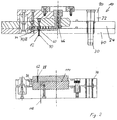
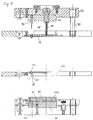
- FIGS. 1 to 4 show views of a subject injection molding tool 10 in a particularly preferred embodiment in various stages of the process.
- the FIG. 1 shows a view of a subject injection molding tool 10 in a particularly preferred embodiment in the closed state
- the FIG. 2 shows a view of the injection mold 10 from Fig. 1 in a first partially opened state
- the Fig. 3 shows the injection mold 10 in a second partially opened state
- Fig. 4 shows the injection mold 10 in a total open position.
- essential elements of an external actuator 11 are shown.
- the aim of the subject injection molding tool 10 is the production of a larger number of pin-shaped End products, so-called benefits 12, separating from their carrier system 16 and applying them in a single cycle.
- Fig. 1 shows this injection molding tool 10 in the closed position in a full section with horizontally aligned center axis 18 and parts of an external actuator 11. All movements of the following components of the injection molding 10 carried at least approximately translationally and parallel to this center axis 18th
- the injection molding tool 10 itself is suitable for use in conventional injection molding machines and in the present embodiment comprises three essential components.
- the first assembly is formed by a base plate assembly 20 which is fixedly connected to an injection molding machine, not shown here.
- This base plate assembly 20 includes a base plate 22 and a skin plate 24.
- the base plate 22 provides the interface between the injection mold 10 and the static side of the injection molding machine and receives at its opposite end face 28, the skin plate 24.
- This skin plate 24 is flat against the base plate 22. While the base plate 22 is fixedly connected to the injection molding machine, the skin plate 24 is translationally guided on guide columns 30, which are mounted parallel to the center axis 18 on the base plate 22. These guide columns 30 guarantee an exact movement of the skin plate 24 relative to the base plate 22.
- the base plate 22 may, as in Fig. 1 seen also be designed in several parts, but this constructive features are relevant, for the function this is not relevant.
- the sprue 34 is advantageous - as in the Fig. 1 to 3 shown - arranged coaxially to the center axis 18. It is formed centrally in a sprue bush, which is guided both by the base plate 22 and by the skin plate 24.
- the sprue 34 is in surface contact with a center plate 40 as part of a second assembly, whereby a first separation surface 42 is defined.
- the center plate 40 may be guided separately, in this advantageous embodiment, it is guided by holes on the base plate 22 analogous to the skin plate 24 on the guide columns 30 and parallel to the center axis 18 slidably, whereby an exact alignment of the center plate 40 is ensured to the skin plate 24.
- the center plate 40 and the skin plate 24 together form a fur cavity 44 into which the sprue 34 opens.
- This fur cavity 44 together with the runner 34, the mold for the support system 16 of the molding to be molded 50, comprising a sprue 46 and a flat, rotationally symmetrical skin 48, ready.
- the Fellkavtician 44 is flat and thin-walled in the region of the first separation surface 42, and serves to distribute the injection molding to be introduced.
- the in the Fig. 1 and 2 in the middle of the center plate 40 is in the Fig. 3 and 4 shown in off, and thus open, state.
- the center plate 40 is clamped between the base plate assembly 20, with which it defines the first separation surface 42, and a utility plate assembly 56 as a third assembly, with which it forms a second separation surface 58.
- each plate 22, 24, 40, 80, 82 at least a pair of so-called centering cones 59 are parallel to the axis and introduced from one end face to the opposite end face continuously.
- each centering 59 engages with each end face in the adjacent Zentrierkonen 59 and thereby causes a fine centering, which belong to each other Zentrierkonen 59 in a precise alignment.
- the centering cones 59 do not act in contrast to the guide columns 30 over the entire stroke, but take only an additional gene positioning in the last stroke section just before the mutual contact of each mutually facing faces of adjacent plates 22, 24, 40, 80, 82 of the injection mold 10, and increase the flight accuracy of the same additional.
- the benefit plate assembly 56 has in the direction of the second parting surface 58 molded hollow molds corresponding in the present case a blind hole with spherical bottom, identical to each other in shape and dimension and parallel to the center axis 18 and arranged systematically to this.
- These hollow benefit molds open into the second parting surface 58 and are limited by the center plate 40.
- the center plate 40 has corresponding hollow shapes with congruent contours as matching counter-forms, in the present case, however, these hollow shapes are not specially designed, but are reduced in their depth to zero and are thus formed by a common plane surface, which with the second parting surface 58 coincides when closed.
- each benefit cavity mold is limited at its open end by a respective portion of the planar surface, hereinafter referred to as a support surface 60.
- a support surface 60 a respective portion of the planar surface, hereinafter referred to as a support surface 60.
- each Nutzhohlform in conjunction with one of the support surfaces 60 is aorkavtician 62, as in the Fig. 1 to 4 and detailed in Fig. 5 represented, for the production of the benefits 12 formed.
- These utility cavities 62 each adjoin an inflow orifice 68, which opens centrally into its respective support surface 60 and reduces it to a circular area.
- This annular support surface 60 of each doublkavtician 62 has the task in the demolding process, at the beginning of which it also accomplishes a separation of the associated benefit 12 from the common coat 48, the benefit 12 to support its useful end face 70 sufficiently so that a certain surface pressure is not exceeded ,
- the Theieskavticianen 62 are each aligned parallel to each other in the present case and are identical in shape and dimension, but this is not necessarily a prerequisite for the present invention.
- Each Particularkavtician 62 is in the region of its support surface 60 via the associated inflow 68 with the opposite side of the center plate 40 and the Fellkavmaschine located there 44 connected via an inlet sink 74.
- the inflow orifices 68 are each arranged concentrically to theirprimarilykavtician 62.
- the inlet sinks 74 are aligned axially parallel to the center axis 18 and taper in the direction of the inflow openings 68 over the greater part of their depth.
- the conical shape of Zulaufsenken 74 causes sprayed material, which is distributed starting from the runner 34 in the area of the skin cavity 44, flows as evenly and with the lowest possible resistance in the inlet wells 74, at the inflow 68 out of the fur cavity 44 off and in theendedkavmaschineen 62 can occur.
- the benefit plate assembly 56 is disposed on the movable part of the injection molding machine, is linearly moved by this, and requires no further positive guidance. As in the Fig. 1 to 3 shown, but bushes 76 are analogous to the center plate 40, which is a retraction of the guide columns 30 when closing the Allow injection mold 10 before reaching the end position, with the aim of an exact alignment of all moving elements to each other.
- the benefit plate assembly 56 is substantially in two parts and consists of a face plate 80 as a base body, which is attached to the moving part of the injection molding machine, and a shank plate 82. This shank plate 82 is supported by the end plate 80 and relative to her linear and parallel to the center axis 18 slidably arranged.
- An intermediate separation plane 84 is also aligned parallel to the first and second separation surfaces 42, 58 and thereby spaced from the second separation surface 58 such that the non-muzzle head portions 86 of the2-kavticianen 62 are formed in the Stirnformplatte 80.
- the second separating surface 58 could have a plurality of partial surfaces which do not necessarily have to lie in a common plane, as in the present case.
- the face plate 80 is also shown in several parts analogous to the base plate 22, however is the multi-part is only constructive, a one-piece design would be conceivable.
- Fig. 5 shows that the core 90 in the particularly critical region of the inflow orifice 68 approaches very close to its contour, and only a very small, circular inflow cross section 92 remains, can flow through which sprayed material from the fur cavity 44 in the Brunswickkavtician 62.
- the finished injection molding 50 thus has at these points in each case only a very small material thickness, whereby a predetermined breaking point 94 between 12 benefits and fur 48 is formed automatically.
- the pin-shaped core 90 may be formed thicker in the Fellkavtician 44, which benefits its stability, and secondly, the spray can flow more easily and distribute more evenly. Since the core 90 in the region of the inlet sink 74 with its longitudinal contour that of the inlet sink 74 while maintaining a minimum distance follows, a kind of funnel with inner core is formed therebetween, through which the supplied spray material is superimposed with a swirl-like movement, and thus can flow more uniformly into the respectiveprimarily chronologicalkavtician 62. As a result, a smoother, more homogeneous filling process is achieved and at the same time reduced uneven radial loads on the core 90.
- the remaining inflow cross section 92 is positioned coaxially with the core 90 and small in relation to the surrounding support surface 60.
- the dimension of its inflow cross section 92 must be sufficiently large to ensure the necessary flow of spray material with a corresponding resistance.
- the cross section of the support surface 60 is a multiple of the inflow cross section 92, in the present case, the support surface 60 is at least 5 times, preferably more than 10 times the inflow cross section 92, which forms a circular ring of about 0.1 mm here.
- the circular ring can also have a different size.
- the inflow cross section 92 defines the position of the predetermined breaking point 94 for the benefit 12, it is therefore desirable to keep this as low as possible.
- the plane of the predetermined breaking point 94 coincides with the second separating surface 58.
- a hollow knob 98 shown as Anformung the fur 48 are not necessary in every case, however, they support the mixing process due to their practically congruent cross-section to the feed wells 74. Further, they increase the sum of the surfaces of the skin cavity 44 in the direction of movement of the center plate 40, which has an increasing effect on the liability of the injected fur 48 in the fur cavity 44 and is desirable in the present case.
- the hollow knobs 98 are formed in annular gaps 100, which are part of the fur cavity 44 and are conveniently formed on the circumference of the core 90 by the necessary, continuous fur holes 99 are designed for the cores 90 in the skin plate 24 correspondingly larger, so each a cavity in Form of a circular ring cylinder, and thus the annular gap 100, is formed.
- These annular gaps 100 are limited by the base plate 22 on the front side.
- the annular gaps 100 are likewise filled and thereby formed simultaneously with the spraying of the skin 48.
- sufficient resistance between the skin 48 and the mold in the skin plate 24 is given.
- instead of the annular gaps 100 instead of the annular gaps 100, alternative, purpose-same expressions are also conceivable.
- the core carrier 102 is part of the base plate 22 carries all cores 90, which are inserted from its rear side through fur holes 99 in the skin plate 24 and fixed by means of threaded pins to internal threads in the core carrier 102.
- the core carrier 102 can be easily removed and replaced without the entire base plate 22 has to be removed during replacement of the injection molding machine.
- for disassembly of the core support 102 directly or indirectly actuated connecting screws due to practical requirements may be arranged differently than in the Fig. 1-4 shown.
- a closing valve 108 is mounted with a poppet 110, which extends through the center plate 40 in the surface region of the Fellkavtician 44.
- a vacuum channel 112 a vacuum source, not shown, through which the existing in the cavities 44, 62 of the closed injection mold 10 air can be sucked off, so as to be able to provide a lower pressure level, ideally vacuum. This facilitates the injection process and significantly improves the splash result.
- the closing valve 108 is in the open position, which represents its basic position in that the plunger 110 protrudes spring-supported in the fur cavity 44 and the air contained is ausbringbar.
- the plunger 110 has the task of sealing the closing valve 108 at its seat relative to the fur cavity 44 and withstand the pressure in the fur cavity 44. Therefore, the pommel 110 opens only in the direction of the fur cavity. Since the plunger 110 is aligned approximately flush with the sprue 34, inflowing spray material hits the plate of the plunger 110 and automatically closes the closing valve 108.
- Fig. 6 shows a hollow shape-side plan view of the skin plate 24.
- the mouth of the sprue 34 is shown centrally and the area of the fur coat 44, which has a circular boundary in the present case.
- another shape, such as a square boundary would be possible, but a circular design ensures a uniform filling during injection.
- the fur holes 99 present in the skin plate 44 are visible, through which the cores 90 penetrate into the fur cavities 44 from the rear side while maintaining the annular gap 100.
- the arrangement and number of fur holes 99 corresponds to that of theendedkavmaschineen 62nd
- While the utility plate assembly 56 is actuated entirely by the injection molding machine, the actuation of the center plate 40 by an external actuator 11.
- This has actuators, in the present case center plate cylinder 122, which act on extensions of the center plate 40 in the edge region.
- the skin plate 24 is by a resistance device 124, which in the present case - as in Fig. 6 visible - is realized via spring-actuated balls, held up to a certain limit force in loaded system on the base plate assembly 20. It is only offset from a certain stroke by so-called stroke limiter 128, which are firmly connected to the center plate 40, in translation, and so lifted from the base plate assembly 20.
- the center plate cylinders 122 other pneumatic, hydraulic, electrical or electromechanical drives are conceivable.
- the movement between the end plate 80 and the shank plate 82 can be done hydraulically, mechanically or by compressed air as soon as no contact force by the injection molding machine 10 acts more.
- the method using the aforementioned injection molding tool 10 allows the production of the benefits 12 as well as their separation from the remaining injection molding 50 as well as the application of the benefits 12 in a single cycle.
- the injection mold 10 is closed, the utility plate assembly 56 and the base plate assembly 20 abut the center plate 40 in the first and second separation surfaces 42 and 58.
- the contact pressure in the first and second parting surfaces 42, 58 is applied to the utility plate assembly 56 by the injection molding machine, and the center plate cylinders 122 are preferably powerless. However, they may also be under force to push the center plate 40 against the base plate assembly 20.
- the trapped air is then sucked out of the cavities 44, 62 in the best possible manner via the closing valve 108 through the vacuum channel 112 in order to achieve at least a vacuum-like state. This process could be omitted, if that Injection mold 10 is operated in a vacuum or low pressure environment.
- sprayed material is introduced through the sprue channel 34, which flows at high speed into the furcavity 44 and strikes the plate of the closure valve 108 there, whereby the centrically impinging sprayed material flow is deflected in radial directions.
- the dynamic pressure occurring, which forms due to the inflow when hitting the Spritzgutstroms on the poppet 110, a closing of the closing valve 108th
- the first and the previous course of the second process step take place with partial overlapping in order to keep the cycle time as short as possible.
- the pressure on the closing valve 108 remains upright due to the incoming spray material. This flows through the furcave 44 to the inlet sinks 74 and enters through the inflow openings 68 in the Brunswickkavticianen 62 a. If the useful cavities 62 and the fur cavities 44 are filled, then the volume flow approaches zero, but the injection material is placed under high pressure by the injection molding machine, and the closing valve 108 remains closed. As soon as the sprayed material has reached a certain strength by the hardening or hardening process, and the sprayed part 50 is formed, the pressure drops, but the closing valve 108 remains closed, since movement is hindered by the now solid spraying material.
- the demolding After curing of the injection molding for injection molding 50 begins with a third process step, the demolding.
- the end mold plate 80 is moved by the movable side of the injection molding machine by a predetermined stroke, the stem mold plate 82 remains due to the adhesion of the molding 50 and the power plate assembly 56 opens, so that the gap space 114 is formed.
- the injection mold 10 is relieved.
- the injection molding 50 is still enclosed in the outwardly closed injection molding tool 10, only the head portions 116 of the benefit 12 collar freely in the gap 114.
- a fourth method step the utility plate assembly 56 is retracted and the tool in the second separation surface 58 is separated.
- the shank mold plates 82 with their shaft cavity sections lift off the benefits 12 so that they are exposed.
- the compressed air in the gap 114 assists the molding process of the benefits 12.
- the stroke is matched to the geometry of the benefits 12 such that the benefits 12 are not spatially impeded in the subsequent process step.
- Fig. 2 shows the final state after this process step.
- the center plate 40 by a defined stroke, which is at least the length each core 90 in the shaft of a benefit 12 corresponds, moved translationally, and thereby lifted in the first parting surface 42 of the skin plate 24.
- the center plate 40 acts on its support surfaces 60 due to the existing positive fit on the free end facing away from the annular end faces of the benefits 12 and rips them in the inflow 68, due to the existing breaking point 94 there, from the common coat 48 by the tensile strength of Springs 50 is exceeded.
- the benefits 12 are deducted from the cores 90 thanks to the corresponding stroke of the center plate 40. Once the retention of the cores 90 has been lost, the benefits 12 fall downwardly due to gravity and may be collected by a device, not shown.
- center plate 40 The movement of the center plate 40 is carried out according to the present case Fig. 1 by center plate cylinder 122, which are mounted symmetrically outside the center plate 40.
- center plate cylinder 122 which are mounted symmetrically outside the center plate 40.
- other actuators would be conceivable, but it would also be possible to realize a positive driving with the utility plate assembly 56.
- the guide columns 30 are too short to guide the center plate 40 over the entire stroke, this forced guidance must be taken over by the center plate cylinders 122 or other devices, not shown.
- the coat 48 In order for the benefit 12 to be able to be torn off at all, when the center plate 40 is lifted off, the coat 48 must detach from its surface portion at the fur cavity 44 and remain in that of the hide plate 24.
- the restraining force consisting of the sum of the frictional and adhesive forces acting in the direction of movement between the skin 48 and the skin plate 24 and the cores 90, in the area of the skin cavity 44 must be greater than the sum of the opposing forces comprising the force for the tearing off the benefit 12 plus the adhesion forces between hide 48 and center plate 40 plus the frictional forces of the benefits 12 on respective sections of the cores 90.
- annular gaps 110 are formed in the hollow shape of the skin plate 24, which form projections on spraying of the skin 48 on the side remote from the use, in particular hollow studs 98, and the formation of larger friction surfaces is achieved.
- the hollow knobs 98 are co-formed concentrically with the inflow orifices 68, which minimizes any shearing forces that may be exerted on the fur 48 and that the fur 48 is capable of providing sufficient resistance.
- the skin plate 24 is preferably formed as a self-contained unit and is guided on sockets 76 by the guide columns 30 over the entire necessary stroke.
- the translational movement is carried out in alignment with that of the center plate 40.
- the lifting operation of the skin plate 24 takes place by a forced driving via stroke limiter 128 on the center plate 40 and is pulled by these quasi.
- the center plate 40 covered a certain way the skin plate 24 is taken by the stroke limiter and moved in translation by a certain way.
- the maximum distance between the center plate 40 and skin plate 24 is defined.
- this forced operation is maintained over the entire stroke.
- the skin 48 located in the skin plate 24 is peeled off from the cores 90 fixed in the base plate 22 and at the same time the gate 46 connected to the skin 48 is formed from the runner 34.
- This condition is in FIG. 4 shown. Since the resistance at the cores 90 is eliminated, the fur 48 with the sprue 46 can be easily removed from the hollow shape of the skin plate 24. This can be done manually or by means of an automated manipulator. Of course, an independent drive for the skin plate 24 would alternatively be conceivable.
- the injection molding tool 10 is in the fully open position and all its movable components are separated from each other, but aligned with each other.
- the center plate 40 is first moved back in the direction of the base plate assembly 20 by means of the center plate cylinder 122.
- the return movement of the center plate 40 may preferably be effected by the center plate cylinder 122, but also alternative electrical, mechanical or pneumatic drive options would be conceivable.
- the return movement of the utility plate assembly 56 by means of the movable part of the injection molding machine until it rests against the middle plate 40 in the second separation surface 58.
- the benefit plate assembly 56 is moved back towards the base plate assembly 20 by the moving part of the injection molding machine, thereby entering its return path on the middle plate 40 in the second parting surface 58 in abutment, wherein in a preferred embodiment, first, the shank plate 82 in With completed full-scale investment in the area of the second separation surface 58, the positive drive of the center plate 40 takes place.
- the center plate cylinders 122 must be movable without power, and must not counteract the movement. In this case, therefore, single-acting cylinders are sufficient.
- an independent process of the center plate 40 in the closed position could be carried out by the center plate cylinders 122 are executed double-acting and accomplish the return stroke. Other mechanisms are conceivable.
- the skin plate 24 comes into abutment in the first parting surface 42, so that the fur cavity 44 is closed, and due to a Zwangsmitglazed the fur plate 24 moves together with the center plate 40 and plate assembly 56 back to the closed position until a full-surface Attachment is given to the base plate 22.
- the cores 90 penetrate through the corresponding fur holes 99 of the skin plate 24 in the closed skin cavity 44 and theologikavticianen 62 into it. So that easily is possible, a very precise guidance relative to each other is necessary, and the sensitive cores 90 must not be deformed.
- the injection molding tool 10 is now completely closed and the individual components are held in contact with each other by a predetermined closing force of the injection molding machine.
- the injection mold 10 is now back in the starting position and ready for the next cycle.
Landscapes
- Engineering & Computer Science (AREA)
- Manufacturing & Machinery (AREA)
- Mechanical Engineering (AREA)
- Moulds For Moulding Plastics Or The Like (AREA)
- Injection Moulding Of Plastics Or The Like (AREA)
Claims (16)
- Moule d'injection avec un arrangement de plaques de base (20), qui présente un canal de coulée (34) prévu pour la connexion à une machine de moulage par injection, une plaque centrale (40) qui - dans l'état fermé du moule d'injection (10) - est ajustée contre l'arrangement de plaques de base (20) dans une première zone de séparation (42) et forme avec cet arrangement de plaques de base (20) une cavité de peau (44) connectée au canal de coulée (34), et un arrangement de plaques de moulage (56) qui - dans l'état fermé du moule d'injection (10) - est ajusté contre la plaque centrale (40) dans une deuxième zone de séparation (58), délimite avec cette plaque centrale (40) un nombre de cavités de moulage (62) et est prévu pour être arrangé sur la partie mobile de la machine de moulage par injection, les cavités de moulage (62) étant connectées à la cavité de peau (44) chacune au moyen d'une bouche d'entrée (68) formée sur la plaque centrale (40) pour être remplies avec du matériau d'injection, et chacune étant délimitée au moyen d'une surface de support (60), qui est formée sur la plaque centrale (40) et s'étend de façon annulaire autour de la bouche d'entrée (68), l'arrangement de plaques de moulage (56) consistant en au moins une plaque de moulage frontale (80) et une plaque de moulage de tige (82), cette dernière- dans l'état fermé du moule d'injection (10) - étant ajustée d'un côté contre la plaque centrale (40) dans la deuxième zone de séparation (58) et d'un autre côté contre la plaque de moulage frontale (80), caractérisé en ce que les surfaces de support (60) supportent les moulages (12) créés de telle façon que lors de l'ouverture du moule d'injection (10) dans la première zone de séparation (42) - après que l'arrangement de plaques de moulage (56) est ramené et le moule d'injection (10) est séparé dans la deuxième zone de séparation (58), la plaque de moulage de tige (82) se décollant avec ses parties de cavité de tige des moulages (12), de telle sorte que ces derniers sont libres - les moulages (12) se séparent de la peau (48) créée dans la cavité de peau (44).
- Moule d'injection selon la revendication 1, caractérisé en ce que, dans l'arrangement de plaques de base (20), pour chaque cavité de moulage (62) un noyau (90) en forme de tige - en particulier présentant une section transversale circulaire - est fixé et est en saillie librement, lequel se prolonge à travers la bouche d'entrée (68) dans la cavité de moulage (62) concernée.
- Moule d'injection selon la revendication 2, caractérisé en ce qu'une section transversale d'entrée (92) de forme annulaire, qui est positionnée coaxialement par rapport au noyau (90), est formée entre le noyau (90) et la bouche d'entrée (68).
- Moule d'injection selon la revendication 3, caractérisé en ce que la surface de support (60) est au moins 5 fois, préférablement plus de 10 fois, la section transversale d'entrée (92).
- Moule d'injection selon l'une des revendications 1-4, caractérisé en ce que la cavité de peau (44) présente une partie de cavité plane, dans laquelle le canal de coulée (34) débouche, et de laquelle des fraisures d'entrée (74) appartenant à chaque bouche d'entrée (68) sont formées dans la plaque centrale (40), lesquelles traversent la section transversale complète de la plaque centrale (40) et se rétrécissent dans la direction des bouches d'entrée (68) respectives.
- Moule d'injection selon l'une des revendications 1 à 5, caractérisé en ce que la plaque de moulage frontale (80) est prévue pour être arrangée sur la partie mobile de la machine de moulage par injection, et la plaque de moulage de tige (82) est positionnée de façon ajustable dans la limite d'un déplacement prédéterminé sur la plaque de moulage frontale (80) et est préférablement précontrainte dans la direction de la plaque centrale (40).
- Moule d'injection selon la revendication 6, caractérisé en ce que la plaque de moulage frontale (80) est ajustée contre la plaque de moulage de tige (82) et, lors de l'ouverture du moule d'injection (10), un espace de séparation (114) qui est sinon au moins approximativement fermé se forme entre la plaque de moulage frontale (80) et la plaque de moulage de tige (82).
- Moule d'injection selon la revendication 7, caractérisé en ce qu'un canal de gaz comprimé (118) prévu pour être connecté à une source d'air comprimé conduit préférablement à travers la plaque de moulage frontale (80) dans l'espace de séparation (114).
- Moule d'injection selon l'une des revendications 1 à 8, caractérisé en ce qu'une région frontale des cavités de moulage (62) opposée à la surface de support (60) est formée sur la plaque de moulage frontale (80) et une région de tige (88) des cavités de moulage (62) adjacente à cette région frontale est formée dans la plaque de moulage de tige (82).
- Moule d'injection selon l'une des revendications 1 à 9, caractérisé en ce que la plaque centrale (40) est connectée à un entraînement qui est prévu pour séparer la plaque centrale (40) avec les moulages (12) de la peau (48), et si nécessaire le déplacement de la plaque centrale (40) est choisi de telle sorte qu'une séparation entre les moulages (12) et le noyau (90) est assuré.
- Moule d'injection selon l'une des revendications 1 à 10, caractérisé en ce qu'un canal de dépression (112) débouchant dans la cavité de peau (44) est présent, lequel est prévu pour être connecté à une source de dépression.
- Moule d'injection selon la revendication 11, caractérisé en ce que le canal de dépression (112) contient une valve de fermeture à ouverture automatique (108) disposée à l'embouchure dudit canal (112) dans la cavité de peau (44) et disposée en face du canal de coulée (34) et qui, lors de l'entrée du matériau d'injection par le canal de coulée (34), est amenée en position de fermeture par ce dit matériau d'injection.
- Moule d'injection selon l'une des revendications 1 à 12, caractérisé en ce que la cavité de peau (44) dans l'arrangement de plaques de base (20) présente des formations concaves ou convexes avec de façon avantageuse majoritairement des régions de surface axialement parallèles, et ainsi offre une résistance définie à un éventuel retrait de la peau (48).
- Moule d'injection selon la revendication 13, caractérisé en ce que la résistance définie dans la direction du mouvement d'ouverture et de fermeture du moule d'injection (10) est au moins aussi grande que la somme des forces d'adhésion de la région partielle de la cavité de peau (44) dans la plaque centrale (40) plus les forces nécessaires pour arracher les moulages (12).
- Moule d'injection selon les revendications 2 et 13 ou selon les revendications 2 et 14, caractérisé en ce que les formations sont formées par des fentes annulaires (24) concentriques, dont les diamètres intérieurs sont déterminés par les noyaux (90) et les diamètres extérieurs sont déterminés par des perçages de peau (99) surdimensionnés, qui traversent et s'étendent coaxialement par rapport aux noyaux (90).
- Procédé de moulage par injection d'un nombre de moulages (12) dans un nombre de cavités de moulage (62), présentant les étapes suivantes:- préparation d'un moule d'injection (10) selon l'une des revendications 2 à 15 dans un état fermé;- injection de matériau d'injection par le canal de coulée (34) dans la cavité de peau (44) et dans toutes les cavités de moulage (62) pour former une pièce moulée par injection (50) d'un seul tenant avec une coulée (46), une peau (48) créée dans la cavité de peau (44) et des moulages (12) créés dans les cavités de moulage (62);- maintien du moule d'injection (10) pendant un certain temps en contrôlant la température jusqu'à atteindre un état dimensionnellement stable de la pièce moulée par injection (50) obtenue de cette façon;- ouverture du moule d'injection (10) dans la première zone de séparation (42) d'une distance de déplacement prédéterminée, une séparation des moulages (12) de la peau (48) ayant lieu dans le plan de la surface de support (60) au début de ce déplacement, dans lequellors de l'ouverture du moule d'injection (10), la plaque centrale (40) est soulevée d'une distance de déplacement prédéterminée, la distance de déplacement étant choisie de telle sorte que l'extraction des moulages (12) des noyaux (90) est assurée,
et dans lequel l'ouverture du moule d'injection (10) a lieu en deux étapes, l'arrangement de plaques de moulage (56) étant soulevé dans la première étape dans la deuxième zone de séparation (58), ce qui provoque l'ouverture des cavités de moulage (62), et la plaque centrale (40) étant soulevée dans la deuxième étape dans la première zone de séparation (42), les moulages (12) étant séparés de la peau (48).
Priority Applications (4)
| Application Number | Priority Date | Filing Date | Title |
|---|---|---|---|
| SI200931520A SI2269799T1 (sl) | 2009-07-01 | 2009-07-01 | Naprava za izdelavo končnih proizvodov v obliki čepov z injekcijskim litjem |
| EP09008607.5A EP2269799B1 (fr) | 2009-07-01 | 2009-07-01 | Dispositif de fabrication de produits finis en forme de crayon par moulage par injection |
| ES09008607.5T ES2593833T3 (es) | 2009-07-01 | 2009-07-01 | Dispositivo para la fabricación de productos finales en forma de clavija mediante moldeo por inyección |
| US12/827,559 US8313685B2 (en) | 2009-07-01 | 2010-06-30 | Device for producing pin-shaped end products by the injection-molding process |
Applications Claiming Priority (1)
| Application Number | Priority Date | Filing Date | Title |
|---|---|---|---|
| EP09008607.5A EP2269799B1 (fr) | 2009-07-01 | 2009-07-01 | Dispositif de fabrication de produits finis en forme de crayon par moulage par injection |
Publications (2)
| Publication Number | Publication Date |
|---|---|
| EP2269799A1 EP2269799A1 (fr) | 2011-01-05 |
| EP2269799B1 true EP2269799B1 (fr) | 2016-06-29 |
Family
ID=41212223
Family Applications (1)
| Application Number | Title | Priority Date | Filing Date |
|---|---|---|---|
| EP09008607.5A Not-in-force EP2269799B1 (fr) | 2009-07-01 | 2009-07-01 | Dispositif de fabrication de produits finis en forme de crayon par moulage par injection |
Country Status (4)
| Country | Link |
|---|---|
| US (1) | US8313685B2 (fr) |
| EP (1) | EP2269799B1 (fr) |
| ES (1) | ES2593833T3 (fr) |
| SI (1) | SI2269799T1 (fr) |
Families Citing this family (2)
| Publication number | Priority date | Publication date | Assignee | Title |
|---|---|---|---|---|
| US8293572B2 (en) * | 2011-01-20 | 2012-10-23 | ADL Engineering Inc. | Injection molding system and method of chip package |
| CN111688119B (zh) * | 2020-05-14 | 2022-02-18 | 佛山市晫尔模具有限公司 | 一种注塑模具结构 |
Family Cites Families (12)
| Publication number | Priority date | Publication date | Assignee | Title |
|---|---|---|---|---|
| FR1136064A (fr) | 1955-12-08 | 1957-05-09 | Seringues Ind Soc D Expl Des | Bouchon pour bouteilles, flacons et autres récipients |
| US3357057A (en) * | 1965-10-15 | 1967-12-12 | Harry R Bucy | Mold for pressure injected material |
| US3575233A (en) * | 1968-10-07 | 1971-04-20 | Joachim Mahle | Diecasting mold |
| JPS549119B1 (fr) | 1970-09-16 | 1979-04-21 | ||
| JPS56119254A (en) * | 1980-02-25 | 1981-09-18 | Takeda Chemical Industries Ltd | Rubber stopper for vial |
| JPS5747637A (en) | 1980-09-06 | 1982-03-18 | Daikyo Gomme Seikou:Kk | Manufacture of laminate rubber stopper |
| DE3346351A1 (de) | 1983-12-22 | 1985-07-11 | Pharma-Gummi Wimmer West Gmbh, 5180 Eschweiler | Pharmazeutischer stopfen, kolben od. dgl. und verfahren zum herstellen von pharmazeutischen stopfen, kolben od. dgl. |
| US5484566A (en) | 1994-03-07 | 1996-01-16 | Wheaton Inc. | Method of manufacture of a partially laminated rubber closure |
| JP3371795B2 (ja) | 1998-03-11 | 2003-01-27 | 住友電装株式会社 | 金型構造 |
| JP2000202837A (ja) | 1999-01-11 | 2000-07-25 | Daikyo Seiko Ltd | ラミネ―トゴム栓の製造方法及びラミネ―トゴム栓 |
| US6841114B2 (en) * | 2001-03-28 | 2005-01-11 | Mitsubishi Cable Industries, Ltd. | Molding method and apparatus for resin long body |
| DE10122959A1 (de) | 2001-05-11 | 2002-11-21 | West Pharm Serv Drug Res Ltd | Pharmazeutischer Spritzenkolben sowie Verfahren und Vorrichtung zu dessen Herstellung |
-
2009
- 2009-07-01 EP EP09008607.5A patent/EP2269799B1/fr not_active Not-in-force
- 2009-07-01 SI SI200931520A patent/SI2269799T1/sl unknown
- 2009-07-01 ES ES09008607.5T patent/ES2593833T3/es active Active
-
2010
- 2010-06-30 US US12/827,559 patent/US8313685B2/en active Active
Also Published As
| Publication number | Publication date |
|---|---|
| US20110001269A1 (en) | 2011-01-06 |
| SI2269799T1 (sl) | 2016-10-28 |
| ES2593833T3 (es) | 2016-12-13 |
| US8313685B2 (en) | 2012-11-20 |
| EP2269799A1 (fr) | 2011-01-05 |
Similar Documents
| Publication | Publication Date | Title |
|---|---|---|
| DE3228743C2 (de) | Mehrfachspritzgießform zum gleichzeitigen Herstellen mehrerer Formlinge | |
| DE2615177C3 (de) | Vorrichtung zum Herstellen von austriebfreien Formteilen aus einer Formmasse aus Elastomeren oder aus vernetzbaren bzw. härtbaren Kunststoffen | |
| EP2358513B1 (fr) | Système de post-traitement et de transfert de préformes | |
| DE1479178B1 (de) | Vorrichtung zur Herstellung hohler Gegenstaende aus thermoplastischem Kunststoff | |
| EP0824057B1 (fr) | Procédé et dispositif pour fabriquer des articles moulés par injection en matière plastique | |
| DE1084908B (de) | Verfahren und Vorrichtung zum Herstellen von Flaschen aus thermoplastischem Kunststoff nach der Methode des Aufblasens eines hohlen durch Spritzgiessen hergestellten Vorformlings | |
| DD139813A5 (de) | Form,insbesondere spritzgiessform,zum herstellen von fo | |
| EP0315586A1 (fr) | Moule d'injection à canal chauffé pour la fabrication de seringues à jeter et similaire | |
| DE102014012416B3 (de) | WERKZEUG ZUM SPITZGIEßEN VON BAUTEILEN UND HERSTELLVERFAHREN FÜR SPRITZGIEßTEILE | |
| DE102014019706B4 (de) | Spritzgießwerkzeug und Verfahren zur spannungsfreien Entformung eines Angusssystems an dem Spritzgießwerkzeug | |
| EP3186063B1 (fr) | Système de traitement ultérieur de préformes fabriquées par moulage par injection | |
| EP1712341B1 (fr) | Buse d'injection avec deux orifices de sortie | |
| DE102014101107A1 (de) | Gießform | |
| WO2021121977A1 (fr) | Outil et procédé de moulage par injection d'une pièce moulée par injection dans un outil | |
| EP3678777B1 (fr) | Procédé de fabrication d'une bande de récipients | |
| EP2269799A1 (fr) | Dispositif de fabrication de produits finis en forme de crayon utilisant un procédé de moulage par injection | |
| DE10355018A1 (de) | Formnestaufbau | |
| DE1479245A1 (de) | Verfahren zur Fabrikation von duennwandigen Behaeltern aus thermoplastischem Material und Einrichtung zu seiner Verwirklichung | |
| DE102012102266A1 (de) | Spritzgießwerkzeugplatte sowie Spritzgießwerkzeug mit einer solchen | |
| EP3620287A2 (fr) | Élément de réception | |
| DE102019125252A1 (de) | Spritzgießvorrichtung, Verfahren zum Spritzgießen von Mehrkomponenten-Teilen, Verwendung eines Platzhalterelements sowie Computerprogramm und computerlesbares Medium | |
| DE102005027296B3 (de) | Vorrichtung zum Herstellen eines Formteils aus Pulver | |
| EP1954468A1 (fr) | Procede et systeme pour post-traitement de preformes | |
| EP0853812B1 (fr) | Procede et dispositif destine au montage final d'un clavier d'ordinateur | |
| DE10154447B4 (de) | Kunststoffspritzverfahren zum Spritzen von einseitig offenen Hohlkörpern als Formteile |
Legal Events
| Date | Code | Title | Description |
|---|---|---|---|
| PUAI | Public reference made under article 153(3) epc to a published international application that has entered the european phase |
Free format text: ORIGINAL CODE: 0009012 |
|
| AK | Designated contracting states |
Kind code of ref document: A1 Designated state(s): AT BE BG CH CY CZ DE DK EE ES FI FR GB GR HR HU IE IS IT LI LT LU LV MC MK MT NL NO PL PT RO SE SI SK SM TR |
|
| AX | Request for extension of the european patent |
Extension state: AL BA RS |
|
| 17P | Request for examination filed |
Effective date: 20110603 |
|
| 17Q | First examination report despatched |
Effective date: 20121212 |
|
| GRAP | Despatch of communication of intention to grant a patent |
Free format text: ORIGINAL CODE: EPIDOSNIGR1 |
|
| INTG | Intention to grant announced |
Effective date: 20160114 |
|
| GRAS | Grant fee paid |
Free format text: ORIGINAL CODE: EPIDOSNIGR3 |
|
| GRAA | (expected) grant |
Free format text: ORIGINAL CODE: 0009210 |
|
| AK | Designated contracting states |
Kind code of ref document: B1 Designated state(s): AT BE BG CH CY CZ DE DK EE ES FI FR GB GR HR HU IE IS IT LI LT LU LV MC MK MT NL NO PL PT RO SE SI SK SM TR |
|
| REG | Reference to a national code |
Ref country code: GB Ref legal event code: FG4D Free format text: NOT ENGLISH |
|
| REG | Reference to a national code |
Ref country code: CH Ref legal event code: EP |
|
| REG | Reference to a national code |
Ref country code: AT Ref legal event code: REF Ref document number: 808731 Country of ref document: AT Kind code of ref document: T Effective date: 20160715 |
|
| REG | Reference to a national code |
Ref country code: IE Ref legal event code: FG4D Free format text: LANGUAGE OF EP DOCUMENT: GERMAN |
|
| REG | Reference to a national code |
Ref country code: DE Ref legal event code: R096 Ref document number: 502009012734 Country of ref document: DE |
|
| REG | Reference to a national code |
Ref country code: CH Ref legal event code: NV Representative=s name: PATENTANWAELTE SCHAAD, BALASS, MENZL AND PARTN, CH |
|
| REG | Reference to a national code |
Ref country code: FR Ref legal event code: PLFP Year of fee payment: 8 |
|
| REG | Reference to a national code |
Ref country code: LT Ref legal event code: MG4D |
|
| PG25 | Lapsed in a contracting state [announced via postgrant information from national office to epo] |
Ref country code: LT Free format text: LAPSE BECAUSE OF FAILURE TO SUBMIT A TRANSLATION OF THE DESCRIPTION OR TO PAY THE FEE WITHIN THE PRESCRIBED TIME-LIMIT Effective date: 20160629 Ref country code: NO Free format text: LAPSE BECAUSE OF FAILURE TO SUBMIT A TRANSLATION OF THE DESCRIPTION OR TO PAY THE FEE WITHIN THE PRESCRIBED TIME-LIMIT Effective date: 20160929 Ref country code: FI Free format text: LAPSE BECAUSE OF FAILURE TO SUBMIT A TRANSLATION OF THE DESCRIPTION OR TO PAY THE FEE WITHIN THE PRESCRIBED TIME-LIMIT Effective date: 20160629 |
|
| REG | Reference to a national code |
Ref country code: NL Ref legal event code: MP Effective date: 20160629 |
|
| PG25 | Lapsed in a contracting state [announced via postgrant information from national office to epo] |
Ref country code: LV Free format text: LAPSE BECAUSE OF FAILURE TO SUBMIT A TRANSLATION OF THE DESCRIPTION OR TO PAY THE FEE WITHIN THE PRESCRIBED TIME-LIMIT Effective date: 20160629 Ref country code: NL Free format text: LAPSE BECAUSE OF FAILURE TO SUBMIT A TRANSLATION OF THE DESCRIPTION OR TO PAY THE FEE WITHIN THE PRESCRIBED TIME-LIMIT Effective date: 20160629 Ref country code: GR Free format text: LAPSE BECAUSE OF FAILURE TO SUBMIT A TRANSLATION OF THE DESCRIPTION OR TO PAY THE FEE WITHIN THE PRESCRIBED TIME-LIMIT Effective date: 20160930 Ref country code: SE Free format text: LAPSE BECAUSE OF FAILURE TO SUBMIT A TRANSLATION OF THE DESCRIPTION OR TO PAY THE FEE WITHIN THE PRESCRIBED TIME-LIMIT Effective date: 20160629 Ref country code: HR Free format text: LAPSE BECAUSE OF FAILURE TO SUBMIT A TRANSLATION OF THE DESCRIPTION OR TO PAY THE FEE WITHIN THE PRESCRIBED TIME-LIMIT Effective date: 20160629 |
|
| REG | Reference to a national code |
Ref country code: ES Ref legal event code: FG2A Ref document number: 2593833 Country of ref document: ES Kind code of ref document: T3 Effective date: 20161213 |
|
| PG25 | Lapsed in a contracting state [announced via postgrant information from national office to epo] |
Ref country code: BE Free format text: LAPSE BECAUSE OF NON-PAYMENT OF DUE FEES Effective date: 20160731 |
|
| PG25 | Lapsed in a contracting state [announced via postgrant information from national office to epo] |
Ref country code: CZ Free format text: LAPSE BECAUSE OF FAILURE TO SUBMIT A TRANSLATION OF THE DESCRIPTION OR TO PAY THE FEE WITHIN THE PRESCRIBED TIME-LIMIT Effective date: 20160629 Ref country code: IT Free format text: LAPSE BECAUSE OF FAILURE TO SUBMIT A TRANSLATION OF THE DESCRIPTION OR TO PAY THE FEE WITHIN THE PRESCRIBED TIME-LIMIT Effective date: 20160629 Ref country code: EE Free format text: LAPSE BECAUSE OF FAILURE TO SUBMIT A TRANSLATION OF THE DESCRIPTION OR TO PAY THE FEE WITHIN THE PRESCRIBED TIME-LIMIT Effective date: 20160629 Ref country code: SK Free format text: LAPSE BECAUSE OF FAILURE TO SUBMIT A TRANSLATION OF THE DESCRIPTION OR TO PAY THE FEE WITHIN THE PRESCRIBED TIME-LIMIT Effective date: 20160629 Ref country code: IS Free format text: LAPSE BECAUSE OF FAILURE TO SUBMIT A TRANSLATION OF THE DESCRIPTION OR TO PAY THE FEE WITHIN THE PRESCRIBED TIME-LIMIT Effective date: 20161029 Ref country code: RO Free format text: LAPSE BECAUSE OF FAILURE TO SUBMIT A TRANSLATION OF THE DESCRIPTION OR TO PAY THE FEE WITHIN THE PRESCRIBED TIME-LIMIT Effective date: 20160629 |
|
| PG25 | Lapsed in a contracting state [announced via postgrant information from national office to epo] |
Ref country code: PL Free format text: LAPSE BECAUSE OF FAILURE TO SUBMIT A TRANSLATION OF THE DESCRIPTION OR TO PAY THE FEE WITHIN THE PRESCRIBED TIME-LIMIT Effective date: 20160629 Ref country code: SM Free format text: LAPSE BECAUSE OF FAILURE TO SUBMIT A TRANSLATION OF THE DESCRIPTION OR TO PAY THE FEE WITHIN THE PRESCRIBED TIME-LIMIT Effective date: 20160629 Ref country code: PT Free format text: LAPSE BECAUSE OF FAILURE TO SUBMIT A TRANSLATION OF THE DESCRIPTION OR TO PAY THE FEE WITHIN THE PRESCRIBED TIME-LIMIT Effective date: 20161031 |
|
| REG | Reference to a national code |
Ref country code: DE Ref legal event code: R097 Ref document number: 502009012734 Country of ref document: DE |
|
| REG | Reference to a national code |
Ref country code: IE Ref legal event code: MM4A |
|
| PLBE | No opposition filed within time limit |
Free format text: ORIGINAL CODE: 0009261 |
|
| STAA | Information on the status of an ep patent application or granted ep patent |
Free format text: STATUS: NO OPPOSITION FILED WITHIN TIME LIMIT |
|
| GBPC | Gb: european patent ceased through non-payment of renewal fee |
Effective date: 20160929 |
|
| PG25 | Lapsed in a contracting state [announced via postgrant information from national office to epo] |
Ref country code: DK Free format text: LAPSE BECAUSE OF FAILURE TO SUBMIT A TRANSLATION OF THE DESCRIPTION OR TO PAY THE FEE WITHIN THE PRESCRIBED TIME-LIMIT Effective date: 20160629 |
|
| 26N | No opposition filed |
Effective date: 20170330 |
|
| REG | Reference to a national code |
Ref country code: FR Ref legal event code: PLFP Year of fee payment: 9 |
|
| PG25 | Lapsed in a contracting state [announced via postgrant information from national office to epo] |
Ref country code: IE Free format text: LAPSE BECAUSE OF NON-PAYMENT OF DUE FEES Effective date: 20160701 Ref country code: GB Free format text: LAPSE BECAUSE OF NON-PAYMENT OF DUE FEES Effective date: 20160929 |
|
| PG25 | Lapsed in a contracting state [announced via postgrant information from national office to epo] |
Ref country code: BG Free format text: LAPSE BECAUSE OF FAILURE TO SUBMIT A TRANSLATION OF THE DESCRIPTION OR TO PAY THE FEE WITHIN THE PRESCRIBED TIME-LIMIT Effective date: 20160929 Ref country code: LU Free format text: LAPSE BECAUSE OF NON-PAYMENT OF DUE FEES Effective date: 20160701 |
|
| PG25 | Lapsed in a contracting state [announced via postgrant information from national office to epo] |
Ref country code: HU Free format text: LAPSE BECAUSE OF FAILURE TO SUBMIT A TRANSLATION OF THE DESCRIPTION OR TO PAY THE FEE WITHIN THE PRESCRIBED TIME-LIMIT; INVALID AB INITIO Effective date: 20090701 Ref country code: CY Free format text: LAPSE BECAUSE OF FAILURE TO SUBMIT A TRANSLATION OF THE DESCRIPTION OR TO PAY THE FEE WITHIN THE PRESCRIBED TIME-LIMIT Effective date: 20160629 |
|
| PG25 | Lapsed in a contracting state [announced via postgrant information from national office to epo] |
Ref country code: MK Free format text: LAPSE BECAUSE OF FAILURE TO SUBMIT A TRANSLATION OF THE DESCRIPTION OR TO PAY THE FEE WITHIN THE PRESCRIBED TIME-LIMIT Effective date: 20160629 Ref country code: MC Free format text: LAPSE BECAUSE OF FAILURE TO SUBMIT A TRANSLATION OF THE DESCRIPTION OR TO PAY THE FEE WITHIN THE PRESCRIBED TIME-LIMIT Effective date: 20160629 Ref country code: MT Free format text: LAPSE BECAUSE OF FAILURE TO SUBMIT A TRANSLATION OF THE DESCRIPTION OR TO PAY THE FEE WITHIN THE PRESCRIBED TIME-LIMIT Effective date: 20160629 Ref country code: TR Free format text: LAPSE BECAUSE OF FAILURE TO SUBMIT A TRANSLATION OF THE DESCRIPTION OR TO PAY THE FEE WITHIN THE PRESCRIBED TIME-LIMIT Effective date: 20160629 |
|
| REG | Reference to a national code |
Ref country code: FR Ref legal event code: PLFP Year of fee payment: 10 |
|
| REG | Reference to a national code |
Ref country code: DE Ref legal event code: R082 Ref document number: 502009012734 Country of ref document: DE Representative=s name: MANITZ FINSTERWALD PATENT- UND RECHTSANWALTSPA, DE Ref country code: DE Ref legal event code: R082 Ref document number: 502009012734 Country of ref document: DE Representative=s name: MANITZ FINSTERWALD PATENTANWAELTE PARTMBB, DE |
|
| PGFP | Annual fee paid to national office [announced via postgrant information from national office to epo] |
Ref country code: ES Payment date: 20190822 Year of fee payment: 11 Ref country code: FR Payment date: 20190719 Year of fee payment: 11 Ref country code: SI Payment date: 20190619 Year of fee payment: 11 |
|
| PGFP | Annual fee paid to national office [announced via postgrant information from national office to epo] |
Ref country code: AT Payment date: 20190722 Year of fee payment: 11 |
|
| PGFP | Annual fee paid to national office [announced via postgrant information from national office to epo] |
Ref country code: CH Payment date: 20190719 Year of fee payment: 11 Ref country code: DE Payment date: 20190927 Year of fee payment: 11 |
|
| REG | Reference to a national code |
Ref country code: DE Ref legal event code: R119 Ref document number: 502009012734 Country of ref document: DE |
|
| REG | Reference to a national code |
Ref country code: CH Ref legal event code: PL |
|
| REG | Reference to a national code |
Ref country code: AT Ref legal event code: MM01 Ref document number: 808731 Country of ref document: AT Kind code of ref document: T Effective date: 20200701 |
|
| PG25 | Lapsed in a contracting state [announced via postgrant information from national office to epo] |
Ref country code: FR Free format text: LAPSE BECAUSE OF NON-PAYMENT OF DUE FEES Effective date: 20200731 Ref country code: LI Free format text: LAPSE BECAUSE OF NON-PAYMENT OF DUE FEES Effective date: 20200731 Ref country code: CH Free format text: LAPSE BECAUSE OF NON-PAYMENT OF DUE FEES Effective date: 20200731 |
|
| REG | Reference to a national code |
Ref country code: SI Ref legal event code: KO00 Effective date: 20210317 |
|
| PG25 | Lapsed in a contracting state [announced via postgrant information from national office to epo] |
Ref country code: SI Free format text: LAPSE BECAUSE OF NON-PAYMENT OF DUE FEES Effective date: 20200702 Ref country code: DE Free format text: LAPSE BECAUSE OF NON-PAYMENT OF DUE FEES Effective date: 20210202 Ref country code: AT Free format text: LAPSE BECAUSE OF NON-PAYMENT OF DUE FEES Effective date: 20200701 |
|
| REG | Reference to a national code |
Ref country code: ES Ref legal event code: FD2A Effective date: 20211228 |
|
| PG25 | Lapsed in a contracting state [announced via postgrant information from national office to epo] |
Ref country code: ES Free format text: LAPSE BECAUSE OF NON-PAYMENT OF DUE FEES Effective date: 20200702 |