EP2269797B1 - Selectively Illuminated Trim Panels - Google Patents
Selectively Illuminated Trim Panels Download PDFInfo
- Publication number
- EP2269797B1 EP2269797B1 EP10158203.9A EP10158203A EP2269797B1 EP 2269797 B1 EP2269797 B1 EP 2269797B1 EP 10158203 A EP10158203 A EP 10158203A EP 2269797 B1 EP2269797 B1 EP 2269797B1
- Authority
- EP
- European Patent Office
- Prior art keywords
- appliqué
- layer
- trim panel
- light
- outer layer
- Prior art date
- Legal status (The legal status is an assumption and is not a legal conclusion. Google has not performed a legal analysis and makes no representation as to the accuracy of the status listed.)
- Active
Links
Images


Classifications
-
- B—PERFORMING OPERATIONS; TRANSPORTING
- B29—WORKING OF PLASTICS; WORKING OF SUBSTANCES IN A PLASTIC STATE IN GENERAL
- B29C—SHAPING OR JOINING OF PLASTICS; SHAPING OF MATERIAL IN A PLASTIC STATE, NOT OTHERWISE PROVIDED FOR; AFTER-TREATMENT OF THE SHAPED PRODUCTS, e.g. REPAIRING
- B29C45/00—Injection moulding, i.e. forcing the required volume of moulding material through a nozzle into a closed mould; Apparatus therefor
- B29C45/16—Making multilayered or multicoloured articles
- B29C45/1671—Making multilayered or multicoloured articles with an insert
-
- B—PERFORMING OPERATIONS; TRANSPORTING
- B29—WORKING OF PLASTICS; WORKING OF SUBSTANCES IN A PLASTIC STATE IN GENERAL
- B29C—SHAPING OR JOINING OF PLASTICS; SHAPING OF MATERIAL IN A PLASTIC STATE, NOT OTHERWISE PROVIDED FOR; AFTER-TREATMENT OF THE SHAPED PRODUCTS, e.g. REPAIRING
- B29C45/00—Injection moulding, i.e. forcing the required volume of moulding material through a nozzle into a closed mould; Apparatus therefor
- B29C45/17—Component parts, details or accessories; Auxiliary operations
- B29C45/26—Moulds
- B29C45/27—Sprue channels ; Runner channels or runner nozzles
-
- B—PERFORMING OPERATIONS; TRANSPORTING
- B60—VEHICLES IN GENERAL
- B60Q—ARRANGEMENT OF SIGNALLING OR LIGHTING DEVICES, THE MOUNTING OR SUPPORTING THEREOF OR CIRCUITS THEREFOR, FOR VEHICLES IN GENERAL
- B60Q3/00—Arrangement of lighting devices for vehicle interiors; Lighting devices specially adapted for vehicle interiors
- B60Q3/50—Mounting arrangements
- B60Q3/54—Lighting devices embedded in interior trim, e.g. in roof liners
-
- B—PERFORMING OPERATIONS; TRANSPORTING
- B60—VEHICLES IN GENERAL
- B60Q—ARRANGEMENT OF SIGNALLING OR LIGHTING DEVICES, THE MOUNTING OR SUPPORTING THEREOF OR CIRCUITS THEREFOR, FOR VEHICLES IN GENERAL
- B60Q3/00—Arrangement of lighting devices for vehicle interiors; Lighting devices specially adapted for vehicle interiors
- B60Q3/60—Arrangement of lighting devices for vehicle interiors; Lighting devices specially adapted for vehicle interiors characterised by optical aspects
- B60Q3/62—Arrangement of lighting devices for vehicle interiors; Lighting devices specially adapted for vehicle interiors characterised by optical aspects using light guides
- B60Q3/64—Arrangement of lighting devices for vehicle interiors; Lighting devices specially adapted for vehicle interiors characterised by optical aspects using light guides for a single lighting device
-
- B—PERFORMING OPERATIONS; TRANSPORTING
- B29—WORKING OF PLASTICS; WORKING OF SUBSTANCES IN A PLASTIC STATE IN GENERAL
- B29L—INDEXING SCHEME ASSOCIATED WITH SUBCLASS B29C, RELATING TO PARTICULAR ARTICLES
- B29L2011/00—Optical elements, e.g. lenses, prisms
- B29L2011/0075—Light guides, optical cables
-
- B—PERFORMING OPERATIONS; TRANSPORTING
- B29—WORKING OF PLASTICS; WORKING OF SUBSTANCES IN A PLASTIC STATE IN GENERAL
- B29L—INDEXING SCHEME ASSOCIATED WITH SUBCLASS B29C, RELATING TO PARTICULAR ARTICLES
- B29L2031/00—Other particular articles
- B29L2031/30—Vehicles, e.g. ships or aircraft, or body parts thereof
- B29L2031/3005—Body finishings
- B29L2031/3041—Trim panels
Definitions
- the present disclosure relates to trim panels and appliqués used in the transportation industry and, more particularly, to the selective illumination of all or a portion of the front surface of such trim panel or appliqué by backlighting or edge-lighting.
- Transportation vehicles particularly automobiles, may be marketed and sold on the basis of differentiation over other competitive models. Differentiation may be by style or color, and is often accomplished by using trim panels or appliqués on the interior or exterior of the vehicle which denote different levels of luxury, price or value. These appliqués or panels may also form protective coverings for areas that protrude from adjacent surfaces. These panels are generally color-coordinated with the adjacent surfaces of the vehicle but may also be bright, reflective, wood-grained, marbleized or metallized in appearance.
- These applications further relate to a production method for providing a trim panel or appliqué wherein a decorative layer is positioned between two mold halves and a plastic material is injection molded against one surface of the decorative layer to form a decorative composite Subsequently, the decorative composite is transferred to a second tool where a, preferably transparent, plastic material is injection molded against the front side of the decorative layer.
- the plastic materials may be of the same or different composition, but preferably one of the materials is a relatively transparent plastic which when provided at an appropriate thickness, yields an appearance of the decorative layer lying under the top surface of the transparent layer, thus having an exceptional depth of image.
- the decorative layer may comprise a wide variety of thin materials to distinguish its appearance, including, but not limited to; fabric, wood, foil, metal, paper and plastic.
- the present invention relates to an appliqué or trim panel according to claim 1 and to a method of producing an appliqué or trim panel according to claim 13.
- Preferred embodiments of the invention are defined in the dependent claims.
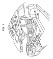
- FIG. 1 is a schematic view of the interior of a motor vehicle illustrating some of the many potential applications for lighted appliqués and trim panels.
- Each of the letter designations (A-II) indicates areas of the interior where lighting devices may be integrated into a trim component to increase the value and versatility of the vehicle. That lighting may further include such features as icons, logos, sensors and switches.
- Reference letter A is an example of instrument cluster backlighting.
- B is an example of footwell lighting for the driver.
- C is an example of how lighting/controls/touch sensors may be integrated into the infotainment center of a vehicle.
- D is an example similar to C in the center console area of the vehicle.
- E illustrates where lighting may be integrated into the PRNDL - shifter area of a console.
- F illustrates where lighting may be integrated into a cupholder area of a center console.
- G illustrates where lighting may be integrated into the storage compartment of a center console.
- H, I and J illustrate additional lighting for foot wells adjacent the center console and for rear passengers under the front seat and rear of the center console, respectively.
- K represents lighting integrated into a decorative appliqué on the instrument panel.
- L illustrates where lighting may be integrated into the glove box.
- N represents a trim insert for the door panel, often covered with textile or a perforated cover material, which may be backlit to provide a level of ambient light to the interior.
- O represents lighting to a pull cup or grip pull handle area and P represents lighting in a storage pocket.
- Q represents light at a door edge to indicate to oncoming traffic that the door is open.
- R represents lighting for puddles and outside hazards when the door is open.
- S represents lighting integrated into the pillar trim for lighting the foot well area of the second row of seating.
- T is a similar treatment applied to the top of the pillar post to provide light for assistance in entry/exit.
- U, V and W are examples of where lighting may be applied in the cargo storage area for functional lighting and to illuminate the viewing in dark or shadowed areas.
- X is a sill plate appliqué that may be applied to the sill of any opening to assist in loading/unloading under low lighting conditions and may serve as a decorative backlighting feature (logo, design, etc).
- the overhead system of the vehicle represents numerous opportunities for lighting behind molded grilles, etc.
- Y is a vanity mirror applied to a visor with lighting and sensing capabilities.
- Z is a console with map reading lighting.
- AA is a variant for lighting the vanity mirror in the visor and may provide general ambient overhead lighting for the passenger.
- BB is lighting applied to the headliner to accentuate the grab handle.
- CC is an example of dome lighting with integral electronics for assisting in entry and general lighting in the vehicle.
- DD and EE are similar lighting integrated into the overhead console area.
- FF represents an overhead decorative appliqué with lighting capability.
- GG represents an overhead lighting panel having a textile outer layer which the lighting may be seen through.
- Appliqués and trim panels may be molded and equipped with lighting capability to project light through, around and along such panels to meet the requirements of many of the above listed applications, according to the present disclosure.
- appliance it is understood to mean a molded panel having a plurality of layers, which may be used as a decorative panel to accentuate or highlight an area of a vehicle and enhance or differentiate the appearance of that area.
- trim panel it is understood to mean a molded panel having a plurality of layers, which may have sensing, switching and control functions integrated into the panel and accessible through the top layer.
- FIG . 2A is a plan view of an exemplary appliqué 10 with a lighted periphery 20, comprising a transparent outer layer 5 overlying a decorative layer 1 which is backed by another transparent plastic layer 3 (see FIG. 3 for a cross-sectional view).
- the decorative layer 1 is a film or foil having a pattern of non-transparent facets 12 on the outer sides of which layers 3, 5 have been injection molded to form a laminate.
- the outer periphery 14 of the decorative layer 1 is transparent to allow a light source (not shown) to project light through portions of the laminate and provide halo lighting.
- This type of appliqué is shown, for instance, in FIG. 1 as reference numerals E, K, M, N, R and X.
- FIG. 14 illustrates two examples of how the periphery of the appliqué 10 may be backlighted.
- FIG. 2B is a plan view of an exemplary appliqué 10 with a lighted logo 30, comprising a transparent outer layer 5 overlying a decorative layer 1 which may be backed by another transparent plastic layer 3 (see FIG. 3 for a cross-sectional view).
- the decorative layer 1 may be a film or foil having a honeycombed hexagonal or conical pattern of projections 12 and which has been injection molded between layers 3, 5 to form a laminate.
- the logo area 30 may comprise a section which is transparent or light in color in the decorative layer to highlight the logo from the remainder of the colored opaque appliqué.
- FIG. 13 illustrates one means for lighting the logo selectively from the backside.
- FIG. 3 An exemplary construction of the appliqué or trim panel of the present disclosure is shown in simplified cross-sectional view in FIG. 3 .
- the layers as shown are exaggerated in thickness for clarity of the discussion. The relative dimensions of the layers may not be as depicted.
- an appliqué 10 comprises a decorative layer 1 having a front side and a back side, which may include, but is not limited to, a foil, film, fabric, veneer, wood, paper, a coating or thin laminate which is covered with a layer 3 of a first plastic on its back side and has a top layer 5 overlying its front side.
- the top layer 5 is preferably injection molded of a transparent plastic at a thickness to provide the desired depth of image and to protect the thin decorative layer 1.
- the backing layer 3 is also injection molded and may be of any plastic material and may be transparent or tinted, pigmented or otherwise decorated to enhance the appearance of the decorative layer 1, if so desired.
- the top layer 5 may be tinted, pigmented or otherwise decorated to yield a specific appearance as desired.
- typical decorative materials may include, but, are not limited to, cloth or fabrics, metallized or painted films and foils, metal, wood grain veneers, paper, laminates formed by hydrographic or metal deposition processes, etc.
- the appliqué or trim panel may be formed according to the teachings of United States Application No. 11/428,107 filed June 30, 2006 , which is a continuation of International Application No. PCT/US2005/000170 filed January 3, 2005 and published August 4, 2005 as International Publication No. WO 2005/070647 , designating the United States, commonly assigned to the assignee of the present disclosure.
- the same modifying/repair procedure may also be applied to the back surface of a decorative layer on which a transparent layer has been molded on the front surface.
- the appliqué or trim panel may be formed according to the teachings of United States Application No. 11/532,825 filed September 18, 2006 , which is a continuation-in-part of United States Application No. 11/428,107 , which are commonly assigned to the assignee of the present disclosure.
- the preferably transparent outer layer 5 may comprise any of the transparent, preferably light stable, plastics available in the art, including but not limited to, polycarbonate, polymethyl-methacrylate, ethylene acrylate (EMA, EEA, EBA), thermoplastic urethane, polyester (PET, PEN), copolyester alloys, cyclic olefin copolymer, paly-4-methyl-1-pentene, polysulphone, allyl diglycol carbonate, allyl ester, styrene-acrylonitrile, methacrylate acrylanitrile-butadiene-styrene, polystyrene, polyamide, polyimide, polysulfone, cellulose acetate (CAB, CAP), glycol modified polyethylene terphthalate, polyvinyl chloride and blends thereof.
- plastics available in the art, including but not limited to, polycarbonate, polymethyl-methacrylate, ethylene acrylate (EMA, EEA, EBA),
- transparent it is meant that the layer has the property of transmitting light through the layer with a low degree of diffusion or haze so that bodies lying beyond the layer may be seen relatively clearly. In some cases, 85% of the light may pass through the layer, including all values and increments in the range of 85% to 99.9%, in increments of 0.1%. Diffusion or haze may be understood as the scattering of light from within or from the surface of a layer.
- the transparent plastic outer layer 5 comprises a copolymer and more particularly a cyclic olefin copolymer, such as TOPAS® 6015S-04 from Ticona, or a copolyester alloy, such as OPTIMUM® 800 Grade from Engineered Plastics Corporation.
- a copolymer and more particularly a cyclic olefin copolymer such as TOPAS® 6015S-04 from Ticona
- a copolyester alloy such as OPTIMUM® 800 Grade from Engineered Plastics Corporation.
- the appliqué 10 may be of any thickness suitable for the application for which the appliqué or trim panel is intended, typically in the range of about 1.0 mm. to about 5.0 mm. with a transparent outer layer 5 typically in the range of about 0.5 mm. to about 2.0 mm. in thickness, depending on the molding properties of the transparent resin used for the outer layer 5.
- multiple decorative layers 1, 1a may be included in the construction of the appliqué to provide a distinguishing appearance.
- the layers as shown are exaggerated in thickness for clarity of the discussion. The relative dimensions of the layers may not be as depicted.
- the appliqué or trim panel may be formed according to the teachings of United States Application No. 12/352,487 filed January 12, 2009 , which is a continuation-in-part of United States Application No. 11/532,825 filed September 18, 2006 , which is a continuation-in-part of United States Application No. 11/428,107 , which are commonly assigned to the assignee of the present disclosure.
- One or more of the decorative layers 1, 1a may include portions which are transparent allowing a colored or opaque backing layer or light to show through the layered construction.
- FIG. 4 illustrates a combination of a first decorative layer 1 backed by an injection molded layer of colored or opaque plastic 3 forming a first decorative composite which may then be inserted into a second mold set in which a second decorative layer 1a has been placed. Subsequently, a transparent plastic may be injected between the decorative layers 1 , 1a to form a transparent layer 5 and a finished appliqué 10A .
- FIG. 5 illustrates another process involving multiple decorative layers wherein a first decorative layer 1 and a second decorative layer 1a may be placed into a mold set, and a transparent resin 5 injected between the decorative layers to form an appliqué 10B.
- the second decorative layer 1a may be a bilaminate, such as manufactured by Avery Dennison Corporation comprising two carrier films, one of which has a pattern printed thereupon wherein the graphics lie between the films.
- the first decorative layer 1 may include at least some transparent portions, through which the graphics or light may be seen.
- the graphics due to the relative thickness of the transparent layer 5, may appear to be floating in the transparent layer, providing an exceptional depth of image.
- the appliqués formed and configured as described herein having portions which are transparent may be provided with backlighting to further enhance their appearance.
- portions of one or both of the decorative layers, 1, 1a may include sections which are opaque and light blocking such that specific areas may show up as black when backlighted to indicate icons, logos, arrows, emblems, etc. It is contemplated that such light blocking areas may reside in a second decorative layer 1a such that they are not visible (behind a pattern in layer 1) and are seen only when the panel is backlighted.
- Such icons, logos, arrows and emblems may overlie switches and controls for functions in the vehicle and indicate where pressure may be applied to actuate such switches and controls.
- first and second decorative layers may be different in one or more of the following characteristics: type of decorative pattern, material (polymer type), color, areas of transparency relative to areas of opacity, thickness, hardness, strength (e.g. tensile strength).
- each decorative layer may itself be composed of several layers, each with graphics or printing thereon, to provide an overall decorative appearance.
- typical decorative materials may include, but, are not limited to, cloth or fabrics, metallized or painted films and foils, metal, wood grain veneers, paper, and laminates formed by hydrographic or metal deposition processes.
- a coating may be applied to the exposed surface of any of the decorative layers 1, 1a when the mold set is open to further decorate or enhance the appearance of the resultant appliqué 10A , 10B.
- low pressure thermoplastic injection molding may be used to form the appliqué or trim component.
- Low pressure injection molding generally entails lower clamp pressure (for instance, at or below 13.789 MPa (2000 psi)) than regular injection molding processes due to one or more of the following characteristics: filling the mold while it is partially open (injection-compression), use of cascading sequential gating to distribute the flow, pre-expanding the melt, introducing a gas to fill out a short shot, low speed injection of the polymer, elimination of pack out and hold pressure, use of easy flow, relatively low melt viscosity polymers, and the use of relatively high melt index polymers (e.g.
- Polymers which may be used to form the backing layer of the appliqué or trim panel using low pressure injection molding may include, for instance, polyethylene (PE), polypropylene (PP), acrylonitrile-butadiene-styrene (ABS), poly(vinyl chloride) (PVC), polyolefins, polycarbonate (PC) and blends thereof.
- PE polyethylene
- PP polypropylene
- ABS acrylonitrile-butadiene-styrene
- PVC poly(vinyl chloride)
- PC polycarbonate
- Such low pressure molding may provide less disruption of the decorative layer, particularly if it is thin, upon injection of the polymer into the mold cavity.
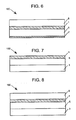
- FIGS. 6-8 Additional appliqué constructions formed by multi-shot injection molding using the processes disclosed herein are illustrated in FIGS. 6-8 .
- the layers as shown are exaggerated in thickness for clarity of the discussion. The relative dimensions of the layers may not be as depicted.
- FIG. 6 is a cross-sectional view of an appliqué 10C wherein a first decorative layer appears to be floating over a second decorative layer, in this case a coating of paint.
- a first decorative layer 1 is molded with a transparent layer 5 on both the front side and back side, followed by coating one of the exposed surfaces of the transparent layer 5 with a colored paint 7.
- FIG. 7 is a cross-sectional view of an appliqué 10D wherein a first decorative layer 1 is backed by an injection molded transparent layer 5 which is in turn backed with an opaque or colored injection molded layer 3.
- This construction provides a visual effect that whatever is printed on the decorative film may appear to be suspended deep within the transparent layer and on the surface of the opaque or colored layer.
- the colored layer may be white, and the graphics of the decorative layer may appear to be floating on the surface of the white substrate.
- the decorative film layer may have graphics printed on or within the layer as well as transparent areas which may allow one to see the colored layer or light through the film and transparent layer.
- FIG. 8 is a cross-sectional view of an appliqué 10E wherein the paint layer 7 in FIG. 6 is replaced with an injection molded colored backing layer 3 of FIG. 7 .
- the backing layer 3 may further include integral or insert-molded fastening means (not shown).
- the decorative layer 1 for any of the embodiments shown in the figures may include portions which are transparent allowing light from a light source to show through the layered construction.
- light source it is understood to mean an artificial source of light that may be used in conjunction with a plastic panel to transmit light through a portion of that panel.
- backlighted or “backlit” it is understood to mean the providing of a source of light behind one or more layers or surfaces and the projecting of light through at least a portion of such layers so that the foreground appears sharper in contrast to the background. This may allow all or portions of a decorative layer to be enhanced or brightened in appearance.
- Optically coupled refers to any connection, coupling, link or the like by which optical signals carried by one optical system element are imparted to the cating" or “coupled” element. Such “optically coupled” devices are not necessarily directly connected to one another and may be separated by intermediate optical components or devices. Likewise, the terms “connected” or “coupled” as used herein in regard to physical connections or couplings is a relative term and does not require a direct physical connection.
- FIG. 9 is a cross-section of a perspective view of an appliqué or trim panel according to another embodiment of the present disclosure, illustrating an integrally formed light pipe. While panels may be backlighted using a variety of light sources, including a light pipe, the present disclosure may allow "edge lighting" by utilizing the runner from the injection molding of the transparent outer layer 5 as a light pipe. When a polymer is injection molded, particularly to form a relatively thin cross-section such as the transparent layer of the present disclosure, for instance less than or equal to 2 mm, a somewhat larger runner may feed a relatively narrow gate to introduce the polymer preferably under laminar flow into the injection cavity.
- a runner may extend along one or both sides of and for nearly the entire length of the appliqué.
- a runner is understood as an elongated section of plastic material, that serves to introduce plastic into a selected location in a mold for forming a plastic part (via laminar flow) which elongated section is also configured to remain permanently attached to the part and to convey light from a light source to all or a portion of the molded plastic part.
- the runner is not a conventional runner in the sense that a conventional runner is typically designed to be removed and does not take into consideration light transmission requirements.
- an appliqué or trim panel 10F may comprise a decorative layer 1, backed by a backing layer 3 and having a transparent layer 5 molded onto the front side.
- a runner 40 usually of round or half-round cross-section, about 10-15 mm. in diameter may feed a gate 42 having an opening of about 1 mm. to allow the thickness of the transparent layer 5 to be filled out.
- it may function as a light pipe by optically coupling a light source to one or both ends or along its length (see FIG. 12 ).
- FIG. 12 As shown in schematic partial cross-sectional view in FIG.
- the runner 40 may be covered by an adjacent trim panel 44 such that the runner or light pipe is not visible to the occupant in the vehicle and may provide a lighted layer ( 5 ) in the appliqué 10F . It is contemplated that as shown in FIG. 9 , the decorative layer 1 may the removed, yet the runner 40 may still provide (with an appropriate light sourcé) illumination through the runner 40 and into all or a portion of the transparent layer 5 .
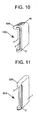
- FIG. 10 is a cross-section of a perspective view of the appliqué or trim panel of FIG. 9 , illustrating a different location for the integrated light pipe.
- the runner 40A is molded behind the appliqué or trim panel 10G by using retractable loose pieces in the mold that would be retracted after molding.
- the runner 40A does not become part of the front surface of the appliqué.
- a roughened surface or molded-in pattern, for instance of sawtoothed or scalloped grooves, 46 may be provided along a portion of the runner 40A to assist in directing the light from exiting the runner by Total Internal Reflection (TIR). Reflective strips may be locally applied or molded-in to further direct the light as desired.
- TIR Total Internal Reflection
- FIG. 11 is a cross-section of a perspective view of the appliqué or trim panel of FIG. 9 , illustrating an integrated light pipe 40B formed from the runner in the molding process where the runner is left exposed as a decorative and functional part of the appliqué 10F .
- This may provide a "halo-like" effect to a portion or all of the periphery of the appliqué in addition to lighting the transparent layer 5 of the appliqué.
- the decorative layer 1 may overlie the transparent lighted layer 5 to aid in accentuating images, graphics, etc. in the decorative layer.
- the appliqué or trim panel may not include a decorative layer but instead comprise an injection molded transparent layer over a colored backing layer and that such edge lighting may provide an enhanced appearance of the backing layer.
- FIG. 12 is a backside view of the appliqué or trim panel of FIG. 10 illustrating one exemplary embodiment of the integration of a light source.
- the backing layer 3 of the appliqué 10G is shown along with the clear runner or integrated light pipe 40A.
- a connector 60 is provided which may include a light source 62 such as a light emitting diode (LED) or other source of light which may be used to light a portion of the appliqué 10G.
- a light source 62 such as a light emitting diode (LED) or other source of light which may be used to light a portion of the appliqué 10G.
- LED light emitting diode
- the connector 60 may overlap a portion or all of the end of the runner 40A and may include protrusions 66 which may be spaced apart by less than the diameter of the runner 40A such that they may be spread slightly upon engaging the end of the runner and may grasp the runner to provide optical coupling of the light source 62 with the light pipe 40A. Either or both of the protrusions 66 and the end of the runner 40A may further include detents, ridges and tapered portions such that a mechanical coupling of the connector 60 and runner/integrated light pipe 40A may be made.
- Wires 64 are shown which connect the light source to a power source. LED's may work well in such applications as they are relatively small in size and focused in intensity.
- the light source 62 may be contained within the connector 60 and include socket and reflector (not shown). An end of the light source will preferably be located closely adjacent to or in contact with the end of the runner/integrated light pipe 40A so that light may be transported along the light pipe and/or across at least a portion of the surface of the appliqué 10G.
- FIG. 13 is a cross-sectional view through the center of the appliqué of FIG. 2B illustrating an integration of a light source to selectively light a center area, such as a logo.
- an appliqué 10 may comprise a decorative layer 1, such as cloth, wood, paper, a laminate, film or foil having at least one portion which is transparent to light and may include graphic patterns, logos, text, icons, etc. capable of being lighted from behind.
- FIG. 2B illustrates a logo which is selectively lighted from behind to distinguish the log from its surroundings.
- the appliqué 10 further comprises a transparent outer layer 5 and a backing layer 3 which may be at least selectively transparent to allow the light to be transmitted through transparent areas of the decorative layer 1 and the transparent outer layer 5.
- the backing layer 3 may include areas that are opaque and may act as a blocking layer to prevent light transmission locally.
- a back panel 70 holds a printed circuit board or wiring panel 74 to which is connected a light source 74.
- the light source may be of any type, for instance, incandescent, fluorescent, LED, electroluminescent, neon, argon, etc.
- a plurality of bulbs may be used to provide uniform lighting or to selectively light various areas of the appliqué 10.
- light pipes and light guides may also be used to provide light for various areas of the appliqué.
- Reflectors, diffusers, diverters and shields may also be configured within the back panel to provide types of special effects. Heat insulating elements as well as convection means for hot air may be useful.
- FIG. 14 is a cross-sectional view through the center of the appliqué of FIG. 2A illustrating other exemplary embodiments of attachment of a light source to the appliqué 10.
- the basic construction of the appliqué 10 of FIG. 2A includes a decorative layer 1 having some transparent portions, an outer transparent layer 5 and a backing layer 3 which may also have transparent portions.
- the backing layer 3 may include mounting features 80 attached to the backside of the backing layer 3 which may accept various types of light sources for backlighting the periphery 20 of appliqué 10.
- FIG. 14 illustrates an acrylic light pipe 90 and an LED light module 60' either of which may be used to selectively light edge portions of the appliqué 10 by transmitting light through transparent portions of the backing layer 3, decorative layer 1 and transparent outer layer 5.
- Such light sources may also be positioned to light a center logo as shown in FIG. 2 B.
- the mounting features 80 and/or the light sources 90, 92 may further include detents 82,84, ridges and tapered portions such that a mechanical coupling of the light sources 90, 92 and the mounting features 80 on the backside of the appliqué 10 may be made. Since the backing layer 3 may be injection molded behind the decorative layer 1, it may be preferable that the mounting features 80 be integrally molded with the backing layer.
- FIG. 15 is a cross-sectional view through the center of the appliqué of FIG. 2B illustrating another exemplary embodiment of attachment of a light source to the appliqué 10.
- an electroluminescent light film 100 may be adhesively attached, for instance, with a pressure sensitive adhesive (PSA) to the backside of the backing layer 3 of appliqué 10 and provide full area lighting or selective backlighting to the appliqué.
- PSA pressure sensitive adhesive
Landscapes
- Engineering & Computer Science (AREA)
- Mechanical Engineering (AREA)
- Manufacturing & Machinery (AREA)
- Vehicle Interior And Exterior Ornaments, Soundproofing, And Insulation (AREA)
- Arrangements Of Lighting Devices For Vehicle Interiors, Mounting And Supporting Thereof, Circuits Therefore (AREA)
Description
- The present disclosure relates to trim panels and appliqués used in the transportation industry and, more particularly, to the selective illumination of all or a portion of the front surface of such trim panel or appliqué by backlighting or edge-lighting.
- Transportation vehicles, particularly automobiles, may be marketed and sold on the basis of differentiation over other competitive models. Differentiation may be by style or color, and is often accomplished by using trim panels or appliqués on the interior or exterior of the vehicle which denote different levels of luxury, price or value. These appliqués or panels may also form protective coverings for areas that protrude from adjacent surfaces. These panels are generally color-coordinated with the adjacent surfaces of the vehicle but may also be bright, reflective, wood-grained, marbleized or metallized in appearance.
- Originally, "real" wood appliqués and finished metal panels were used, however, their popularity suffered due to their high cost and limited durability. Subsequently, wood veneers and films with vacuum-deposited metal layers found favor, however, these solutions did not produce the look of luxury or the extended durability required in today's market.
- Various proposals have been suggested and practiced for the manufacture of plastic composites for use as automotive interior trim and exterior trim panels or appliqués.
- Attention is directed particularly to United States Application No.
11/428,107 filed June 30, 2006 PCT/US2005/000170 filed January 3, 2005 and published August 4, 2005 as International Publication No.WO 2005/070647 , designating the United States, and to United States Application No.11/532,825 filed September 18, 2006 11/428,107 - These applications further relate to a production method for providing a trim panel or appliqué wherein a decorative layer is positioned between two mold halves and a plastic material is injection molded against one surface of the decorative layer to form a decorative composite Subsequently, the decorative composite is transferred to a second tool where a, preferably transparent, plastic material is injection molded against the front side of the decorative layer. The plastic materials may be of the same or different composition, but preferably one of the materials is a relatively transparent plastic which when provided at an appropriate thickness, yields an appearance of the decorative layer lying under the top surface of the transparent layer, thus having an exceptional depth of image. The decorative layer may comprise a wide variety of thin materials to distinguish its appearance, including, but not limited to; fabric, wood, foil, metal, paper and plastic.
- Attention is further directed to United States Application No.
12/352,487 filed January 12, 2009 11/532,825 - There are a myriad of locations within a motor vehicle or other transportation means where lighting is desired to provide ambient lighting for aesthetics and effect, orientation lighting for safety and convenience and functional lighting for reading, etc. The integration of electronics into lighting devices in the automobile and, more particularly, lighting has become a selling feature and further enhances the ambiance of the interior environment associated with traveling.
- It is contemplated that lighting may be integrated into trim panels and appliqués through backlighting or edge-lighting of the panels to provide even further differentiation and value. Document
DE-A1-102004044035 discloses an appliqué or trim panel in accordance with the preamble ofclaim 1. - The present invention relates to an appliqué or trim panel according to
claim 1 and to a method of producing an appliqué or trim panel according toclaim 13. Preferred embodiments of the invention are defined in the dependent claims. - The features, operation and advantages of the invention may be better understood from the following detailed description of the preferred embodiments taken in conjunction with the attached drawings, in which
-
FIG. 1 is a schematic view of a portion of the interior of a motor vehicle illustrating some of the many potential applications for lighted trim panels and appliqués. -
FIG. 2A is a plan view of an exemplary appliqué with a lighted periphery, according to the present disclosure. -
FIG. 2B is a plan view of an exemplary appliqué with a lighted logo, according to the present disclosure. -
FIG. 3 is an enlarged cross-sectional view of a portion of an exemplary appliqué or trim panel, according to the present disclosure. -
FIGS. 4-8 are enlarged cross-sectional views of portions of exemplary appliqués or trim panels utilizing multiple decorative layers and transparent and transparent/opaque injection molded layers. -
FIG. 9 is a cross-section of a perspective view of an appliqué or trim panel according to another embodiment of the present disclosure, illustrating an integral light pipe. -
FIG. 9A is a partial cross-sectional view of the appliqué ofFIG. 9 showing a trim panel to cover the runner/light pipe. -
FIG. 10 is a cross-section of a perspective view of the appliqué or trim panel ofFIG. 9 , illustrating a different location for the integrated light pipe. -
FIG. 11 is a cross-section of a perspective view of an appliqué or trim panel ofFIG. 9 , illustrating an integral light pipe which may form a portion of the visible surface of the appliqué or trim panel. -
FIG. 12 is a backside view of the appliqué or trim panel ofFIG. 10 illustrating the integration of a light source. -
FIG. 13 is a cross-sectional view through the center of the appliqué ofFIG. 2B illustrating an integration of a light source that may backlight the center of an appliqué. -
FIG. 14 is a cross-sectional view through the appliqué ofFIG. 2A illustrating an integration of a light source that may backlight the periphery of an appliqué. -
FIG. 15 is another cross-sectional view through the appliqué ofFIG. 2A illustrating an integration of another light source that may backlight the periphery of an appliqué. -
FIG. 1 is a schematic view of the interior of a motor vehicle illustrating some of the many potential applications for lighted appliqués and trim panels. Each of the letter designations (A-II) indicates areas of the interior where lighting devices may be integrated into a trim component to increase the value and versatility of the vehicle. That lighting may further include such features as icons, logos, sensors and switches. - Reference letter A is an example of instrument cluster backlighting. B is an example of footwell lighting for the driver. C is an example of how lighting/controls/touch sensors may be integrated into the infotainment center of a vehicle. D is an example similar to C in the center console area of the vehicle. E illustrates where lighting may be integrated into the PRNDL - shifter area of a console. F illustrates where lighting may be integrated into a cupholder area of a center console. G illustrates where lighting may be integrated into the storage compartment of a center console. H, I and J illustrate additional lighting for foot wells adjacent the center console and for rear passengers under the front seat and rear of the center console, respectively. K represents lighting integrated into a decorative appliqué on the instrument panel. L illustrates where lighting may be integrated into the glove box.
- Turning to door trim, M illustrates how lighting may be used to highlight the interior door handle. N represents a trim insert for the door panel, often covered with textile or a perforated cover material, which may be backlit to provide a level of ambient light to the interior. O represents lighting to a pull cup or grip pull handle area and P represents lighting in a storage pocket. Q represents light at a door edge to indicate to oncoming traffic that the door is open. R represents lighting for puddles and outside hazards when the door is open.
- Turning to sidewall and storage areas in the vehicle, S represents lighting integrated into the pillar trim for lighting the foot well area of the second row of seating. T is a similar treatment applied to the top of the pillar post to provide light for assistance in entry/exit. U, V and W are examples of where lighting may be applied in the cargo storage area for functional lighting and to illuminate the viewing in dark or shadowed areas. X is a sill plate appliqué that may be applied to the sill of any opening to assist in loading/unloading under low lighting conditions and may serve as a decorative backlighting feature (logo, design, etc).
- The overhead system of the vehicle represents numerous opportunities for lighting behind molded grilles, etc. Y is a vanity mirror applied to a visor with lighting and sensing capabilities. Z is a console with map reading lighting. AA is a variant for lighting the vanity mirror in the visor and may provide general ambient overhead lighting for the passenger. BB is lighting applied to the headliner to accentuate the grab handle. CC is an example of dome lighting with integral electronics for assisting in entry and general lighting in the vehicle. DD and EE are similar lighting integrated into the overhead console area. FF represents an overhead decorative appliqué with lighting capability. GG represents an overhead lighting panel having a textile outer layer which the lighting may be seen through. HH is a brake light formed according to the present disclosure. II is an overhead panel integrated into the roof portion of the rear storage area.
- Appliqués and trim panels may be molded and equipped with lighting capability to project light through, around and along such panels to meet the requirements of many of the above listed applications, according to the present disclosure.
- By "appliqué" it is understood to mean a molded panel having a plurality of layers, which may be used as a decorative panel to accentuate or highlight an area of a vehicle and enhance or differentiate the appearance of that area.
- By "trim panel" it is understood to mean a molded panel having a plurality of layers, which may have sensing, switching and control functions integrated into the panel and accessible through the top layer.
-
FIG. 2A is a plan view of anexemplary appliqué 10 with a lightedperiphery 20, comprising a transparentouter layer 5 overlying adecorative layer 1 which is backed by another transparent plastic layer 3 (seeFIG. 3 for a cross-sectional view). Thedecorative layer 1 is a film or foil having a pattern ofnon-transparent facets 12 on the outer sides of which layers 3, 5 have been injection molded to form a laminate. Theouter periphery 14 of thedecorative layer 1 is transparent to allow a light source (not shown) to project light through portions of the laminate and provide halo lighting. This type of appliqué is shown, for instance, inFIG. 1 as reference numerals E, K, M, N, R and X.FIG. 14 illustrates two examples of how the periphery of theappliqué 10 may be backlighted. -
FIG. 2B is a plan view of anexemplary appliqué 10 with a lightedlogo 30, comprising a transparentouter layer 5 overlying adecorative layer 1 which may be backed by another transparent plastic layer 3 (seeFIG. 3 for a cross-sectional view). Thedecorative layer 1 may be a film or foil having a honeycombed hexagonal or conical pattern ofprojections 12 and which has been injection molded betweenlayers logo area 30 may comprise a section which is transparent or light in color in the decorative layer to highlight the logo from the remainder of the colored opaque appliqué.FIG. 13 illustrates one means for lighting the logo selectively from the backside. - An exemplary construction of the appliqué or trim panel of the present disclosure is shown in simplified cross-sectional view in
FIG. 3 . The layers as shown are exaggerated in thickness for clarity of the discussion. The relative dimensions of the layers may not be as depicted. - Here, an
appliqué 10 comprises adecorative layer 1 having a front side and a back side, which may include, but is not limited to, a foil, film, fabric, veneer, wood, paper, a coating or thin laminate which is covered with alayer 3 of a first plastic on its back side and has atop layer 5 overlying its front side. Thetop layer 5 is preferably injection molded of a transparent plastic at a thickness to provide the desired depth of image and to protect the thindecorative layer 1. Thebacking layer 3 is also injection molded and may be of any plastic material and may be transparent or tinted, pigmented or otherwise decorated to enhance the appearance of thedecorative layer 1, if so desired. Likewise, thetop layer 5 may be tinted, pigmented or otherwise decorated to yield a specific appearance as desired. As noted above, typical decorative materials may include, but, are not limited to, cloth or fabrics, metallized or painted films and foils, metal, wood grain veneers, paper, laminates formed by hydrographic or metal deposition processes, etc. The appliqué or trim panel may be formed according to the teachings of United States Application No.11/428,107 filed June 30, 2006 PCT/US2005/000170 filed January 3, 2005 and published August 4, 2005 as International Publication No.WO 2005/070647 , designating the United States, commonly assigned to the assignee of the present disclosure. - Particularly in the case of decorative layers which are somewhat porous, such as cloth, fabric, wood or wood based laminates, paper, etc., it may be desirable to modify the visual appearance of the exposed surface of the decorative material after the backing layer has been injected. This may be the case when the heat and pressure of the first injection of polymer as a backing layer may change the visual characteristics of the exposed surface of the decorative layer. This then may allow a change in color, gloss, texture, pattern, etc., to be imparted to the exposed surface of the
decorative layer 1 and any exposedbacking layer 3. The procedure may also be used to provide a repair to the exposed surface of thedecorative layer 1 for any defects that may have occurred during the injection of thebacking layer 3. This may particularly be an issue with wood laminates or veneers which may have an exposed surface which "opens up" or becomes more porous due to the heat and pressure of injection of thebacking layer 3. The same modifying/repair procedure may also be applied to the back surface of a decorative layer on which a transparent layer has been molded on the front surface. The appliqué or trim panel may be formed according to the teachings of United States Application No.11/532,825 filed September 18, 2006 11/428,107 - The preferably transparent
outer layer 5 may comprise any of the transparent, preferably light stable, plastics available in the art, including but not limited to, polycarbonate, polymethyl-methacrylate, ethylene acrylate (EMA, EEA, EBA), thermoplastic urethane, polyester (PET, PEN), copolyester alloys, cyclic olefin copolymer, paly-4-methyl-1-pentene, polysulphone, allyl diglycol carbonate, allyl ester, styrene-acrylonitrile, methacrylate acrylanitrile-butadiene-styrene, polystyrene, polyamide, polyimide, polysulfone, cellulose acetate (CAB, CAP), glycol modified polyethylene terphthalate, polyvinyl chloride and blends thereof. - By "transparent" it is meant that the layer has the property of transmitting light through the layer with a low degree of diffusion or haze so that bodies lying beyond the layer may be seen relatively clearly. In some cases, 85% of the light may pass through the layer, including all values and increments in the range of 85% to 99.9%, in increments of 0.1%. Diffusion or haze may be understood as the scattering of light from within or from the surface of a layer.
- Preferably, the transparent plastic
outer layer 5 comprises a copolymer and more particularly a cyclic olefin copolymer, such as TOPAS® 6015S-04 from Ticona, or a copolyester alloy, such as OPTIMUM® 800 Grade from Engineered Plastics Corporation. - The
appliqué 10 may be of any thickness suitable for the application for which the appliqué or trim panel is intended, typically in the range of about 1.0 mm. to about 5.0 mm. with a transparentouter layer 5 typically in the range of about 0.5 mm. to about 2.0 mm. in thickness, depending on the molding properties of the transparent resin used for theouter layer 5. - In another exemplary embodiment, as illustrated in
FIGS. 4-5 , multipledecorative layers 12/352,487 filed January 12, 2009 11/532,825 filed September 18, 2006 11/428,107 - One or more of the
decorative layers FIG. 4 illustrates a combination of a firstdecorative layer 1 backed by an injection molded layer of colored oropaque plastic 3 forming a first decorative composite which may then be inserted into a second mold set in which a seconddecorative layer 1a has been placed. Subsequently, a transparent plastic may be injected between thedecorative layers transparent layer 5 and afinished appliqué 10A. -
FIG. 5 illustrates another process involving multiple decorative layers wherein a firstdecorative layer 1 and a seconddecorative layer 1a may be placed into a mold set, and atransparent resin 5 injected between the decorative layers to form anappliqué 10B. In this example, the seconddecorative layer 1a may be a bilaminate, such as manufactured by Avery Dennison Corporation comprising two carrier films, one of which has a pattern printed thereupon wherein the graphics lie between the films. The firstdecorative layer 1 may include at least some transparent portions, through which the graphics or light may be seen. The graphics, due to the relative thickness of thetransparent layer 5, may appear to be floating in the transparent layer, providing an exceptional depth of image. As a further feature of the invention, the appliqués formed and configured as described herein having portions which are transparent, may be provided with backlighting to further enhance their appearance. Further, portions of one or both of the decorative layers, 1, 1a may include sections which are opaque and light blocking such that specific areas may show up as black when backlighted to indicate icons, logos, arrows, emblems, etc. It is contemplated that such light blocking areas may reside in a seconddecorative layer 1a such that they are not visible (behind a pattern in layer 1) and are seen only when the panel is backlighted. - Such icons, logos, arrows and emblems may overlie switches and controls for functions in the vehicle and indicate where pressure may be applied to actuate such switches and controls.
- It may therefore be understood that the first and second decorative layers may be different in one or more of the following characteristics: type of decorative pattern, material (polymer type), color, areas of transparency relative to areas of opacity, thickness, hardness, strength (e.g. tensile strength). In addition, each decorative layer may itself be composed of several layers, each with graphics or printing thereon, to provide an overall decorative appearance.
- As noted above, typical decorative materials may include, but, are not limited to, cloth or fabrics, metallized or painted films and foils, metal, wood grain veneers, paper, and laminates formed by hydrographic or metal deposition processes.
- A coating may be applied to the exposed surface of any of the
decorative layers resultant appliqué - In addition, low pressure thermoplastic injection molding may be used to form the appliqué or trim component. Low pressure injection molding generally entails lower clamp pressure (for instance, at or below 13.789 MPa (2000 psi)) than regular injection molding processes due to one or more of the following characteristics: filling the mold while it is partially open (injection-compression), use of cascading sequential gating to distribute the flow, pre-expanding the melt, introducing a gas to fill out a short shot, low speed injection of the polymer, elimination of pack out and hold pressure, use of easy flow, relatively low melt viscosity polymers, and the use of relatively high melt index polymers (e.g. melt index values greater than 5, more preferably melt flow values in the range of 5-50, including all values therein, in 1.0 increments). Polymers which may be used to form the backing layer of the appliqué or trim panel using low pressure injection molding may include, for instance, polyethylene (PE), polypropylene (PP), acrylonitrile-butadiene-styrene (ABS), poly(vinyl chloride) (PVC), polyolefins, polycarbonate (PC) and blends thereof. Such low pressure molding may provide less disruption of the decorative layer, particularly if it is thin, upon injection of the polymer into the mold cavity.
- Additional appliqué constructions formed by multi-shot injection molding using the processes disclosed herein are illustrated in
FIGS. 6-8 . The layers as shown are exaggerated in thickness for clarity of the discussion. The relative dimensions of the layers may not be as depicted. -
FIG. 6 is a cross-sectional view of anappliqué 10C wherein a first decorative layer appears to be floating over a second decorative layer, in this case a coating of paint. Here, a firstdecorative layer 1 is molded with atransparent layer 5 on both the front side and back side, followed by coating one of the exposed surfaces of thetransparent layer 5 with a colored paint 7. -
FIG. 7 is a cross-sectional view of anappliqué 10D wherein a firstdecorative layer 1 is backed by an injection moldedtransparent layer 5 which is in turn backed with an opaque or colored injection moldedlayer 3. This construction provides a visual effect that whatever is printed on the decorative film may appear to be suspended deep within the transparent layer and on the surface of the opaque or colored layer. For instance, the colored layer may be white, and the graphics of the decorative layer may appear to be floating on the surface of the white substrate. The decorative film layer may have graphics printed on or within the layer as well as transparent areas which may allow one to see the colored layer or light through the film and transparent layer. -
FIG. 8 is a cross-sectional view of anappliqué 10E wherein the paint layer 7 inFIG. 6 is replaced with an injection moldedcolored backing layer 3 ofFIG. 7 . Thebacking layer 3 may further include integral or insert-molded fastening means (not shown). - The
decorative layer 1 for any of the embodiments shown in the figures may include portions which are transparent allowing light from a light source to show through the layered construction. - By "light source" it is understood to mean an artificial source of light that may be used in conjunction with a plastic panel to transmit light through a portion of that panel.
- As used herein, "backlighted" or "backlit" it is understood to mean the providing of a source of light behind one or more layers or surfaces and the projecting of light through at least a portion of such layers so that the foreground appears sharper in contrast to the background. This may allow all or portions of a decorative layer to be enhanced or brightened in appearance.
- "Optically coupled" as used herein refer to any connection, coupling, link or the like by which optical signals carried by one optical system element are imparted to the cating" or "coupled" element. Such "optically coupled" devices are not necessarily directly connected to one another and may be separated by intermediate optical components or devices. Likewise, the terms "connected" or "coupled" as used herein in regard to physical connections or couplings is a relative term and does not require a direct physical connection.
-
FIG. 9 is a cross-section of a perspective view of an appliqué or trim panel according to another embodiment of the present disclosure, illustrating an integrally formed light pipe. While panels may be backlighted using a variety of light sources, including a light pipe, the present disclosure may allow "edge lighting" by utilizing the runner from the injection molding of the transparentouter layer 5 as a light pipe. When a polymer is injection molded, particularly to form a relatively thin cross-section such as the transparent layer of the present disclosure, for instance less than or equal to 2 mm, a somewhat larger runner may feed a relatively narrow gate to introduce the polymer preferably under laminar flow into the injection cavity. - For appliqués or panels having a relatively high length to width ratio, the runner may extend along one or both sides of and for nearly the entire length of the appliqué. Accordingly, in the context of the present invention, a runner is understood as an elongated section of plastic material, that serves to introduce plastic into a selected location in a mold for forming a plastic part (via laminar flow) which elongated section is also configured to remain permanently attached to the part and to convey light from a light source to all or a portion of the molded plastic part. In such regard, the runner is not a conventional runner in the sense that a conventional runner is typically designed to be removed and does not take into consideration light transmission requirements.
- As shown in
FIG. 9 , an appliqué ortrim panel 10F may comprise adecorative layer 1, backed by abacking layer 3 and having atransparent layer 5 molded onto the front side. Arunner 40 usually of round or half-round cross-section, about 10-15 mm. in diameter may feed agate 42 having an opening of about 1 mm. to allow the thickness of thetransparent layer 5 to be filled out. Rather than trimming off therunner 40 after molding, since it is molded of the same transparent plastic as thetransparent layer 5, it may function as a light pipe by optically coupling a light source to one or both ends or along its length (seeFIG. 12 ). As shown in schematic partial cross-sectional view inFIG. 9A , therunner 40 may be covered by anadjacent trim panel 44 such that the runner or light pipe is not visible to the occupant in the vehicle and may provide a lighted layer (5) in theappliqué 10F. It is contemplated that as shown inFIG. 9 , thedecorative layer 1 may the removed, yet therunner 40 may still provide (with an appropriate light sourcé) illumination through therunner 40 and into all or a portion of thetransparent layer 5. -
FIG. 10 is a cross-section of a perspective view of the appliqué or trim panel ofFIG. 9 , illustrating a different location for the integrated light pipe. In this case, therunner 40A is molded behind the appliqué ortrim panel 10G by using retractable loose pieces in the mold that would be retracted after molding. Thus, therunner 40A does not become part of the front surface of the appliqué. A roughened surface or molded-in pattern, for instance of sawtoothed or scalloped grooves, 46 may be provided along a portion of therunner 40A to assist in directing the light from exiting the runner by Total Internal Reflection (TIR). Reflective strips may be locally applied or molded-in to further direct the light as desired. -
FIG. 11 is a cross-section of a perspective view of the appliqué or trim panel ofFIG. 9 , illustrating anintegrated light pipe 40B formed from the runner in the molding process where the runner is left exposed as a decorative and functional part of theappliqué 10F. This may provide a "halo-like" effect to a portion or all of the periphery of the appliqué in addition to lighting thetransparent layer 5 of the appliqué. In this instance, thedecorative layer 1 may overlie the transparent lightedlayer 5 to aid in accentuating images, graphics, etc. in the decorative layer. - With any of the integrated runners which may form a light pipe in
FIGS. 9-11 , it is contemplated that the appliqué or trim panel may not include a decorative layer but instead comprise an injection molded transparent layer over a colored backing layer and that such edge lighting may provide an enhanced appearance of the backing layer. -
FIG. 12 is a backside view of the appliqué or trim panel ofFIG. 10 illustrating one exemplary embodiment of the integration of a light source. In this view, thebacking layer 3 of theappliqué 10G is shown along with the clear runner or integratedlight pipe 40A. To supply light to therunner 40A, aconnector 60 is provided which may include alight source 62 such as a light emitting diode (LED) or other source of light which may be used to light a portion of theappliqué 10G. Theconnector 60 may overlap a portion or all of the end of therunner 40A and may includeprotrusions 66 which may be spaced apart by less than the diameter of therunner 40A such that they may be spread slightly upon engaging the end of the runner and may grasp the runner to provide optical coupling of thelight source 62 with thelight pipe 40A. Either or both of theprotrusions 66 and the end of therunner 40A may further include detents, ridges and tapered portions such that a mechanical coupling of theconnector 60 and runner/integrated light pipe 40A may be made.Wires 64 are shown which connect the light source to a power source. LED's may work well in such applications as they are relatively small in size and focused in intensity. Thelight source 62 may be contained within theconnector 60 and include socket and reflector (not shown). An end of the light source will preferably be located closely adjacent to or in contact with the end of the runner/integrated light pipe 40A so that light may be transported along the light pipe and/or across at least a portion of the surface of theappliqué 10G. -
FIG. 13 is a cross-sectional view through the center of the appliqué ofFIG. 2B illustrating an integration of a light source to selectively light a center area, such as a logo. Here, as shown inFIG. 3 , anappliqué 10 may comprise adecorative layer 1, such as cloth, wood, paper, a laminate, film or foil having at least one portion which is transparent to light and may include graphic patterns, logos, text, icons, etc. capable of being lighted from behind.FIG. 2B illustrates a logo which is selectively lighted from behind to distinguish the log from its surroundings. Theappliqué 10 further comprises a transparentouter layer 5 and abacking layer 3 which may be at least selectively transparent to allow the light to be transmitted through transparent areas of thedecorative layer 1 and the transparentouter layer 5. Thebacking layer 3 may include areas that are opaque and may act as a blocking layer to prevent light transmission locally. Aback panel 70 holds a printed circuit board orwiring panel 74 to which is connected alight source 74. The light source may be of any type, for instance, incandescent, fluorescent, LED, electroluminescent, neon, argon, etc. A plurality of bulbs may be used to provide uniform lighting or to selectively light various areas of theappliqué 10. In addition to individual bulbs, light pipes and light guides may also be used to provide light for various areas of the appliqué. Reflectors, diffusers, diverters and shields may also be configured within the back panel to provide types of special effects. Heat insulating elements as well as convection means for hot air may be useful. -
FIG. 14 is a cross-sectional view through the center of the appliqué ofFIG. 2A illustrating other exemplary embodiments of attachment of a light source to theappliqué 10. As described inFIG. 3 , the basic construction of theappliqué 10 ofFIG. 2A includes adecorative layer 1 having some transparent portions, an outertransparent layer 5 and abacking layer 3 which may also have transparent portions. Thebacking layer 3 may include mountingfeatures 80 attached to the backside of thebacking layer 3 which may accept various types of light sources for backlighting theperiphery 20 ofappliqué 10.FIG. 14 illustrates anacrylic light pipe 90 and an LED light module 60' either of which may be used to selectively light edge portions of theappliqué 10 by transmitting light through transparent portions of thebacking layer 3,decorative layer 1 and transparentouter layer 5. Such light sources may also be positioned to light a center logo as shown inFIG. 2 B. The mounting features 80 and/or thelight sources 90, 92 may further includedetents light sources 90, 92 and the mounting features 80 on the backside of theappliqué 10 may be made. Since thebacking layer 3 may be injection molded behind thedecorative layer 1, it may be preferable that the mounting features 80 be integrally molded with the backing layer. -
FIG. 15 is a cross-sectional view through the center of the appliqué ofFIG. 2B illustrating another exemplary embodiment of attachment of a light source to theappliqué 10. Here, an electroluminescentlight film 100 may be adhesively attached, for instance, with a pressure sensitive adhesive (PSA) to the backside of thebacking layer 3 ofappliqué 10 and provide full area lighting or selective backlighting to the appliqué.
Claims (19)
- An appliqué or trim panel having edges, comprising;
an outer layer (5), wherein said outer layer (5) comprises a transparent plastic;
wherein said outer layer (5) includes a runner integrally formed along one or more of said edges configured as a light pipe (40); and said light pipe (40) is optically coupled with at least one light source to illuminate at least a portion of said appliqué or trim panel; characterized in that the appliqué or trim panel comprises a plastic backing layer (3); the outer layer (5) being formed on said backing layer (3), wherein said runner is an elongated section of plastic material that serves to introduce plastic material into a selected location in a mold for forming the outer layer and the runner, which elongated section remains permanently attached to the outer layer. - The appliqué or trim panel of claim 1 wherein said runner is located substantially along said edge and is covered from view by an adjacent opaque trim panel.
- The appliqué or trim panel of claim 1 wherein said runner is located substantially along said edge and forms a visible lighted edge.
- The appliqué or trim panel of claim one of the preceding claims wherein said runner is located substantially behind said backing layer.
- An appliqué or trim panel as defined in one of the preceding claims, comprising;
a decorative layer (1) having a top surface and a back surface and including one or more areas capable of transmitting light;
said plastic backing layer (3) formed on said back surface of said decorative layer (1), said backing layer (3) having a back surface and including areas capable of transmitting light;
said outer layer (5) formed on said top surface of said decorative layer (1), wherein said outer layer (5)comprises a transparent plastic; and
at least one light source located behind said plastic backing layer (3) which is capable of projecting light through said areas capable of transmitting light in said plastic backing layer (3), through said areas capable of transmitting light in said decorative layer (1) and through said transparent plastic outer layer (5) to illuminate at least a portion of said appliqué or trim panel. - The appliqué or trim panel of claim 5 wherein said decorative layer (1) comprises one of a film, a foil, a laminate, a veneer, a fabric, paper or a coating.
- The appliqué or trim panel of claim 5 or 6 wherein a light blocking layer comprises a portion of said decorative layer (1) or said backing layer.
- The appliqué or trim panel of one of the preceding claims wherein said transparent plastic comprises polycarbonate, poly(methyl methacrylate), thermoplastic urethane, polyester, copolyester alloy, cyclic olefin copolymer, poly-4-methyl-1-pentene, polysulphone, allyl diglycol carbonate, allyl ester, styrene-acrylonitrile, polystyrene, polyvinyl chloride and blends, alloys and combinations thereof.
- The appliqué or trim panel of one of the preceding claims wherein one or more of said backing layer and said outer layer (5) include one or more pigments, tints, colored dyes, metallic flakes or light reflective particles therein.
- The appliqué or trim panel of one of the preceding claims wherein said backing layer includes mounting features for said at least one light source and said features are integrally formed with said backing layer.
- The appliqué or trim panel of one of the preceding claims wherein said at least one light source is an incandescent bulb, a fluorescent bulb, a light emitting diode (LED), in particular an organic light emitting diode (OLED), a light pipe, an electroluminescent light (EL) source, in particular an electroluminescent sheet, an a neon or argon bulb, fibre optics, or a combination thereof..
- The appliqué or trim panel of one of the preceding claims wherein a second decorative layer (1) may overlie said transparent outer layer (5).
- A method of producing an appliqué or trim panel having edges, comprising:injection molding an outer layer (5) having a back surface and integrally forming a runner along one or more edges, wherein said outer layer (5) comprises a transparent plastic, andwherein said runner is an elongated section of plastic material that serves to introduce plastic material into a selected location in a mold for forming the outer layer and the runner, which elongated section remains permanently attached to the outer layer;injection molding a plastic backing layer (3) on said back surface of said outer layer (5) to form an appliqué or trim panel;providing a light source;optically coupling said light source to said runner such that said runner acts as a light pipe (40) to illuminate at least a portion of said appliqué or trim panel.
- The method of claim 13, wherein said appliqué or trim panel has a thickness of less than or equal to about 5 mm.
- The method of claim 13 or 14 further including positioning a decorative layer (1) between said backing layer and said outer layer (5).
- The method of claim 15,
the decorative layer (1) has a top surface and a back surface and includes one or more areas capable of transmitting light;
said outer layer (5) is injection molded onto said top surface of said decorative layer (1); said backing layer has a back surface and including areas capable of transmitting light; and further comprising
providing at least one light source located behind said plastic backing layer (3) which is capable of projecting light through said plastic backing layer (3), through said areas capable of transmitting light of said decorative layer (1) and said transparent plastic outer layer (5) to illuminate at least a portion of said appliqué or trim panel. - The method of claim 15 or 16 wherein said decorative layer (1) includes opaque areas capable of blocking light and said opaque areas are only visible to an observer when the appliqué is lighted.
- The method of one of claims 13 to 17 wherein said light source is attached to said back surface of said backing layer.
- The method of one of claims 13 to 18 wherein said backing layer includes mounting features for said light source and said features are integrally formed with said backing layer by injection molding.
Applications Claiming Priority (1)
| Application Number | Priority Date | Filing Date | Title |
|---|---|---|---|
| US12/497,445 US20110002138A1 (en) | 2009-07-02 | 2009-07-02 | Selectively illuminated trim panels |
Publications (2)
| Publication Number | Publication Date |
|---|---|
| EP2269797A1 EP2269797A1 (en) | 2011-01-05 |
| EP2269797B1 true EP2269797B1 (en) | 2013-11-06 |
Family
ID=42799689
Family Applications (1)
| Application Number | Title | Priority Date | Filing Date |
|---|---|---|---|
| EP10158203.9A Active EP2269797B1 (en) | 2009-07-02 | 2010-03-29 | Selectively Illuminated Trim Panels |
Country Status (3)
| Country | Link |
|---|---|
| US (1) | US20110002138A1 (en) |
| EP (1) | EP2269797B1 (en) |
| ES (1) | ES2443551T3 (en) |
Cited By (5)
| Publication number | Priority date | Publication date | Assignee | Title |
|---|---|---|---|---|
| US10562446B2 (en) | 2015-03-23 | 2020-02-18 | International Automotive Components Group Gmbh | Interior trim element for a motor vehicle |
| EP3702144A1 (en) | 2019-03-01 | 2020-09-02 | Benecke-Kaliko AG | Synthetic coating material |
| US11061475B2 (en) | 2016-07-11 | 2021-07-13 | Shanghai Yanfeng Jinqiao Automotive Trim Systems Co. Ltd. | Vehicle interior component |
| US11214147B2 (en) | 2018-11-23 | 2022-01-04 | Shanghai Yanfeng Jinqiao Automotive Trim Systems Co. Ltd. | Vehicle interior component |
| US11701968B2 (en) | 2019-07-15 | 2023-07-18 | Shanghai Yanfeng Jinqiao Automotive Trim Systems Co. Ltd. | Vehicle interior component having a composite structure providing a user interface |
Families Citing this family (41)
| Publication number | Priority date | Publication date | Assignee | Title |
|---|---|---|---|---|
| JP5704744B2 (en) * | 2010-08-30 | 2015-04-22 | 矢崎総業株式会社 | Cover material |
| JP5652304B2 (en) * | 2011-04-07 | 2015-01-14 | トヨタ紡織株式会社 | Vehicle lighting device |
| DE102011016398A1 (en) | 2011-04-08 | 2012-10-11 | GM Global Technology Operations LLC (n. d. Gesetzen des Staates Delaware) | Cladding element for integration in internal space of vehicle interior equipment of vehicle, has lighting unit which is formed to illuminate base area of vehicle over coupling area |
| DE102011016399A1 (en) | 2011-04-08 | 2012-10-11 | GM Global Technology Operations LLC (n. d. Gesetzen des Staates Delaware) | Door e.g. front door, for e.g. passenger car, has light conductor comprising volume spreader that is integrated in light conductor material, where spreader comprises nanoparticle with specific average diameter |
| DE102011016394A1 (en) | 2011-04-08 | 2012-10-11 | GM Global Technology Operations LLC (n. d. Gesetzen des Staates Delaware) | Pillar covering parts for use as functional devices for covering e.g. pillar in inner space of saloon car, has lighting device comprising light source and light conductor that forms undetachable, integral part of part |
| DE102011081864B4 (en) * | 2011-08-31 | 2017-08-24 | Fa. Lisa Dräxlmaier | Molded part for forming a vehicle component |
| US20130215631A1 (en) * | 2012-02-17 | 2013-08-22 | Faurecia Exteriors Gmbh | Automotive body element comprising a light source on its inner face |
| US9187034B2 (en) | 2013-03-15 | 2015-11-17 | International Automotive Components Group North America, Inc. | Luminescent, ultraviolet protected automotive interior members |
| US9390638B2 (en) | 2013-06-06 | 2016-07-12 | Joseph Broadbent | Article with translucent ornamentation |
| US9802553B2 (en) | 2013-08-12 | 2017-10-31 | Nissan North America, Inc. | Vehicle body structure |
| US9227565B2 (en) | 2013-09-03 | 2016-01-05 | Nissan North America, Inc. | Vehicle illumination assembly |
| US9434297B2 (en) | 2013-11-21 | 2016-09-06 | Ford Global Technologies, Llc | Photoluminescent vehicle graphics |
| US9810401B2 (en) | 2013-11-21 | 2017-11-07 | Ford Global Technologies, Llc | Luminescent trim light assembly |
| US9434301B2 (en) | 2013-11-21 | 2016-09-06 | Ford Global Technologies, Llc | Hidden photoluminescent vehicle user interface |
| FR3020006B1 (en) * | 2014-04-18 | 2017-03-03 | Automotive Lighting Rear Lamps France | METHOD FOR MANUFACTURING A HULL OF PLASTIC MATERIAL BY MOLDING AND OVERMOLDING, HULL PORTION AND HULL OBTAINED BY THIS PROCESS |
| US20150307033A1 (en) | 2014-04-29 | 2015-10-29 | Global Ip Holdings, Llc | Vehicle trim part having a layered, decorative finish and configured to form a light pattern at the front of the part |
| WO2016102468A1 (en) * | 2014-12-22 | 2016-06-30 | Faurecia Bloc Avant | Vehicle body element comprising a translucent body and method for producing such a body |
| JP6485220B2 (en) * | 2015-05-27 | 2019-03-20 | トヨタ紡織株式会社 | Interior materials for vehicles |
| DE102016004214A1 (en) * | 2016-04-07 | 2017-10-12 | Daimler Ag | Lighting panel for a vehicle and vehicle |
| DE102016106539A1 (en) | 2016-04-11 | 2017-10-12 | International Automotive Components Group Gmbh | Interior trim part of a motor vehicle |
| DE102016124125B4 (en) | 2016-12-13 | 2024-10-31 | International Automotive Components Group Gmbh | motor vehicle interior trim part |
| WO2018126145A2 (en) * | 2016-12-30 | 2018-07-05 | Sigma International | Illuminated device |
| DE102017209457A1 (en) * | 2017-06-02 | 2018-12-06 | Faurecia Innenraum Systeme Gmbh | Method and tool for producing a vehicle interior trim part and vehicle interior trim part |
| US10507764B2 (en) | 2017-06-29 | 2019-12-17 | Jvis-Usa, Llc | Vehicle interior trim assembly configured to form a light pattern having an emblem shape at the front of a trim part such as an air bag cover |
| US10279736B2 (en) | 2017-06-29 | 2019-05-07 | Jvis-Usa, Llc | Vehicle interior trim assembly configured to form a light pattern having an emblem shape at the front of a trim part such as an air bag cover |
| DE102017215369A1 (en) * | 2017-09-01 | 2019-03-07 | Benecke-Kaliko Ag | Translucent multi-layer composite film |
| CN107498753B (en) * | 2017-09-13 | 2023-08-04 | 华域视觉科技(上海)有限公司 | Processing method of tubular light guide injection mold insert and insert manufactured by adopting same |
| JP6952224B2 (en) * | 2017-10-02 | 2021-10-20 | テイ・エス テック株式会社 | Interior materials for vehicles |
| US10259387B1 (en) | 2017-10-16 | 2019-04-16 | Jvis-Usa, Llc | Illuminated vehicle interior assembly such as a safety belt buckle assembly |
| US10144347B1 (en) | 2017-10-16 | 2018-12-04 | Jvis-Usa, Llc | Illuminator assembly for a safety belt buckle |
| US10901609B2 (en) * | 2017-12-12 | 2021-01-26 | Harman International Industries, Incorporated | Surface wrapped user interface touch control |
| JP2019124930A (en) * | 2018-01-04 | 2019-07-25 | ハーマン ベッカー オートモーティブ システムズ ゲーエムベーハー | Through-material illumination |
| FR3079771B1 (en) * | 2018-04-10 | 2021-09-10 | Plastic Omnium Cie | BODY PART WITH AN OVERMOLDED INSERT IN AMORPHIC POLYOLEFIN |
| WO2020018470A1 (en) | 2018-07-18 | 2020-01-23 | Shanghai Yanfeng Jinqiao Automotive Trim Systems Co. Ltd. | Vehicle interior component |
| DE102018217246B4 (en) | 2018-10-09 | 2023-12-07 | Flabeg Deutschland Gmbh | Composite component, in particular for forming a display and/or control surface in the cockpit of a motor vehicle |
| HUP1900182A1 (en) * | 2019-05-24 | 2020-11-30 | Zsofia Gudlin | Injection moulded article and manufacturing process therefor |
| US10766413B1 (en) | 2019-10-30 | 2020-09-08 | Ford Global Technologies, Llc | Vehicle lighting system, light guide, and method of making thereof |
| US12030431B2 (en) | 2020-07-20 | 2024-07-09 | Inteva Products, Llc | Trim component with flexible capacitive sensors and method of making |
| CN116636318A (en) * | 2020-12-16 | 2023-08-22 | 旭硝子欧洲玻璃公司 | Decorative glass panels with the appearance of precious materials |
| EP4286222A1 (en) | 2022-05-30 | 2023-12-06 | CENTITVC - Centro de Nanotecnologia e Materiais Tecnicos, Funcionais e Inteligentes | Backlighted multi-layered injection moulded article with a sewing-like aspect, lighted multi-layered injection moulded article for a decorative material, manufacture process and uses thereof |
| JP1787548S (en) * | 2024-03-19 | 2024-12-23 |
Family Cites Families (13)
| Publication number | Priority date | Publication date | Assignee | Title |
|---|---|---|---|---|
| US5918396A (en) * | 1996-02-16 | 1999-07-06 | Jung; Hae-Ryong | Light box with edge-lit panel |
| US6205691B1 (en) * | 1999-02-22 | 2001-03-27 | Susan L. Urda | Neon-like display device |
| DE19961992A1 (en) * | 1999-12-22 | 2001-07-05 | Behr Automotive Gmbh | Method and device for the surface coating of an interior fitting for motor vehicles |
| US7049761B2 (en) * | 2000-02-11 | 2006-05-23 | Altair Engineering, Inc. | Light tube and power supply circuit |
| US20020007898A1 (en) * | 2000-03-28 | 2002-01-24 | Joseph Spica | Engineered wood and methods therefor |
| US6367180B2 (en) * | 2000-08-03 | 2002-04-09 | Richard S. Weiss | Electronic illuminated house sign |
| US6652128B2 (en) * | 2001-01-31 | 2003-11-25 | Textron Automotive Company, Inc. | Backlighting method for an automotive trim panel |
| DE10209014A1 (en) * | 2002-02-25 | 2003-09-11 | Behr Automotive Gmbh | Method for manufacturing an interior fitting for vehicles and interior fitting manufactured thereafter |
| FR2860660B1 (en) * | 2003-10-03 | 2006-01-20 | Thales Sa | VOLTAGE ELEVATOR CONVERTER |
| DE102004044035B4 (en) * | 2004-09-09 | 2007-05-31 | MöllerTech GmbH | Plastic component, in particular trim part for the vehicle interior |
| DE102006016068A1 (en) * | 2006-04-04 | 2007-10-18 | Johnson Controls Gmbh | Lighting component for scanning and functional light particularly for vehicle, has region, which is colored partly compared to another region and coloring is done by pigments |
| DE102007041678A1 (en) * | 2007-09-01 | 2009-03-05 | Volkswagen Ag | Composite part e.g. multi-component injection molded piece for interior fitting part of motor vehicle, comprises carrier consisting of thermoplastic material, textile or textile layer arranged on the carrier, and protective layer |
| FR2920717B1 (en) * | 2007-09-06 | 2010-02-19 | Faurecia Interieur Ind | CLUTCH ELEMENT FOR INTERIOR OF VEHICLE AND METHOD FOR MANUFACTURING THE SAME |
-
2009
- 2009-07-02 US US12/497,445 patent/US20110002138A1/en not_active Abandoned
-
2010
- 2010-03-29 EP EP10158203.9A patent/EP2269797B1/en active Active
- 2010-03-29 ES ES10158203.9T patent/ES2443551T3/en active Active
Cited By (5)
| Publication number | Priority date | Publication date | Assignee | Title |
|---|---|---|---|---|
| US10562446B2 (en) | 2015-03-23 | 2020-02-18 | International Automotive Components Group Gmbh | Interior trim element for a motor vehicle |
| US11061475B2 (en) | 2016-07-11 | 2021-07-13 | Shanghai Yanfeng Jinqiao Automotive Trim Systems Co. Ltd. | Vehicle interior component |
| US11214147B2 (en) | 2018-11-23 | 2022-01-04 | Shanghai Yanfeng Jinqiao Automotive Trim Systems Co. Ltd. | Vehicle interior component |
| EP3702144A1 (en) | 2019-03-01 | 2020-09-02 | Benecke-Kaliko AG | Synthetic coating material |
| US11701968B2 (en) | 2019-07-15 | 2023-07-18 | Shanghai Yanfeng Jinqiao Automotive Trim Systems Co. Ltd. | Vehicle interior component having a composite structure providing a user interface |
Also Published As
| Publication number | Publication date |
|---|---|
| ES2443551T3 (en) | 2014-02-19 |
| US20110002138A1 (en) | 2011-01-06 |
| EP2269797A1 (en) | 2011-01-05 |
Similar Documents
| Publication | Publication Date | Title |
|---|---|---|
| EP2269797B1 (en) | Selectively Illuminated Trim Panels | |
| US10906476B2 (en) | Vehicle trim part having a layered, decorative finish and configured to form a light pattern at the front of the part | |
| US20250002107A1 (en) | Integrated electronic component in vehicle body | |
| US10279736B2 (en) | Vehicle interior trim assembly configured to form a light pattern having an emblem shape at the front of a trim part such as an air bag cover | |
| US7862220B2 (en) | Integration of light emitting devices and printed electronics into vehicle trim components | |
| US12202401B2 (en) | Interior trim part of a motor vehicle | |
| CN103930713B (en) | For using the system of luminaire, the vehicle window with luminaire or the window of the photolytic activity sheet material with integrated light-emitting diode, the means of transport with luminaire and the method providing luminaire | |
| US8915001B2 (en) | Decorative element and method for production thereof and method for actuating the same | |
| TWI387703B (en) | Plastic part with visible part and light source | |
| EP2996904B1 (en) | Accent lighting of automotive roof rails | |
| US10272832B2 (en) | Lighting pipe integrated within sunroof trim ring | |
| US10059259B2 (en) | Light-emitting interior trim component for a motor vehicle | |
| US20170217366A1 (en) | Component for a vehicle interior | |
| US20160280128A1 (en) | Interior Trim Element For A Motor Vehicle | |
| JP6732912B2 (en) | Lighting system for windows with plastic glazing | |
| US12030576B2 (en) | Integrated electronic component in vehicle body | |
| CN219056173U (en) | Optical decorative film for vehicle and optical decorative assembly for vehicle interior | |
| CA3042397A1 (en) | Integrated electronic component in vehicle body | |
| CN115916514A (en) | Molded part with a transmissive surface layer and method for producing a molded part with a transmissive surface layer | |
| EP4613474A1 (en) | Optical decorative film for vehicle, and optical trim assembly for interior of vehicle | |
| WO2010080945A1 (en) | Interior trim panel, method for illuminating an interior trim panel and method for producing an interior trim panel | |
| US12466311B2 (en) | Trim element with partially reflective top layer |
Legal Events
| Date | Code | Title | Description |
|---|---|---|---|
| PUAI | Public reference made under article 153(3) epc to a published international application that has entered the european phase |
Free format text: ORIGINAL CODE: 0009012 |
|
| AK | Designated contracting states |
Kind code of ref document: A1 Designated state(s): AT BE BG CH CY CZ DE DK EE ES FI FR GB GR HR HU IE IS IT LI LT LU LV MC MK MT NL NO PL PT RO SE SI SK SM TR |
|
| AX | Request for extension of the european patent |
Extension state: AL BA ME RS |
|
| 17P | Request for examination filed |
Effective date: 20110114 |
|
| 17Q | First examination report despatched |
Effective date: 20120530 |
|
| GRAP | Despatch of communication of intention to grant a patent |
Free format text: ORIGINAL CODE: EPIDOSNIGR1 |
|
| INTG | Intention to grant announced |
Effective date: 20130528 |
|
| GRAS | Grant fee paid |
Free format text: ORIGINAL CODE: EPIDOSNIGR3 |
|
| GRAA | (expected) grant |
Free format text: ORIGINAL CODE: 0009210 |
|
| RAP1 | Party data changed (applicant data changed or rights of an application transferred) |
Owner name: INTERNATIONAL AUTOMOTIVE COMPONENTS GROUP NORTH AM |
|
| AK | Designated contracting states |
Kind code of ref document: B1 Designated state(s): AT BE BG CH CY CZ DE DK EE ES FI FR GB GR HR HU IE IS IT LI LT LU LV MC MK MT NL NO PL PT RO SE SI SK SM TR |
|
| REG | Reference to a national code |
Ref country code: GB Ref legal event code: FG4D |
|
| REG | Reference to a national code |
Ref country code: CH Ref legal event code: EP |
|
| REG | Reference to a national code |
Ref country code: AT Ref legal event code: REF Ref document number: 639136 Country of ref document: AT Kind code of ref document: T Effective date: 20131215 |
|
| REG | Reference to a national code |
Ref country code: IE Ref legal event code: FG4D |
|
| REG | Reference to a national code |
Ref country code: DE Ref legal event code: R096 Ref document number: 602010011400 Country of ref document: DE Effective date: 20140102 |
|
| REG | Reference to a national code |
Ref country code: RO Ref legal event code: EPE |
|
| REG | Reference to a national code |
Ref country code: SE Ref legal event code: TRGR |
|
| REG | Reference to a national code |
Ref country code: ES Ref legal event code: FG2A Ref document number: 2443551 Country of ref document: ES Kind code of ref document: T3 Effective date: 20140219 |
|
| REG | Reference to a national code |
Ref country code: NL Ref legal event code: VDEP Effective date: 20131106 |
|
| REG | Reference to a national code |
Ref country code: SK Ref legal event code: T3 Ref document number: E 15575 Country of ref document: SK |
|
| REG | Reference to a national code |
Ref country code: LT Ref legal event code: MG4D |
|
| PG25 | Lapsed in a contracting state [announced via postgrant information from national office to epo] |
Ref country code: HR Free format text: LAPSE BECAUSE OF FAILURE TO SUBMIT A TRANSLATION OF THE DESCRIPTION OR TO PAY THE FEE WITHIN THE PRESCRIBED TIME-LIMIT Effective date: 20131106 Ref country code: IS Free format text: LAPSE BECAUSE OF FAILURE TO SUBMIT A TRANSLATION OF THE DESCRIPTION OR TO PAY THE FEE WITHIN THE PRESCRIBED TIME-LIMIT Effective date: 20140306 Ref country code: NO Free format text: LAPSE BECAUSE OF FAILURE TO SUBMIT A TRANSLATION OF THE DESCRIPTION OR TO PAY THE FEE WITHIN THE PRESCRIBED TIME-LIMIT Effective date: 20140206 Ref country code: FI Free format text: LAPSE BECAUSE OF FAILURE TO SUBMIT A TRANSLATION OF THE DESCRIPTION OR TO PAY THE FEE WITHIN THE PRESCRIBED TIME-LIMIT Effective date: 20131106 Ref country code: LT Free format text: LAPSE BECAUSE OF FAILURE TO SUBMIT A TRANSLATION OF THE DESCRIPTION OR TO PAY THE FEE WITHIN THE PRESCRIBED TIME-LIMIT Effective date: 20131106 Ref country code: NL Free format text: LAPSE BECAUSE OF FAILURE TO SUBMIT A TRANSLATION OF THE DESCRIPTION OR TO PAY THE FEE WITHIN THE PRESCRIBED TIME-LIMIT Effective date: 20131106 |
|
| PG25 | Lapsed in a contracting state [announced via postgrant information from national office to epo] |
Ref country code: BE Free format text: LAPSE BECAUSE OF FAILURE TO SUBMIT A TRANSLATION OF THE DESCRIPTION OR TO PAY THE FEE WITHIN THE PRESCRIBED TIME-LIMIT Effective date: 20131106 Ref country code: LV Free format text: LAPSE BECAUSE OF FAILURE TO SUBMIT A TRANSLATION OF THE DESCRIPTION OR TO PAY THE FEE WITHIN THE PRESCRIBED TIME-LIMIT Effective date: 20131106 |
|
| PG25 | Lapsed in a contracting state [announced via postgrant information from national office to epo] |
Ref country code: PT Free format text: LAPSE BECAUSE OF FAILURE TO SUBMIT A TRANSLATION OF THE DESCRIPTION OR TO PAY THE FEE WITHIN THE PRESCRIBED TIME-LIMIT Effective date: 20140306 |
|
| PG25 | Lapsed in a contracting state [announced via postgrant information from national office to epo] |
Ref country code: EE Free format text: LAPSE BECAUSE OF FAILURE TO SUBMIT A TRANSLATION OF THE DESCRIPTION OR TO PAY THE FEE WITHIN THE PRESCRIBED TIME-LIMIT Effective date: 20131106 |
|
| REG | Reference to a national code |
Ref country code: DE Ref legal event code: R097 Ref document number: 602010011400 Country of ref document: DE |
|
| PG25 | Lapsed in a contracting state [announced via postgrant information from national office to epo] |
Ref country code: PL Free format text: LAPSE BECAUSE OF FAILURE TO SUBMIT A TRANSLATION OF THE DESCRIPTION OR TO PAY THE FEE WITHIN THE PRESCRIBED TIME-LIMIT Effective date: 20131106 |
|
| PLBE | No opposition filed within time limit |
Free format text: ORIGINAL CODE: 0009261 |
|
| STAA | Information on the status of an ep patent application or granted ep patent |
Free format text: STATUS: NO OPPOSITION FILED WITHIN TIME LIMIT |
|
| PG25 | Lapsed in a contracting state [announced via postgrant information from national office to epo] |
Ref country code: DK Free format text: LAPSE BECAUSE OF FAILURE TO SUBMIT A TRANSLATION OF THE DESCRIPTION OR TO PAY THE FEE WITHIN THE PRESCRIBED TIME-LIMIT Effective date: 20131106 |
|
| 26N | No opposition filed |
Effective date: 20140807 |
|
| PG25 | Lapsed in a contracting state [announced via postgrant information from national office to epo] |
Ref country code: LU Free format text: LAPSE BECAUSE OF FAILURE TO SUBMIT A TRANSLATION OF THE DESCRIPTION OR TO PAY THE FEE WITHIN THE PRESCRIBED TIME-LIMIT Effective date: 20140329 |
|
| REG | Reference to a national code |
Ref country code: CH Ref legal event code: PL |
|
| REG | Reference to a national code |
Ref country code: DE Ref legal event code: R097 Ref document number: 602010011400 Country of ref document: DE Effective date: 20140807 |
|
| REG | Reference to a national code |
Ref country code: IE Ref legal event code: MM4A |
|
| PG25 | Lapsed in a contracting state [announced via postgrant information from national office to epo] |
Ref country code: LI Free format text: LAPSE BECAUSE OF NON-PAYMENT OF DUE FEES Effective date: 20140331 Ref country code: CH Free format text: LAPSE BECAUSE OF NON-PAYMENT OF DUE FEES Effective date: 20140331 Ref country code: IE Free format text: LAPSE BECAUSE OF NON-PAYMENT OF DUE FEES Effective date: 20140329 |
|
| PG25 | Lapsed in a contracting state [announced via postgrant information from national office to epo] |
Ref country code: SI Free format text: LAPSE BECAUSE OF FAILURE TO SUBMIT A TRANSLATION OF THE DESCRIPTION OR TO PAY THE FEE WITHIN THE PRESCRIBED TIME-LIMIT Effective date: 20131106 |
|
| PG25 | Lapsed in a contracting state [announced via postgrant information from national office to epo] |
Ref country code: MT Free format text: LAPSE BECAUSE OF FAILURE TO SUBMIT A TRANSLATION OF THE DESCRIPTION OR TO PAY THE FEE WITHIN THE PRESCRIBED TIME-LIMIT Effective date: 20131106 |
|
| REG | Reference to a national code |
Ref country code: FR Ref legal event code: PLFP Year of fee payment: 7 |
|
| PG25 | Lapsed in a contracting state [announced via postgrant information from national office to epo] |
Ref country code: SM Free format text: LAPSE BECAUSE OF FAILURE TO SUBMIT A TRANSLATION OF THE DESCRIPTION OR TO PAY THE FEE WITHIN THE PRESCRIBED TIME-LIMIT Effective date: 20131106 |
|
| PG25 | Lapsed in a contracting state [announced via postgrant information from national office to epo] |
Ref country code: MC Free format text: LAPSE BECAUSE OF FAILURE TO SUBMIT A TRANSLATION OF THE DESCRIPTION OR TO PAY THE FEE WITHIN THE PRESCRIBED TIME-LIMIT Effective date: 20131106 |
|
| PG25 | Lapsed in a contracting state [announced via postgrant information from national office to epo] |
Ref country code: GR Free format text: LAPSE BECAUSE OF FAILURE TO SUBMIT A TRANSLATION OF THE DESCRIPTION OR TO PAY THE FEE WITHIN THE PRESCRIBED TIME-LIMIT Effective date: 20140207 Ref country code: BG Free format text: LAPSE BECAUSE OF FAILURE TO SUBMIT A TRANSLATION OF THE DESCRIPTION OR TO PAY THE FEE WITHIN THE PRESCRIBED TIME-LIMIT Effective date: 20131106 Ref country code: CY Free format text: LAPSE BECAUSE OF FAILURE TO SUBMIT A TRANSLATION OF THE DESCRIPTION OR TO PAY THE FEE WITHIN THE PRESCRIBED TIME-LIMIT Effective date: 20131106 |
|
| PG25 | Lapsed in a contracting state [announced via postgrant information from national office to epo] |
Ref country code: HU Free format text: LAPSE BECAUSE OF FAILURE TO SUBMIT A TRANSLATION OF THE DESCRIPTION OR TO PAY THE FEE WITHIN THE PRESCRIBED TIME-LIMIT; INVALID AB INITIO Effective date: 20100329 Ref country code: TR Free format text: LAPSE BECAUSE OF FAILURE TO SUBMIT A TRANSLATION OF THE DESCRIPTION OR TO PAY THE FEE WITHIN THE PRESCRIBED TIME-LIMIT Effective date: 20131106 |
|
| PGFP | Annual fee paid to national office [announced via postgrant information from national office to epo] |
Ref country code: IT Payment date: 20160318 Year of fee payment: 7 |
|
| REG | Reference to a national code |
Ref country code: FR Ref legal event code: PLFP Year of fee payment: 8 |
|
| PGFP | Annual fee paid to national office [announced via postgrant information from national office to epo] |
Ref country code: AT Payment date: 20170324 Year of fee payment: 8 |
|
| PG25 | Lapsed in a contracting state [announced via postgrant information from national office to epo] |
Ref country code: IT Free format text: LAPSE BECAUSE OF NON-PAYMENT OF DUE FEES Effective date: 20170329 |
|
| REG | Reference to a national code |
Ref country code: FR Ref legal event code: PLFP Year of fee payment: 9 |
|
| PGFP | Annual fee paid to national office [announced via postgrant information from national office to epo] |
Ref country code: RO Payment date: 20180326 Year of fee payment: 9 |
|
| PGFP | Annual fee paid to national office [announced via postgrant information from national office to epo] |
Ref country code: FR Payment date: 20180326 Year of fee payment: 9 |
|
| PG25 | Lapsed in a contracting state [announced via postgrant information from national office to epo] |
Ref country code: MK Free format text: LAPSE BECAUSE OF FAILURE TO SUBMIT A TRANSLATION OF THE DESCRIPTION OR TO PAY THE FEE WITHIN THE PRESCRIBED TIME-LIMIT Effective date: 20131106 |
|
| PGFP | Annual fee paid to national office [announced via postgrant information from national office to epo] |
Ref country code: ES Payment date: 20180423 Year of fee payment: 9 |
|
| REG | Reference to a national code |
Ref country code: AT Ref legal event code: MM01 Ref document number: 639136 Country of ref document: AT Kind code of ref document: T Effective date: 20180329 |
|
| PG25 | Lapsed in a contracting state [announced via postgrant information from national office to epo] |
Ref country code: AT Free format text: LAPSE BECAUSE OF NON-PAYMENT OF DUE FEES Effective date: 20180329 |
|
| PG25 | Lapsed in a contracting state [announced via postgrant information from national office to epo] |
Ref country code: RO Free format text: LAPSE BECAUSE OF NON-PAYMENT OF DUE FEES Effective date: 20190329 |
|
| PGFP | Annual fee paid to national office [announced via postgrant information from national office to epo] |
Ref country code: TR Payment date: 20181026 Year of fee payment: 9 Ref country code: SK Payment date: 20190702 Year of fee payment: 10 Ref country code: SE Payment date: 20190729 Year of fee payment: 10 |
|
| PGFP | Annual fee paid to national office [announced via postgrant information from national office to epo] |
Ref country code: GB Payment date: 20190729 Year of fee payment: 10 |
|
| PG25 | Lapsed in a contracting state [announced via postgrant information from national office to epo] |
Ref country code: FR Free format text: LAPSE BECAUSE OF NON-PAYMENT OF DUE FEES Effective date: 20190331 |
|
| REG | Reference to a national code |
Ref country code: ES Ref legal event code: FD2A Effective date: 20200729 |
|
| PG25 | Lapsed in a contracting state [announced via postgrant information from national office to epo] |
Ref country code: ES Free format text: LAPSE BECAUSE OF NON-PAYMENT OF DUE FEES Effective date: 20190330 Ref country code: CZ Free format text: LAPSE BECAUSE OF NON-PAYMENT OF DUE FEES Effective date: 20200329 |
|
| REG | Reference to a national code |
Ref country code: SK Ref legal event code: MM4A Ref document number: E 15575 Country of ref document: SK Effective date: 20200329 |
|
| PG25 | Lapsed in a contracting state [announced via postgrant information from national office to epo] |
Ref country code: SE Free format text: LAPSE BECAUSE OF NON-PAYMENT OF DUE FEES Effective date: 20200330 |
|
| PG25 | Lapsed in a contracting state [announced via postgrant information from national office to epo] |
Ref country code: SK Free format text: LAPSE BECAUSE OF NON-PAYMENT OF DUE FEES Effective date: 20200329 |
|
| GBPC | Gb: european patent ceased through non-payment of renewal fee |
Effective date: 20200329 |
|
| PG25 | Lapsed in a contracting state [announced via postgrant information from national office to epo] |
Ref country code: GB Free format text: LAPSE BECAUSE OF NON-PAYMENT OF DUE FEES Effective date: 20200329 |
|
| PGFP | Annual fee paid to national office [announced via postgrant information from national office to epo] |
Ref country code: DE Payment date: 20250327 Year of fee payment: 16 |