EP2269670A1 - Centrifugal fluid pump assembly - Google Patents
Centrifugal fluid pump assembly Download PDFInfo
- Publication number
- EP2269670A1 EP2269670A1 EP10183109A EP10183109A EP2269670A1 EP 2269670 A1 EP2269670 A1 EP 2269670A1 EP 10183109 A EP10183109 A EP 10183109A EP 10183109 A EP10183109 A EP 10183109A EP 2269670 A1 EP2269670 A1 EP 2269670A1
- Authority
- EP
- European Patent Office
- Prior art keywords
- flow rate
- motor current
- calculating
- data
- viscosity
- Prior art date
- Legal status (The legal status is an assumption and is not a legal conclusion. Google has not performed a legal analysis and makes no representation as to the accuracy of the status listed.)
- Withdrawn
Links
Images






Classifications
-
- A—HUMAN NECESSITIES
- A61—MEDICAL OR VETERINARY SCIENCE; HYGIENE
- A61M—DEVICES FOR INTRODUCING MEDIA INTO, OR ONTO, THE BODY; DEVICES FOR TRANSDUCING BODY MEDIA OR FOR TAKING MEDIA FROM THE BODY; DEVICES FOR PRODUCING OR ENDING SLEEP OR STUPOR
- A61M60/00—Blood pumps; Devices for mechanical circulatory actuation; Balloon pumps for circulatory assistance
- A61M60/40—Details relating to driving
- A61M60/403—Details relating to driving for non-positive displacement blood pumps
- A61M60/419—Details relating to driving for non-positive displacement blood pumps the force acting on the blood contacting member being permanent magnetic, e.g. from a rotating magnetic coupling between driving and driven magnets
-
- A—HUMAN NECESSITIES
- A61—MEDICAL OR VETERINARY SCIENCE; HYGIENE
- A61M—DEVICES FOR INTRODUCING MEDIA INTO, OR ONTO, THE BODY; DEVICES FOR TRANSDUCING BODY MEDIA OR FOR TAKING MEDIA FROM THE BODY; DEVICES FOR PRODUCING OR ENDING SLEEP OR STUPOR
- A61M60/00—Blood pumps; Devices for mechanical circulatory actuation; Balloon pumps for circulatory assistance
- A61M60/10—Location thereof with respect to the patient's body
- A61M60/104—Extracorporeal pumps, i.e. the blood being pumped outside the patient's body
-
- A—HUMAN NECESSITIES
- A61—MEDICAL OR VETERINARY SCIENCE; HYGIENE
- A61M—DEVICES FOR INTRODUCING MEDIA INTO, OR ONTO, THE BODY; DEVICES FOR TRANSDUCING BODY MEDIA OR FOR TAKING MEDIA FROM THE BODY; DEVICES FOR PRODUCING OR ENDING SLEEP OR STUPOR
- A61M60/00—Blood pumps; Devices for mechanical circulatory actuation; Balloon pumps for circulatory assistance
- A61M60/20—Type thereof
- A61M60/205—Non-positive displacement blood pumps
- A61M60/216—Non-positive displacement blood pumps including a rotating member acting on the blood, e.g. impeller
- A61M60/226—Non-positive displacement blood pumps including a rotating member acting on the blood, e.g. impeller the blood flow through the rotating member having mainly radial components
- A61M60/232—Centrifugal pumps
-
- A—HUMAN NECESSITIES
- A61—MEDICAL OR VETERINARY SCIENCE; HYGIENE
- A61M—DEVICES FOR INTRODUCING MEDIA INTO, OR ONTO, THE BODY; DEVICES FOR TRANSDUCING BODY MEDIA OR FOR TAKING MEDIA FROM THE BODY; DEVICES FOR PRODUCING OR ENDING SLEEP OR STUPOR
- A61M60/00—Blood pumps; Devices for mechanical circulatory actuation; Balloon pumps for circulatory assistance
- A61M60/50—Details relating to control
- A61M60/508—Electronic control means, e.g. for feedback regulation
- A61M60/515—Regulation using real-time patient data
-
- A—HUMAN NECESSITIES
- A61—MEDICAL OR VETERINARY SCIENCE; HYGIENE
- A61M—DEVICES FOR INTRODUCING MEDIA INTO, OR ONTO, THE BODY; DEVICES FOR TRANSDUCING BODY MEDIA OR FOR TAKING MEDIA FROM THE BODY; DEVICES FOR PRODUCING OR ENDING SLEEP OR STUPOR
- A61M60/00—Blood pumps; Devices for mechanical circulatory actuation; Balloon pumps for circulatory assistance
- A61M60/50—Details relating to control
- A61M60/508—Electronic control means, e.g. for feedback regulation
- A61M60/538—Regulation using real-time blood pump operational parameter data, e.g. motor current
-
- A—HUMAN NECESSITIES
- A61—MEDICAL OR VETERINARY SCIENCE; HYGIENE
- A61M—DEVICES FOR INTRODUCING MEDIA INTO, OR ONTO, THE BODY; DEVICES FOR TRANSDUCING BODY MEDIA OR FOR TAKING MEDIA FROM THE BODY; DEVICES FOR PRODUCING OR ENDING SLEEP OR STUPOR
- A61M60/00—Blood pumps; Devices for mechanical circulatory actuation; Balloon pumps for circulatory assistance
- A61M60/50—Details relating to control
- A61M60/508—Electronic control means, e.g. for feedback regulation
- A61M60/538—Regulation using real-time blood pump operational parameter data, e.g. motor current
- A61M60/546—Regulation using real-time blood pump operational parameter data, e.g. motor current of blood flow, e.g. by adapting rotor speed
-
- A—HUMAN NECESSITIES
- A61—MEDICAL OR VETERINARY SCIENCE; HYGIENE
- A61M—DEVICES FOR INTRODUCING MEDIA INTO, OR ONTO, THE BODY; DEVICES FOR TRANSDUCING BODY MEDIA OR FOR TAKING MEDIA FROM THE BODY; DEVICES FOR PRODUCING OR ENDING SLEEP OR STUPOR
- A61M60/00—Blood pumps; Devices for mechanical circulatory actuation; Balloon pumps for circulatory assistance
- A61M60/50—Details relating to control
- A61M60/592—Communication of patient or blood pump data to distant operators for treatment purposes
-
- A—HUMAN NECESSITIES
- A61—MEDICAL OR VETERINARY SCIENCE; HYGIENE
- A61M—DEVICES FOR INTRODUCING MEDIA INTO, OR ONTO, THE BODY; DEVICES FOR TRANSDUCING BODY MEDIA OR FOR TAKING MEDIA FROM THE BODY; DEVICES FOR PRODUCING OR ENDING SLEEP OR STUPOR
- A61M60/00—Blood pumps; Devices for mechanical circulatory actuation; Balloon pumps for circulatory assistance
- A61M60/80—Constructional details other than related to driving
- A61M60/802—Constructional details other than related to driving of non-positive displacement blood pumps
- A61M60/81—Pump housings
- A61M60/812—Vanes or blades, e.g. static flow guides
-
- A—HUMAN NECESSITIES
- A61—MEDICAL OR VETERINARY SCIENCE; HYGIENE
- A61M—DEVICES FOR INTRODUCING MEDIA INTO, OR ONTO, THE BODY; DEVICES FOR TRANSDUCING BODY MEDIA OR FOR TAKING MEDIA FROM THE BODY; DEVICES FOR PRODUCING OR ENDING SLEEP OR STUPOR
- A61M60/00—Blood pumps; Devices for mechanical circulatory actuation; Balloon pumps for circulatory assistance
- A61M60/80—Constructional details other than related to driving
- A61M60/802—Constructional details other than related to driving of non-positive displacement blood pumps
- A61M60/81—Pump housings
- A61M60/816—Sensors arranged on or in the housing, e.g. ultrasonic flow sensors
-
- A—HUMAN NECESSITIES
- A61—MEDICAL OR VETERINARY SCIENCE; HYGIENE
- A61M—DEVICES FOR INTRODUCING MEDIA INTO, OR ONTO, THE BODY; DEVICES FOR TRANSDUCING BODY MEDIA OR FOR TAKING MEDIA FROM THE BODY; DEVICES FOR PRODUCING OR ENDING SLEEP OR STUPOR
- A61M60/00—Blood pumps; Devices for mechanical circulatory actuation; Balloon pumps for circulatory assistance
- A61M60/80—Constructional details other than related to driving
- A61M60/802—Constructional details other than related to driving of non-positive displacement blood pumps
- A61M60/818—Bearings
- A61M60/82—Magnetic bearings
- A61M60/822—Magnetic bearings specially adapted for being actively controlled
-
- A—HUMAN NECESSITIES
- A61—MEDICAL OR VETERINARY SCIENCE; HYGIENE
- A61M—DEVICES FOR INTRODUCING MEDIA INTO, OR ONTO, THE BODY; DEVICES FOR TRANSDUCING BODY MEDIA OR FOR TAKING MEDIA FROM THE BODY; DEVICES FOR PRODUCING OR ENDING SLEEP OR STUPOR
- A61M2205/00—General characteristics of the apparatus
- A61M2205/33—Controlling, regulating or measuring
-
- A—HUMAN NECESSITIES
- A61—MEDICAL OR VETERINARY SCIENCE; HYGIENE
- A61M—DEVICES FOR INTRODUCING MEDIA INTO, OR ONTO, THE BODY; DEVICES FOR TRANSDUCING BODY MEDIA OR FOR TAKING MEDIA FROM THE BODY; DEVICES FOR PRODUCING OR ENDING SLEEP OR STUPOR
- A61M2205/00—General characteristics of the apparatus
- A61M2205/33—Controlling, regulating or measuring
- A61M2205/3303—Using a biosensor
-
- A—HUMAN NECESSITIES
- A61—MEDICAL OR VETERINARY SCIENCE; HYGIENE
- A61M—DEVICES FOR INTRODUCING MEDIA INTO, OR ONTO, THE BODY; DEVICES FOR TRANSDUCING BODY MEDIA OR FOR TAKING MEDIA FROM THE BODY; DEVICES FOR PRODUCING OR ENDING SLEEP OR STUPOR
- A61M2205/00—General characteristics of the apparatus
- A61M2205/33—Controlling, regulating or measuring
- A61M2205/3331—Pressure; Flow
- A61M2205/3334—Measuring or controlling the flow rate
-
- A—HUMAN NECESSITIES
- A61—MEDICAL OR VETERINARY SCIENCE; HYGIENE
- A61M—DEVICES FOR INTRODUCING MEDIA INTO, OR ONTO, THE BODY; DEVICES FOR TRANSDUCING BODY MEDIA OR FOR TAKING MEDIA FROM THE BODY; DEVICES FOR PRODUCING OR ENDING SLEEP OR STUPOR
- A61M60/00—Blood pumps; Devices for mechanical circulatory actuation; Balloon pumps for circulatory assistance
- A61M60/10—Location thereof with respect to the patient's body
- A61M60/122—Implantable pumps or pumping devices, i.e. the blood being pumped inside the patient's body
- A61M60/126—Implantable pumps or pumping devices, i.e. the blood being pumped inside the patient's body implantable via, into, inside, in line, branching on, or around a blood vessel
- A61M60/148—Implantable pumps or pumping devices, i.e. the blood being pumped inside the patient's body implantable via, into, inside, in line, branching on, or around a blood vessel in line with a blood vessel using resection or like techniques, e.g. permanent endovascular heart assist devices
Definitions
- This invention relates to a centrifugal fluid pump assembly for pumping a medical fluid such as blood.
- a centrifugal blood pump is one of pumps used in artificial heart units.
- a centrifugal blood pump includes a housing having a blood inlet and a blood outlet, and an impeller which rotate within the housing for feeding blood by centrifugal force upon rotation thereof.
- One of significant parameters for grasping that the blood pump functions correctly on a living organism is the flow rate.
- the flow rate may be measured directly using a sensor for exclusive use such as an ultrasonic flow meter.
- the direct measurement of the flow rate is inferior in terms of stable continuous monitoring for a long period of time. Further, an increase of the number of parts leads to increase the size of the apparatus.
- the flow rate can be calculated by correcting a value calculated regarding the flow rate as a function of the motor speed and the motor current with a viscosity factor.
- the flow rate is calculated from the speed of rotation and the motor current of the motor which can be measured directly. In this instance, it is possible to determine a correlation between the motor speed, the motor current and the flow rate in advance and use an approximate expression calculated from the correlation.
- c klm is a coefficient calculated by the method of least squires
- i [A] is the motor current
- v [mPa ⁇ s(cP)] is the viscosity
- n [rpm] is the speed of rotation
- q [L/min] is the flow rate.
- a centrifugal fluid pump assembly which includes a housing having a fluid inlet and a fluid outlet, an impeller rotatable within the housing for feeding fluid by centrifugal force upon rotation thereof, and a motor for rotating the impeller, including a motor current flow rate-related data storage section for storing, for a plurality of different predetermined viscosities, predetermined viscosity-related flow rate data formed from a plurality of motor current flow rate relation data at a plurality of different impeller rotational speeds at predetermined fluid viscosity, a fluid measurement data inputting section, an impeller rotational speed measurement function or an impeller rotational speed calculation function, a motor current measurement function, and a flow rate calculating section for calculation, using a fluid viscosity value inputted to the fluid measurement data inputting section or calculated from fluid measurement data inputted to the fluid measurement data inputting section, an impeller rotational speed value obtained by the impeller rotational speed measurement function or impeller rotational speed calculation function
- centrifugal fluid pump assembly of the present invention is described in connection with preferred embodiments wherein it is applied to a blood pump.
- the centrifugal fluid pump assembly 1 of the present invention includes a housing 20 having a fluid inlet 22 and a fluid outlet 23, an impeller 21 rotatable within the housing 20 for feeding fluid by centrifugal force upon rotation thereof, and a motor 34 for rotating the impeller 21.
- the centrifugal fluid pump assembly 1 further includes a motor current flow rate-related data storage section (in other words, viscosity rotational speed motor current flow rate-related data storage section, also in other words, relational data between flow rate and motor current storage section) 60 for storing, for a plurality of different predetermined fluid viscosities (in other words, some different fixed viscosities), predetermined (or fixed) viscosity-related flow rate data formed from a plurality of motor current flow rate-related data (in other words, relational data between flow rate and motor current) at a plurality of different impeller rotational speeds (in other words, some different fixed impeller rotational speeds) at predetermined (or fixed) fluid viscosity, a fluid measurement data inputting section (in other words, fluid viscosity-related measurement data inputting section) 57, an impeller rotational speed measurement function or an impeller rotational speed calculation function, a motor current measurement function, and a flow rate calculating section 58 for using a fluid viscosity value inputted to the
- the flow rate is calculated using the data stored in the motor current flow rate-related data storage section 60 which stores, for a plurality of different predetermined viscosities (some different fixed viscosities), predetermined viscosity-related flow rate data formed from a plurality of motor current flow rate-related data at a plurality of different impeller rotational speeds at predetermined fluid viscosity in this manner, the fluid flow rate (discharge) can be calculated readily and with certainty without using a flow meter. Further, the fluid flow rate (discharge) can be calculated more quickly than where a high degree calculating expression is used for the calculation.
- the fluid pump assembly of the embodiment shown in FIGS. 1 to 5 includes a centrifugal fluid pump section 2a including housing 20 having a fluid inlet 22 and a fluid outlet 23 and an impeller 21 having magnetic members 25 provided in the inside thereof and rotatable within the housing 20 for feeding fluid by centrifugal force upon rotation thereof, an impeller rotating torque generation section 3 including a rotor 31 including magnets 33 for attracting the magnetic members 25 of the impeller 21 of the centrifugal fluid pump section 2 and a motor 34 for rotating the rotor 31, and a impeller position control section 4 including an electromagnet 41.
- the impeller 21 rotates in a non-contacting relationship with the housing 20.
- centrifugal blood pump assembly of the present invention can be applied not only to such an apparatus of the type wherein the impeller rotates in a non-contacting relationship as described above, but also to an apparatus of the type wherein, for example, the impeller is connected to a shaft of a motor so that it is rotated by rotation of the motor.
- a centrifugal fluid pump assembly body section 5 in the present embodiment includes a housing 20 having a fluid inlet 22 and a fluid outlet 23, a centrifugal fluid pump section 2 having an impeller 21 rotatable within the housing 20 for feeding blood by centrifugal force upon rotation thereof, an impeller rotating torque generation section (uncontrolled magnetic bearing section) 3 for the impeller 21, and an impeller position control section (controlled magnetic bearing section) 4 for the impeller 21.
- the impeller 21 is held at a predetermined position in the housing 20 and normally rotates without contacting with an inner face of the housing 20 by an action of the uncontrolled magnetic bearing section 3 and the controlled magnetic bearing section 4.
- the housing 20 has a fluid inlet 22 and a fluid outlet 23 and is formed from a nonmagnetic material.
- the housing 20 has a blood chamber 24 formed therein for communication with the fluid inlet 22 and the fluid outlet 23.
- the impeller 21 is accommodated in the housing 20.
- the fluid inlet 22 is provided such that it projects substantially vertically from a central portion of an upper face of the housing 20.
- the fluid outlet 23 is provided such that it projects in a tangential direction from a side face of the housing 20 formed in a substantially cylindrical shape as shown in FIGS. 3 and 5 .
- the impeller 21 in the form of a disk having a through-hole formed at the center thereof is accommodated in the blood chamber 24 formed in the housing 20.
- the impeller 21 has a doughnut-shaped plate member (lower shroud) 27 which forms the bottom wall, another doughnut-shaped plate member (upper shroud) 28 which forms the top wall and is open at the center thereof, and a plurality of (for example, seven) vanes 18 formed between the doughnut-shaped plate member 27 and the doughnut-shaped plate member 28.
- a plurality of (seven) blood passages 26 partitioned by adjacent ones of the vanes 18 are formed between the lower shroud 27 and the upper shroud 28.
- the blood passages 26 are communicated with the central opening of the impeller 21 as shown in FIG. 5 and extend from the central opening of the impeller 21 such that the width thereof increases gradually to the outer circumferential edge of the impeller 21.
- the vanes 18 are formed between adjacent ones of the blood passages 26. It is to be noted that, in the present embodiment, the blood passages 26 and the vanes 18 are provided at equal angle and in substantially same shapes.
- the impeller 21 has a plurality of (for example, 24) first magnetic members 25 (permanent magnets, driven magnets) embedded therein.
- the first magnetic members 25 are embedded in the lower shroud 27.
- the embedded magnetic members 25 are provided so as to be attracted by the permanent magnets 33 provided on the rotor 31 of the impeller rotating torque generation section 3, which is hereinafter described, to urge the impeller 21 away from the inlet 22 thereby to transmit rotating torque from the impeller rotating torque generation section.
- the magnetic members 25 (permanent magnets) preferably have a circular shape.
- the magnetic members 25 may be formed by dividing a ring-shaped magnet into multiple poles (for example, 24 poles), or in other words, formed from a plurality of small magnets arranged in a ring-shape such that they have magnetic poles arranged alternately.
- the impeller 21 further includes a second magnetic member 28 formed as the upper shroud itself or provided in the upper shroud. In the present embodiment, the entire upper shroud is formed from the magnetic member 28.
- the magnetic member 28 is provided to attract the impeller 21 toward the fluid inlet 22 by the electromagnet 41 of the impeller position control section hereinafter described. Magnetic stainless steel or a like material is used for the magnetic member 28.
- a contactless magnetic bearing is formed from the impeller position control section 4 and the impeller rotating torque generation section 3, and the impeller 21 is attracted in the opposite directions by the impeller position control section 4 and the impeller rotating torque generation section 3 such that it rotates in a non-contacting relationship within the housing 20 stably at a suitable position at which it does not contact with the inner face of the housing 20.
- the impeller rotating torque generation section 3 includes a rotor 31 accommodated in the housing 20 and a motor 34 for rotating the rotor 31.
- the rotor 31 includes a plurality of permanent magnets 33 provided on a face thereof adjacent the centrifugal fluid pump section 2. The center of the rotor 31 is secured to a rotary shaft of the motor 34.
- the permanent magnets 33 are provided at equal angle so as to correspond to the arrangement form (quantity and arrangement positions) of the permanent magnets 25 of the impeller 21.
- the impeller rotating torque generation section 3 need not necessarily include such a rotor and a motor as described above, but may otherwise include, for example, a plurality of stator coils for attracting the permanent magnets 25 of the impeller 21 and driving the impeller 21 to rotate.
- the impeller position control section 4 includes a plurality of fixed electromagnets 41 for attracting the magnetic member 28 of the impeller 21, and a position sensor 42 for detecting the position of the magnetic member 28 of the impeller 21. More particularly, the impeller position control section 4 includes a plurality of electromagnets 41 accommodated in the housing 20, and a plurality of position sensors 42. The a plurality of (three) electromagnets 41 and the a plurality of (three) position sensors 42 of the impeller position control section 4 are individually provided at equal angle, and also the electromagnets 41 and the position sensors 42 are provided at equal angle.
- the electromagnets 41 are each formed from an iron core and a coil.
- the number of the electromagnets 41 in the present embodiment is three.
- the number of the electromagnet 41 may be three or more, for example, four.
- the position sensors 42 detect the distance between the electromagnets 41 and the magnetic member 28, and detection outputs of the position sensors 42 are sent to a control section 51 of a control mechanism (in other words, controller) 6 for controlling the current or voltage to be applied to the coil of each of the electromagnets 41. Further, even if force in a radial direction originating from the force of gravity or the like acts upon the impeller 21, since shearing force of magnetic fluxes between the magnetic members 25 of the impeller 21 and the magnets 33 of the rotor 31 and shearing force between the electromagnets 41 and the magnetic member 28 act, the impeller 21 is kept at the center of the housing 20.
- the control mechanism 6 includes a power amplifier 52 and a motor control circuit 53 for the motor 34 for magnetic coupling, a power amplifier 54 for the electromagnets 41, a sensor circuit 55 for the position sensors 42, a sensor output monitoring section (not shown) for monitoring the sensor outputs, a control section 51, a power supply section 56, a fluid measurement data inputting section (in other words, blood parameter inputting section) 57, a flow rate calculating section 58, a display section 59, and a motor current flow rate-related data storage section (in other words, viscosity rotational speed motor current flow rate-related data storage section) 60.
- the control section 51 has a motor current monitoring function.
- the fluid measurement data inputting section (blood parameter inputting section) 57 is, for example, a fluid viscosity measurement value inputting section.
- the fluid measurement data inputting section (blood parameter inputting section) 57 includes a blood viscosity measurement value inputting section and a specific gravity inputting section as shown in FIG. 1 .
- the blood viscosity and the specific gravity are measured with blood gathered from a patient using an external instrument.
- the fluid measurement data inputting section (blood parameter inputting section) 57 may be, for example, a hematocrit value inputting section as indicated in FIG. 1 .
- the centrifugal fluid pump assembly has a viscosity calculating function for calculation the viscosity from the inputted hematocrit value.
- the flow rate calculating section 58 is provided with a viscosity calculating function.
- V [mPa ⁇ s] is the viscosity
- Hct [%] is the hematocrit value
- a 0 to a 3 are coefficients.
- the centrifugal fluid pump assembly preferably has a specific gravity calculating function for calculating the specific gravity from the inputted hematocrit value.
- the flow rate calculating section 58 is provided with a specific gravity calculating function.
- the viscosity rotational speed motor current flow rate-related data storage section 60 of the control mechanism 6 stores, for a plurality of predetermined viscosities, predetermined viscosity-related flow rate data formed from a plurality of motor current flow rate-related data at a plurality of different impeller rotational speeds at predetermined fluid viscosity. More particularly, the viscosity rotational speed motor current flow rate-related data storage section 60 stores data for a plurality of different viscosities in the form of data tables each for a viscosity. In other words, the viscosity rotational speed motor current flow rate-related data storage section 60 stores a database regarding the viscosity, impeller rotational speed, motor current and flow rate.
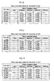
- the data tables are different for the different viscosities and each of the viscosity tables stores a plurality of data regarding the rotational speed, motor current and flow rate, for example, as shown in FIGS. 8 to 12 . More particularly, in the viscosity tables shown in FIGS. 8 to 12 , motor current for a plurality of predetermined rotational speeds and a plurality of flow rates are recorded. It is to be noted that, although such data tables as described above are preferable for data recording, otherwise a plurality of data sets each including four parameters of the viscosity, motor rotational speed, motor current and flow rate may be stored.
- the motor current flow rate-related data storage section 60 includes at least a first predetermined viscosity-related flow rate data storage function (in other words, first predetermined viscosity-related flow rate data table) 71 for storing a plurality of data regarding the motor current and the flow rate at a plurality of impeller rotational speeds at a first predetermined fluid viscosity, a second predetermined viscosity-related flow rate data storage function (in other words, second predetermined viscosity-related flow rate data table) 72 for storing a plurality of data regarding the motor current and the flow rate at a plurality of impeller rotational speeds at a second predetermined fluid viscosity, and a third predetermined viscosity-related flow rate data storage function (in other words, third predetermined viscosity-related flow rate data table) 73 for storing a plurality of data regarding the motor current and the flow rate at a plurality of impeller rotational speeds at a third predetermined fluid viscosity
- the motor current flow rate-related data storage section 60 preferably includes a fourth predetermined viscosity-related flow rate data storage function (in other words, fourth predetermined viscosity-related flow rate data table) 74 for storing a plurality of data regarding the motor current and the flow rate at a plurality of impeller rotational speeds at a fourth predetermined fluid viscosity as in the present embodiment shown.
- the motor current flow rate-related data storage section 60 preferably includes a fifth predetermined viscosity-related flow rate data storage function (in other words, fifth predetermined viscosity-related flow rate data table) 75 for storing a plurality of data regarding the motor current and the flow rate at a plurality of impeller rotational speeds at a fifth predetermined fluid viscosity.
- the centrifugal fluid pump assembly 1 of the present embodiment includes first to fifth predetermined viscosity-related flow rate data tables 71 to 75.
- the pump assembly 1 may further include a sixth or further predetermined viscosity-related flow rate data tables.
- the tables for different viscosity (mPa ⁇ s) different by an equal interval like 1, 2, 3, 4 and 5 are preferably provided, as shown in FIGS. 8 to 12 .
- the data in the data tables were obtained in advance using fluid having a specific gravity of 1. Therefore, upon calculation of the flow rate, where the measured or calculated specific gravity is not equal to 1, a value obtained by dividing the measured current by the specific gravity is used.
- the data stored in the predetermined viscosity-related flow rate data storage functions preferably include a plurality of data regarding the motor current and the flow rate at a plurality of equal impeller rotational speeds.
- the flow rate calculating section 58 uses the data stored in the viscosity rotational speed motor current flow rate-related data storage section 60, a viscosity value inputted to the fluid viscosity-related measurement data inputting section (blood parameter inputting section) 57 or a fluid viscosity value calculated from fluid measurement data (particularly, a hematocrit value) inputted to the fluid viscosity-related measurement data inputting section (blood parameter inputting section) 57, an impeller rotational speed value obtained by the impeller rotational speed measurement function or the impeller rotational speed calculation function and a measured motor current obtained by the motor current measurement function to calculate the fluid flow rate at the fluidity viscosity value, the measured motor current and the impeller rotational speed value.
- the flow rate calculating section 58 calculates the flow rate using the data of two predetermined viscosity-related flow rate data storage functions proximate to an inputted viscosity value or a fluid viscosity value calculated from inputted fluid measurement data (particularly, a hematocrit value). Further, if the inputted viscosity value or the fluid viscosity value calculated from inputted fluid measurement data (particularly, a hematocrit value) is equal to a predetermined viscosity of one of the predetermined viscosity-related flow rate data storage functions, then the flow rate calculating section 58 calculates the flow rate using the data of the predetermined viscosity-related flow rate data storage function.
- the flow rate calculating section 58 calculates the flow rate using those of the motor current flow rate relation data which relate to two impeller rotational speeds proximate to the impeller rotational speed value in data of two predetermined viscosity-related flow rate data storage functions proximate to an inputted viscosity value or a fluid viscosity value calculated from inputted fluid measurement data (particularly, a hematocrit value).
- the flow rate calculating section 58 calculates the flow rate through step calculating. Therefore, the flow rate calculating section 58 has a function for producing several flow rates for calculation before calculation of a final flow rate and calculates a flow rate in object conditions from a plurality of thus produced calculating flow rates.
- the flow rate calculating section 58 uses those of the motor current flow rate-related data which relate to two impeller rotational speeds proximate to the impeller rotational speed value in data of two predetermined viscosity-related flow rate data storage functions proximate to the inputted viscosity value or the fluid viscosity value calculated from inputted fluid measurement data (particularly, a hematocrit value) (in other words, those two predetermined viscosity-related flow rate data tables whose fluid viscosities are proximate to the fluid viscosity value), and has a first calculating flow rate production function for using two those, which are proximate to the measured motor current, of the motor current flow rate-related data relating to one of the impeller rotational speed in one of the predetermined viscosity-related flow rate data to calculate the flow rate at the measured motor current through proportional calculation or in accordance with a regression expression calculated from the two motor current flow rate-related data or adopt, where the motor current flow rate-related data include stored flow rate data regarding
- the flow rate calculating section 58 has a second calculating flow rate production function for using two those, which are proximate to the measured motor current, of the motor current flow rate-related data relating to the other impeller rotational speed in the one predetermined viscosity-related flow rate data to calculate the flow rate at the measured motor current through proportional calculation or in accordance with a regression expression calculated from the two motor current flow rate-related data or adopt, where the motor current flow rate-related data include stored flow rate data regarding a motor current equal to the measured motor current, the flow rate data.
- the second calculating flow rate production function is different from the first calculating flow rate production function only in that, while the first calculating flow rate production function uses motor current flow rate-related data regarding one of the impeller rotational speed proximate to the impeller rotational speed value in one of the predetermined viscosity-related flow rate data, the second calculating flow rate production function uses motor current flow rate-related data regarding the other impeller rotational speed proximate to the impeller rotational speed value in the one predetermined viscosity-related flow rate data.
- the flow rate calculating section 58 has a third calculating flow rate production function for using two those, which are proximate to the measured motor current, of the motor current flow rate-related data relating to the one impeller rotational speed in the other predetermined viscosity-related flow rate data to calculate the flow rate at the measured motor current through proportional calculation or in accordance with a regression expression calculated from the two motor current flow rate-related data or adopt, where the motor current flow rate-related data include stored flow rate data regarding a motor current value to the measured motor current, the flow rate data.
- the third calculating flow rate production function is different from the first calculating flow rate production function only in that, while the first calculating flow rate production function uses motor current flow rate-related data regarding one of the impeller rotational speed proximate to the impeller rotational speed value in one of the predetermined viscosity-related flow rate data, the third calculating flow rate production function uses motor current flow rate-related data regarding the one impeller rotational speed proximate to the impeller rotational speed value in the other predetermined viscosity-related flow rate data.
- the flow rate calculating section 58 has a fourth calculating flow rate production function for using two those, which are proximate to the measured motor current, of the motor current flow rate-related data relating to said other impeller rotational speed in said other predetermined viscosity-related flow rate data to calculate the flow rate at the measured motor current through proportional calculation or in accordance with a regression expression calculated from the two motor current flow rate-related data or adopt, where the motor current flow rate-related data include stored flow rate data regarding a motor current equal to the measured motor current, the flow rate data.
- the fourth calculating flow rate production function is different from the first calculating flow rate production function described hereinabove only in that, while the first calculating flow rate production function uses motor current flow rate-related data regarding one of the impeller rotational speed proximate to the impeller rotational speed value in one of the predetermined viscosity-related flow rate data, the fourth calculating flow rate production function uses motor current flow rate-related data regarding said other impeller rotational speed proximate to the impeller rotational speed value in said other predetermined viscosity-related flow rate data.
- the first to fourth calculating flow rate production functions use data of two predetermined viscosity-related flow rate data storage functions proximate to the inputted viscosity value or the fluid viscosity value calculated from inputted fluid measurement data (particularly a hematocrit value) (in other words, two predetermined viscosity-related data tables whose fluid viscosities are proximate to the fluid viscosity value).
- production of each calculating flow rate is performed using data of two ones of the predetermined viscosity-related data tables including a predetermined viscosity-related data table for a fluid viscosity lower than and most proximate to the fluid viscosity value and another predetermined viscosity-related data table for another fluid viscosity higher than and most proximate to the fluid viscosity value. It is to be noted that, where the fluid viscosity value is lower than the lowest one or higher than the highest one of the predetermined viscosity of the stored predetermined viscosity-related data tables, production of each calculating flow rate is performed using the data of two proximate ones of the predetermined viscosity-related data tables.
- production of each calculating flow rate is performed using motor current flow rate-related data regarding two impeller rotational speeds in the predetermined viscosity-related flow rate data tables which are proximate to the impeller rotational speed value.
- production of each calculating flow rate is performed using data of two impeller rotational speeds including data regarding the impeller rotational speed lower than and most proximate to the impeller rotational speed value and data regarding the impeller rotational speed higher than and most proximate to the impeller rotational speed value.
- impeller rotational speed value is lower than the lowest one or higher than the highest one of the impeller rotational speeds of the stored predetermined impeller rotational speed data
- production of each calculating flow rate is performed using the data of two proximate ones of the impeller rotational speed values.
- each calculating flow rate is performed using the two motor current flow rate-related data through proportional calculation or in accordance with a regression expression calculated from the two motor current flow rate-related data.
- production of each calculating flow rate is performed using the two motor current flow rate-related data proximate to the measured motor current through proportional calculation or in accordance with a regression expression calculated from the two motor current flow rate-related data.
- the motor current flow rate-related data include stored flow rate data regarding a motor current equal to the measured motor current
- the flow rate data is adopted as the first calculating flow rate. In this instance, no calculation is performed, but merely selective adoption is performed.
- the flow rate calculating section 58 calculates the flow rate at the fluid viscosity value, the impeller rotational speed value and the measured motor current using the first to fourth calculating flow rates calculated by the first to fourth calculating flow rate production functions. It is to be noted that the calculating flow rate produced directly from the stored data described above can be represented as primary calculating flow rate. Then, the centrifugal fluid pump assembly of the present embodiment calculates two secondary calculating flow rates using the primary calculating flow rates and calculates a final flow rate using the two secondary calculating flow rates.
- the flow rate calculating section 58 includes a fifth calculating flow rate production function for using the first calculating flow rate regarding the one predetermined viscosities and the third calculating flow rate regarding the other predetermined viscosity to calculate a flow rate at the one impeller rotational speed at the fluid viscosity value through proportional calculation or in accordance with a regression expression calculated from the two calculating flow rate values.
- the flow rate calculating section 58 further includes a sixth calculating flow rate production function for using the second calculating flow rate regarding the one predetermined viscosity and the fourth calculating flow rate regarding said other predetermined viscosity to calculate a flow rate at said other impeller rotational speed at the fluid viscosity value through proportional calculation or in accordance with a regression expression calculated from the two calculating flow rate values.
- the flow rate calculating section 58 includes a function for using the fifth and sixth calculating flow rates produced by the fifth calculating flow rate production function regarding the one impeller rotational speed and the sixth calculating flow rate production function regarding said other impeller rotational speed to calculate the flow rate at the impeller rotational speed through proportional calculation or in accordance with a regression expression calculated from the two calculating flow rates.
- the viscosity is represented by v, the rotational speed by n, the flow rate by q, and the motor current by i.
- m is varied to determine j which satisfies V j ⁇ v ⁇ 0 ⁇ V j + 1
- k which satisfies N k ⁇ n ⁇ 0 ⁇ N k + 1 is determined. Consequently, the four adjacent data points are given by V j ⁇ N k , V j + 1 ⁇ N k , V j ⁇ N k + 1 , V j + 1 ⁇ N k + 1
- a relationship between the flow rate and the motor current in the four conditions given above is determined.
- FIG. 7 a process of determination of the flow rate in the conditions of a viscosity value of 3.8 [mPa ⁇ s], a rotational speed of 1950 [rpm] and a motor current of 0.28 [A] (value obtained by dividing the actually measured current of 0.3 A by the specific gravity of 1.07) is illustrated in FIG. 7 .
- the calculation process is such as given below.
- the following four data points are adjacent data points to 3.8 mPa ⁇ s, 1950 rpm.
- the flow rate is calculated from the characteristic of the "current and flow rate" at totaling eight points including:
- the rotational speed of 1800 rpm and the motor current of 0.28A is calculated from (0.27 A, 5 L/min : x1, y1), (0.31 A, 6 L/min : x2, y2) at 1800 rpm of the data table for the viscosity of 3 mPa ⁇ s of FIG. 10 , then ((0.28 A), 3 mPa ⁇ s, 5.25 L/min : xa, ya) is obtained.
- the first calculating flow rate is calculated.
- the rotational speed of 1800 rpm and the motor current of 0.28A is calculated from (0.27 A, 4 L/min : x5, y5), (0.30 A, 5 L/min : x6, y6) at 1800 rpm of the data table for the viscosity of 4 mPa s of FIG. 11 , then ((0.28 A), 4 mPa ⁇ s, 4.33 L/min : xc, yc) is obtained.
- the third calculating flow rate is calculated.
- the flow rate at 3.8 mPa ⁇ s since what is to be determined is the flow rate at 3.8 mPa ⁇ s, if the first calculating flow rate (3 mPa ⁇ s, 5.25 L/min : xa, ya) and the third calculating flow rate (4 mPa ⁇ s, 4.33 L/min : xc, yc) are used to calculate the flow rate at the viscosity value of 3.8 mPa ⁇ s, the rotational speed of 1800 rpm and the motor current of 0.28A, then ((3.8 mPa ⁇ s, 0.28 A), 1800 rpm, 4.51 L/min : xe, ye). Thus, the fifth calculating flow rate is calculated.
- the calculation of the fifth and sixth calculating flow rates (secondary calculating flow rates) and the calculation of the flow rate described above by the flow rate calculating section may otherwise be such as described below.
- the flow rate calculating section 58 in this instance has a fifth calculating flow rate production function for using the first calculating flow rate value relating to one of the predetermined viscosity and the second calculating flow rate relating to the one predetermined viscosity to calculate the flow rate at the impeller rotational speed value at the one predetermined viscosity through proportional calculation or in accordance with a regression expression calculated from the two calculating flow rates.
- the flow rate calculating section 58 further has a sixth calculating flow rate production function for using the third calculating flow rate relating to the other predetermined viscosity and the fourth calculating flow rate relating to the other predetermined viscosity to calculate the flow rate at the impeller rotational speed value at the other predetermined viscosity through proportional calculation or in accordance with a regression expression calculated from the two calculating flow rates.
- the flow rate calculating section 58 has a function for using the fifth and sixth calculating flow rates produced by the fifth calculating flow rate production function regarding the one predetermined viscosity and the sixth calculating flow rate production function regarding the other predetermined viscosity to calculate the flow rate at the fluid viscosity value through proportional calculation or in accordance with a regression expression calculated from the two calculating flow rates.
- the calculation of the flow rate is not limited to the calculating method described above, but the flow rate may otherwise be calculated by calculating the flow rate at the viscosity of 3 mPa ⁇ s, the rotational speed of 1950 rpm and the motor current of 0.28 A using the first calculating flow rate and the second calculating flow rate to calculate the fifth calculating flow rate, calculating the flow rate at the viscosity of 4 mPa ⁇ s, the rotational speed of 1950 rpm and the motor current of 0.28 A using the third calculating flow rate and the fourth calculating flow rate to calculate the sixth calculating flow rate and then finally calculating the flow rate at the viscosity of 3.8 mPa ⁇ s as indicated by broken lines in FIG. 7 .
- the present calculating method of the flow rate similarly includes (1) selection of calculating utilization data and (2) production of first to fourth calculating flow rates (production of primary calculating flow rates) described above.
- the flow rate at 1950 rpm Since what is to be determined is the flow rate at 1950 rpm, if the first calculating flow rate (1800 rpm, 5.25 L/min : xa, ya) and the second calculating flow rate (2000 rpm, 3.33 L/min : xb, yb) are used to calculate the flow rate at the viscosity value of 3 mPa ⁇ s, the rotational speed of 1950 rpm and the motor current of 0.28A, then ((1950 rpm, 0.28 A), 3 mPa ⁇ s, 3.81 L/min : xe, ye) is obtained. Thus, the fifth calculating flow rate is calculated.
- the centrifugal fluid pump assembly of the particular embodiment described above since the flow rate can be calculated through repetitions of a simple subroutine including the proportional calculation or the linear approximation (in other words, linear regression expression), the data capacity and the storage capacity for expressions for calculation and so forth can be reduced and also the calculating processing is facilitated. Consequently, the centrifugal fluid pump assembly can be incorporated even into a portable controller and also facilitates display on the real time basis.
- the flow rate calculated by the flow rate calculating section is displayed on the display section 59.
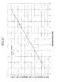
- FIG. 13 An example of the relationship between the indirect measurement flow rate obtained using the method described above and the actual flow rate is illustrated in FIG. 13 .
- FIG. 13 although a plurality of indirect measurement flow rates are indicated for each actual flow rate, they coincide almost with the latter.
- the accuracy in the proximity of a measurement point is high, and therefore, the error between them at the measurement point is very small.
- the present method is essentially linear approximation, it can be recognized readily that an estimated value between any two measurement points falls on the straight line and a high correlation is exhibited.
- FIG. 14 a relationship between the indirect measurement flow rate where the relational expression (1) given hereinabove is used for the same data and the actual flow rate is shown in FIG. 14 . Also in FIG. 14 , a plurality of indirect measurement flow rates are found for each actual flow rate, but they do not coincide very much with the latter. In particular, the difference between them directly represents the error.
- the indirect measurement flow rate can be determined similarly by extending (extrapolation) the straight line individually in the nearest intervals: V 4 ⁇ V 5 N 7 ⁇ N 8
- the countermeasure through extrapolation described above can be applied similarly.
- the centrifugal pump assembly 100 of the present embodiment includes a centrifugal fluid pump assembly body including a centrifugal fluid pump assembly body section 5 and a control mechanism (in other words, controller) 6 electrically connected to the centrifugal fluid pump assembly body section 5, and a flow rate calculating section 7 separate from the centrifugal fluid pump assembly body.
- the control mechanism 6 and the flow rate calculating section 7 have a communication function 8 so that data can be communicated therebetween.
- the communication function 8 includes a control mechanism side communication interface 81 (controller side communication interface) and a flow rate calculator side communication interface 82.
- control mechanism side communication interface 81 (controller side communication interface) has a function of originating a motor current or a signal relating to the motor current value
- the flow rate calculator communication interface 82 has a function of receiving the motor current value or the signal relating to the motor current value originated from the control mechanism side communication interface 81.
- the communication between them may be any analog communication and digital communication.
- a known communication interface can be used as the communication form.
- the centrifugal fluid pump assembly 100 of the present embodiment is different from the centrifugal fluid pump assembly 1 described hereinabove only in that the flow rate calculator is separate from the control mechanism, but is common in the configuration of the other part to that of the centrifugal fluid pump assembly 1 described above.
- the control mechanism 6 in the centrifugal fluid pump assembly 100 of the present embodiment includes, as shown in FIG. 6 , a power amplifier 52 and a motor control circuit 53 for the motor 34 for magnetic coupling, a power amplifier 54 for the electromagnets 41, a sensor circuit or sensor output monitoring section 55 for monitoring outputs of the sensor 42, a control section 51, a power supply section 56, and a control mechanism side communication interface 81.
- the control section 51 has a motor current monitoring function.
- the flow rate calculating section 7 includes a fluid measurement data inputting section (in other words, blood parameter inputting section) 57, a flow rate calculating section 58, a display section 59, a motor current flow rate-related data storage section (in other words, viscosity rotational speed motor current flow rate-related data storage section) 60, a power supply section 62, and a flow rate calculator side communication interface 82.
- the fluid measurement data inputting section (blood parameter inputting section) 57 is, for example, a fluid viscosity measurement value inputting section.
- the fluid measurement data inputting section 57 includes a blood viscosity measurement value inputting section and a specific gravity inputting section as shown in FIG. 6 .
- the blood viscosity and the specific gravity are measured with blood gathered from a user using an external instrument.
- the fluid measurement data inputting section (blood parameter inputting section) 57 may be a hematocrit value inputting section as indicated in FIG. 6 .
- the centrifugal fluid pump assembly has a viscosity calculating function for calculating the viscosity from the inputted hematocrit value.
- the flow rate calculating section 58 has a viscosity calculating function.
- a centrifugal fluid pump assembly of the present invention which includes a housing having a fluid inlet and a fluid outlet, an impeller rotatable within the housing for feeding fluid by centrifugal force upon rotation thereof, and a motor for rotating the impeller, comprises a motor current flow rate-related data storage section for storing, for a plurality of different predetermined viscosities, predetermined viscosity-related flow rate data formed from a plurality of motor current flow rate relation data at a plurality of different impeller rotational speeds at predetermined fluid viscosity, a fluid measurement data inputting section, an impeller rotational speed measurement function or an impeller rotational speed calculation function, a motor current measurement function, and a flow rate calculating section for calculating, using a fluid viscosity value inputted to the fluid measurement data inputting section or calculated from fluid measurement data inputted to the fluid measurement data inputting section, an impeller rotational speed value obtained by the impeller rotational speed measurement function or impeller rotational speed calculation function, a measured motor current obtained by the motor
- the fluid flow rate (discharge) can be calculated readily and with certainty without using a flow meter. Further, since minimum discrete data with which a necessary accuracy can be satisfied are stored without having a relational expression of the speed of rotation, motor current, viscosity and flow rate and those stored data which are proximate to an motor current value and so forth of an object of calculation are used to calculate the flow rate, it is possible for the centrifugal fluid pump to get more accurate flow rate than flow rate calculated with polynomial regression expression.
Landscapes
- Health & Medical Sciences (AREA)
- Engineering & Computer Science (AREA)
- Heart & Thoracic Surgery (AREA)
- Life Sciences & Earth Sciences (AREA)
- General Health & Medical Sciences (AREA)
- Anesthesiology (AREA)
- Biomedical Technology (AREA)
- Hematology (AREA)
- Cardiology (AREA)
- Animal Behavior & Ethology (AREA)
- Mechanical Engineering (AREA)
- Public Health (AREA)
- Veterinary Medicine (AREA)
- Medical Informatics (AREA)
- Control Of Non-Positive-Displacement Pumps (AREA)
- External Artificial Organs (AREA)
- Structures Of Non-Positive Displacement Pumps (AREA)
- Control Of Positive-Displacement Pumps (AREA)
Abstract
A centrifugal fluid pump assembly 1 includes a body section 5 and a control mechanism 6. The body section 5 includes a housing 20, an impeller 21 rotatable within the housing 20, and a motor 34 for rotating the impeller 21. The pump assembly 1 includes a motor current flow rate-related data storage section 60 for storing, for a plurality of different predetermined viscosities, predetermined viscosity-related flow rate data formed from a plurality of motor current flow rate relation data at a plurality of different impeller rotational speeds at predetermined fluid viscosity, a fluid measurement data inputting section 57, an impeller rotational speed measurement function, a motor current measurement function, and a flow rate calculating section 58 for using a fluid viscosity value, an impeller rotational speed value, a measured motor current and data stored in the motor current flow rate-related data storage section 60 to calculate a fluid flow rate.
Description
- This invention relates to a centrifugal fluid pump assembly for pumping a medical fluid such as blood.
- A centrifugal blood pump is one of pumps used in artificial heart units. A centrifugal blood pump includes a housing having a blood inlet and a blood outlet, and an impeller which rotate within the housing for feeding blood by centrifugal force upon rotation thereof. One of significant parameters for grasping that the blood pump functions correctly on a living organism is the flow rate. The flow rate may be measured directly using a sensor for exclusive use such as an ultrasonic flow meter. However, the direct measurement of the flow rate is inferior in terms of stable continuous monitoring for a long period of time. Further, an increase of the number of parts leads to increase the size of the apparatus. Therefore, a system is expected wherein the flow rate is measured indirectly from the motor speed (rotation speed) of the pump, electric current flowing through the motor (motor current), the viscosity and the specific gravity of blood and/or like parameters without the provision of a flow meter.
- In an indirect measurement system, the flow rate can be calculated by correcting a value calculated regarding the flow rate as a function of the motor speed and the motor current with a viscosity factor. In particular, the flow rate is calculated from the speed of rotation and the motor current of the motor which can be measured directly. In this instance, it is possible to determine a correlation between the motor speed, the motor current and the flow rate in advance and use an approximate expression calculated from the correlation. The approximate expression can be represented, for example, as the following expression (1):

- Where such a polynomial as given above is used, however, if the degree of approximation is lowered, then the accuracy basically in the overall region drops including data points (sample points used in the terminology of interpolation). On the other hand, if the degree of approximation is raised, then unnecessary oscillation which is a drawback in polynomial interpolation takes place, and also this gives rise to a drop the accuracy except data points.
- In order to prevent such a drop of the accuracy as described above, it is possible to prepare and refer to a large amount of data in a table to use a flow rate in the conditions nearest to a given motor speed and a given motor current as an estimated value. However, according to this system, an increased area for storing data is required, and an increase of processing of searching the storage area increases a load upon a controller for the pump. Thus, if the controller is a portable type, it is difficult to display the flow rate on the real time basis on the controller.
- Also where spline interpolation is used as the interpolation, there is a problem that a great amount of calculation is required although the problem of the accuracy is solved.
- It is an object of the present invention to provide a centrifugal fluid pump assembly which has a flow rate calculation function by which the fluid flow rate (discharge) can be calculated readily and with certainty without using a flow meter.
- It is another object of the present invention to provide a magnetically levitated centrifugal pump wherein minimum discrete data with which a necessary accuracy can be satisfied are stored without having a relational expression between the motor speed, motor current, viscosity and flow rate, and their stored data which are proximate to an motor current value and so forth of an object of calculation are used to calculate the flow rate.
- In accordance with the present invention, the objects described above are achieved by a centrifugal fluid pump assembly which includes a housing having a fluid inlet and a fluid outlet, an impeller rotatable within the housing for feeding fluid by centrifugal force upon rotation thereof, and a motor for rotating the impeller, including a motor current flow rate-related data storage section for storing, for a plurality of different predetermined viscosities, predetermined viscosity-related flow rate data formed from a plurality of motor current flow rate relation data at a plurality of different impeller rotational speeds at predetermined fluid viscosity, a fluid measurement data inputting section, an impeller rotational speed measurement function or an impeller rotational speed calculation function, a motor current measurement function, and a flow rate calculating section for calculation, using a fluid viscosity value inputted to the fluid measurement data inputting section or calculated from fluid measurement data inputted to the fluid measurement data inputting section, an impeller rotational speed value obtained by the impeller rotational speed measurement function or impeller rotational speed calculation function, a measured motor current obtained by the motor current measurement function and the data stored in the motor current flow rate-related data storage section, a fluid flow rate at the fluid viscosity value, the measured motor current and the impeller rotational speed value.
-
-
FIG. 1 is a block diagram of an embodiment of a centrifugal pump assembly of the present invention; -
FIG. 2 is a front elevational view of an example of a centrifugal pump assembly body section used in the centrifugal pump apparatus of the present invention; -
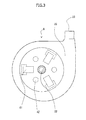
FIG. 3 is a plan view of the centrifugal pump assembly body section shown inFIG. 2 ; -
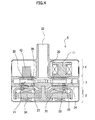
FIG. 4 is a vertical sectional view of the centrifugal pump assembly body section of the embodiment shown inFIG. 2 ; -
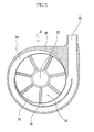
FIG. 5 is a sectional view taken along line A-A ofFIG. 2 ; -
FIG. 6 is a block diagram of another embodiment of the centrifugal pump assembly of the present invention; -
FIG. 7 is a diagrammatic view illustrating a data structure and a flow rate calculating procedure of a motor current flow rate-related data storage section; -
FIGS. 8 to 12 are diagrammatic views illustrating different particular examples of a predetermined viscosity-related data table stored in the motor current flow rate-related data storage section; -
FIG. 13 is a graph illustrating a result of calculation of the flow rate in the centrifugal fluid pump assembly of the embodiment of the present invention; and -
FIG. 14 is a graph illustrating a result of calculation of the flow rate in a centrifugal fluid pump assembly of a comparative example. - A centrifugal fluid pump assembly of the present invention is described in connection with preferred embodiments wherein it is applied to a blood pump.
- The centrifugal
fluid pump assembly 1 of the present invention includes ahousing 20 having afluid inlet 22 and afluid outlet 23, animpeller 21 rotatable within thehousing 20 for feeding fluid by centrifugal force upon rotation thereof, and amotor 34 for rotating theimpeller 21. - The centrifugal
fluid pump assembly 1 further includes a motor current flow rate-related data storage section (in other words, viscosity rotational speed motor current flow rate-related data storage section, also in other words, relational data between flow rate and motor current storage section) 60 for storing, for a plurality of different predetermined fluid viscosities (in other words, some different fixed viscosities), predetermined (or fixed) viscosity-related flow rate data formed from a plurality of motor current flow rate-related data (in other words, relational data between flow rate and motor current) at a plurality of different impeller rotational speeds (in other words, some different fixed impeller rotational speeds) at predetermined (or fixed) fluid viscosity, a fluid measurement data inputting section (in other words, fluid viscosity-related measurement data inputting section) 57, an impeller rotational speed measurement function or an impeller rotational speed calculation function, a motor current measurement function, and a flowrate calculating section 58 for using a fluid viscosity value inputted to the fluid measurement data inputting function or calculated from a fluid measurement data inputted to the fluid measurement data inputting function, an impeller rotational speed value obtained by the impeller rotational speed measurement function or impeller rotational speed calculation function, a measured motor current obtained by the motor current measurement function and the data stored in the motor current flow rate-relateddata storage section 60 to calculate the fluid flow rate at the fluid viscosity value, the measured motor current and the impeller rotational speed value. - Since the flow rate is calculated using the data stored in the motor current flow rate-related
data storage section 60 which stores, for a plurality of different predetermined viscosities (some different fixed viscosities), predetermined viscosity-related flow rate data formed from a plurality of motor current flow rate-related data at a plurality of different impeller rotational speeds at predetermined fluid viscosity in this manner, the fluid flow rate (discharge) can be calculated readily and with certainty without using a flow meter. Further, the fluid flow rate (discharge) can be calculated more quickly than where a high degree calculating expression is used for the calculation. - Further, the fluid pump assembly of the embodiment shown in
FIGS. 1 to 5 includes a centrifugal fluid pump section 2a includinghousing 20 having afluid inlet 22 and afluid outlet 23 and animpeller 21 havingmagnetic members 25 provided in the inside thereof and rotatable within thehousing 20 for feeding fluid by centrifugal force upon rotation thereof, an impeller rotatingtorque generation section 3 including arotor 31 includingmagnets 33 for attracting themagnetic members 25 of theimpeller 21 of the centrifugalfluid pump section 2 and amotor 34 for rotating therotor 31, and a impellerposition control section 4 including anelectromagnet 41. In the fluid pump assembly, theimpeller 21 rotates in a non-contacting relationship with thehousing 20. - It is to be noted that the centrifugal blood pump assembly of the present invention can be applied not only to such an apparatus of the type wherein the impeller rotates in a non-contacting relationship as described above, but also to an apparatus of the type wherein, for example, the impeller is connected to a shaft of a motor so that it is rotated by rotation of the motor.
- As shown in
FIGS. 2 to 6 , a centrifugal fluid pumpassembly body section 5 in the present embodiment includes ahousing 20 having afluid inlet 22 and afluid outlet 23, a centrifugalfluid pump section 2 having animpeller 21 rotatable within thehousing 20 for feeding blood by centrifugal force upon rotation thereof, an impeller rotating torque generation section (uncontrolled magnetic bearing section) 3 for theimpeller 21, and an impeller position control section (controlled magnetic bearing section) 4 for theimpeller 21. - Referring to
FIG. 4 , theimpeller 21 is held at a predetermined position in thehousing 20 and normally rotates without contacting with an inner face of thehousing 20 by an action of the uncontrolledmagnetic bearing section 3 and the controlledmagnetic bearing section 4. - The
housing 20 has afluid inlet 22 and afluid outlet 23 and is formed from a nonmagnetic material. Thehousing 20 has ablood chamber 24 formed therein for communication with thefluid inlet 22 and thefluid outlet 23. Theimpeller 21 is accommodated in thehousing 20. Thefluid inlet 22 is provided such that it projects substantially vertically from a central portion of an upper face of thehousing 20. Thefluid outlet 23 is provided such that it projects in a tangential direction from a side face of thehousing 20 formed in a substantially cylindrical shape as shown inFIGS. 3 and5 . - Referring to
FIG. 5 , theimpeller 21 in the form of a disk having a through-hole formed at the center thereof is accommodated in theblood chamber 24 formed in thehousing 20. Referring toFIG. 4 , theimpeller 21 has a doughnut-shaped plate member (lower shroud) 27 which forms the bottom wall, another doughnut-shaped plate member (upper shroud) 28 which forms the top wall and is open at the center thereof, and a plurality of (for example, seven)vanes 18 formed between the doughnut-shaped plate member 27 and the doughnut-shaped plate member 28. A plurality of (seven)blood passages 26 partitioned by adjacent ones of thevanes 18 are formed between thelower shroud 27 and theupper shroud 28. Theblood passages 26 are communicated with the central opening of theimpeller 21 as shown inFIG. 5 and extend from the central opening of theimpeller 21 such that the width thereof increases gradually to the outer circumferential edge of theimpeller 21. In other words, thevanes 18 are formed between adjacent ones of theblood passages 26. It is to be noted that, in the present embodiment, theblood passages 26 and thevanes 18 are provided at equal angle and in substantially same shapes. - Referring to
FIG. 4 , theimpeller 21 has a plurality of (for example, 24) first magnetic members 25 (permanent magnets, driven magnets) embedded therein. In the present embodiment, the firstmagnetic members 25 are embedded in thelower shroud 27. The embedded magnetic members 25 (permanent magnets) are provided so as to be attracted by thepermanent magnets 33 provided on therotor 31 of the impeller rotatingtorque generation section 3, which is hereinafter described, to urge theimpeller 21 away from theinlet 22 thereby to transmit rotating torque from the impeller rotating torque generation section. - Further, where a suitable number of
magnetic members 25 are embedded as in the present embodiment, also the magnetic coupling to therotor 31 hereinafter described can be secured sufficiently. The magnetic members 25 (permanent magnets) preferably have a circular shape. Or, themagnetic members 25 may be formed by dividing a ring-shaped magnet into multiple poles (for example, 24 poles), or in other words, formed from a plurality of small magnets arranged in a ring-shape such that they have magnetic poles arranged alternately. - The
impeller 21 further includes a secondmagnetic member 28 formed as the upper shroud itself or provided in the upper shroud. In the present embodiment, the entire upper shroud is formed from themagnetic member 28. Themagnetic member 28 is provided to attract theimpeller 21 toward thefluid inlet 22 by theelectromagnet 41 of the impeller position control section hereinafter described. Magnetic stainless steel or a like material is used for themagnetic member 28. - A contactless magnetic bearing is formed from the impeller
position control section 4 and the impeller rotatingtorque generation section 3, and theimpeller 21 is attracted in the opposite directions by the impellerposition control section 4 and the impeller rotatingtorque generation section 3 such that it rotates in a non-contacting relationship within thehousing 20 stably at a suitable position at which it does not contact with the inner face of thehousing 20. - Referring to
FIG. 4 , the impeller rotatingtorque generation section 3 includes arotor 31 accommodated in thehousing 20 and amotor 34 for rotating therotor 31. Therotor 31 includes a plurality ofpermanent magnets 33 provided on a face thereof adjacent the centrifugalfluid pump section 2. The center of therotor 31 is secured to a rotary shaft of themotor 34. Thepermanent magnets 33 are provided at equal angle so as to correspond to the arrangement form (quantity and arrangement positions) of thepermanent magnets 25 of theimpeller 21. - The impeller rotating
torque generation section 3 need not necessarily include such a rotor and a motor as described above, but may otherwise include, for example, a plurality of stator coils for attracting thepermanent magnets 25 of theimpeller 21 and driving theimpeller 21 to rotate. - Referring to
FIGS. 3 and4 , the impellerposition control section 4 includes a plurality of fixedelectromagnets 41 for attracting themagnetic member 28 of theimpeller 21, and aposition sensor 42 for detecting the position of themagnetic member 28 of theimpeller 21. More particularly, the impellerposition control section 4 includes a plurality ofelectromagnets 41 accommodated in thehousing 20, and a plurality ofposition sensors 42. The a plurality of (three)electromagnets 41 and the a plurality of (three)position sensors 42 of the impellerposition control section 4 are individually provided at equal angle, and also theelectromagnets 41 and theposition sensors 42 are provided at equal angle. Theelectromagnets 41 are each formed from an iron core and a coil. The number of theelectromagnets 41 in the present embodiment is three. The number of theelectromagnet 41 may be three or more, for example, four. By providing three ormore electromagnets 41 and adjusting the electromagnetic force of them using a detection result of theposition sensors 42, the force components of the rotation axis (z-axis) of theimpeller 21 can be balanced with each other and the moments around the x-axis and the y-axis perpendicular to the rotary shaft (z-axis) can be controlled. - The
position sensors 42 detect the distance between theelectromagnets 41 and themagnetic member 28, and detection outputs of theposition sensors 42 are sent to acontrol section 51 of a control mechanism (in other words, controller) 6 for controlling the current or voltage to be applied to the coil of each of theelectromagnets 41. Further, even if force in a radial direction originating from the force of gravity or the like acts upon theimpeller 21, since shearing force of magnetic fluxes between themagnetic members 25 of theimpeller 21 and themagnets 33 of therotor 31 and shearing force between theelectromagnets 41 and themagnetic member 28 act, theimpeller 21 is kept at the center of thehousing 20. - Referring to
FIG. 1 , thecontrol mechanism 6 includes apower amplifier 52 and amotor control circuit 53 for themotor 34 for magnetic coupling, apower amplifier 54 for theelectromagnets 41, asensor circuit 55 for theposition sensors 42, a sensor output monitoring section (not shown) for monitoring the sensor outputs, acontrol section 51, apower supply section 56, a fluid measurement data inputting section (in other words, blood parameter inputting section) 57, a flowrate calculating section 58, adisplay section 59, and a motor current flow rate-related data storage section (in other words, viscosity rotational speed motor current flow rate-related data storage section) 60. Thecontrol section 51 has a motor current monitoring function. - The fluid measurement data inputting section (blood parameter inputting section) 57 is, for example, a fluid viscosity measurement value inputting section. Preferably, the fluid measurement data inputting section (blood parameter inputting section) 57 includes a blood viscosity measurement value inputting section and a specific gravity inputting section as shown in
FIG. 1 . In this instance, the blood viscosity and the specific gravity are measured with blood gathered from a patient using an external instrument. - The fluid measurement data inputting section (blood parameter inputting section) 57 may be, for example, a hematocrit value inputting section as indicated in
FIG. 1 . In this instance, the centrifugal fluid pump assembly has a viscosity calculating function for calculation the viscosity from the inputted hematocrit value. In short, the flowrate calculating section 58 is provided with a viscosity calculating function. The viscosity calculating method is given by the following expression:
where V [mPa·s] is the viscosity, Hct [%] is the hematocrit value, and a0 to a3 are coefficients. - Further, the centrifugal fluid pump assembly preferably has a specific gravity calculating function for calculating the specific gravity from the inputted hematocrit value. In short, the flow
rate calculating section 58 is provided with a specific gravity calculating function. The specific gravity calculation method is represented by the following expression:
where p is the specific gravity, Hct [%] is the hematocrit value, and bo to b3 are coefficients. - Preferably, the centrifugal fluid pump apparatus has a measured motor current correcting function for correcting a motor current actual measurement value with the inputted or calculated specific gravity to obtain a measured motor current. More particularly, the motor current actual measurement value is corrected in accordance with the following expression:

- Now, the flow rate calculating function of the flow rate calculating section is described.
- The viscosity rotational speed motor current flow rate-related
data storage section 60 of thecontrol mechanism 6 stores, for a plurality of predetermined viscosities, predetermined viscosity-related flow rate data formed from a plurality of motor current flow rate-related data at a plurality of different impeller rotational speeds at predetermined fluid viscosity. More particularly, the viscosity rotational speed motor current flow rate-relateddata storage section 60 stores data for a plurality of different viscosities in the form of data tables each for a viscosity. In other words, the viscosity rotational speed motor current flow rate-relateddata storage section 60 stores a database regarding the viscosity, impeller rotational speed, motor current and flow rate. The data tables are different for the different viscosities and each of the viscosity tables stores a plurality of data regarding the rotational speed, motor current and flow rate, for example, as shown inFIGS. 8 to 12 . More particularly, in the viscosity tables shown inFIGS. 8 to 12 , motor current for a plurality of predetermined rotational speeds and a plurality of flow rates are recorded. It is to be noted that, although such data tables as described above are preferable for data recording, otherwise a plurality of data sets each including four parameters of the viscosity, motor rotational speed, motor current and flow rate may be stored. - More specifically, referring to
FIG. 7 , the motor current flow rate-relateddata storage section 60 includes at least a first predetermined viscosity-related flow rate data storage function (in other words, first predetermined viscosity-related flow rate data table) 71 for storing a plurality of data regarding the motor current and the flow rate at a plurality of impeller rotational speeds at a first predetermined fluid viscosity, a second predetermined viscosity-related flow rate data storage function (in other words, second predetermined viscosity-related flow rate data table) 72 for storing a plurality of data regarding the motor current and the flow rate at a plurality of impeller rotational speeds at a second predetermined fluid viscosity, and a third predetermined viscosity-related flow rate data storage function (in other words, third predetermined viscosity-related flow rate data table) 73 for storing a plurality of data regarding the motor current and the flow rate at a plurality of impeller rotational speeds at a third predetermined fluid viscosity. Particularly, the motor current flow rate-relateddata storage section 60 preferably includes a fourth predetermined viscosity-related flow rate data storage function (in other words, fourth predetermined viscosity-related flow rate data table) 74 for storing a plurality of data regarding the motor current and the flow rate at a plurality of impeller rotational speeds at a fourth predetermined fluid viscosity as in the present embodiment shown. Furthermore, the motor current flow rate-relateddata storage section 60 preferably includes a fifth predetermined viscosity-related flow rate data storage function (in other words, fifth predetermined viscosity-related flow rate data table) 75 for storing a plurality of data regarding the motor current and the flow rate at a plurality of impeller rotational speeds at a fifth predetermined fluid viscosity. - As seen in
FIG. 7 , the centrifugalfluid pump assembly 1 of the present embodiment includes first to fifth predetermined viscosity-related flow rate data tables 71 to 75. Thepump assembly 1 may further include a sixth or further predetermined viscosity-related flow rate data tables. As the first to fifth predetermined viscosity-related flow rate data tables, the tables for different viscosity (mPa ·s) different by an equal interval like 1, 2, 3, 4 and 5 are preferably provided, as shown inFIGS. 8 to 12 . The data in the data tables were obtained in advance using fluid having a specific gravity of 1. Therefore, upon calculation of the flow rate, where the measured or calculated specific gravity is not equal to 1, a value obtained by dividing the measured current by the specific gravity is used. - The data stored in the predetermined viscosity-related flow rate data storage functions (predetermined viscosity-related data tables) preferably include a plurality of data regarding the motor current and the flow rate at a plurality of equal impeller rotational speeds.
- The flow
rate calculating section 58 uses the data stored in the viscosity rotational speed motor current flow rate-relateddata storage section 60, a viscosity value inputted to the fluid viscosity-related measurement data inputting section (blood parameter inputting section) 57 or a fluid viscosity value calculated from fluid measurement data (particularly, a hematocrit value) inputted to the fluid viscosity-related measurement data inputting section (blood parameter inputting section) 57, an impeller rotational speed value obtained by the impeller rotational speed measurement function or the impeller rotational speed calculation function and a measured motor current obtained by the motor current measurement function to calculate the fluid flow rate at the fluidity viscosity value, the measured motor current and the impeller rotational speed value. - More particularly, the flow
rate calculating section 58 calculates the flow rate using the data of two predetermined viscosity-related flow rate data storage functions proximate to an inputted viscosity value or a fluid viscosity value calculated from inputted fluid measurement data (particularly, a hematocrit value). Further, if the inputted viscosity value or the fluid viscosity value calculated from inputted fluid measurement data (particularly, a hematocrit value) is equal to a predetermined viscosity of one of the predetermined viscosity-related flow rate data storage functions, then the flowrate calculating section 58 calculates the flow rate using the data of the predetermined viscosity-related flow rate data storage function. Furthermore, the flowrate calculating section 58 calculates the flow rate using those of the motor current flow rate relation data which relate to two impeller rotational speeds proximate to the impeller rotational speed value in data of two predetermined viscosity-related flow rate data storage functions proximate to an inputted viscosity value or a fluid viscosity value calculated from inputted fluid measurement data (particularly, a hematocrit value). - Further, in the centrifugal fluid pump assembly of the present embodiment, the flow
rate calculating section 58 calculates the flow rate through step calculating. Therefore, the flowrate calculating section 58 has a function for producing several flow rates for calculation before calculation of a final flow rate and calculates a flow rate in object conditions from a plurality of thus produced calculating flow rates. - More particularly, the flow
rate calculating section 58 uses those of the motor current flow rate-related data which relate to two impeller rotational speeds proximate to the impeller rotational speed value in data of two predetermined viscosity-related flow rate data storage functions proximate to the inputted viscosity value or the fluid viscosity value calculated from inputted fluid measurement data (particularly, a hematocrit value) (in other words, those two predetermined viscosity-related flow rate data tables whose fluid viscosities are proximate to the fluid viscosity value), and has a first calculating flow rate production function for using two those, which are proximate to the measured motor current, of the motor current flow rate-related data relating to one of the impeller rotational speed in one of the predetermined viscosity-related flow rate data to calculate the flow rate at the measured motor current through proportional calculation or in accordance with a regression expression calculated from the two motor current flow rate-related data or adopt, where the motor current flow rate-related data include stored flow rate data regarding a motor current equal to the measured motor current, the flow rate data. - Further, the flow
rate calculating section 58 has a second calculating flow rate production function for using two those, which are proximate to the measured motor current, of the motor current flow rate-related data relating to the other impeller rotational speed in the one predetermined viscosity-related flow rate data to calculate the flow rate at the measured motor current through proportional calculation or in accordance with a regression expression calculated from the two motor current flow rate-related data or adopt, where the motor current flow rate-related data include stored flow rate data regarding a motor current equal to the measured motor current, the flow rate data. - The second calculating flow rate production function is different from the first calculating flow rate production function only in that, while the first calculating flow rate production function uses motor current flow rate-related data regarding one of the impeller rotational speed proximate to the impeller rotational speed value in one of the predetermined viscosity-related flow rate data, the second calculating flow rate production function uses motor current flow rate-related data regarding the other impeller rotational speed proximate to the impeller rotational speed value in the one predetermined viscosity-related flow rate data.
- Further, the flow
rate calculating section 58 has a third calculating flow rate production function for using two those, which are proximate to the measured motor current, of the motor current flow rate-related data relating to the one impeller rotational speed in the other predetermined viscosity-related flow rate data to calculate the flow rate at the measured motor current through proportional calculation or in accordance with a regression expression calculated from the two motor current flow rate-related data or adopt, where the motor current flow rate-related data include stored flow rate data regarding a motor current value to the measured motor current, the flow rate data. - The third calculating flow rate production function is different from the first calculating flow rate production function only in that, while the first calculating flow rate production function uses motor current flow rate-related data regarding one of the impeller rotational speed proximate to the impeller rotational speed value in one of the predetermined viscosity-related flow rate data, the third calculating flow rate production function uses motor current flow rate-related data regarding the one impeller rotational speed proximate to the impeller rotational speed value in the other predetermined viscosity-related flow rate data.
- Further, the flow
rate calculating section 58 has a fourth calculating flow rate production function for using two those, which are proximate to the measured motor current, of the motor current flow rate-related data relating to said other impeller rotational speed in said other predetermined viscosity-related flow rate data to calculate the flow rate at the measured motor current through proportional calculation or in accordance with a regression expression calculated from the two motor current flow rate-related data or adopt, where the motor current flow rate-related data include stored flow rate data regarding a motor current equal to the measured motor current, the flow rate data. - The fourth calculating flow rate production function is different from the first calculating flow rate production function described hereinabove only in that, while the first calculating flow rate production function uses motor current flow rate-related data regarding one of the impeller rotational speed proximate to the impeller rotational speed value in one of the predetermined viscosity-related flow rate data, the fourth calculating flow rate production function uses motor current flow rate-related data regarding said other impeller rotational speed proximate to the impeller rotational speed value in said other predetermined viscosity-related flow rate data.
- The first to fourth calculating flow rate production functions use data of two predetermined viscosity-related flow rate data storage functions proximate to the inputted viscosity value or the fluid viscosity value calculated from inputted fluid measurement data (particularly a hematocrit value) (in other words, two predetermined viscosity-related data tables whose fluid viscosities are proximate to the fluid viscosity value). In particular, production of each calculating flow rate is performed using data of two ones of the predetermined viscosity-related data tables including a predetermined viscosity-related data table for a fluid viscosity lower than and most proximate to the fluid viscosity value and another predetermined viscosity-related data table for another fluid viscosity higher than and most proximate to the fluid viscosity value. It is to be noted that, where the fluid viscosity value is lower than the lowest one or higher than the highest one of the predetermined viscosity of the stored predetermined viscosity-related data tables, production of each calculating flow rate is performed using the data of two proximate ones of the predetermined viscosity-related data tables.
- Similarly, production of each calculating flow rate is performed using motor current flow rate-related data regarding two impeller rotational speeds in the predetermined viscosity-related flow rate data tables which are proximate to the impeller rotational speed value. In short, production of each calculating flow rate is performed using data of two impeller rotational speeds including data regarding the impeller rotational speed lower than and most proximate to the impeller rotational speed value and data regarding the impeller rotational speed higher than and most proximate to the impeller rotational speed value. It is to be noted that, where the impeller rotational speed value is lower than the lowest one or higher than the highest one of the impeller rotational speeds of the stored predetermined impeller rotational speed data, production of each calculating flow rate is performed using the data of two proximate ones of the impeller rotational speed values.
- Further, where motor current flow rate-related data most proximate to and lower than the measured motor current and motor current flow rate-related data most proximate to and higher than the measured motor current are present, production of each calculating flow rate is performed using the two motor current flow rate-related data through proportional calculation or in accordance with a regression expression calculated from the two motor current flow rate-related data. However, where motor current flow rate-related data most proximate to and lower than the measured motor current or motor current flow rate-related data most proximate to and higher than the measured motor current is not present, production of each calculating flow rate is performed using the two motor current flow rate-related data proximate to the measured motor current through proportional calculation or in accordance with a regression expression calculated from the two motor current flow rate-related data. On the other hand, where the motor current flow rate-related data include stored flow rate data regarding a motor current equal to the measured motor current, the flow rate data is adopted as the first calculating flow rate. In this instance, no calculation is performed, but merely selective adoption is performed.
- Then, the flow
rate calculating section 58 calculates the flow rate at the fluid viscosity value, the impeller rotational speed value and the measured motor current using the first to fourth calculating flow rates calculated by the first to fourth calculating flow rate production functions. It is to be noted that the calculating flow rate produced directly from the stored data described above can be represented as primary calculating flow rate. Then, the centrifugal fluid pump assembly of the present embodiment calculates two secondary calculating flow rates using the primary calculating flow rates and calculates a final flow rate using the two secondary calculating flow rates. - More particularly, the flow
rate calculating section 58 includes a fifth calculating flow rate production function for using the first calculating flow rate regarding the one predetermined viscosities and the third calculating flow rate regarding the other predetermined viscosity to calculate a flow rate at the one impeller rotational speed at the fluid viscosity value through proportional calculation or in accordance with a regression expression calculated from the two calculating flow rate values. - The flow
rate calculating section 58 further includes a sixth calculating flow rate production function for using the second calculating flow rate regarding the one predetermined viscosity and the fourth calculating flow rate regarding said other predetermined viscosity to calculate a flow rate at said other impeller rotational speed at the fluid viscosity value through proportional calculation or in accordance with a regression expression calculated from the two calculating flow rate values. - Further, the flow
rate calculating section 58 includes a function for using the fifth and sixth calculating flow rates produced by the fifth calculating flow rate production function regarding the one impeller rotational speed and the sixth calculating flow rate production function regarding said other impeller rotational speed to calculate the flow rate at the impeller rotational speed through proportional calculation or in accordance with a regression expression calculated from the two calculating flow rates. - More detailed description is given below.
- Motor current where the specific gravity of the fluid is 1 at flow rates
1, 2, 3, 4, 5, 6, 7, 8, 9 [L/min] - for each of rotational speeds
1200, 1400, 1600, 1800, 2000, 2200, 2400, 2600 [rpm] - at each of viscosities
1, 2, 3, 4, 5 [mPa s] - are determined through an experiment in advance. It is to be noted that, for correction where the specific gravity is not 1, the motor current value then is divided by the specific gravity to obtain a normalized value.
- Here, it is assumed that


where m is a positive integer. In the following description, the viscosity is represented by v, the rotational speed by n, the flow rate by q, and the motor current by i. - Now, it is assumed that a viscosity value v0, a rotational speed n0 and a motor current i0 are given and it is intended to determine the flow rate then (since the viscosity and the specific gravity do not vary significantly with the same person although they differ depending upon individual differences of patients, if they are measured by periodical inspections, then a sufficient accuracy is obtained).
- First, four adjacent data points (points at which the relationship between the flow rate and the motor current is determined through a measurement in advance) to this point (v0, nO) are determined.
- In particular, m is varied to determine j which satisfies

Also with regard to the rotational speed, k which satisfies
is determined. Consequently, the four adjacent data points are given by
A relationship between the flow rate and the motor current in the four conditions given above is determined. In particular, since
data points:
are present, m which satisfies
is determined. Then, using linear approximation for the interval [Qm, Qm+1] (data points are measured at intervals with which a necessary accuracy is obtained through linear approximation in advance), the relational expression of (q, i) is
and therefore, - q00: flow rate (calculated value) at (Vj, Nk, i0)
- q10: flow rate (calculated value) at (Vj+i, Nk, i0)
- q01: flow rate (calculated value) at (Vj, Nk+1, i0)
- q11: flow rate (calculated value) at (Vj+i, Nk+1, i0)
- From (Vj, q00) and (Vj+1, q10) where Nk and i0 are equal, using linear approximation in the interval [Vj, Vj+1], the relational expression of (v, q) is given by

and therefore, if the flow rate at v0 is represented by q20, then it is given by
Similarly, from (Vj, q01) and (Vj+1, q11) where Nk+1 and i0 are equal, if the flow rate at v0 is represented by q21, then it is given by
In particular,
q20: flow rate (calculated value) at (v0, Nk, i0)
q21: flow rate (calculated value) at (v0, Nk+1, i0)
are determined. - Then, using linear approximation in the interval [Nk, Nk+1], the relational expression of (n, q) is given by

and therefore, the flow rate q0 at (v0, n0, i0) to be determined finally is given by
- As a particular example, a process of determination of the flow rate in the conditions of a viscosity value of 3.8 [mPa ·s], a rotational speed of 1950 [rpm] and a motor current of 0.28 [A] (value obtained by dividing the actually measured current of 0.3 A by the specific gravity of 1.07) is illustrated in
FIG. 7 . The calculation process is such as given below. - The following four data points are adjacent data points to 3.8 mPa·s, 1950 rpm.
- The flow rate is calculated from the characteristic of the "current and flow rate" at totaling eight points including:
- (0.27 A, 5 L/min: x1, y1), (0.31 A, 6 L/min : x2, y2) at 1800 rpm of the data table for the viscosity of 3 mPa s of
FIG. 10 , - (0.27 A, 3 L/min: x3, y3), (0.30 A, 4 L/min: x4, y4) at 2000 rpm,
- (0.27 A, 4 L/min : x5, y5), (0.30 A, 5 L/min : x6, y6) at 1800 rpm of the data table for the viscosity of 4 mPa s of
FIG. 11 , and - (0.26 A, 2 L/min: x7, y7), (0.29 A, 3 L/min: x8, y8) at 2000 rpm.
- If the flow rate at the viscosity of 3 mPa ·s, the rotational speed of 1800 rpm and the motor current of 0.28A is calculated from (0.27 A, 5 L/min : x1, y1), (0.31 A, 6 L/min : x2, y2) at 1800 rpm of the data table for the viscosity of 3 mPa ·s of
FIG. 10 , then ((0.28 A), 3 mPa ·s, 5.25 L/min : xa, ya) is obtained. Thus, the first calculating flow rate is calculated. - Similarly, if the flow rate at the viscosity of 3 mPa ·s, the rotational speed of 2000 rpm and the motor current of 0.28A is calculated from (0.27 A, 3 L/min : x3, y3), (0.30 A, 4 L/min : x4, y4) at 2000 rpm, then ((0.28 A), 3 mPa ·s, 3.33 L/min : xb, yb) is obtained. Thus, the second calculating flow rate is calculated.
- If the flow rate at the viscosity of 4 mPa ·s, the rotational speed of 1800 rpm and the motor current of 0.28A is calculated from (0.27 A, 4 L/min : x5, y5), (0.30 A, 5 L/min : x6, y6) at 1800 rpm of the data table for the viscosity of 4 mPa s of
FIG. 11 , then ((0.28 A), 4 mPa ·s, 4.33 L/min : xc, yc) is obtained. Thus, the third calculating flow rate is calculated. - Similarly, if the flow rate at the viscosity of 4 mPa ·s, the rotational speed of 2000 rpm and the motor current of 0.28A is calculated from (0.26 A, 2 L/min : x7, y7), (0.29 A, 3 L/min : x8, y8) at 2000 rpm, then ((0.28 A), 4 mPa ·s, 2.66 L/min : xd, yd) is obtained. Thus, the fourth calculating flow rate is calculated.
- It is to be noted that, where data of a value equal to the motor current value of the object of the calculation is stored in the data tables, the value is produced as a pertaining one of the first to fourth calculating flow rates.
- Then, since what is to be determined is the flow rate at 3.8 mPa ·s, if the first calculating flow rate (3 mPa ·s, 5.25 L/min : xa, ya) and the third calculating flow rate (4 mPa ·s, 4.33 L/min : xc, yc) are used to calculate the flow rate at the viscosity value of 3.8 mPa ·s, the rotational speed of 1800 rpm and the motor current of 0.28A, then ((3.8 mPa ·s, 0.28 A), 1800 rpm, 4.51 L/min : xe, ye). Thus, the fifth calculating flow rate is calculated.
- Similarly, since what is to be determined is the flow rate at 3.8 mPa ·s, if the second calculating flow rate (3 mPa ·s, 3.33 L/min : xb, yb) and the fourth calculating flow rate (4 mPa ·s, 2.66 L/min : xd, yd) are used to calculate the flow rate at the viscosity value of 3.8 mPa ·s, the rotational speed of 2000 rpm and the motor current of 0.28A, then ((3.8 mPa ·s, 0.28 A), 2000 rpm, 2.79 L/min : xf, yf). Thus, the sixth calculating flow rate is calculated.
- Finally, since what is to be determined is the flow rate at 1950 rpm, if the fifth calculating flow rate (1800 rpm, 4.51 L/min : xe, ye) and the sixth calculating flow rate (2000 rpm, 2.79 L/min : xf, yf) are used to calculate the flow rate at the rotational speed of 1950 rpm, the motor current of 0.28A and the viscosity of 3.8 mPa ·s, then ((3.8 mPa ·s, 0.28 A), 1950 rpm, 3.22 L/min : xe, ye). Thus, the flow rate is calculated.
- The calculation of the fifth and sixth calculating flow rates (secondary calculating flow rates) and the calculation of the flow rate described above by the flow rate calculating section may otherwise be such as described below.
- The flow
rate calculating section 58 in this instance has a fifth calculating flow rate production function for using the first calculating flow rate value relating to one of the predetermined viscosity and the second calculating flow rate relating to the one predetermined viscosity to calculate the flow rate at the impeller rotational speed value at the one predetermined viscosity through proportional calculation or in accordance with a regression expression calculated from the two calculating flow rates. - The flow
rate calculating section 58 further has a sixth calculating flow rate production function for using the third calculating flow rate relating to the other predetermined viscosity and the fourth calculating flow rate relating to the other predetermined viscosity to calculate the flow rate at the impeller rotational speed value at the other predetermined viscosity through proportional calculation or in accordance with a regression expression calculated from the two calculating flow rates. - Further, the flow
rate calculating section 58 has a function for using the fifth and sixth calculating flow rates produced by the fifth calculating flow rate production function regarding the one predetermined viscosity and the sixth calculating flow rate production function regarding the other predetermined viscosity to calculate the flow rate at the fluid viscosity value through proportional calculation or in accordance with a regression expression calculated from the two calculating flow rates. - In short, the calculation of the flow rate is not limited to the calculating method described above, but the flow rate may otherwise be calculated by calculating the flow rate at the viscosity of 3 mPa ·s, the rotational speed of 1950 rpm and the motor current of 0.28 A using the first calculating flow rate and the second calculating flow rate to calculate the fifth calculating flow rate, calculating the flow rate at the viscosity of 4 mPa ·s, the rotational speed of 1950 rpm and the motor current of 0.28 A using the third calculating flow rate and the fourth calculating flow rate to calculate the sixth calculating flow rate and then finally calculating the flow rate at the viscosity of 3.8 mPa ·s as indicated by broken lines in
FIG. 7 . Detailed description is given below. It is to be noted that also the present calculating method of the flow rate similarly includes (1) selection of calculating utilization data and (2) production of first to fourth calculating flow rates (production of primary calculating flow rates) described above. - Since what is to be determined is the flow rate at 1950 rpm, if the first calculating flow rate (1800 rpm, 5.25 L/min : xa, ya) and the second calculating flow rate (2000 rpm, 3.33 L/min : xb, yb) are used to calculate the flow rate at the viscosity value of 3 mPa ·s, the rotational speed of 1950 rpm and the motor current of 0.28A, then ((1950 rpm, 0.28 A), 3 mPa ·s, 3.81 L/min : xe, ye) is obtained. Thus, the fifth calculating flow rate is calculated. Similarly, since what is to be determined is the flow rate at 1950 rpm, if the third calculating flow rate (1800 rpm, 4.33 L/min : xc, yc) and the fourth calculating flow rate (2000 rpm, 2.66 L/min : xd, yd) are used to calculate the flow rate at the viscosity value of 4 mPa ·s, the rotational speed of 1950 rpm and the motor current of 0.28A, then ((1950 rpm, 0.28 A), 4 mPa ·s, 3.08 L/min: xf, yf) is obtained. Thus, the sixth calculating flow rate is calculated.
- Finally, since what is to be determined is the flow rate at 3.8 mPa ·s, if the fifth calculating flow rate (3 mPa ·s, 3.81 L/min : xe, ye) and the sixth calculating flow rate (4 mPa ·s, 3.077 L/min : xf, yf) are used to calculate the flow rate at the rotational speed of 1950 rpm, the motor current of 0.28A and the viscosity of 3.8 mPa ·s, then ((1950 rpm, 0.28 A), 3.8 mPa ·s, 3.22 L/min : xe, ye) is obtained. Thus, the flow rate is calculated.
- With the centrifugal fluid pump assembly of the particular embodiment described above, since the flow rate can be calculated through repetitions of a simple subroutine including the proportional calculation or the linear approximation (in other words, linear regression expression), the data capacity and the storage capacity for expressions for calculation and so forth can be reduced and also the calculating processing is facilitated. Consequently, the centrifugal fluid pump assembly can be incorporated even into a portable controller and also facilitates display on the real time basis.
- The flow rate calculated by the flow rate calculating section is displayed on the
display section 59. - An example of the relationship between the indirect measurement flow rate obtained using the method described above and the actual flow rate is illustrated in
FIG. 13 . InFIG. 13 , although a plurality of indirect measurement flow rates are indicated for each actual flow rate, they coincide almost with the latter. Originally, according to the present method, the accuracy in the proximity of a measurement point is high, and therefore, the error between them at the measurement point is very small. However, since the present method is essentially linear approximation, it can be recognized readily that an estimated value between any two measurement points falls on the straight line and a high correlation is exhibited. - In contrast, a relationship between the indirect measurement flow rate where the relational expression (1) given hereinabove is used for the same data and the actual flow rate is shown in
FIG. 14 . Also inFIG. 14 , a plurality of indirect measurement flow rates are found for each actual flow rate, but they do not coincide very much with the latter. In particular, the difference between them directly represents the error. - It is to be noted that, also where the point (v0, nO) is outside the data points like, for example,


the indirect measurement flow rate can be determined similarly by extending (extrapolation) the straight line individually in the nearest intervals:

Also with regard to the relationship between the flow rate and the motor current, where given conditions are outside the data points, the countermeasure through extrapolation described above can be applied similarly. - The centrifugal pump assembly may otherwise be of such a type as shown in
FIG. 6 . Referring toFIG. 6 , thecentrifugal pump assembly 100 of the present embodiment includes a centrifugal fluid pump assembly body including a centrifugal fluid pumpassembly body section 5 and a control mechanism (in other words, controller) 6 electrically connected to the centrifugal fluid pumpassembly body section 5, and a flowrate calculating section 7 separate from the centrifugal fluid pump assembly body. Thecontrol mechanism 6 and the flowrate calculating section 7 have acommunication function 8 so that data can be communicated therebetween. In particular, thecommunication function 8 includes a control mechanism side communication interface 81 (controller side communication interface) and a flow rate calculatorside communication interface 82. At least the control mechanism side communication interface 81 (controller side communication interface) has a function of originating a motor current or a signal relating to the motor current value, and the flow ratecalculator communication interface 82 has a function of receiving the motor current value or the signal relating to the motor current value originated from the control mechanismside communication interface 81. It is to be noted that the communication between them may be any analog communication and digital communication. A known communication interface can be used as the communication form. The centrifugalfluid pump assembly 100 of the present embodiment is different from the centrifugalfluid pump assembly 1 described hereinabove only in that the flow rate calculator is separate from the control mechanism, but is common in the configuration of the other part to that of the centrifugalfluid pump assembly 1 described above. - The
control mechanism 6 in the centrifugalfluid pump assembly 100 of the present embodiment includes, as shown inFIG. 6 , apower amplifier 52 and amotor control circuit 53 for themotor 34 for magnetic coupling, apower amplifier 54 for theelectromagnets 41, a sensor circuit or sensoroutput monitoring section 55 for monitoring outputs of thesensor 42, acontrol section 51, apower supply section 56, and a control mechanismside communication interface 81. Thecontrol section 51 has a motor current monitoring function. - The flow
rate calculating section 7 includes a fluid measurement data inputting section (in other words, blood parameter inputting section) 57, a flowrate calculating section 58, adisplay section 59, a motor current flow rate-related data storage section (in other words, viscosity rotational speed motor current flow rate-related data storage section) 60, apower supply section 62, and a flow rate calculatorside communication interface 82. - The fluid measurement data inputting section (blood parameter inputting section) 57 is, for example, a fluid viscosity measurement value inputting section. Preferably, the fluid measurement
data inputting section 57 includes a blood viscosity measurement value inputting section and a specific gravity inputting section as shown inFIG. 6 . In this instance, the blood viscosity and the specific gravity are measured with blood gathered from a user using an external instrument. - The fluid measurement data inputting section (blood parameter inputting section) 57 may be a hematocrit value inputting section as indicated in
FIG. 6 . In this instance, the centrifugal fluid pump assembly has a viscosity calculating function for calculating the viscosity from the inputted hematocrit value. In short, the flowrate calculating section 58 has a viscosity calculating function. - The configuration of the other part is same as that of the embodiment described hereinabove.
- A centrifugal fluid pump assembly of the present invention which includes a housing having a fluid inlet and a fluid outlet, an impeller rotatable within the housing for feeding fluid by centrifugal force upon rotation thereof, and a motor for rotating the impeller, comprises a motor current flow rate-related data storage section for storing, for a plurality of different predetermined viscosities, predetermined viscosity-related flow rate data formed from a plurality of motor current flow rate relation data at a plurality of different impeller rotational speeds at predetermined fluid viscosity, a fluid measurement data inputting section, an impeller rotational speed measurement function or an impeller rotational speed calculation function, a motor current measurement function, and a flow rate calculating section for calculating, using a fluid viscosity value inputted to the fluid measurement data inputting section or calculated from fluid measurement data inputted to the fluid measurement data inputting section, an impeller rotational speed value obtained by the impeller rotational speed measurement function or impeller rotational speed calculation function, a measured motor current obtained by the motor current measurement function and the data stored in the motor current flow rate-related data storage section, a fluid flow rate at the fluid viscosity value, measured motor current and impeller rotational speed value.
- With the present centrifugal fluid pump assembly, the fluid flow rate (discharge) can be calculated readily and with certainty without using a flow meter. Further, since minimum discrete data with which a necessary accuracy can be satisfied are stored without having a relational expression of the speed of rotation, motor current, viscosity and flow rate and those stored data which are proximate to an motor current value and so forth of an object of calculation are used to calculate the flow rate, it is possible for the centrifugal fluid pump to get more accurate flow rate than flow rate calculated with polynomial regression expression.
- While the preferred form of the present invention has been described, it is to be understood that modifications will be apparent to those skilled in the art without departing from the spirit of the invention. The scope of the invention, therefore, is to be determined solely by the following claims.
Claims (14)
- A centrifugal blood pump assembly which includes a housing having a blood inlet and a blood outlet, an impeller rotatable within said housing for feeding blood by centrifugal force upon rotation thereof, and a motor for rotating said impeller, comprising:a motor current flow rate-related data storage section for storing, for a plurality of different predetermined viscosities, predetermined viscosity-related flow rate data formed from a plurality of motor current flow rate relation data at a plurality of different impeller rotational speeds at predetermined blood viscosity;a blood measurement data inputting section;an impeller rotational speed measurement function or an impeller rotational speed calculation function;a motor current measurement function;a flow rate calculating section for calculation, using a blood viscosity value calculated from a blood measurement data inputted to said blood measurement data inputting section, an impeller rotational speed value obtained by said impeller rotational speed measurement function or impeller rotational speed calculation function, a measured motor current obtained by said motor current measurement function and the data stored in said motor current flow rate-related data storage section, a blood flow rate at the blood viscosity value, the measured motor current and the impeller rotational speed value, andsaid blood measurement data inputting section is a hematocrit value inputting section, and said centrifugal blood pump assembly further comprises a blood viscosity value calculating function for calculating the viscosity from the inputted hematocrit value.
- A centrifugal blood pump assembly according to claim 1, comprising a centrifugal blood pump section including said housing having said blood inlet and said blood outlet and said impeller having magnetic means and rotatable within said housing, an impeller rotating torque generation section including a rotor having magnetic means for attracting said magnetic means of said impeller and said motor for rotating said rotor, and an impeller position control section including electromagnet means, and wherein said impeller rotates in a non-contacting relationship with said housing.
- A centrifugal blood pump assembly according to claim 1 or 2, wherein said centrifugal blood pump assembly further comprises a specific gravity calculating section for calculating a specific gravity from the inputted hematocrit value.
- A centrifugal blood pump assembly according to any one of claims 1 through 3, further comprising a specific gravity inputting section or specific gravity calculating function, and a measured motor current correcting function for correcting the measured motor current using a specific gravity inputted by said specific gravity inputting section or calculated by said specific value calculating function.
- A centrifugal blood pump assembly according to any one of claims 1 through 4, wherein said motor current flow rate-related data storage section includes at least a first predetermined viscosity-related flow rate data storage function for storing a plurality of data regarding the motor current and the flow rate at a plurality of impeller rotational speeds at a first predetermined blood viscosity, a second predetermined viscosity-related flow rate data storage function for storing a plurality of data regarding the motor current and the flow rate at a plurality of impeller rotational speeds at a second predetermined blood viscosity, and a third predetermined viscosity-related flow rate data storage function for storing a plurality of data regarding the motor current and the flow rate at a plurality of impeller rotational speeds at a third predetermined blood viscosity.
- A centrifugal blood pump assembly according to claim 5, wherein said motor current flow rate-related data storage section further includes a fourth predetermined viscosity-related flow rate data storage function for storing a plurality of data regarding the motor current and the flow rate at a plurality of impeller rotational speeds at a fourth predetermined blood viscosity.
- A centrifugal blood pump assembly according to claim 6, wherein said motor current flow rate-related data storage section further includes a fifth predetermined viscosity-related flow rate data storage function for storing a plurality of data regarding the motor current and the flow rate at a plurality of impeller rotational speeds at a fifth predetermined blood viscosity.
- A centrifugal blood pump assembly according to any one of claims 5 through 7, wherein the data stored in the predetermined viscosity-related flow rate data storage functions include a plurality of stored data regarding the motor current and the flow rate at a plurality of equal impeller rotational speeds.
- A centrifugal blood pump assembly according to any one of claims 1 through 8, wherein said flow rate calculating section uses data of two those ones of the predetermined viscosity-related flow rate data storage functions whose blood viscosities are proximate to the blood viscosity value to calculate the flow rate.
- A centrifugal blood pump assembly according to any one of claims 1 through 9, wherein, if the blood viscosity value is equal to the predetermined viscosity of any predetermined viscosity-related flow rate data storage functions, said flow rate calculating section uses the data of the predetermined viscosity-related flow rate data storage function to calculate the flow rate.
- A centrifugal blood pump assembly according to any one of claims 1 through 8, wherein said flow rate calculating section uses the motor current flow rate relation data relating to two impeller rotational speeds proximate to the impeller rotational speed value in the data of two those ones of the predetermined viscosity-related flow rate data storage functions whose blood viscosities are proximate to the blood viscosity value to calculate the flow rate.
- A centrifugal blood pump assembly according to any one of claims 5 through 11, wherein said flow rate calculating section uses the motor current flow rate relation data which relate to two impeller rotational speeds proximate to the impeller rotational speed value in the data of two those ones of the predetermined viscosity-related flow rate data storage functions proximate to the blood viscosity value, and has
a first calculating flow rate production function for using two those ones, which are proximate to the measured motor current, of the motor current flow rate-related data relating to one of the impeller rotational speed in one of the predetermined viscosity-related flow rate data to calculate the flow rate at the measured motor current through proportional calculation or in accordance with a regression expression calculated from the two motor current flow rate-related data or adopt, where the motor current flow rate-related data include stored flow rate data regarding a motor current equal to the measured motor current, the flow rate data,
a second calculating flow rate production function for using two those ones, which are proximate to the measured motor current, of the motor current flow rate-related data relating to the other impeller rotational speed in the one predetermined viscosity-related flow rate data to calculate the flow rate at the measured motor current through proportional calculation or in accordance with a regression expression calculated from the two motor current flow rate-related data or adopt, where the motor current flow rate-related data include stored flow rate data regarding a motor current equal to the measured motor current, the flow rate data,
a third calculating flow rate production function for using two those ones, which are proximate to the measured motor current, of the motor current flow rate-related data relating to the one impeller rotational speed in the other predetermined viscosity-related flow rate data to calculate the flow rate at the measured motor current through proportional calculation or in accordance with a regression expression calculated from the two motor current flow rate-related data or adopt, where the motor current flow rate-related data include stored flow rate data regarding a motor current equal to the measured motor current, the flow rate data, and
a fourth calculating flow rate production function for using two those ones, which are proximate to the measured motor current, of the motor current flow rate-related data relating to said other impeller rotational speed in said other predetermined viscosity-related flow rate data to calculate the flow rate at the measured motor current through proportional calculation or in accordance with a regression expression calculated from the two motor current flow rate-related data or adopt, where the motor current flow rate-related data include stored flow rate data regarding a motor current equal to the measured motor current, the flow rate data, and said flow rate calculating section calculates the flow rate at the blood viscosity value, the impeller rotational speed value and the measured motor current using the first to fourth calculating flow rates calculated by the first to fourth calculating flow rate production functions.. - A centrifugal blood pump assembly according to claim 12, wherein said flow rate calculating section further includes a fifth calculating flow rate production function for using the first calculating flow rate regarding the one-predetermined viscosity and the third calculating flow rate regarding the other predetermined viscosity to calculate a flow rate at the one impeller rotational speed at the blood viscosity value, a sixth calculating flow rate production function for using the second calculating flow rate regarding the one predetermined viscosity-and the fourth calculating flow rate regarding said other predetermined viscosity to calculate a flow rate at said other impeller rotational speed at the blood viscosity value, and a function for using the fifth calculating flow rate produced by said fifth calculating flow rate production function regarding the one impeller rotational speed and said sixth calculating flow rate produced by said sixth calculating flow rate production function regarding said other impeller rotational speed to calculate the flow rate at the impeller rotational speed value.
- A centrifugal blood pump assembly according to claim 12, wherein said flow rate calculating section includes a fifth calculating flow rate production function for using the first calculating flow rate relating to the one predetermined viscosity and the second calculating flow rate relating to the one predetermined viscosity to calculate the flow rate at the impeller rotational speed value at the one predetermined viscosity, a sixth calculating flow rate production function for using the third calculating flow rate relating to said other predetermined viscosity and the fourth calculating flow rate relating to said other predetermined viscosity to calculate the flow rate at the impeller rotational speed value at said other predetermined viscosity, and a function for using the fifth calculating flow rate-produced by said fifth calculating flow rate production function regarding the one predetermined viscosity and said sixth calculating flow rate produced by said sixth calculating flow rate production function regarding said other predetermined viscosity to calculate the flow rate at the blood viscosity value.
Applications Claiming Priority (2)
| Application Number | Priority Date | Filing Date | Title |
|---|---|---|---|
| JP2002018570A JP4004296B2 (en) | 2002-01-28 | 2002-01-28 | Centrifugal liquid pump device |
| EP03001716.4A EP1331017B8 (en) | 2002-01-28 | 2003-01-27 | Centrifugal fluid pump assembly |
Related Parent Applications (1)
| Application Number | Title | Priority Date | Filing Date |
|---|---|---|---|
| EP03001716.4 Division | 2003-01-27 |
Publications (1)
| Publication Number | Publication Date |
|---|---|
| EP2269670A1 true EP2269670A1 (en) | 2011-01-05 |
Family
ID=19192095
Family Applications (2)
| Application Number | Title | Priority Date | Filing Date |
|---|---|---|---|
| EP10183109A Withdrawn EP2269670A1 (en) | 2002-01-28 | 2003-01-27 | Centrifugal fluid pump assembly |
| EP03001716.4A Expired - Lifetime EP1331017B8 (en) | 2002-01-28 | 2003-01-27 | Centrifugal fluid pump assembly |
Family Applications After (1)
| Application Number | Title | Priority Date | Filing Date |
|---|---|---|---|
| EP03001716.4A Expired - Lifetime EP1331017B8 (en) | 2002-01-28 | 2003-01-27 | Centrifugal fluid pump assembly |
Country Status (3)
| Country | Link |
|---|---|
| US (1) | US7033147B2 (en) |
| EP (2) | EP2269670A1 (en) |
| JP (1) | JP4004296B2 (en) |
Cited By (14)
| Publication number | Priority date | Publication date | Assignee | Title |
|---|---|---|---|---|
| US10722631B2 (en) | 2018-02-01 | 2020-07-28 | Shifamed Holdings, Llc | Intravascular blood pumps and methods of use and manufacture |
| US11185677B2 (en) | 2017-06-07 | 2021-11-30 | Shifamed Holdings, Llc | Intravascular fluid movement devices, systems, and methods of use |
| US11511103B2 (en) | 2017-11-13 | 2022-11-29 | Shifamed Holdings, Llc | Intravascular fluid movement devices, systems, and methods of use |
| CN115544430A (en) * | 2022-12-02 | 2022-12-30 | 深圳核心医疗科技有限公司 | Fluid flow estimation method and device |
| US11654275B2 (en) | 2019-07-22 | 2023-05-23 | Shifamed Holdings, Llc | Intravascular blood pumps with struts and methods of use and manufacture |
| US11724089B2 (en) | 2019-09-25 | 2023-08-15 | Shifamed Holdings, Llc | Intravascular blood pump systems and methods of use and control thereof |
| US11964145B2 (en) | 2019-07-12 | 2024-04-23 | Shifamed Holdings, Llc | Intravascular blood pumps and methods of manufacture and use |
| US12102815B2 (en) | 2019-09-25 | 2024-10-01 | Shifamed Holdings, Llc | Catheter blood pumps and collapsible pump housings |
| US12121713B2 (en) | 2019-09-25 | 2024-10-22 | Shifamed Holdings, Llc | Catheter blood pumps and collapsible blood conduits |
| US12161857B2 (en) | 2018-07-31 | 2024-12-10 | Shifamed Holdings, Llc | Intravascular blood pumps and methods of use |
| US12220570B2 (en) | 2018-10-05 | 2025-02-11 | Shifamed Holdings, Llc | Intravascular blood pumps and methods of use |
| US12409310B2 (en) | 2019-12-11 | 2025-09-09 | Shifamed Holdings, Llc | Descending aorta and vena cava blood pumps |
| US12465748B2 (en) | 2019-08-07 | 2025-11-11 | Supira Medical, Inc. | Catheter blood pumps and collapsible pump housings |
| US12599758B2 (en) | 2019-12-19 | 2026-04-14 | Shifamed Holdings, Llc | Intravascular blood pumps, motors, and fluid control |
Families Citing this family (38)
| Publication number | Priority date | Publication date | Assignee | Title |
|---|---|---|---|---|
| US7682301B2 (en) | 2003-09-18 | 2010-03-23 | Thoratec Corporation | Rotary blood pump |
| JP4521547B2 (en) | 2004-04-15 | 2010-08-11 | 株式会社サンメディカル技術研究所 | Blood pump flow estimation device |
| US7591777B2 (en) | 2004-05-25 | 2009-09-22 | Heartware Inc. | Sensorless flow estimation for implanted ventricle assist device |
| JP2007218163A (en) * | 2006-02-16 | 2007-08-30 | Nidec Sankyo Corp | Pump and pump system |
| US7517186B2 (en) * | 2006-06-16 | 2009-04-14 | W.S. Darley & Co. | Centrifugal pump and casing therefore |
| JP4898319B2 (en) | 2006-06-23 | 2012-03-14 | テルモ株式会社 | Blood pump device |
| US20080133006A1 (en) * | 2006-10-27 | 2008-06-05 | Ventrassist Pty Ltd | Blood Pump With An Ultrasonic Transducer |
| JP4787726B2 (en) * | 2006-11-28 | 2011-10-05 | テルモ株式会社 | Sensorless magnetic bearing blood pump device |
| US20080216833A1 (en) * | 2007-03-07 | 2008-09-11 | Pujol J Raymond | Flow Sensing for Gas Delivery to a Patient |
| CN101678160A (en) * | 2007-04-05 | 2010-03-24 | 麦克罗美德技术公司 | Blood pump system |
| US9044535B2 (en) * | 2007-08-07 | 2015-06-02 | Terumo Cardiovascular Systems Corp. | Extracorporeal blood pump with disposable pump head portion having magnetically levitated impeller |
| JP5363008B2 (en) * | 2008-02-28 | 2013-12-11 | 本田技研工業株式会社 | Oil deterioration judgment device |
| JP5427620B2 (en) * | 2010-01-15 | 2014-02-26 | 株式会社サンメディカル技術研究所 | Blood pump flow estimation method |
| DE102010001150A1 (en) * | 2010-01-22 | 2011-07-28 | Robert Bosch GmbH, 70469 | Method for controlling the delivery rate of a feed pump |
| US9611856B2 (en) | 2010-12-30 | 2017-04-04 | Fluid Handling Llc | Mixed theoretical and discrete sensorless converter for pump differential pressure and flow monitoring |
| US8700221B2 (en) | 2010-12-30 | 2014-04-15 | Fluid Handling Llc | Method and apparatus for pump control using varying equivalent system characteristic curve, AKA an adaptive control curve |
| EP2723416B1 (en) | 2011-06-27 | 2019-07-31 | Heartware, Inc. | Flow estimation in a blood pump |
| US8613696B2 (en) | 2011-08-15 | 2013-12-24 | Thoratec Corporation | Non-invasive diagnostics for ventricle assist device |
| CA2856447C (en) | 2011-12-16 | 2019-06-04 | Fluid Handling Llc | Dynamic linear control methods and apparatus for variable speed pump control |
| US9938970B2 (en) * | 2011-12-16 | 2018-04-10 | Fluid Handling Llc | Best-fit affinity sensorless conversion means or technique for pump differential pressure and flow monitoring |
| JP5952141B2 (en) * | 2012-08-31 | 2016-07-13 | 京セラメディカル株式会社 | Artificial cardiopulmonary pump drive |
| US8834345B2 (en) | 2013-01-16 | 2014-09-16 | Thoratec Corporation | Backflow detection for centrifugal blood pump |
| CN103599573B (en) * | 2013-10-15 | 2016-02-03 | 上海理工大学 | A kind of medical centrifugal blood pump magnetic driving equipment |
| WO2016053688A1 (en) | 2014-10-01 | 2016-04-07 | Heartware, Inc. | Backup controller system with updating |
| EP3324840A4 (en) | 2015-07-20 | 2019-03-20 | Tc1 Llc | TENSIOMETER FOR FLOW ESTIMATION |
| WO2017015268A1 (en) * | 2015-07-20 | 2017-01-26 | Thoratec Corporation | Flow estimation using hall-effect sensors |
| CN106039441B (en) * | 2016-05-12 | 2018-05-22 | 北京精密机电控制设备研究所 | Ventricular assist device without sensor stream measuring method and measuring device |
| KR101864875B1 (en) * | 2016-10-06 | 2018-06-07 | 이재웅 | Slurry pump control system and method using slurry concentration measurement |
| US10620022B2 (en) | 2018-03-09 | 2020-04-14 | Baker Hughes, A Ge Company, Llc | Flow meter and method for measuring fluid flow |
| CA3160850A1 (en) | 2019-11-12 | 2021-05-20 | Fresenius Medical Care Deutschland Gmbh | Blood treatment systems |
| CN114728117B (en) | 2019-11-12 | 2025-11-11 | 费森尤斯医疗护理德国有限责任公司 | Blood therapy system |
| CN114728110A (en) | 2019-11-12 | 2022-07-08 | 费森尤斯医疗护理德国有限责任公司 | Blood treatment system |
| WO2021096706A1 (en) | 2019-11-12 | 2021-05-20 | Fresenius Medical Care Deutschland Gmbh | Blood treatment systems |
| CN114728159B (en) | 2019-11-12 | 2025-10-17 | 费森尤斯医疗护理德国有限责任公司 | Blood treatment system |
| CA3160952A1 (en) | 2019-11-12 | 2021-05-20 | Fresenius Medical Care Deutschland Gmbh | Blood treatment systems |
| CN110711275B (en) | 2019-11-18 | 2021-04-27 | 苏州心擎医疗技术有限公司 | Motor for extracorporeal blood pump, extracorporeal blood pump, and extracorporeal blood pump system |
| CN115315280A (en) | 2019-12-12 | 2022-11-08 | 费森尤斯医疗保健控股公司 | Blood treatment system |
| US11873837B1 (en) * | 2021-08-02 | 2024-01-16 | W.S. Darley & Co. | Centrifugal pumps, casings and vehicles using the same |
Citations (3)
| Publication number | Priority date | Publication date | Assignee | Title |
|---|---|---|---|---|
| US6129660A (en) * | 1995-08-23 | 2000-10-10 | Ntn Corporation | Method of controlling blood pump |
| US6142752A (en) * | 1997-09-05 | 2000-11-07 | Ntn Corporation | Centrifugal fluid pump assembly |
| WO2001072352A2 (en) * | 2000-03-27 | 2001-10-04 | The Cleveland Clinic Foundation | Chronic performance control system for rotodynamic blood pumps |
Family Cites Families (9)
| Publication number | Priority date | Publication date | Assignee | Title |
|---|---|---|---|---|
| WO1993006557A1 (en) * | 1991-09-17 | 1993-04-01 | General Physics International Engineering & Simulation, Inc. | Real time analysis of power plant thermohydraulic phenomenon |
| DE4206576B4 (en) * | 1992-03-02 | 2005-08-04 | Putzmeister Ag | Method and arrangement for determining the delivery rate or the delivery rate of conveyed material transported by means of a piston-type fuel pump |
| JPH0777192A (en) * | 1993-09-10 | 1995-03-20 | Nikkiso Co Ltd | Performance Prediction Method of Centrifugal Pump with Thrust Balance Mechanism |
| DE69526717T2 (en) * | 1995-01-11 | 2003-01-30 | Micropump, Inc. | System with built-in pump and fluid flow meter |
| US5725357A (en) * | 1995-04-03 | 1998-03-10 | Ntn Corporation | Magnetically suspended type pump |
| US6388346B1 (en) * | 1998-10-14 | 2002-05-14 | Air Concepts, Inc. | Axial fluid flow inducing device with multiple magnetically driven impellers |
| AUPP995999A0 (en) * | 1999-04-23 | 1999-05-20 | University Of Technology, Sydney | Non-contact estimation and control system |
| EP1284369A1 (en) * | 2001-08-16 | 2003-02-19 | Levitronix LLC | Method for delivering variable amounts of flow, and dosing pumping using this method |
| US6640617B2 (en) | 2001-08-16 | 2003-11-04 | Levitronix Llc | Apparatus and a method for determining the viscosity of a fluid |
-
2002
- 2002-01-28 JP JP2002018570A patent/JP4004296B2/en not_active Expired - Fee Related
-
2003
- 2003-01-27 EP EP10183109A patent/EP2269670A1/en not_active Withdrawn
- 2003-01-27 EP EP03001716.4A patent/EP1331017B8/en not_active Expired - Lifetime
- 2003-01-28 US US10/352,098 patent/US7033147B2/en not_active Expired - Lifetime
Patent Citations (3)
| Publication number | Priority date | Publication date | Assignee | Title |
|---|---|---|---|---|
| US6129660A (en) * | 1995-08-23 | 2000-10-10 | Ntn Corporation | Method of controlling blood pump |
| US6142752A (en) * | 1997-09-05 | 2000-11-07 | Ntn Corporation | Centrifugal fluid pump assembly |
| WO2001072352A2 (en) * | 2000-03-27 | 2001-10-04 | The Cleveland Clinic Foundation | Chronic performance control system for rotodynamic blood pumps |
Cited By (17)
| Publication number | Priority date | Publication date | Assignee | Title |
|---|---|---|---|---|
| US11185677B2 (en) | 2017-06-07 | 2021-11-30 | Shifamed Holdings, Llc | Intravascular fluid movement devices, systems, and methods of use |
| US11717670B2 (en) | 2017-06-07 | 2023-08-08 | Shifamed Holdings, LLP | Intravascular fluid movement devices, systems, and methods of use |
| US11511103B2 (en) | 2017-11-13 | 2022-11-29 | Shifamed Holdings, Llc | Intravascular fluid movement devices, systems, and methods of use |
| US10722631B2 (en) | 2018-02-01 | 2020-07-28 | Shifamed Holdings, Llc | Intravascular blood pumps and methods of use and manufacture |
| US11229784B2 (en) | 2018-02-01 | 2022-01-25 | Shifamed Holdings, Llc | Intravascular blood pumps and methods of use and manufacture |
| US12076545B2 (en) | 2018-02-01 | 2024-09-03 | Shifamed Holdings, Llc | Intravascular blood pumps and methods of use and manufacture |
| US12161857B2 (en) | 2018-07-31 | 2024-12-10 | Shifamed Holdings, Llc | Intravascular blood pumps and methods of use |
| US12220570B2 (en) | 2018-10-05 | 2025-02-11 | Shifamed Holdings, Llc | Intravascular blood pumps and methods of use |
| US11964145B2 (en) | 2019-07-12 | 2024-04-23 | Shifamed Holdings, Llc | Intravascular blood pumps and methods of manufacture and use |
| US11654275B2 (en) | 2019-07-22 | 2023-05-23 | Shifamed Holdings, Llc | Intravascular blood pumps with struts and methods of use and manufacture |
| US12465748B2 (en) | 2019-08-07 | 2025-11-11 | Supira Medical, Inc. | Catheter blood pumps and collapsible pump housings |
| US11724089B2 (en) | 2019-09-25 | 2023-08-15 | Shifamed Holdings, Llc | Intravascular blood pump systems and methods of use and control thereof |
| US12102815B2 (en) | 2019-09-25 | 2024-10-01 | Shifamed Holdings, Llc | Catheter blood pumps and collapsible pump housings |
| US12121713B2 (en) | 2019-09-25 | 2024-10-22 | Shifamed Holdings, Llc | Catheter blood pumps and collapsible blood conduits |
| US12409310B2 (en) | 2019-12-11 | 2025-09-09 | Shifamed Holdings, Llc | Descending aorta and vena cava blood pumps |
| US12599758B2 (en) | 2019-12-19 | 2026-04-14 | Shifamed Holdings, Llc | Intravascular blood pumps, motors, and fluid control |
| CN115544430A (en) * | 2022-12-02 | 2022-12-30 | 深圳核心医疗科技有限公司 | Fluid flow estimation method and device |
Also Published As
| Publication number | Publication date |
|---|---|
| JP4004296B2 (en) | 2007-11-07 |
| EP1331017A3 (en) | 2003-12-03 |
| EP1331017B8 (en) | 2013-10-16 |
| US7033147B2 (en) | 2006-04-25 |
| JP2003210572A (en) | 2003-07-29 |
| US20030223879A1 (en) | 2003-12-04 |
| EP1331017A2 (en) | 2003-07-30 |
| EP1331017B1 (en) | 2013-08-14 |
Similar Documents
| Publication | Publication Date | Title |
|---|---|---|
| EP1331017B1 (en) | Centrifugal fluid pump assembly | |
| EP2030641B1 (en) | Blood pump system | |
| JP3919896B2 (en) | Centrifugal liquid pump device | |
| US11872384B2 (en) | Method of operating a blood pump having a magnetically levitated impeller | |
| US11446481B2 (en) | Axial pump pressure algorithm with field oriented control | |
| US7748964B2 (en) | Blood pump apparatus | |
| US6398506B1 (en) | Centrifugal fluid pump and control device for operating the same | |
| JP3553255B2 (en) | Magnetic levitation pump with viscosity measurement function | |
| US6129660A (en) | Method of controlling blood pump | |
| CN107530479B (en) | Pump structure and method of operating a fluid pump | |
| CN112524038B (en) | Centrifugal pump and pump housing | |
| EP1073844B1 (en) | Implantable centrifugal blood pump with hybrid magnetic bearings | |
| US10660999B2 (en) | Pump, and method for operating a pump for fluids | |
| JP4004440B2 (en) | Liquid pump device | |
| KR20210138561A (en) | Detection of Hypertension in LVAD Patients Using Rate Variation | |
| JP4787526B2 (en) | Blood pump device | |
| JP2006280573A (en) | Blood pump apparatus |
Legal Events
| Date | Code | Title | Description |
|---|---|---|---|
| PUAI | Public reference made under article 153(3) epc to a published international application that has entered the european phase |
Free format text: ORIGINAL CODE: 0009012 |
|
| AC | Divisional application: reference to earlier application |
Ref document number: 1331017 Country of ref document: EP Kind code of ref document: P |
|
| AK | Designated contracting states |
Kind code of ref document: A1 Designated state(s): AT BE BG CH CY CZ DE DK EE ES FI FR GB GR HU IE IT LI LU MC NL PT SE SI SK TR |
|
| 17P | Request for examination filed |
Effective date: 20110630 |
|
| STAA | Information on the status of an ep patent application or granted ep patent |
Free format text: STATUS: THE APPLICATION HAS BEEN WITHDRAWN |
|
| 18W | Application withdrawn |
Effective date: 20130528 |